Article

Effect of Spark Plasma Sintering Temperature on the Microstructure and Thermophysical Properties of High-Silicon–Aluminum Composites

1
School of Material Science and Engineering, Shenyang University of Technology, Shenyang 110870, China
2
School of Materials Science and Engineering, Dongguan University of Technology, Dongguan 523808, China
*
Author to whom correspondence should be addressed.
Coatings 2024, 14(3), 299; https://doi.org/10.3390/coatings14030299
Submission received: 11 February 2024 / Revised: 27 February 2024 / Accepted: 28 February 2024 / Published: 29 February 2024
(This article belongs to the Special Issue Trends in Spark Plasma Sintering of Advanced Materials)

Abstract

:
Spark plasma sintering is a process of rapid, low-temperature, and high-density sintering. Moreover, traditional sintering methods can solve the problems of large grain sizes and low densities. The sintering temperature plays a crucial role in influencing the physical properties of high-silicon–aluminum (Si-Al) composites. This work investigated the impact of temperature on the microstructure, interface, and physical properties of high-Si-Al composites by spark plasma sintering. The results demonstrate that when the powder was processed by ball milling at a sintering temperature of 565 °C, the material exhibited the densest microstructure with minimal pore formation. The average size of the silicon phase is the smallest. The material’s thermal conductivity is 134.6 W/m·K, the thermal expansion coefficient is 8.55 × 10⁻⁶ K−1, the Brinell hardness is 219 HBW, the density is 2.415 g/cm3, and the density reaches 97.75%. An appropriate sintering temperature facilitates particle rearrangement and dissolution–precipitation processes, enhancing the material structure and performance.

1. Introduction

With the rapid evolution of modern electronic information technology, electronic systems and equipment are progressing toward large-scale integration, miniaturization, high efficiency, and high reliability [1,2,3,4]. Heat accumulation in electronic components has emerged as a significant challenge, with elevated operating temperatures resulting in shortened lifespans of electronic components and potential functional failures in severe cases [5,6,7]. It is worth noting that as the operating temperature of electronic devices increases, the failure rate of these devices increases exponentially [8]. Moreover, the increasing complexity and component density of electronic devices necessitate the development of new electronic packaging materials that can deliver exceptional performance while meeting diverse requirements. High-silicon–aluminum composite materials retain the excellent characteristics of silicon and aluminum, with abundant silicon and aluminum. Silicon powder preparation technology is a mature, cost-effective, environmentally friendly, and nonharmful method for human health [9,10,11,12]. Moreover, it exhibits excellent thermal conductivity; high specific strength and stiffness; compatibility with gold, silver, copper, and nickel plating; weldability with substrates; and ease of precision machining, among other superior attributes [13,14,15,16,17,18]. However, the large size of the silicon phase in high-silicon aluminum composites results in reduced material toughness, increased brittleness, and processing challenges. Consequently, advanced preparation techniques are required to refine the material’s structure; improve the particle shape, size, and distribution; and enhance the material properties [19].
Currently, several methods are employed to prepare high-silicon–aluminum electrical packaging materials, including spray deposition [20], powder metallurgy [21], and pressure infiltration [22]. Yu et al. [23] produced an Al–70%Si alloy through jet deposition, followed by hot pressing at 700 MPa. This alloy exhibited a coefficient of thermal expansion of 6.9 × 10⁻⁶ K−1, a thermal conductivity of 102 W/(m·K), and a density of 2.38 g/cm3. Lee et al. [24] successfully prepared high-silicon Al–(50, 60, 70 wt. %)Si alloys using a combination of high-energy ball milling and powder metallurgy. They investigated changes in the microstructure, lattice constant, and grain size. However, both of these studies suffer from drawbacks, such as low material structure density and oversized silicon phases. Despite employing ball milling to improve powder quality in the latter study, the inherent defects in the preparation process prevented the resolution of silicon phase growth. Spark plasma sintering (SPS) offers a solution to this issue. Discharge plasma sintering is characterized by rapid temperature elevation during sintering, low sintering temperatures, and brief sintering durations [25]. These features effectively suppress the growth of primary silicon and eutectic matrix grains during sintering, leading to grain refinement and rapid solidification structure maintenance [26]. In comparison to traditional casting methods, this approach exhibits clear advantages [27,28,29]. Under low-temperature sintering conditions, the size distribution of the Si phase in the alloy after powder sintering was relatively uniform, with most of the particle diameters being much smaller than those in primary crystal silicon prepared using traditional methods.
This study involved the pretreatment of Al-60Si (wt. %) powder through ball milling, followed by material preparation via spark plasma sintering. By constantly adjusting the sintering temperature, the coarse structure of high silicon aluminum composites can be improved, the growth of the silicon phase can be controlled, the size of the silicon phase can be reduced, and the properties of the materials can be improved. This investigation aimed to assess the impact of varying sintering temperatures on the microstructure and physical properties of the materials. This research has laid an important foundation for the development of new high-silicon–aluminum electronic packaging materials.

2. Materials and Methods

In this experiment, an Al–60%Si mixed powder was prepared by combining pure aluminum powder and pure silicon powder in prescribed proportions. The powder purity and particle sizes are detailed in Table 1.
Before sintering, the powder must undergo a preliminary treatment via ball milling. The proportionally configured powder was placed into a 1 L ball milling tank with a mass ratio of 10:1 for zirconia grinding balls. In this experiment, a loading coefficient of 0.4 was selected, and a 1:5 ratio of large to small grinding balls was established at a 2:1 ratio. Once the filling was completed, ball grinding commenced at a speed of 200 r/min, and the grinding duration was 8 h.
The forming process employed the discharge plasma sintering method, which combines sintering with pressing(Sintering equipment name: SPS-100-23, manufacturer: Shanghai Chenrong Electric Furnace Co., Ltd., China). The ball-milled powder was loaded into a custom graphite mold, placed on the sintering platform, subjected to vacuum extraction, and then subjected to discharge plasma sintering. The sintering process comprised two stages. The first stage involved rapid heating, with a heating rate of 30 °C/min. When the temperature reached 500 °C, the second stage, slow heating, commenced. The purpose of this stage was to prevent overly rapid temperature increases, which are challenging to control. The heating rate during this stage was 5 °C/min until the set temperature was reached. The sintering temperatures were set at 535 °C, 550 °C, 565 °C and 580 °C. The temperature increase curve is illustrated in Figure 1. The sintering time was 1 h, and the sintering pressure was 30 MPa. The sintering process involved applying a pulsed current to a mixture of AI powder and Si powder, following which an electric field was formed and positive and negative electrodes were generated. After the action of pulsed current, the powder particles showed self-discharge, which stimulated the plasma and produced a high temperature. Then, under the action of pressure, the energy particles collided under the action of high temperature and discharge, and the molten aluminum phase gradually filled the skeleton formed by silicon. This not only filled the gap between the powder particles, but also removed the air between the powder particles of the mixture, and we then cooled in the furnace after heat preservation, so as to obtain the required sample. The graphite mold, sintering process and sample are shown in Figure 2.
Following the sintering process, the compact blocks underwent uniform sizing to create sample blocks of identical dimensions. Various grades of sandpaper were employed for initial grinding, with an increase in mesh size. The grinding proceeded until no surface scratches were evident on the samples. Subsequently, a polishing cloth and polishing paste were used to achieve a glossy, scratch-free surface. The microstructure was observed with an OLYMPUS GX51 (Suzhou Jing Kai instrument and Equipment Co., Ltd., Suzhou, China) optical microscope. A HITACHI S-3400N scanning electron microscope (SEM) (Suzhou Sainz Instrument Co., Ltd., Suzhou, China) was used to analyze the microstructure and EDS (Suzhou Sainz Instrument Co., Ltd., Suzhou, China) was used to analyze the material. The Al–Si interface was further studied using a Tecnai G2 F20 (Shenzhen vector scientific Instrument Co., Ltd., Shenzhen, China) high-resolution transmission electron microscope (HRTEM) and JEOL 2000FX transmission electron microscope (TEM) (Shenzhen blue star Yu electronic Technology Co., Ltd., Shenzhen, China). An X’Pert X-ray diffractometer (Shanghai Sibaiji Instrument System Co., Ltd., Shanghai, China) was used for quantitative analysis, and the diffraction peak strengths of the alloy under different heat treatment processes were compared. The hardness of the material was determined by an HBS-3000B digital display Brinell hardness tester (Shanghai Yi Longitudinal precision Instrument Co., Ltd., Shanghai, China). The density was determined via the Archimedean drainage method. The density was measured by the drainage method, and the thermal conductivity was measured by a LAF427 thermal conductivity instrument (Suzhou Kedis White Industrial Equipment Co., Ltd., Suzhou, China) (sample size: Φ12.72 mm). The thermal expansion coefficient of the material was measured using a NETZSCH DIL402C thermal dilatometer (Shenzhen Teli Instrument Co., Ltd., Shenzhen, Guangdong Province, China), while the thermal conductivity was evaluated using the unsteady-state method. The billet, after pressing and sintering, was further processed into 10 mm × 10 mm × 3 mm blocks through wire cutting and subsequently polished as per standard sample preparation procedures. The testing was conducted with an LFA427 thermal conductivity meter, and the calculation formula used was as follows:
K = D C P ρ
where K represents the thermal conductivity in W/m·K, D stands for thermal diffusivity, C P denotes the specific heat, and ρ refers to the room temperature density. The thermal diffusivity was measured using the flash method, and the calculation formula is as follows:
D = W 1 / 2 L 2 π 2 t 1 / 2
where D represents the thermal diffusivity, which equaled 1.38, and L is the thickness of the sample, which varied between 0.1 and 0.4 cm. T is the time (in seconds) required for half of the maximum temperature increase on the side of the sample not irradiated by the laser. The specific heat of the sample was determined by comparison to that of a reference sample. The calculation formula is as follows:
C P = C P R m R Δ T R m Δ T
where C P and C P R are the specific heats of the sample and reference sample, respectively; and m and m R are the masses of the sample and reference sample, respectively. Δ T and Δ T R represent the temperature changes in the sample and reference sample, respectively, under the influence of pulse energy.

3. Results and Discussion

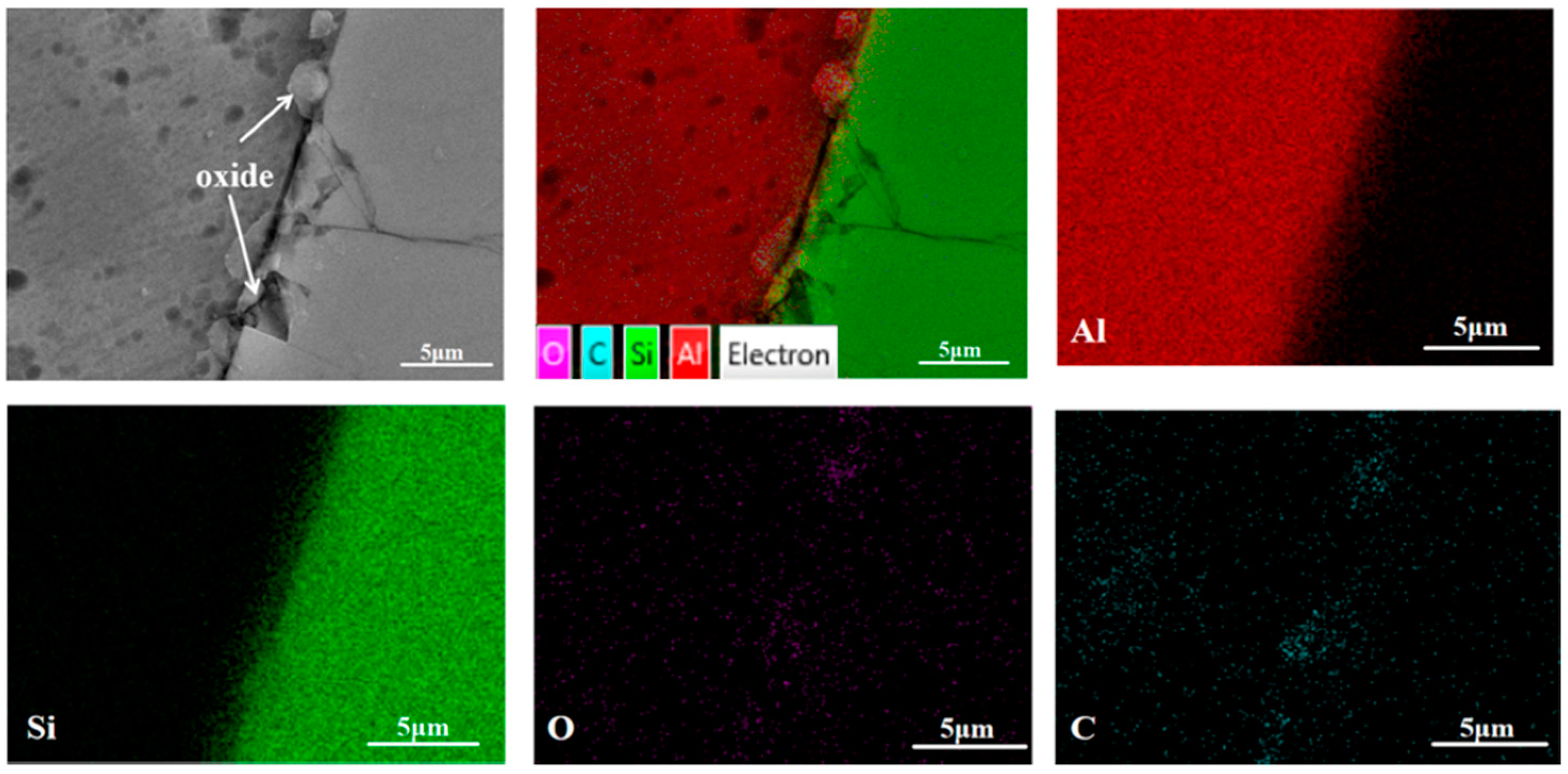
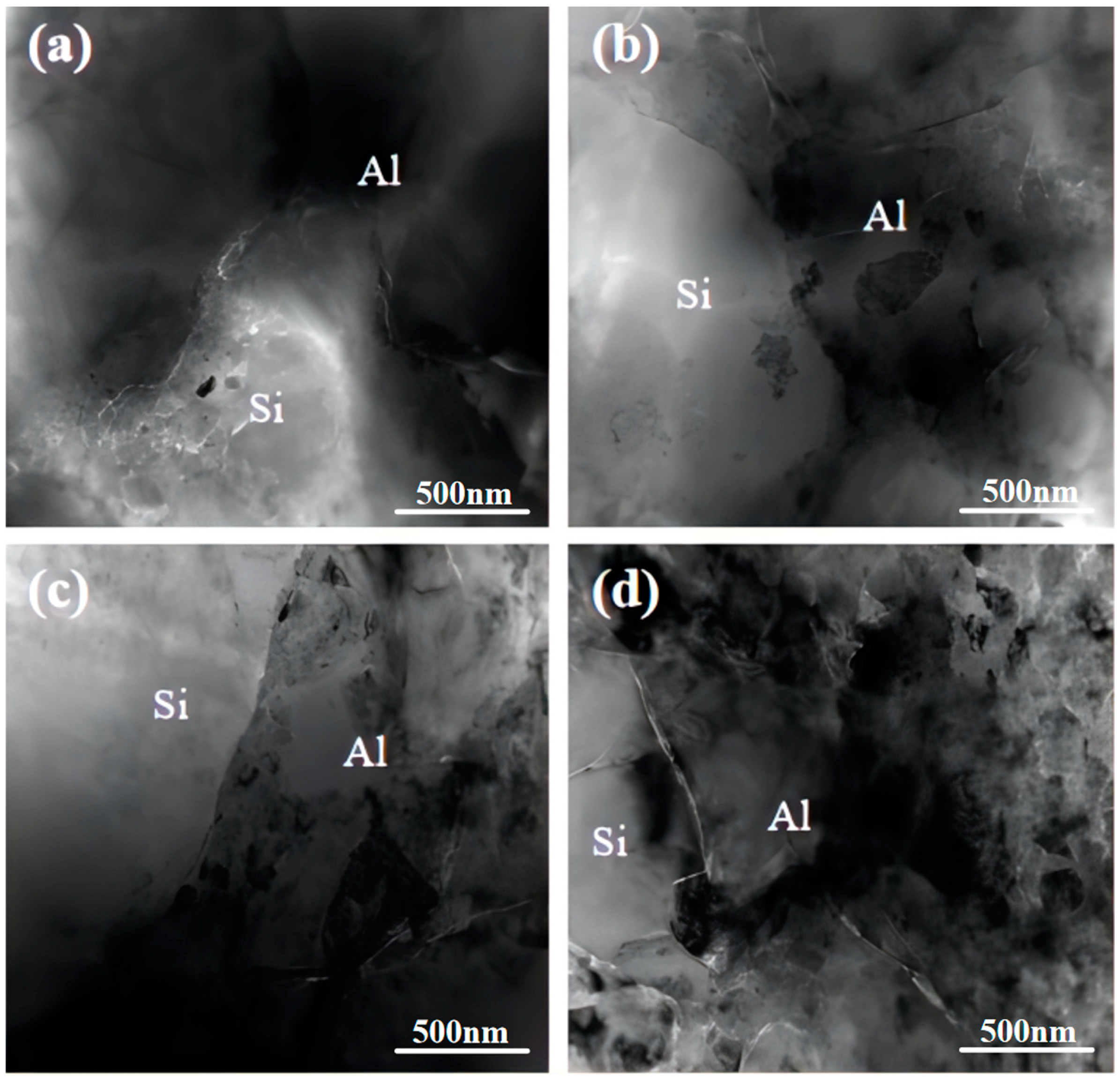
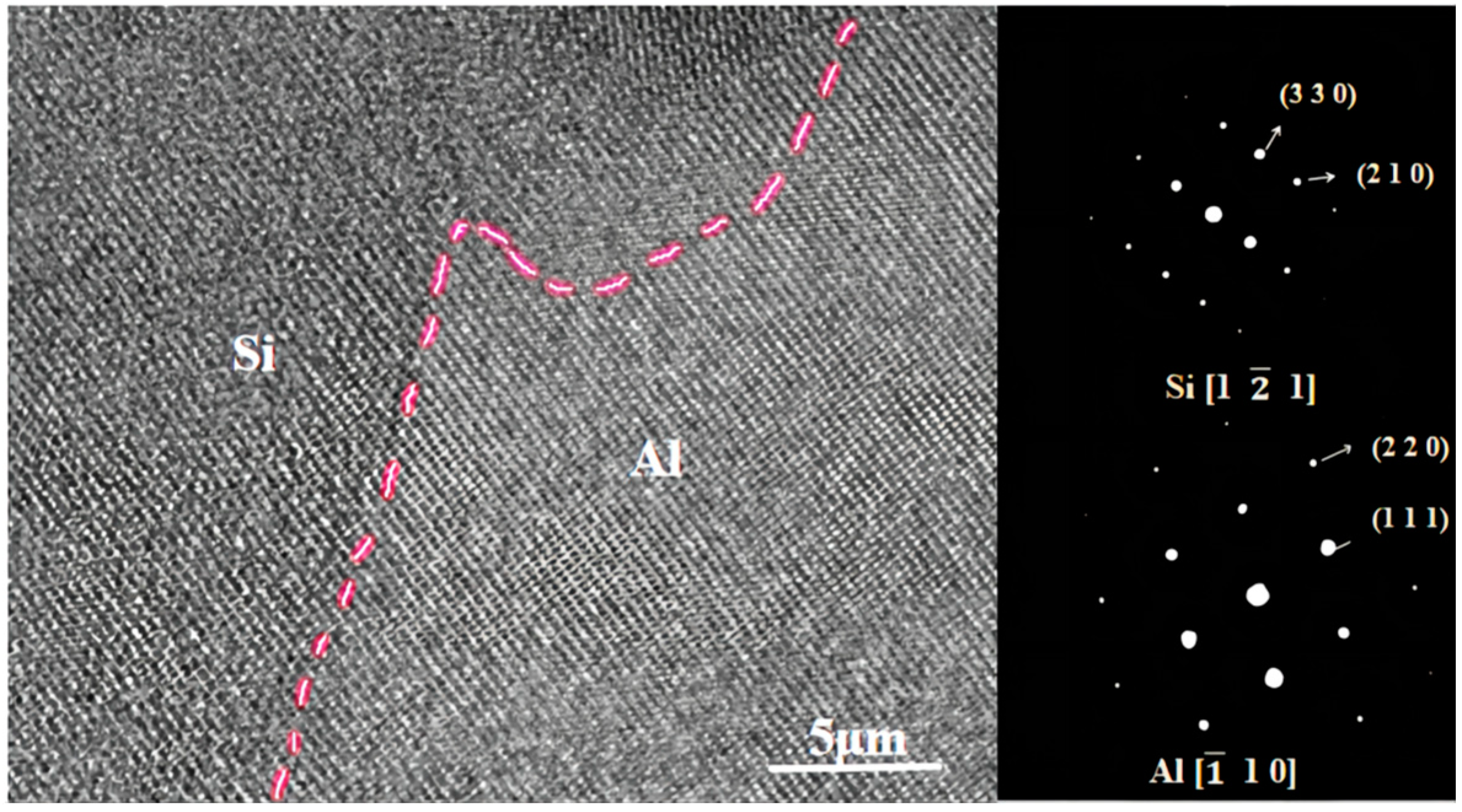
3.1. Influence of Sintering Temperature on the Material Structure and Interface

The choice of sintering temperature plays a crucial role in the fabrication of composite materials through discharge plasma sintering. Figure 3 and Figure 4 show the microstructure and SEM image of the materials at various sintering temperatures. The figures reveal that at lower sintering temperatures, silicon particles were uniformly dispersed within the aluminum matrix. However, there were numerous voids in the composite material, primarily at the two-phase contact points between the aluminum and silicon phases. This indicates that the bonding between the silicon particles and the aluminum matrix was not strong enough. At a sintering temperature of 565 °C, the composite material exhibited a uniform and dense microstructure with no voids, achieving material densification and sintering. The silicon was uniformly distributed within the aluminum matrix without local aggregation. As the sintering temperature continued to increase, the number of voids did not decrease, but increased, and the silicon phase tended to aggregate and grow, which adversely affected the material’s properties.
Figure 5 shows the distribution of the average silicon phase sizes within the composite material at various sintering times. As observed in the figure, the average silicon phase size initially increased and then decreased with increasing sintering temperature. When the sintering temperature reached 565 °C, the composite material exhibited the smallest average silicon phase size. This pattern aligns with the changes depicted in the scanning electron microscope diagram presented in Figure 2. This phenomenon is attributed to the sintering process. At lower temperatures, the current passing through the material was insufficient to generate adequate Joule heat for melting the aluminum particles. Consequently, the material exhibited poor fluidity and struggled to fill the gaps between silicon particles, resulting in the formation of voids and the subsequent agglomeration of silicon phases. Once the temperature reached the densification threshold, the generated Joule heat effectively melted the aluminum, allowing the aluminum particles to fuse and form a connected matrix. This matrix filled the gaps between silicon particles, facilitating the densification process and the creation of a structured matrix connecting the silicon particles. However, as the sintering temperature continued to increase, some of the molten aluminum started to seep, preventing effective filling and leading to the formation of numerous voids. This, in turn, caused the aggregation of silicon phases, and an elevated sintering temperature promoted the growth of silicon phases.
Figure 6 shows the XRD patterns of the composites sintered at different temperatures. The figure reveals that as the temperature increased, along with the characteristic peaks of aluminum and silicon, peaks also emerged corresponding to alumina and silicon oxide in the diffraction pattern. These additional peaks are attributed to the introduction of oxygen during the powder milling process.
Figure 7 shows that as the sintering temperature increased, the most prominent aluminum peak gradually shifted to the right. This shift primarily occurred due to the solid solution of silicon atoms in the aluminum lattice, leading to a reduction in the lattice constant. This phenomenon indicates that higher temperatures facilitated the diffusion of silicon atoms into the aluminum matrix. Consequently, a dissolved wetting interface was formed, characterized by strong bonding, which effectively hindered matrix expansion and reduced the coefficient of thermal expansion.
From the scanning electron microscopy and XRD patterns, we can see that there was a distribution of oxidation particles in the structure of the material, and the oxidation particles were composed of Al2O3 and SiO2. We further observed and analyzed the distribution of the oxide phase. As shown in Figure 8, for the distribution of oxidized particles in the tissue, the amount of Al2O3 in the oxide was greater than that in the SiO2 because the oxidation activity of the Al phase in oxygen was greater than that of the Si phase. The oxide was evenly distributed in the structure of the material, and the small dispersed oxide phase could fill the holes in the material and strengthen the dispersion. Moreover, Al2O3 and SiO2 were heated, which is equivalent to the third rigid term not expanding, and could have played a role in reducing the expansion coefficient of the material. However, when these hard oxide particles were distributed at the interface of the two Al–Si phases, cracks at the bonding interface easily formed during the sintering extrusion process, as shown in Figure 9. Therefore, the presence of oxides could have played a role in reducing the coefficient of thermal expansion of the material, but because of its cutting effect on the interface, this will have also led to the destruction of the organization of the material, and reduced the thermal conductivity of the material.
Figure 10 shows transmission electron microscopy images of the Al–Si interface within the composite material at various sintering temperatures. From the figure, it becomes evident that at both very low and very high sintering temperatures, the Al–Si interface lacked adequate cohesion. However, at moderate sintering temperatures, the Si–Al interface appeared rounded and smooth, indicating that there was a strong bond between them. This results in effective Si diffusion into the aluminum matrix, leading to the formation of a seamless interface and the complete integration of Si with Al.
Figure 11 shows a high-resolution transmission diagram of the composite material interface when it was sintered at 565 °C. The diagram reveals that the Al–Si interface was round and smooth, and devoid of any reactants or noticeable precipitates in the aluminum alloy. This smooth and well-combined Al–Si interface is primarily attributed to the complete diffusion of Si into the aluminum at the optimal sintering temperature, resulting in a dissolved wetting interface with robust bonding strength. This, in turn, significantly reduced the interfacial thermal resistance and enhanced the thermal conductivity of the material.

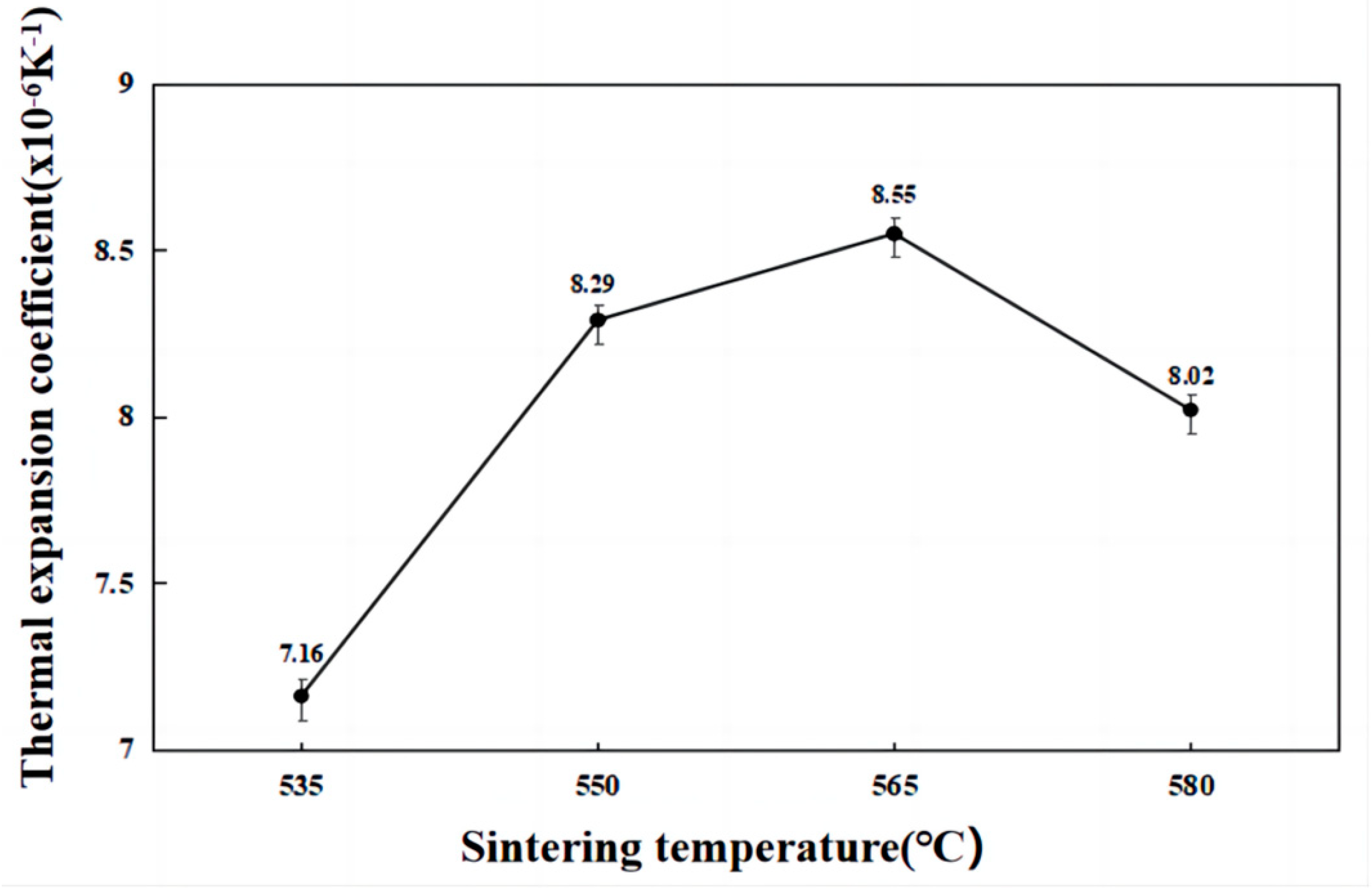
3.2. Influence of Sintering Temperature on Material Properties

Figure 12 shows the effects of different sintering temperatures on the coefficient of thermal expansion of the material. It is evident that as the sintering temperature increased, the thermal expansion coefficient of the material initially increased and then began to decrease with increasing temperature. This phenomenon can be attributed to several factors. First, at lower sintering temperatures, the ability of liquid aluminum to wet silicon particles is suboptimal. Consequently, the aluminum matrix failed to form a complete connected network, and its expansion became more restricted by nearby silicon particles, resulting in a smaller coefficient of thermal expansion. Simultaneously, the silicon particles retained within the aluminum matrix at lower temperatures inhibited matrix expansion. Additionally, under the same sintering pressure conditions, additional pores remained within the material following low-temperature sintering. These pores did not expand when heated and can be considered a rigid third phase with zero expansion. Conversely, at higher sintering temperatures, the molten aluminum was prone to seepage under the influence of pressure. This led to the incomplete formation of a connected aluminum matrix and the creation of additional voids within the structure, ultimately reducing the coefficient of thermal expansion of the material. Therefore, the presence of these pores diminished the coefficient of thermal expansion of the material.
Figure 13 illustrates the variation in thermal conductivity with different sintering temperatures. The thermal conductivity of the material initially increased and then decreased as the sintering temperature changed. The highest thermal conductivity was achieved at a sintering temperature of 565 °C. At lower sintering temperatures, the wettability of the aluminum phase was poorer than that of the silicon phase. This resulted in limited pore-filling effectiveness and inadequate particle rearrangement, leading to the presence of numerous pores within the material. The existence of these pores significantly reduced the thermal conductivity of the material. Additionally, even though the high thermal conductivity of the aluminum matrix resulted in the formation of a continuous network structure, the internal pores in the composite material had a substantial adverse impact on the thermal conductivity. At a sintering temperature of 565 °C, during the liquid-phase sintering process, two-phase wetting was effective, allowing the aluminum matrix to fill the gaps between silicon particles effectively. This, in turn, minimized the presence of holes and other defects within the material, resulting in a dense structure with a low impact of pores on thermal conductivity. At this stage, the high-thermal-conductivity aluminum matrix formed a continuous network structure, significantly enhancing the thermal conductivity of the material. As the sintering temperature continued to increase, the wettability of the two phases during the sintering process further improved. However, in this experimental material, which contained a second phase with a high volume fraction, prolonged sintering led to the formation of localized areas with high concentrations of silicon particles. In these areas, there may have been a limited distribution of aluminum, hindering the flow of molten aluminum. This resulted in the formation of numerous larger pores within the material. Moreover, the continuous aluminum matrix network structure could not compensate for the adverse effects of these pores on the thermal conductivity of the material. Therefore, excessively high sintering temperatures resulted in reduced material thermal conductivity.
Figure 14 illustrates the influence of different sintering temperatures on the material density and relative density. The data reveal that both the material density and relative density initially increased and then decreased as the sintering time increased. The maximum values for both parameters were achieved at a sintering time of 2 h, measuring 2.415 g/cm3 and 97.75%, respectively. At temperatures lower than 565 °C, the density of the sintered sample was highly sensitive to temperature changes. Even slight increases in sintering temperature resulted in an increase in sample density. However, at temperatures higher than 565 °C, the sample density’s sensitivity to temperature decreased significantly. This is due to the material’s properties; if the selected hot pressing temperature was too low, the softening of the mixed powder was insufficient, increasing the deformation resistance and impeding the flow of the metal liquid within the powder. Consequently, the internal voids were not filled well, leading to a decreased density. Conversely, if the selected temperature is too high, the material becomes too soft, allowing the metal liquid to fill voids more effectively, resulting in better densification. However, in a high-temperature environment with pressure, molten metal can seep out, resulting in a poor interfacial connection between the composite material and the reinforcing phase.
Figure 15 depicts the effects of different sintering temperatures on the material hardness. It is evident that the hardness of the composite material initially increased and then decreased as the sintering temperature varied. The maximum Brinell hardness value of 219 HBW was achieved at a sintering temperature of 565 °C. Several factors contributed to the increase in the Brinell hardness with increasing sintering temperature. First, as the sintering temperature increased, interatomic diffusion became more effective, strengthening the interfacial bonding between the matrix and the second phase. Additionally, the presence of defects, such as dislocations in the matrix due to thermal expansion mismatch, may have increased with increasing sintering temperatures, further enhancing the material hardness. When sintering at 565 °C, the material structure was the densest, with few to no voids. Therefore, at this temperature, the Brinell hardness of the material was the highest. However, as the sintering temperature continued to increase, the Brinell hardness of the material significantly decreased. This was primarily due to Si phase agglomeration during prolonged sintering, which obstructed the circulation channel of aluminum, preventing it from filling the voids of the material. This, in turn, led to the formation of numerous holes within the sintered material, directly resulting in a sharp decrease in material hardness.

4. Conclusions

This study focused on high-silicon–aluminum composites with a 60% silicon content. The effects of discharge plasma sintering temperature on the microstructure, phase, average silicon phase size, interface, density, hardness, and thermophysical properties of high-Si–Al composites were analyzed. The following conclusions can be drawn:
(1)
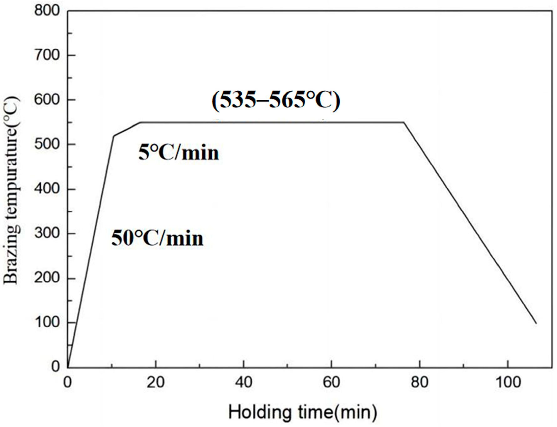
In the discharge plasma sintering process, the sintering temperature is a critical parameter. Within a certain range, increasing the temperature and extending the sintering time can effectively enhance the material’s wettability. This enables full particle rearrangement and dissolution–precipitation processes, ultimately improving the microstructural properties of the materials;
(2)
The material achieves its most compact microstructure and the smallest number of pores at a sintering temperature of 565 °C;
(3)
At a sintering temperature of 565 °C, the material exhibited a thermal expansion coefficient of 8.55 × 10⁶ K−1, a high thermal conductivity of 134.6 W/m·K, a density and relative density of 2.415 g/cm3 and 97.75%, respectively, and a high hardness of 219 HBW. These characteristics represent the best overall performance, meeting the requirements of electronic packaging materials.

Author Contributions

Conceptualization, Z.K. and Z.W.; methodology, Z.K. and Z.W.; software, Z.K.; validation, Z.W. and R.L.; formal analysis, Z.K.; investigation, Z.K.; resources, R.L.; data curation, Y.L. and R.L.; writing—original draft preparation, Z.K.; writing—review and editing, Z.W. and R.L.; supervision, Y.L. and R.L.; project administration, Y.L. and R.L. All authors have read and agreed to the published version of the manuscript.

Funding

The author expresses their gratitude to the National Natural Science Foundation of China (No.51974092); Key-Area Research and Development Program of Guangdong Province (No.2020B010186002); Guangdong Provincial Key Laboratory of Advanced Forming of Light Metal Materials (No.2021B1212050001); Guangdong Basic and Applied Basic Research Foundation (No.2020A1515110386).

Institutional Review Board Statement

Not applicable.

Informed Consent Statement

Not applicable.

Data Availability Statement

The data used to support the findings of this study are available from the corresponding author upon request.

Conflicts of Interest

The authors declare no conflict of interest.

References

  1. Feng, C.P.; Yang, L.Y.; Yang, J.; Bai, L.; Bao, R.Y.; Liu, Z.Y.; Yang, W. Recent advances in polymer-based thermal interface materials for thermal management: A mini-review. Compos. Commun. 2020, 22, 100528. [Google Scholar] [CrossRef]
  2. Burger, N.; Laachachi, A.; Ferriol, M.; Lutz, M.; Toniazzo, V.; Ruch, D. Review of thermal conductivity in composites: Mechanisms, parameters and theory. Prog. Polym. Sci. 2016, 61, 1–28. [Google Scholar] [CrossRef]
  3. Li, R.; Yang, X.; Li, J.; Shen, Y.; Zhang, L.; Lu, R.; Zhang, T. Review on polymer composites with high thermal conductivity and low dielectric properties for electronic packaging. Mater. Today Phys. 2022, 22, 100594. [Google Scholar] [CrossRef]
  4. Yu, K.; Li, S.J.; Chen, L.S. Microstructure characterization and thermal properties of hypereutectic Si-Al alloy for electronic packaging applications. Trans. Nonferrous Met. Soc. China 2012, 6, 1412–1417. [Google Scholar] [CrossRef]
  5. Wang, F.; Xiong, B.; Zhang, Y.; Zhu, B.; Liu, H.; Wei, Y. Microstructure, thermo-physical and mechanical properties of spray-deposited Si–30Al alloy for electronic packaging application. Mater. Charact. 2008, 10, 1455–1457. [Google Scholar] [CrossRef]
  6. Jun, F.A.N.G.; Zhong, Y.H.; Xia, M.K.; Zhang, F.W. Mechanical and thermo-physical properties of rapidly solidified Al50SiCu(Mg) alloys for thermal management application. Trans. Nonferrous Met. Soc. China 2021, 31, 586–594. [Google Scholar]
  7. Zhang, W.; Ding, D.; Gao, P. High volume fraction Si particle-reinforced aluminium matrix composites fabricated by a filtration squeeze casting route. Mater. Des. 2016, 90, 834–838. [Google Scholar] [CrossRef]
  8. Raghukiran, N.; Kumar, R. Effect of scandium addition on the microstructure, mechanical and wear properties of the spray formed hypereutectic aluminum–silicon alloys. Mater. Sci. Eng. A 2015, 641, 138–147. [Google Scholar] [CrossRef]
  9. Liu, Y.Q.; Wei, S.H.; Fan, J.Z.; Ma, Z.L.; Zuo, T. Mechanical Properties of a Low-thermal-expansion Aluminum/Silicon Composite Produced by Powder Metallurgy. J. Mater. Sci. Technol. 2014, 30, 417–422. [Google Scholar] [CrossRef]
  10. Jia, Q.J.; Liu, J.Y.; Li, Y.X.; Wang, W.S. Microstructure and properties of electronic packaging box with high silicon aluminum-base alloy by semi-solid thixoforming. Trans. Nonferrous Met. Soc. China 2013, 23, 80–85. [Google Scholar] [CrossRef]
  11. Caiju, L.; Jidong, Z.; Xinkun, Z.; Bingbing, S.; Hailin, T.; Jie, L.; Mengchun, X. Preparation of pure Aluminum nanocrystalline materials by High energy ball milling. Powder Metall. 2006, 24, 457–459. [Google Scholar]
  12. Saraswat, E.; Maharana, H.S.; Murty, S.N.; Shekhar, S.; Kar, K.K.; Ramkumar, J.; Mondal, K. Fabrication of Al-Si controlled expansion alloys by unique combination of pressureless sintering and hot forging. Adv. Powder Technol. Int. J. Soc. Powder Technol. Jpn. 2020, 31, 2820–2832. [Google Scholar] [CrossRef]
  13. Almubarak, A.A. The Effects of Heat on Electronic Components. Int. J. Eng. Res. Appl. 2017, 7, 52–57. [Google Scholar] [CrossRef]
  14. Lee, H.S.; Jeon, K.Y.; Kim, H.Y.; Hong, S.H. Fabrication process and thermal properties of SiCp/Al metal matrix composites for electronic packaging applications. J. Mater. Sci. 2000, 35, 6231–6236. [Google Scholar] [CrossRef]
  15. Wan, Y.J.; Li, G.; Yao, Y.M.; Zeng, X.L.; Zhu, P.L.; Sun, R. Recent advances in polymer-based electronic packaging materials. Compos. Commun. 2020, 19, 154–167. [Google Scholar] [CrossRef]
  16. Dai, H.A.; Liu, X.F. Refinement performance and mechanism of an Al-50Si alloy. Mater. Charact. 2008, 59, 1559–1563. [Google Scholar] [CrossRef]
  17. Liu, Z.; Liang, J.; Su, S.; Zhang, C.; Li, J.; Yang, M.; Wang, D. Preparation of defect-free alumina insulation film using layer-by-layer electrohydrodynamic jet deposition for high temperature applications. Ceram. Int. 2021, 47, 14498–14505. [Google Scholar] [CrossRef]
  18. Li, Y.X.; Liu, J.Y.; Wang, W.S.; Liu, G.Q. Microstructures and properties of Al-45%Si alloy prepared by liquid-solid separation process and spray deposition. Trans. Nonferrous Met. Soc. China 2013, 23, 970–976. [Google Scholar] [CrossRef]
  19. Alves, S.J.F.; de Sousa, M.M.S.; de Araújo, E.R.; Filho, F.A.; dos Santos, M.J.; de Araújo Filho, O.O. Processing of Metal Matrix AA2124 Aluminium Alloy Composites Reinforced by Alumina and Silicon Carbide by Powder Metallurgy Techniques. Mater. Sci. Forum 2014, 802, 84–89. [Google Scholar] [CrossRef]
  20. Wei, L.; Zhenhua, C.; Ding, C.; Cang, F.; Canrang, W. Thermal fatigue behavior of Al–Si/SiCp composite synthesized by spray deposition. J. Alloys Compd. 2010, 504 (Suppl. S1), S522–S526. [Google Scholar] [CrossRef]
  21. Qiu, T.; Wu, M.; Du, Z.; Chen, G.; Zhang, L.; Qu, X. Microstructure evolution and densification behaviour of powder metallurgy Al-Cu-Mg-Si alloy. Powder Metall. 2020, 63, 54–63. [Google Scholar] [CrossRef]
  22. Etter, T.; Papakyriacou, M.; Schulz, P.; Uggowitzer, P.J. Physical properties of graphite/aluminium composites produced by gas pressure infiltration method. Carbon 2003, 41, 1017–1024. [Google Scholar] [CrossRef]
  23. Yu, K.; Li, C.; Wang, R.; Yang, J. Production and Properties of a Spray Formed 70%Si-Al. Mater. Trans. 2008, 49, 685–687. [Google Scholar] [CrossRef]
  24. Lee, J.I.; Hong, T.W.; Kim, I.H.; Ur, S.C.; Lee, Y.G.; Ryu, S.L. Synthesis and Evaluations of Microstructure Properties on Al-(50, 60, 70 mass%)Si Systems by Mechanical Alloying. Mater. Sci. Forum 2004, 449, 249–252. [Google Scholar] [CrossRef]
  25. Fan, X.; Ni, N.; Wang, X.; Hao, W.; Guo, F.; Zhao, X. Mechanically isotropic alumina prepared by spark plasma sintering: The role of pyrolytic carbon and multilayer graphene. J. Eur. Ceram. Soc. 2021, 41, 4242–4251. [Google Scholar] [CrossRef]
  26. Rousselle, M.; Ansart, F.; de Beauvoir, T.H.; Fradet, G.; Estournès, C. Phase evolution and sinterability of lanthanum phosphate-towards a below 600 °C Spark Plasma Sintering. J. Eur. Ceram. Soc. 2021, 41, 7261–7268. [Google Scholar] [CrossRef]
  27. Lee, J.H.; Oh, I.H.; Jang, J.H.; Kim, J.H.; Hong, S.K.; Park, H.K. Effect of Mechanical Alloying on the Microstructural Evolution of Al60Cr30Si10 Alloys Processed by Spark Plasma Sintering. Met. Mater. Int. 2020, 27, 1147–1154. [Google Scholar] [CrossRef]
  28. Vidyasagar, C.S.; Karunakar, D.B. Effect of spark plasma sintering and reinforcements on the formation of ultra-fine and nanograins in AA2024-TiB2-Y hybrid composites. Prog. Nat. Sci. Mater. Int. 2022, 32, 79–86. [Google Scholar] [CrossRef]
  29. Zhang, X.; Qin, Y.; Jin, J. High-efficiency and energy-conservation grinding technology using a special ceramic-medium stirred mill: A pilot-scale study. Powder Technol. 2022, 396, 354–365. [Google Scholar] [CrossRef]
Figure 1. Heating curve of the brazing process.
Coatings 14 00299 g001
Figure 2. Graphite mold, sintering process and macroscopic sample. (a) Graphite mold, (b) sintering process, (c) whole sample picture.
Coatings 14 00299 g002
Figure 3. Microstructure of the Al–Si composites sintered at different temperatures. (a,b) 535 °C, (c,d) 550 °C, (e,f) 565 °C, (g,h) 580 °C.
Coatings 14 00299 g003
Figure 4. SEM images of the Al–Si composites sintered at different temperatures. (a) 535 °C, (b) 550 °C, (c) 565 °C, (d) 580 °C.
Coatings 14 00299 g004
Figure 5. Average silicon phase size.
Coatings 14 00299 g005
Figure 6. XRD patterns at different sintering temperatures.
Coatings 14 00299 g006
Figure 7. Displacement of the Al (111) reflection peak with sintering temperature.
Coatings 14 00299 g007
Figure 8. The distribution of the oxide phase.
Coatings 14 00299 g008
Figure 9. The distribution of oxides at the interface.
Coatings 14 00299 g009
Figure 10. TEM images of the Al–Si composites at different sintering temperatures. (a) 535 °C, (b) 550 °C, (c) 565 °C, (d) 580 °C.
Coatings 14 00299 g010
Figure 11. HRTEM diagram and FFT diagram at a sintering temperature of 565 °C.
Coatings 14 00299 g011
Figure 12. Effect of the sintering temperature on the thermal expansion coefficient of the Al–Si composite.
Coatings 14 00299 g012
Figure 13. Effect of the sintering temperature on the thermal conductivity of the Al–Si composite.
Coatings 14 00299 g013
Figure 14. Effect of the sintering temperature on the density and relative density.
Coatings 14 00299 g014
Figure 15. Effect of the sintering temperature on the hardness.
Coatings 14 00299 g015
Table 1. Main raw materials used in the experiments.
ElementPurity (wt. %)Median Particle Size (µm)
Al≥99.525
Si≥99.510
Disclaimer/Publisher’s Note: The statements, opinions and data contained in all publications are solely those of the individual author(s) and contributor(s) and not of MDPI and/or the editor(s). MDPI and/or the editor(s) disclaim responsibility for any injury to people or property resulting from any ideas, methods, instructions or products referred to in the content.

