Article

A One-Step Novel Method to Fabricate Multigrade Ti6Al4V/TiN Composites Using Laser Powder Bed Fusion

Department of Material Science and Metallurgical Engineering, Rey Juan Carlos University, 28933 Madrid, Spain
*
Author to whom correspondence should be addressed.
Coatings 2024, 14(1), 90; https://doi.org/10.3390/coatings14010090
Submission received: 31 October 2023 / Revised: 4 January 2024 / Accepted: 5 January 2024 / Published: 9 January 2024
(This article belongs to the Special Issue Additive Manufacturing of Metallic Components for Hard Coatings)

Abstract

:
Ti6Al4V is the most used alloy for implants because of its excellent biocompatibility; however, its low wear resistance limits its use in the biomedical industry. The additive manufacturing (AM) of Ti6Al4V is a well-established technique that is being used in many fields. However, the AM of Ti6Al4V composites is currently under investigation, and its manufacture using laser powder bed fusion (L-PBF) would result in a great benefit for many industries. The one-step novel concept proposed uses a gas-controlled L-PBF system that enables the AM of layers with different compositions. Six millimeter-edged cubes of Ti6Al4V were manufactured in an Ar atmosphere and coated with in situ Ti6Al4V/TiN layers by using an Ar–N2 mixture given the direct reaction between titanium and nitrogen. Unreinforced Ti6Al4V presented a martensitic microstructure, and TiN reinforcement dendrites and a minor Ti2N phase were gradually introduced into an α + β basketweave titanium matrix. The composites’ microhardness, nanohardness, and elastic modulus were 2, 3, and 1.5 times higher, respectively, than those of the Ti6Al4V. Porosity levels (caused by a lack of fusion, trapping gases, and interdendritic porosity), ranged from 7 to 12% (most measured 20–40 µm) and increased with the reinforcement content (15 to 25%). A scaled-up, proof-of-concept design of a hip implant stem was 3D printed using this nitriding method. Since the neck of the stem (top part) is more susceptible to the fracture and fretting corrosion process, the resulting graded material part consisted of unreinforced Ti6Al4V at the bottom and Ti6Al4V/TiN at the top. This change was controlled by gradually adding nitrogen to the atmosphere; moreover, it was found that the more nitrogen in the chamber, the more TiN reinforcement formed in the part. A microhardness of ~450 HV0.1 was measured at the bottom and gradually increased to ~900 HV0.1, with the increment corresponding to the in situ TiN reinforcement amount.

1. Introduction

Ti6Al4V is an α-β-type titanium alloy that has been widely applied for joint implants in biomedicine due to its great biocompatibility and osseointegration, high corrosion resistance, and lightweight [1,2]. Nevertheless, Ti6Al4V prostheses have the disadvantage of presenting low wear resistance that causes toxicity and even implant failure [2,3]. Ceramic coatings such as TiN provide good chemical stability and high stiffness and can be deposited on titanium alloys to enhance the tribological properties of the material. TiN coatings exhibited a decrease in the friction coefficient and, therefore, better wear behavior [4,5,6].
Titanium matrix composites (TMCs) reinforced with titanium nitride combine the excellent properties of titanium alloys with the hardness and stiffness of TiN while avoiding the brittleness of TiN ceramics. Therefore, the load transfer between matrix and reinforcement improves mechanical (microhardness) and tribological (wear behavior) properties due to the formation of dendritic microstructures in the metal matrix [7,8]. However, the high melting temperature of titanium and its alloys, together with their high reactivity, especially with oxygen, makes it very difficult to manufacture these composites using liquid routes [9]. The development of new processing routes for them is very attractive to the industry [10,11].
Additive manufacturing (AM) is a fabrication method for producing 3D parts by depositing material layer by layer from a computer-aided-design (CAD) [12]. This technology provides high manufacturing flexibility, which is advantageous for the manufacturing of implants that need to be customized for each patient. In addition, AM allows for a significant waste reduction, the use of a wide range of materials, the ability to produce parts with high strength-to-weight ratios, and complex structures for topology optimization. Topology optimization was designed as an advanced structural method that enables a high-performance and lightweight optimal structure configuration [13]. Increasing the part strength along with the weight reduction is the best strategy to reduce fuel consumption and obtain more sustainable solutions for aerospace [14]. Nevertheless, it is complex to fabricate TMCs, and further research is needed. Laser powder bed fusion (L-PBF) is one of the most widely used AM techniques since it combines the possibility to produce high-value items with economic and technical advantages [15]. In L-PBF, a thin layer of metallic powder is deposited, and a laser is used to melt selected areas of the powder deposited. The accumulation of layers, each one molten in the preselected zones, gives rise to the formation of tridimensional samples with almost any morphology guided by a CAD model. The process is generally performed in an inert atmosphere, preferentially Ar, to prevent changes in the composition of the material used during manufacturing [16,17]. Different types of lasers can be used in LPBF, including fiber lasers, the most common energy sources in AM, and CO2 lasers, which, despite their lower stability, have been used in L-PBF at lower costs, with output power from 0.1 to 20 kW and at high efficiency (20%) [18]. In CO2 lasers, a gas is electrically pumped by a current to induce the population inversion required for the laser emission. The main disadvantage is that this type of laser emits at a wavelength of 10.6 µm, which results in difficult control and large divergences [19]. They also have low absorption to many metals [20]. However, they are available in a wide range of powers, beam qualities, and laser modes; therefore, it is necessary to explore the limits of this technology to apply it in LPBF and to investigate the possibility of implanting low-cost 3D printers for metals. In the case of the Ti6Al4V alloy, this LPBF system, equipped with a CO2 laser, has been able to produce parts with good corrosion and mechanical results [21].
The modification of the atmosphere by introducing a reactive gas into the L-PBF chamber allows the manufacture of materials with a composition that is different from that of the metallic powder used [22]. In particular, nitrogen in the atmosphere reacts with the molten titanium to form TiN [1,10,11,23]. If this reaction is not complete, i.e., not all the metal is irradiated with the laser, it is possible to, in situ, obtain small TiN particles that act as a ceramic reinforcement in a Ti6Al4V alloy matrix [24]. The resulting composite shows improved mechanical and tribological properties compared with the unreinforced alloy [10,25,26]. P. Rodrigo et al. (2015) [27] showed that in situ Ti-TiN composite coatings can be fabricated using laser cladding and patented it. Other researchers have fabricated Ti6Al4V coatings with in situ TiN using this and other AM technologies. W. Wei et al. (2021) [23] synthesized in situ TiN-reinforced Ti6Al4V matrix composites by using the gas–liquid reaction in nitrogen-reactive atmospheres with L-PBF techniques, and properties such as microhardness and compressive yield strength increased with the nitrogen concentration. S. Mridha et al. [28] studied the laser nitriding of commercially pure titanium in dilute and undilute nitrogen atmospheres and concluded that the surface hardness increased with the nitrogen concentration and that the surface cracking could be controlled either by controlling the manufacturing parameters in pure nitrogen or by nitriding in a dilute nitrogen environment. T. W. Na et al. (2018) [29] analyzed the variation of mechanical properties of pure titanium by modifying the laser power in selective laser melting in an argon atmosphere. They increased the oxygen and nitrogen concentrations during the manufacturing, and the oxidation and nitriding of pure Ti increased its hardness and strength. However, there have been no studies on the effect of manufacturing the samples with changes in the composition of the atmosphere during the manufacture of the samples.
The Ti6Al4V alloy is commonly used for hip implants [30]. This α + β metallic alloy is suitable for the manufacture of prostheses due to its good mechanical properties, low density, lifecycle and replacement cost benefits, and superior biocompatibility and corrosion resistance. However, its wear and fatigue resistance are not sufficient for the stress cycles to which they are subjected. Most hip implants fail due to a complication of debris generation and wear deterioration in a humid environment when two materials with different mechanical properties are in contact, leading to a tribocorrosion process that includes fretting corrosion. Therefore, research has focused on the development of materials that minimize the generation of debris [31]. J. Geringer et al. studied the regions of the hip stem where the fretting corrosion occurs and generates metallic oxide debris; in particular, this is the top part of the stem, between the femoral stem and the bone cement [32]. Ceramic TiN reinforcements improve the bioactivity and the mechanical properties of the titanium alloy and reduce the toxicity degree. TiN-reinforced titanium matrix composites are mainly used due to their high corrosion and wear resistance, high tensile strength, and fatigue and creep resistance [33].
In the present research, a novel methodology has been developed to fabricate in one step a multigrade titanium matrix composite reinforced with in situ TiN by incorporating nitrogen during the L-PBF process. The L-PBF system used was equipped with a CO2 laser that allowed the melting of the titanium alloy powder that reacted with the nitrogen in the atmosphere to form the reinforcement in situ. The resulting composite showed a strong improvement in mechanical properties compared to Ti6Al4V due to the good quality of the matrix–reinforcement interface. The same procedure was used to fabricate a scaled-up proof-of-concept hip implant in one step with gradual compositions in different zones to meet the requirements of each one. The lower part of the stem (~75% of the part) was made of unreinforced Ti6Al4V in an Ar inert atmosphere, and the upper part, i.e., the neck of the stem, which is susceptible to suffer fretting corrosion [32], was made of Ti6Al4V/TiN in a reactive atmosphere using the gradual addition of nitrogen up to a 50:50 Ar–N2 mixture, resulting in an in situ nitriding reaction that gradually formed the TiN reinforcement for the composite in situ. The proof-of-concept design shows that it is possible to manufacture an implant composed of a Ti6Al4V base material with Ti6Al4V/TiN composite material in the most critical area. All of it can be printed in a single step with morphology and dimensions personalized for each patient. Therefore, it has been demonstrated that this nitriding process can be used with L-PBF to manufacture biomedical parts in one step with properties that outperform those of the titanium alloys used.

2. Materials and Methods

Commercial powder of Ti6Al4V was supplied by Renishaw and had a spherical morphology with a particle size of D50 = 20.33 μm and density of ρ = 4.42 g cm−3. The composition was Al 5.50%–6.50%, V 3.50%–4.50%, and Ti balance. An Aurora Labs (Canning Vale, Australia) S-Titanium Pro L-PBF additive manufacturing printer was used to manufacture 6 mm-edged cubes that were designed with CAD and sliced with Craftware slicing software version 1.20. The equipment consisted of two CO2 lasers with a combined power of 300 W (150 W each) that were focalized in a 0.150 mm diameter spot and were used to melt the Ti6Al4V powder layer by layer. Both the build platform and the powder were preheated to 70 °C. During manufacture, oxygen was kept below 0.5% to avoid the oxidation of the materials. In total, 6 parts were fabricated: 3 by using just argon, and thus they were composed by the Ti6Al4V base material, and 3 by using a mixture of argon and nitrogen in the top of the samples. Initially, the inert gas used was argon, and, for the formation of composite layers, a 50:50 mixture of argon and nitrogen was introduced in the chamber in the middle of the manufacturing process. The processing parameters used were a laser scanning speed of 50 mm/s, hatch distance of 0.1 mm, laser power of 300 W, infill angle of 67° between layers to achieve a more isotropic structure [34], and a layer thickness of 0.06 mm.
Samples were metallographically prepared: cross-sections were cut, mounted in an electrically conductive resin, wet grounded using a sequence of abrasive silicon carbide (400 to 4000 grit size), and polished with a 1 µm diamond solution, using ethylene glycol as a lubricant. Samples were etched in a 5 vol.% HF solution to study their microstructure.
Microstructures were evaluated with a scanning electron microscope (SEM; Hitachi S-3400N), equipped with an energy dispersive X-ray spectrometer (EDS). The setting vacuum was <1 Pa, the acceleration voltage was between 10 and 20 kV, and both SE and BSE modes were used. The reinforcement rate and porosity were determined from the SEM images using Leica image analysis software (LAS version 1.4.5).
X-ray diffraction (XRD) was performed with a Panalytical X’Pert PRO diffractometer (Malvern, UK), the 2θ scanning range was from 10 to 100 degrees with a step of 0.02°, and the acquisition time was 20 s. X’Pert HighScore Plus software (version 4.0) was used to analyze the spectrums and identify the different phases. The radiation source was Cu Kα (λ = 1.5406 Å), operating at 45 kV and 300 mA.
Porosity distribution (% and pore size) was measured by using an optical microscope (Leica DMR, Wetzlar, Germany) equipped with Leica Image ProPlus software (LAS version 1.4.5). At least 10 different images in total were taken from each zone of the printed parts, taking into consideration the three composite material cubes, and measurements were performed with SemAfore software (version 5.2).
Vickers microhardness (980.7 mN applied load, HV0.1, and 15 s) values were measured by using an HMV-2TE Shimadzu (Kyoto, Japan) microhardness tester with a pyramid indenter from a minimum of 10 microindentations from the bottom to the top of the sample with distances of 600 μm from the 3 different cube samples, and of 3 mm from the scaled-up proof of concept. Tests were carried out according to the UNE-EN ISO 6507-1:2006 standard. Nanoindentation tests were carried out to determine the nanohardness and elastic modulus of the different phases. The tests were performed in an MTS Nanoindenter XP device (MTS Systems Corporation, Oak Ridge, TN, USA) using a Berkovich pyramidal diamond tip working in quasi static mode, called XP, with a load of 1gf (10 mN) applied for 10 s. A matrix of 50 indentations, 10 in the fabrication direction (z-axis) and 5 along the width of the sample (x-axis), with a distance of 250 μm between indentations, was carried out to analyze the different zones/microstructures of the materials.
The stem scaled-up proof of concept was designed and sliced using the same software as the fabricated samples and was also manufactured using Ti6Al4V commercial powder and Aurora Labs S-Titanium Pro. In this case, the percentage of nitrogen in the carrying gas introduced in the chamber was gradually increased from 0 to 50 wt.% at the top of the sample (when 75% of the part was completed), while the percentage of argon was gradually decreased from 100 to 50 wt.%, obtaining a 50:50 mixture of argon–nitrogen during the last stage of the manufacturing process.

3. Results and Discussion

3.1. Phase Analysis

The samples manufactured using Ar showed a homogeneous composition and characteristics over the whole cube, and the samples manufactured replacing Ar with a 1:1 Ar:N2 gradually changed in color (from silver to golden), revealing that the material had a different composition (Figure 1a). The final dimensions of the cubes were measured to evaluate the dimensional accuracy of the process and were 6.0 ± 0.1 mm high and 6.0 ± 0.4 mm wide, with the x-axis being the most distorted one.
The XRD analysis performed on the materials (Figure 1b) showed the main presence of the α/α′ martensite phase in the sample fabricated with only an argon atmosphere. In addition, a minor β peak has been detected. However, in the zone fabricated with an Ar:N2 mixture, α and β titanium peaks were identified. Moreover, in the material manufactured in the nitrogen mixture, peaks corresponding to TiN and Ti2N were observed, and the TiN one was much stronger.

3.2. Microstructural Analysis

Figure 2a shows the microstructure of the unreinforced Ti6Al4V material, and Figure 2b is an image taken at higher magnification in the same sample. The Ti6Al4V manufactured in Ar (Figure 2a,b) exhibited a martensitic microstructure. During the L-PBF build-up, a layer was molten and solidified, and the fast cooling caused the formation of an α′ martensite. In this phase, the vanadium, which is a β stabilizer element, could not segregate along the molten pool, causing the apparition of needles of the α phase with high concentrations of vanadium, which was the final α′ phase [35].
The defectology present in the samples is also marked in Figure 2 and Figure 3. Three types of defects are commonly detected in SLM printed parts: spherical pores, caused by the trapping of gases (Figure 2b); interdendritic porosity, formed due to the metal contraction during the solidification process; and lack of fusion, caused by the insufficient melting of the material and the residual stress (Figure 3a).
The microstructure of the layers manufactured in nitrogen (the top part of the sample) is shown in Figure 2c,d. This part of the sample showed the typical TiN dendrites morphology of the reinforcement (Figure 2c) and underneath an α + β titanium matrix (Figure 2d). The interdendritic porosity described above is identified in this image. To show the difference in chemical composition, a BSE detector was used. The TiN dendrites are visible as darker areas because their total atomic number is lower than that of Ti6Al4V. The laser melted the Ti particles and promoted their reaction with N2 in the molten pools to form TiN dendrites (with a size up to 50 µm), while a minor Ti2N phase was formed. An EDS Element map performed in the area exhibited in Figure 2d confirmed that nitrogen was present in these dendrites (Figure 2e).
The transition of the microstructure from the Ti6Al4V alloy to the TiN-Ti6Al4V composite is shown in Figure 3, where the first layers manufactured with nitrogen in the chamber can be observed.
Figure 3a shows the transition zone with nitrogen-rich regions, shown in light grey, which had the characteristic morphology of the TiN dendrites, and coexisted with titanium-rich regions (darker regions in the SEM-SE image), whose martensite microstructure was similar to the layers manufactured with argon. The formation and appearance of these layers at the transition zone arose from the molten pool creation during the manufacturing, in which the increasing nitrogen amount in the chamber allowed the formation of a few layers of composite material. TiN dendrites formed on the Ti6Al4V matrix are shown in more detail in Figure 3b. High temperatures allowed the direct reaction between nitrogen and molten titanium to form the TiN reinforcement dendrites, whose morphology and size depended on the maximum temperatures reached, the cooling rates during solidification, and the nitrogen amount available [36]. The interface between the TiN/Ti and martensitic titanium layers is shown in Figure 3c. Three distinct zones were identified in this interface. Zone 1 corresponded to the Ti martensite matrix; zone 2 was formed in areas close to the TiN dendrites, where the Ti exhibited a larger plate with an α + β microstructure; zone 3 corresponded to the TiN dendrites that coexist with the α+β basketweave Ti metal matrix.
In zones 2 and 3, the α + β microstructure was formed due to the martensite critical cooling rate. These were related to the lower melt pool temperature in the nitrogen atmosphere (higher ionization energy and lower thermal conductivity). In addition, the α + β basketweave microstructure was formed because new colonies nucleated and grew perpendicularly to the present lamellas [37,38]. The grain size of the laminar structure of the Ti matrix in zone 3 was smaller than in zone 2 due to the higher nucleation due to the presence of TiN.
The porosity of the unreinforced Ti6Al4V (lower region of the sample) was 5.0 ± 0.3%. In the transition zone of the multigrade sample, the average TiN reinforcement percentage values were 15.0 ± 2.8%, and porosity was 7.0 ± 0.5%. In the subsequent layers made with a mixture of Ar:N2, the porosity was 10.0 ± 1.2% and the reinforcement was 23.0 ± 3.1%. In the top of the sample, after the stabilization of the composite manufacture, the porosity was 12.0 ± 1.5%, with 25.0 ± 4.2% reinforcement. Porosity was greater in the zones manufactured with nitrogen. The increase in porosity in the TiN area was due to the lower wettability between the titanium matrix and the TiN reinforcement, which increased the molten pools’ viscosity due to the presence of a solid phase. Thus, this high viscosity created pores via contraction during the solidification stage (shrinkage cavities), as well as due to interdendritic porosity [36]. A histogram with the porosity distribution for the TiN-reinforced material is plotted in Figure 4. The voids ranged in size from 5 to 300 µm, and most pores had sizes between 20 and 40 µm.

3.3. Mechanical Properties Analysis

The measured microhardness and reinforcement percentage are shown in Figure 5a. The microhardness of the AM Ti6Al4V sample (red squares) was homogeneous with a value of 430 ± 30 HV0.1. The same values were obtained in the layered material (black squares) before the application of nitrogen. With the incorporation of nitrogen, the microhardness in the transition layers gradually increased to a maximum of 950 ± 50 HV0.1, i.e., 120% higher. An increase in microhardness was also observed in the first layers produced in nitrogen. The reinforcement rate evolution, i.e., the proportion of TiN, is also represented in Figure 5a (blue triangles). The reinforcement % increased from 0 (where only Ar was used) to values of 15.0 ± 2.8% in the transition zone, where the nitrogen was first introduced in the printing chamber, up to maximum values of 25.0 ± 4.2% at the top of the sample, where the 50:50 Ar–N2 mixture was well established. These are average values; however, there are parts of the composite sample (where the molten pools were created) where the reinforcement % increased up to 50% since more nitrogen that favors the direct reaction with the molten titanium was present. The measurements confirmed that there was a direct correlation between the formation of TiN and microhardness.
Figure 5b shows the nanoindentation load–displacement curves at different zones of the Ti/TiN composite and the unreinforced Ti6Al4V. The penetration depths in the multi-grade Ti/TiN material were smaller than those of the unreinforced Ti6Al4V, with maximum displacements at 10 mN load in the range 140–250 nm compared to the 275–325 nm of displacement obtained for the unreinforced material. This confirms the hardening of Ti6Al4V material due to the use of nitrogen in manufacturing. The slopes of the unloading curves of the indentations performed on the multi-grade material were higher than those of the unreinforced Ti6Al4V ones, which is indicative of the higher stiffness of the composite material. The load–displacement curves were smooth and showed no abrupt changes, indicating that no fractures were formed during the tests. This behavior in Ti/TiN composite material provides information about the non-excessive brittleness of the reinforcement phases and the good quality of the matrix–reinforcement interface.
The nanoindentation test (Figure 5c) showed that the nanohardness (gray) and elastic modulus (red) of the LPBF Ti6Al4V alloy were 5.2 ± 0.7 and 161 ± 21 GPa, respectively. The values measured for the LPBF titanium matrix composite were 15.8 ± 6.3 and 245 ± 55 GPa, respectively. Therefore, the composite showed a 200% increase in hardness and a 50% increase in elastic modulus.
As a result of the incorporation of nitrogen into the fabrication chamber, the formation of the different reinforcing phases (TiN and a minor Ti2N) increased the microhardness and elastic modulus in localized areas of the multi-grade material.

3.4. Additive Manufacturing of Hip Implant Scaled-Up Proof of Concept

After performing the fabrication and characterization of the multi-grade Ti6Al4V/TiN composite, a scaled-up proof of concept of a 3D printed hip implant stem (Mathys European Orthopaedics design, CBC standard model [39]) was fabricated using the same process using a direct nitriding reaction. The chosen scale was 1:2.5, taking as a reference a hip prosthesis stem from a patient of average stature. In this case, the phenomenon of fretting corrosion occurs at the top of the stem, where wear debris is released, causing small implant displacements and tissue inflammation [32]. For this reason, the additive manufacturing of this part of the implant was performed, and it was functionalized in some regions, i.e., the lower part was fabricated with argon as carrier gas resulting in unreinforced Ti6Al4V; moreover, the gas composition was gradually varied from 0% to 50% N2 up to a 1:1 Ar–N2 mixture in the upper region, where the titanium metal alloy was nitride, forming the Ti6Al4V/TiN composite.
The stem was oriented 45° diagonally in the x–z axis and support bars were added as shown in Figure 6a. The manufactured part is shown in Figure 6b with supports and in Figure 6c without supports. The stem shows two different tonalities, with a golden shine in the region where the composite material was formed by adding nitrogen to the carrier gas (Figure 6c). No defects were observed in the transition between the unreinforced and the TiN-reinforced zones, showing that a graded material was successfully formed.
The cross-section of the stem is shown in Figure 7. Figure 7a shows an image of the sliced CAD model used, in which the density of each layer is 45%. This density reduces printing time, lightens the part, and reduces the elastic modulus of the manufactured part. Since the low elastic modulus of human bone tissue (around 10–30 GPa) mismatches that of Ti6Al4V (measured at ~160 GPa in this work) and further that of Ti6Al4V/TiN (~245 GPa), the great dissimilarity in its stiffness normally produces implant failure and bone resorption. Therefore, by adjusting the density of the structure, it is possible to obtain a more desired elastic modulus [40]. The resulting 3D printed section is shown in Figure 7b, which has been cut at the interface between unreinforced and composite materials, where the tonality changes due to the formation of nitrides from the nitriding reaction taking place.
The scaled-up hip implant proof of concept was evaluated using scanning electron microscopy (Figure 8). Figure 8a shows the stem’s upper region, where the lower density of the infill can be seen in the cross-section (black voids). This structure was used to reduce the elastic modulus of the part. In addition, defects like a lack of fusion voids were found in the material. The surface finish of the as-printed, scaled-up stem neck and the 1 μm polished cross-section are detected. A detail of Figure 8a can be seen in Figure 8b. Figure 8c,d shows SEM images of the cross-section of the manufactured stem in the upper region, where the interface between the unreinforced Ti6Al4V and the Ti6Al4V/TiN gradual composite is located, at lower and higher magnification, respectively. The formation of TiN dendrites in the region where nitrogen was added to the chamber was identified since they appeared as darker areas on the titanium matrix (lower atomic number). A detail of Figure 8d is shown in Figure 8e. The needle-like microstructure of martensite and the TiN dendrites with their characteristic morphology are observed in the titanium matrix that was manufactured in an argon-inert atmosphere. A microstructure like that of zone 2 described in Figure 3c also appears in the microstructure of the stem section near the reinforcing nitrides, which is an α + β basketweave titanium metal matrix between the TiN reinforcements.
Vickers microhardness of the scaled-up proof of concept was measured in its cross-section as the scheme shows in Figure 9a. Different microindentations were performed along the building direction of the hip implant stem with distances of 3 mm (diamond symbols). The resulting measurements are plotted in Figure 9b as a function of the distance. Values were quite similar to those of the multigrade cube samples. Since the reinforcement was not homogeneously distributed in the matrix composite and the hardening of the matrix by nitrogen dilution did not occur in the whole sample, the deviation in the composites’ measurements was rather high. Vickers microhardness was ~450 HV0.1 in the unreinforced Ti6Al4V region and gradually increased up to ~100% with the increment in the in situ TiN reinforcement proportion, with maximum values of ~900 ± 50 HV0.1).

4. Conclusions

Multigrade Ti6Al4V-Ti6Al4V/TiN composite materials were manufactured by L-PBF additive manufacturing. The main conclusions of this research are the following:
  • A novel one-step process for the in situ laser powder bed fusion additive manufacture of TiN-reinforced Ti6Al4V multigrade composites was successfully developed.
  • TiN were formed by the nitriding reaction that occurred in situ during the sample fabrication process in an atmosphere that contained a mixture of argon and nitrogen. The proportion of TiN reinforcement in the composite increased with the amount of nitrogen present in the chamber.
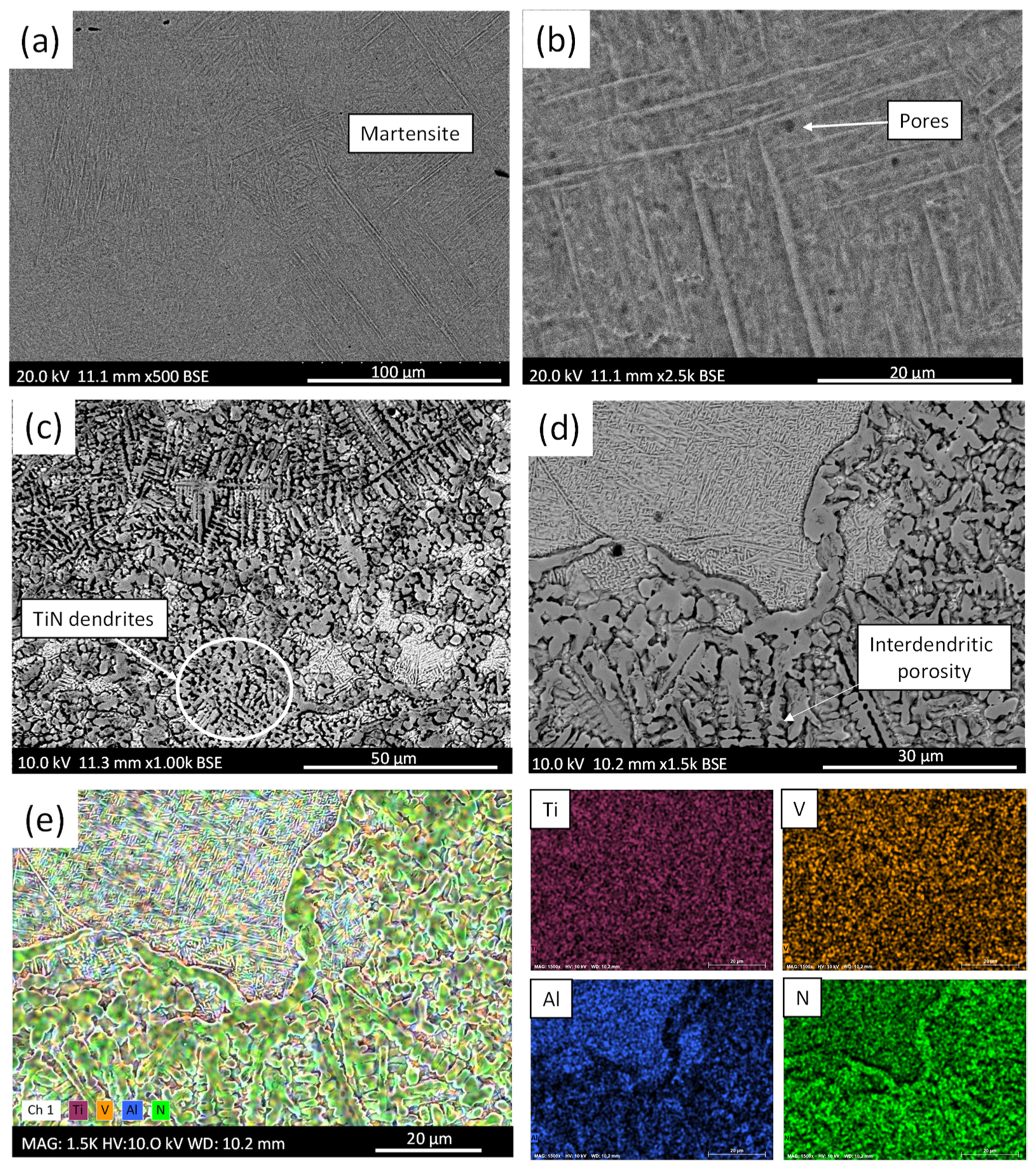
  • The microstructure of the printed material was evaluated using XRD and SEM, and it was concluded that a martensitic Ti6Al4V microstructure was formed in the unreinforced material, and TiN dendrites were gradually introduced into an α + β basketweave titanium matrix with the formation of a minor Ti2N.
  • The porosity levels and the reinforcement percentages increased with the presence of nitrogen in the printing chamber, with measurements ranging from 7 to 12% and from 15 to 25%, respectively. The voids ranged in size from 5 to 300 µm and most pores had sizes between 20 and 40 µm.
  • The defectology present in the materials was analyzed. The main defects found in the printed parts were a lack of fusion voids, spherical pores, and interdendritic porosity.
  • The microhardness of the Ti6Al4V/TiN was 850 ± 350 HV0.1, which is 100% higher than the unreinforced Ti6Al4V. The nanohardness and elastic modulus of Ti/TiN were ×3 and ×1.5 higher than those of the unreinforced Ti6Al4V. This makes L-PBF a promising technique to obtain harder multi-grade Ti-TiN for customized medical applications, such as hip implants.
  • A scaled-up proof of concept of a hip implant stem was printed using the nitriding method; the part was functionalized by gradually changing the material from unreinforced Ti6Al4V at the bottom to Ti6Al4V/TiN composite material at the top, where fretting corrosion occurs and a material with a higher hardness and corrosion-wear resistance is required.

Author Contributions

Conceptualization, J.R., P.R. and A.R.; methodology, C.S.d.R.C., A.R. and P.R.; investigation, C.S.d.R.C., A.R., P.R., V.B. and J.B.; resources, A.R., P.R., B.T. and J.R.; data curation C.S.d.R.C., A.R., P.R. and V.B.; writing—original draft preparation, C.S.d.R.C. and A.R; writing—review and editing, C.S.d.R.C., A.R., P.R., J.B., V.B., B.T. and J.R.; supervision, A.R., P.R., B.T. and J.R.; project administration, J.R. and P.R.; funding acquisition, J.R., B.T. and P.R. All authors have read and agreed to the published version of the manuscript.

Funding

This research was funded by Agencia Estatal de Investigación, grant number PID2021-124341OB-C21, PID2021-123891OB-I00, TED2021-129849B-I00, and Proyecto Puente 2021, URJC (2022/00004/016).

Institutional Review Board Statement

Not applicable.

Informed Consent Statement

Not applicable.

Data Availability Statement

Data are contained within the article.

Conflicts of Interest

The authors declare no conflict of interest. The funders had no role in the design of the study; in the collection, analyses, or interpretation of data; in the writing of the manuscript; or in the decision to publish the results.

References

  1. Singh, N.; Hameed, P.; Ummethala, R.; Manivasagam, G.; Prashanth, K.G.; Eckert, J. Selective laser manufacturing of Ti-based alloys and composites: Impact of process parameters, application trends, and future prospects. Mater. Today Adv. 2020, 8, 100097. [Google Scholar] [CrossRef]
  2. Huang, N.; Leng, Y.X.; Ding, P.D. Surface Engineered Titanium Alloys for Biomedical Devices; Woodhead Publishing: Cambridge, UK, 2010; ISBN 9781845695378. [Google Scholar]
  3. Grabarczyk, J.; Gaj, J.; Pazik, B.; Kaczorowski, W.; Januszewicz, B. Tribocorrosion behavior of Ti6Al4V alloy after thermo-chemical treatment and DLC deposition for biomedical applications. Tribol. Int. 2021, 153, 106560. [Google Scholar] [CrossRef]
  4. Shi, B.; Huang, S.; Zhu, P.; Xu, C.; Guo, P.; Fu, Y. In-situ TiN reinforced composite coatings prepared by plasma spray welding on Ti6Al4V. Mater. Lett. 2020, 276, 128093. [Google Scholar] [CrossRef]
  5. Song, C.; Liu, M.; Deng, Z.Q.; Niu, S.P.; Deng, C.M.; Liao, H.L. A novel method for in-situ synthesized TiN coatings by plasma spray-physical vapor deposition. Mater. Lett. 2018, 217, 127–130. [Google Scholar] [CrossRef]
  6. Zhao, X.; Zhang, P.; Wang, X.; Chen, Y.; Liu, H.; Chen, L.; Sheng, Y.; Li, W. In-situ formation of textured TiN coatings on biomedical titanium alloy by laser irradiation. J. Mech. Behav. Biomed. Mater. 2018, 78, 143–153. [Google Scholar] [CrossRef] [PubMed]
  7. Yuan, S.; Lin, N.; Zou, J.; Lin, X.; Liu, Z.; Yu, Y.; Wang, Z.; Zeng, Q.; Chen, W.; Tian, L.; et al. In-situ fabrication of gradient titanium oxide ceramic coating on laser surface textured Ti6Al4V alloy with improved mechanical property and wear performance. Vacuum 2020, 176, 109327. [Google Scholar] [CrossRef]
  8. Avila, J.D.; Stenberg, K.; Bose, S.; Bandyopadhyay, A. Hydroxyapatite reinforced Ti6Al4V composites for load-bearing implants. Acta Biomater. 2021, 123, 379–392. [Google Scholar] [CrossRef]
  9. Liu, S.; Shin, Y.C. Additive manufacturing of Ti6Al4V alloy: A review. Mater. Des. 2019, 164, 107552. [Google Scholar] [CrossRef]
  10. Zeng, C.; Wen, H.; Bellamy, H.; Sprunger, P.T.; Schilling, P.J.; Guo, S.M. Titanium and nitrogen interactions under laser additive manufacturing conditions. Surf. Coat. Technol. 2019, 378, 124955. [Google Scholar] [CrossRef]
  11. Chan, C.W.; Quinn, J.; Hussain, I.; Carson, L.; Smith, G.C.; Lee, S. A promising laser nitriding method for the design of next generation orthopaedic implants: Cytotoxicity and antibacterial performance of titanium nitride (TiN) wear nano-particles, and enhanced wear properties of laser-nitrided Ti6Al4V surfaces. Surf. Coat. Technol. 2021, 405, 126714. [Google Scholar] [CrossRef]
  12. Rasiya, G.; Shukla, A.; Saran, K. Additive Manufacturing-A Review. Mater. Today Proc. 2021, 47, 6896–6901. [Google Scholar] [CrossRef]
  13. Zhu, J.; Zhou, H.; Wang, C.; Zhou, L.; Yuan, S.; Zhang, W. A review of topology optimization for additive manufacturing: Status and challenges. Chin. J. Aeronaut. 2021, 34, 91–110. [Google Scholar] [CrossRef]
  14. Fereiduni, E.; Ghasemi, A.; Elbestawi, M. Selective laser melting of aluminum and titanium matrix composites: Recent progress and potential applications in the aerospace industry. Aerospace 2020, 7, 77. [Google Scholar] [CrossRef]
  15. Zhong, C.; Liu, J.; Zhao, T.; Schopphoven, T.; Fu, J.; Gasser, A.; Schleifenbaum, J.H. Laser metal deposition of Ti6Al4V-A brief review. Appl. Sci. 2020, 10, 764. [Google Scholar] [CrossRef]
  16. Lawrence, J.R.; Pou, J.; Low, D.K.Y.; Toyserkani, E. Advances in Laser Materials Processing; Woodhead Publishing: Cambridge, UK, 2010; ISBN 9781845694746. [Google Scholar]
  17. Attar, H.; Ehtemam-Haghighi, S.; Kent, D.; Dargusch, M.S. Recent developments and opportunities in additive manufacturing of titanium-based matrix composites: A review. Int. J. Mach. Tools Manuf. 2018, 133, 85–102. [Google Scholar] [CrossRef]
  18. Bedmar, J.; Riquelme, A.; Rodrigo, P.; Torres, B.; Rams, J. Comparison of Different Additive Manufacturing Methods for 316L Stainless Steel. Materials 2021, 14, 6504. [Google Scholar] [CrossRef]
  19. Prabakaran, M.P.; Kannan, G.R. Optimization of CO2 Laser Beam Welding Process Parameters to Attain Maximum Weld Strength in Dissimilar Metals. Mater. Today Proc. 2018, 5, 6607–6616. [Google Scholar] [CrossRef]
  20. Lee, H.; Lim, C.H.J.; Low, M.J.; Tham, N.; Murukeshan, V.M.; Kim, Y.-J. Lasers in additive manufacturing: A review. Int. J. Precis. Eng. Manuf. Technol. 2017, 4, 307–322. [Google Scholar] [CrossRef]
  21. Bedmar, J.; de la Pezuela, J.; Riquelme, A.; Torres, B.; Rams, J. Impact of Remelting in the Microstructure and Corrosion Properties of the Ti6Al4V Fabricated by Selective Laser Melting. Coatings 2022, 12, 284. [Google Scholar] [CrossRef]
  22. Aversa, A.; Saboori, A.; Librera, E.; de Chirico, M.; Biamino, S.; Lombardi, M.; Fino, P. The role of Directed Energy Deposition atmosphere mode on the microstructure and mechanical properties of 316L samples. Addit. Manuf. 2020, 34, 101274. [Google Scholar] [CrossRef]
  23. Wei, W.; Wu, W.; Fan, S.; Duan, X. In-situ laser additive manufacturing of Ti6Al4V matrix composites by gas–liquid reaction in dilute nitrogen gas atmospheres. Mater. Des. 2021, 202, 109578. [Google Scholar] [CrossRef]
  24. Riquelme, A.; Rodrigo, P.; Escalera-Rodriguez, M.D.; García-Fogeda, P.; Rams, J. Influence of the feed powder composition in mechanical properties of ALN-nano-reinforced aluminium composites coatings deposited by reactive direct laser deposition. Metals 2020, 10, 926. [Google Scholar] [CrossRef]
  25. Abenojar, J.; Velasco, F.; Bautista, A.; Campos, M.; Bas, J.A.; Torralba, J.M. Atmosphere influence in sintering process of stainless steels matrix composites reinforced with hard particles. Compos. Sci. Technol. 2003, 63, 69–79. [Google Scholar] [CrossRef]
  26. Riquelme, A.; Rodrigo, P.; Escalera-Rodriguez, M.D.; Rams, J. Effect of the process parameters in the additive manufacturing of in situ Al/AlN samples. J. Manuf. Process. 2019, 46, 271–278. [Google Scholar] [CrossRef]
  27. Rodrigo, P.; Riquelme, A.; Escalera-Rodriguez, M.D.; Rams, J. Procedimiento de Obtención de Material Compuesto Al/AlN o Ti/TiN, Material Compuesto Al/AlN o Ti/TiN Obtenible Según Dicho Procedimiento y uso del Mismo en Revestimientos. Patent ES2598727A2, 14 September 2017. [Google Scholar]
  28. Mridha, S.; Baker, T.N. Crack-free hard surfaces produced by laser nitriding of commercial purity titanium. Mater. Sci. Eng. A 1994, 188, 229–239. [Google Scholar] [CrossRef]
  29. Na, T.W.; Kim, W.R.; Yang, S.M.; Kwon, O.; Park, J.M.; Kim, G.H.; Jung, K.H.; Lee, C.W.; Park, H.K.; Kim, H.G. Effect of laser power on oxygen and nitrogen concentration of commercially pure titanium manufactured by selective laser melting. Mater. Charact. 2018, 143, 110–117. [Google Scholar] [CrossRef]
  30. Choroszyński, M.; Choroszyński, M.R.; Skrzypek, S.J. Biomaterials for hip implants—Important considerations relating to the choice of materials. Bio-Algorithms Med-Syst. 2017, 13, 133–145. [Google Scholar] [CrossRef]
  31. Blunt, L.; Bills, P.; Jiang, X.; Hardaker, C.; Chakrabarty, G. The role of tribology and metrology in the latest development of bio-materials. Wear 2009, 266, 424–431. [Google Scholar] [CrossRef]
  32. Geringer, J.; Kim, K.; Pellier, J.; Macdonald, D.D. Fretting corrosion processes and wear mechanisms in medical implants. In Bio-Tribocorrosion in Biomaterials and Medical Implants; Elsevier: Amsterdam, The Netherlands, 2013; pp. 45–73. [Google Scholar]
  33. Maja, M.E.; Falodun, O.E.; Obadele, B.A.; Oke, S.R.; Olubambi, P.A. Nanoindentation studies on TiN nanoceramic reinforced Ti–6Al–4V matrix composite. Ceram. Int. 2018, 44, 4419–4425. [Google Scholar] [CrossRef]
  34. Robinson, J.H.; Ashton, I.R.T.; Jones, E.; Fox, P.; Sutcliffe, C. The effect of hatch angle rotation on parts manufactured using selective laser melting. Rapid Prototyp. J. 2019, 25, 289–298. [Google Scholar] [CrossRef]
  35. Al-Rubaie, K.S.; Melotti, S.; Rabelo, A.; Paiva, J.M.; Elbestawi, M.A.; Veldhuis, S.C. Machinability of SLM-produced Ti6Al4V titanium alloy parts. J. Manuf. Process. 2020, 57, 768–786. [Google Scholar] [CrossRef]
  36. de Rojas Candela, C.S.; Riquelme, A.; Rodrigo, P.; Rams, J. Carrying Gas Influence and Fabrication Parameters Impact in 3D Manufacturing of In Situ TiN-Ti Composites by Direct Laser Deposition. Met. Mater. Int. 2023, 29, 591–606. [Google Scholar] [CrossRef]
  37. Gil, F.J.; Ginebra, M.P.; Manero, J.M.; Planell, J.A. Formation of α-Widmanstätten structure: Effects of grain size and cooling rate on the Widmanstätten morphologies and on the mechanical properties in Ti6Al4V alloy. J. Alloys Compd. 2001, 329, 142–152. [Google Scholar] [CrossRef]
  38. Sieniawski, J.; Ziaja, W.; Kubiak, K.; Motyk, M. Microstructure and Mechanical Properties of High Strength Two-Phase Titanium Alloys. In Titanium Alloys—Advances in Properties Control; InTech: London, UK, 2013. [Google Scholar]
  39. Barink, M.; Meijers, H.; Spruit, M.; Fankhauser, C.; Verdonschot, N. How close does an uncemented hip stem match the final rasp position? Acta Orthop. Belg. 2004, 70, 534–539. [Google Scholar]
  40. Bartolomeu, F.; Costa, M.M.; Alves, N.; Miranda, G.; Silva, F.S. Additive manufacturing of NiTi-Ti6Al4V multi-material cellular structures targeting orthopedic implants. Opt. Lasers Eng. 2020, 134, 106208. [Google Scholar] [CrossRef]
Figure 1. (a) Image of the L-PBF multigrade Ti6Al4V/TiN sample; (b) XRD patterns of multigrade Ti/TiN and unreinforced Ti6Al4V.
Coatings 14 00090 g001
Figure 2. (a) Microstructure of the material manufactured with Ar at lower magnification; (b) martensitic microstructure in unreinforced Ti6Al4V sample at higher magnification; (c) microstructure of the material manufactured with Ar:N2 at lower magnification; (d) TiN dendrites on the titanium matrix at higher magnification; (e) EDS Element map of (d).
Coatings 14 00090 g002
Figure 3. Microstructure of the sample manufactured with a mixture of argon and nitrogen in the transition zone: (a) combined layers of Ti alloy and TiN; (b) TiN dendrites on Ti6Al4V matrix (a); (c) detail of the three different zones identified; (d) magnification of zone 2 of (c).
Coatings 14 00090 g003
Figure 4. Histogram of porosity distribution for the multigrade Ti6Al4V/TiN sample.
Coatings 14 00090 g004
Figure 5. (a) Microhardness and the percentage of reinforcement along the building direction. (b) Load–displacements curves at different zones of multigrade Ti/TiN and unreinforced Ti6Al4V; (c) Hardness and elastic modulus of multigrade Ti/TiN and unreinforced Ti6Al4V.
Coatings 14 00090 g005
Figure 6. (a) Digital 3D object of stem part scaled-up proof of concept with support material in the slicer software; (b) additive manufactured part with support material; (c) final hip implant stem manufactured with two different materials.
Coatings 14 00090 g006
Figure 7. (a) Cross-section of the hip implant stem showing its porosity; (b) cut at the interface between the two materials of the stem.
Coatings 14 00090 g007
Figure 8. (a) SEM image of the top part of the scaled-up proof of concept stem; (b) detail of (a); (c) cross-section of the part in the nitrided zone; (d) microstructure of the stem at the interface region between the two materials; (e) detail of (d).
Coatings 14 00090 g008
Figure 9. (a) Scheme of the microhardness indentations’ location along the manufactured hip implant stem; (b) Vickers microhardness evolution along the building direction.
Coatings 14 00090 g009
Disclaimer/Publisher’s Note: The statements, opinions and data contained in all publications are solely those of the individual author(s) and contributor(s) and not of MDPI and/or the editor(s). MDPI and/or the editor(s) disclaim responsibility for any injury to people or property resulting from any ideas, methods, instructions or products referred to in the content.

