Article

Preparation and Characterization of Polymer-Based Electrospun Nanofibers for Flexible Electronic Applications

by
Gopiraman Mayakrishnan
1,†,
Ramkumar Vanaraj
2,†,
Takayasu Kitauchi
1,
Rajakumar Kanthapazham
3,
Seong Cheol Kim
2 and
Ick Soo Kim
1,*
1
Nano Fusion Technology Research Group, Institute for Fiber Engineering (IFES), Interdisciplinary Cluster for Cutting Edge Research (ICCER), Shinshu University, Tokida 3-15-1, Ueda 386-8567, Japan
2
School of Chemical Engineering, Yeungnam University, Gyeongsan 38541, Republic of Korea
3
Nanotechnology Research & Education Centre, South Ural State University, Chelyabinsk 454080, Russia
*
Author to whom correspondence should be addressed.
These authors contributed equally to this work.
Coatings 2024, 14(1), 35; https://doi.org/10.3390/coatings14010035
Submission received: 30 November 2023 / Revised: 22 December 2023 / Accepted: 25 December 2023 / Published: 27 December 2023
(This article belongs to the Special Issue Advanced Materials for Electrocatalysis and Energy Storage)

Abstract

:
This study was undertaken to synthesize and characterize PVDF/CB (polyvinylidene fluoride/carbon block) nanofiber composites for flexible, wearable electronic applications. Nanofibers were produced by electrospinning method and used to produce thin films. Fiber surface morphologies were investigated by FE-SEM and HR-TEM, crystalline structures by FT-IR and P-XRD, and thermal characteristics by TGA and DSC. The prepared materials are thermally stable up to 390 °C. Mechanical properties were ascertained using tensile characteristics, and results showed that the addition of carbon black (CB) powder to PVDF polymer solution decreased Young’s modulus values and reduced the dielectric constant of PVDF nanofiber films. The obtained dielectric constants of nanofibers loaded with various concentrations of CB were found from 1.4 to 2.0. Flexible electronics materials are essential for the production of wearable electronics and various biomedical engineering applications. The PVDF/CB nanofibers containing 1% showed maximum Young’s moduli of 101.29 ± 15.94. Nanofiber thin films offer various advantages, including simplicity of manufacture, low power consumption, flexibility, and exceptional stability, all of which are crucial for flexible, wearable device applications.

1. Introduction

The sophistication of smart electronics and healthcare robots has advanced significantly over recent years. Wearable gadgets, which are crucial components of robots, must not only be highly sensitive but also be flexible and safe for human use [1,2,3,4]. Silicone rubber and polydimethylsiloxane have been employed as innovative materials, but their sensitivities are lacking. It has been demonstrated that increasing the porosity of the dielectric layer, lowering the stiffness of a material, increasing material deformability, and enhancing the structural design of the dielectric layer may all enhance a material’s outcome efficiency [5]. In this context, fabrics comprised of nano- and microfibers are becoming more popular. Textile-based materials are durable, breathable, and flexible, which makes them ideal for extended usage, and are used to make pressure sensors [6,7,8]. PVDF (polyvinylidene difluoride, (C2H2F2)n) has excellent thermal stability and has been used by many researchers in this area because of its exceptional qualities, particularly its chemical resistance. PVDF is a semi-crystalline polymer which is usually produced in the form of nonpolar crystals but can be produced in a piezoelectric form by stretching or a ferroelectric form by heating Beta crystals. These properties stem from the strong electronegativity of fluorine atoms. Furthermore, Beta crystals are piezoelectric because when stress is applied, PVDF polymer chains produce parallel dipoles, and, thus, a net dipole moment. On the other hand, ferroelectricity is the result of spontaneous polarization that can be reversed by applying an external voltage. As a result, PVDF has attracted attention recently as a material for piezoelectric sensors [9] and electromechanical actuators [10], and, at a research level, for organic solar cells.
Carbon black (CB) is commonly dispersed in electrical media to modify physical characteristics. CB is produced by partially burning oil and is difficult to process because of its dusty nature. The principal applications for carbon black are in automotive and aircraft tires and industrial belts and hoses. CB particles are 3–500 nm and confer the capacity to resist UV degradation on polymeric media. The purity of CB and its surface properties depend on the manufacturing procedure. For instance, thermal CB (a large particle form) is produced by thermally breaking down gases, usually methane. Acetylene CB is created when acetylene is subjected to exothermic breakdown and is distinguished by its extreme purity. Other forms of CB include contact black and furnace black [11].
Nanofibers are fine fibrous materials <500 nm thick, which is around 1/200th of the thickness of a human hair and may be natural or synthetic, inorganic, or organic [12,13,14]. Because of their high specific surface areas, molecular arrangement effects, and enhanced mechanical, thermal, and optical properties, nanofibers have a wide range of applications, including in breathable and waterproof clothing. In addition, they are being considered for medical (e.g., artificial blood vessels) and health monitoring applications and in the environmental domain for filters and biosensors [15]. In particular, nanofibers have many possible uses in the biomedical industry, including as scaffolds for cartilage, skin, and capillaries in regenerative medicine. Scaffolding materials used to rebuild diverse organs must be stable and safe for use in the human body and possess suitable absorbability, porosities, mechanical strengths, oxygen permeabilities, and cell adhesion characteristics. Nonwoven textiles are considered to be suitable for drug-containing wound dressings if they can absorb 20 times their weight of water, but nanofibers are able to absorb twice this amount. Furthermore, nanofibers produce a structure similar to skin, which speeds up recovery.
Several techniques, such as electrospinning, melt-blowing, and the sea-island conjugate spinning method, have been developed to manufacture nanofibers [16,17,18]. However, electrospinning provides the most straightforward, affordable, and straightforward means of producing synthetic and natural nanofibers [19]. This technique entails filling a syringe with a polymer solution and applying a high voltage [20,21,22,23,24]. The nanofibers are then produced by an electrostatic effect [14]. The effects of electrospinning parameters have been well explained by several researchers, and current studies focus on applications and processing improvements [25,26,27,28,29]. Prominent industrial applications include filters and masks [30,31,32], electrodes for batteries and capacitors [33,34], materials for scaffolding in regenerative medical engineering [35,36], and wound dressings [37]. The nanostructures produced by electrospinning include fiber, Janus, and three-layer core–shell structures, which include tree-like and other complex structures. In addition, the technology is rapidly expanding to include more complicated nanofiber structures, such as coaxial, side-by-side, and triaxial forms. Furthermore, nanofibers can be functionalized by adding certain substances to the base polymer. These can be added by simple mixing, which is the method most often used [38]. The remarkable adaptability and flexibility of electrospinning have been well demonstrated. Fibers have been produced with special benefits, such as the ability to produce multidimensional structures in one to three dimensions or continuous, homogeneous nanofibers of required morphologies from many synthetic and natural polymers. Consequently, nanofibers can act as excellent carriers for bioactive substances as they can be targeted to specific locations and tailored to release drugs in a prescribed manner.
In the present study, we sought to produce nanofibers from PVDF, a material recently popularized by its electronic properties. PVDF is a semi-crystalline polymer with good heat and high-temperature stability. However, to reduce its Young’s modulus to match end use requirements, we loaded PVDF with different amounts of CB.

2. Experimental

2.1. Materials

As a polymeric material for creating nanofibers, polyvinylidene fluoride (PVDF; Mw; 350,000, Sigma-Aldrich, St. Louis, MO, USA) was used. The solvent acetone and DMF were procured from Wako, Japan (99.9%), and Sigma-Aldrich in the United States provided carbon black (CB) as the solute (40 μm, 150–250 m2/g, >100 ppm). The materials were used as purchased without further purification.

2.2. Instrumentations

Sample surfaces and morphologies were examined by transmission electron microscopy (TEM; JEM-2100, JEOL, Tokyo, Japan) and scanning electron microscopy (SEM; JSM-6010LA, JEOL, Tokyo, Japan). FT-IR (Fourier-Transform Infrared Spectroscopy, FT/IR-6600, JASCO, Tokyo, Japan) (range of 4000 to 400 cm1, resolution 4 cm1) was used to confirm the identities of the manufactured materials and the background and samples in reflection mode. The crystal structures of samples were studied by XRD (X-ray diffraction, MiniFlex300, Rigaku, Shibuya, Japan). The thermal properties of nanofibers were investigated by thermal gravimetric analysis (TGA 8120, Rigaku, Tokyo, Japan) at 10 °C/min over the temperature range 0 to 600 °C. Differential scanning calorimetry (DSC) was performed at 5 °C/min using a Shimadzu (Kyoto, Japan) instrument in the temperature range 0 to 180 °C. A thermomechanical analyzer (TMA; Tokyo, SS6100, SII) was used to determine fiber thermal shrinkages.

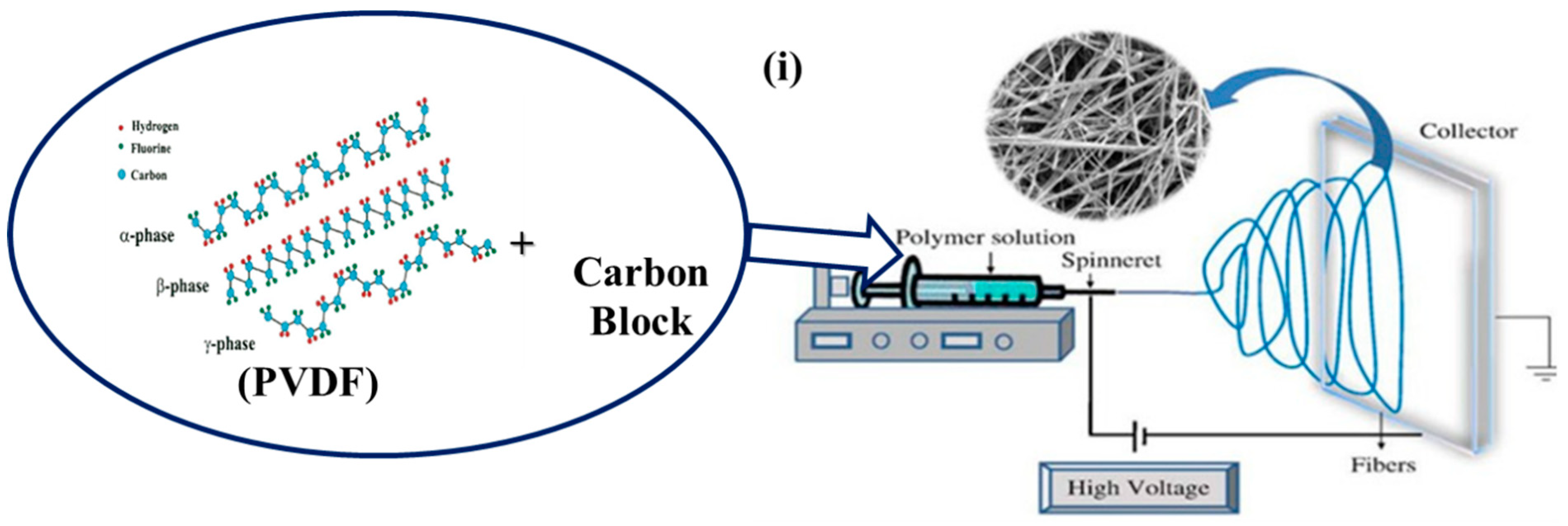
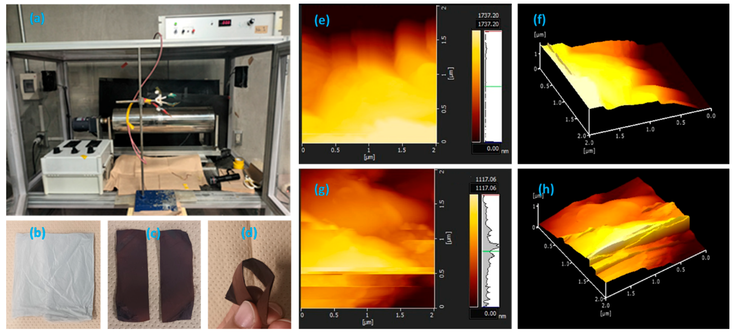
2.3. Electrospinning Method

DMF and acetone were mixed at a ratio of 2:3 (v/v), and 25% of PVDF was then added with stirring at 80 °C. CB 1 wt%, 3 wt%, 5 wt%, 7 wt%, or 10 wt% was then added with mixing. The electrospinning device was equipped with a high-voltage supply of maximum output 100 kV (Har-100*12, Matsusada Co., Ltd., Tokyo, Japan) and a grounded rotating drum collector coated with oiled paper. Electrospinning was performed using a 20 mL plastic syringe fitted with a capillary tip of inner diameter 0.6 mm. There was a 15 cm gap between the tip collectors for both polymer solutions. Spinning was performed using an applied voltage of 12 kV. The nonwoven fabric manufactured was fastened with a ceramic plate in a high-speed electric furnace (SUPER-BURN: NHV-1515D, Motoyama, Japan) at 0 °C for 6 h. A schematic representation of the crystalline structure of PVDF and the preparation of PVDF/CB are provided in Figure 1i–iii [37].

2.4. Mechanical Studies

The tension control decreases stress to 0.1 MPa and increases the heating rate to 5 °C/min, and TMA measurements were taken throughout a temperature range of 20–200 °C. A Tensilon universal testing unit (RTC-1250A, A&D Co., Ltd. (Tokyo, Japan)) was used for the mechanical testing of prepared samples. The following calculations, (1) and (2), were used to compute stress and strain after the tension [29,37].
ε = l l
σ = F A
where ε is strain, σ is stress. Also, l is the original length of the specimen, and ∆l is the change in length, F is power, A is the cross-sectional area.
The dielectric constant was measured by impedance measuring equipment (Solartron-1260/1296, Analytical, Farnborough, UK). The dielectric constant was measured using the two-terminal approach, which involved sandwiching the nanofiber nonwoven fabric between two electrodes.

3. Results and Discussion
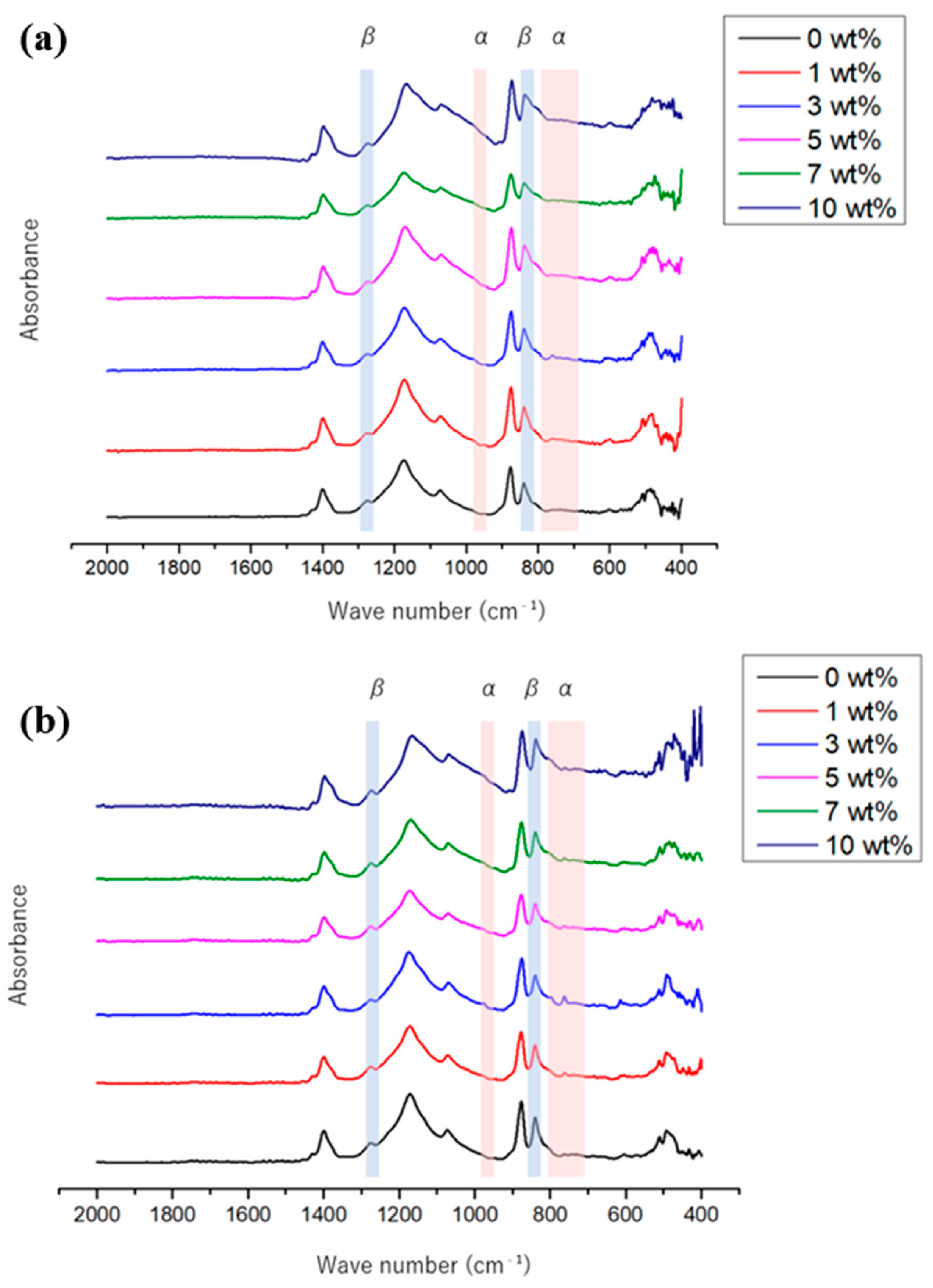
3.1. FT-IR Analysis

FT-IR analysis was utilized to establish the existence of functional groups in the nanofiber material and to determine its crystallinity. The FT-IR spectra of the pre- and post-stabilized PVDF/CB nanofibers are displayed in Figure 2a,b. The peak at 765 cm−1, 795 cm−1, and 975 cm−1 denotes the crystal phase, whereas the peak at 840 cm−1 and 1278 cm−1 of the generic PVDF molecule indicates the crystal phase [39]. When CB is added to PVDF, the peak intensity of the α crystal phase increases while the peak intensity of the β crystal phase decreases, as seen in Figure 2b. The findings point to a shift in the crystalline phase in PVDF. The β crystalline phase fraction F of each sample (β) was measured using FT-IR absorbance, which allowed for the calculation of the crystallinity of the nanofiber material. Assuming that the absorbance follows the Lambert–Beer equation, F(β) is Formula (3), computed using [40,41,42]:
F ( β ) = A ( β ) 1.3 A α + A ( β )
Absorbances at 765 and 840 cm−1, respectively, are represented by the variables A(α) and A(β), and the constant 1.3 was derived from the absorption coefficient at the appropriate wave number [40,41,42]. For PVDF nanofibers, obtained F(β) values were 81.1%, 74.0%, 68.9%, 58.6%, 56.0%, and 50.6%.
The FT-IR spectra of thermally stabilized PVDF nanofibers and PVDF/CB nanofibers are given in Figure 2b and show that β crystalline phase peak intensity increased at 840 and 1278 cm−1. The obtained F(β) values of stabilized PVDF/CB were 4.0%, 75.5%, 64.6%, 62.3%, 59.2%, and 52.7%, respectively. Adding CB reduced the β crystalline phase, much like it did before thermal stabilization. The results are comparable to DSC results and show that the presence of CB increases the amorphous character of PVDF. Additionally, PVDF/CB nanofibers and thermally stabilized nanofibers showed a slight increase in the β crystalline phase, presumably because thermal stabilization reduced the amorphous fraction but increased the crystalline portion.

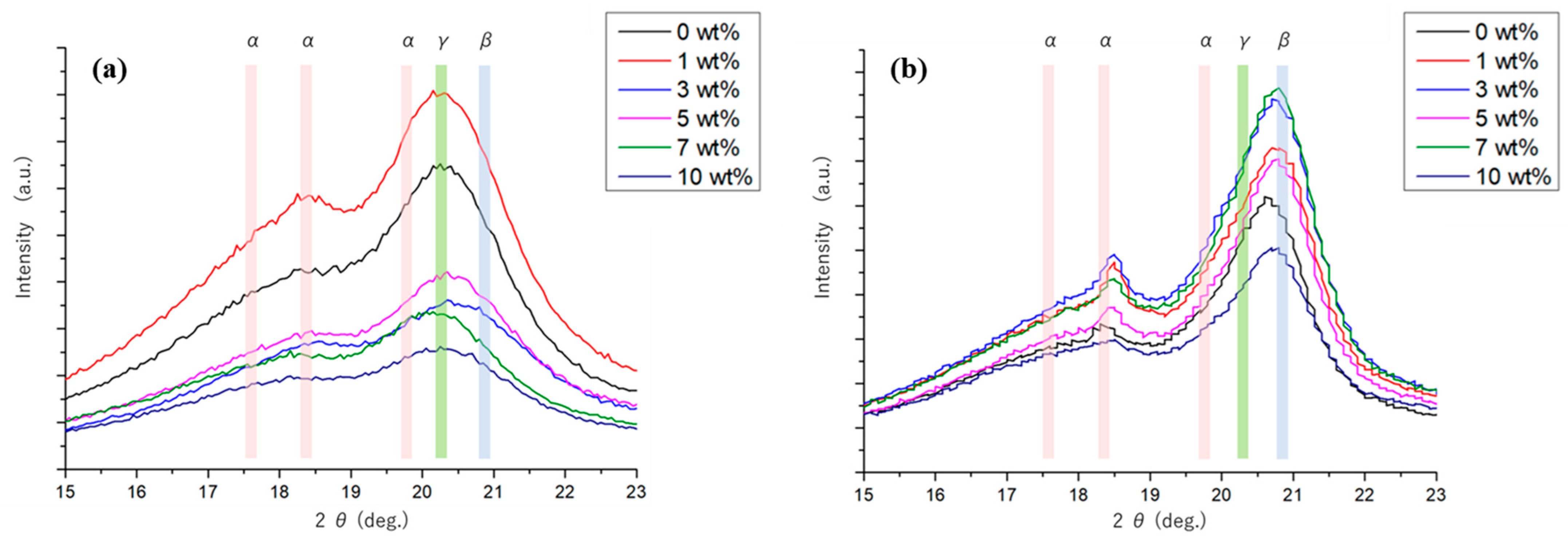
3.2. P-XRD Results before and after Stabilization of PVDF/CB

Figure 3a,b shows powder XRD spectra of PVDF and PVDF/CB nanofibers before and after thermal stabilization. The α crystalline phase of PVDF was observed between 1.7.6° and 18.4°, whereas the β crystalline phase was observed at 20.9° [43,44,45,46]. Increasing the amount of CB reduced peak intensities. In particular, the peak at 18.4°, which represents the crystal phase, reduced noticeably. In addition, the peak at 20.9°, corresponding to the crystal phase diminished. These findings confirmed that adding CB reduced the crystalline fraction and increased the amorphous fraction. In addition, a peak corresponding to the γ crystal phase of PVDF was observed for all nanofibers at 20.3° [43]. Because the crystal phase has an intermediate structure between the crystal phase and the crystal phase, it can be seen that the PVDF nanofibers and PVDF/CB nanofibers before heat treatment are mostly constituted of the crystal phase and the crystal phase.
The XRD patterns of thermally stabilized PVDF nanofibers and PVDF/CB nanofibers are shown in Figure 3b. According to the results, the peak at 18.4° represents the α crystalline phase, whereas the peak at 20.9° represents the β crystalline phase. Similarly, the peak at 20.3° denotes the γ crystalline phase, and this peak shifts to 20.9° after PVDF/CB nanofiber stabilization. Most of the intermediate γ crystalline phase changed to become the β crystalline phase after stabilization. Furthermore, when the crystalline phase’s peak intensity grows, the amorphous fraction drops, indicating that the crystalline phase has risen. DSC, FT-IR, and this, similar to how thermal stabilization decreases the amorphous portion, prove that the crystalline phase has increased.
It is also expected that both the crystalline structures of fibers and the fiber morphologies may play a crucial role in the mechanical properties of nanofiber filaments. PVDF shows four polymorphs (α, β, γ, and δ), depending on the thermal treatment. The most studied and important polymorphs are α and β phases. Figure 3 shows WAXD patterns of PVDF nonwoven nanofibers and PVDF nanofiber filaments prepared with different numbers of twists. The PVDF nonwoven nanofibers showed the characteristic peaks at 2θ = 18.5°, 20.0°, and 20.6°, corresponding to α(202), α(111), and β(200/110) phases, respectively, indicating the coexistence of the α phase and the β phase in the PVDF nonwoven nanofibers. On the contrary, in the case of PVDF nanofiber filaments, the strong characteristic peak at 2θ = 20.6° was drastically reduced, whereas a new peak appeared at 2θ = 20.0°, which corresponds to the α(111) phase that became evident, suggesting that the transformation from β to α phase occurred by the sheer force driven by twisting.

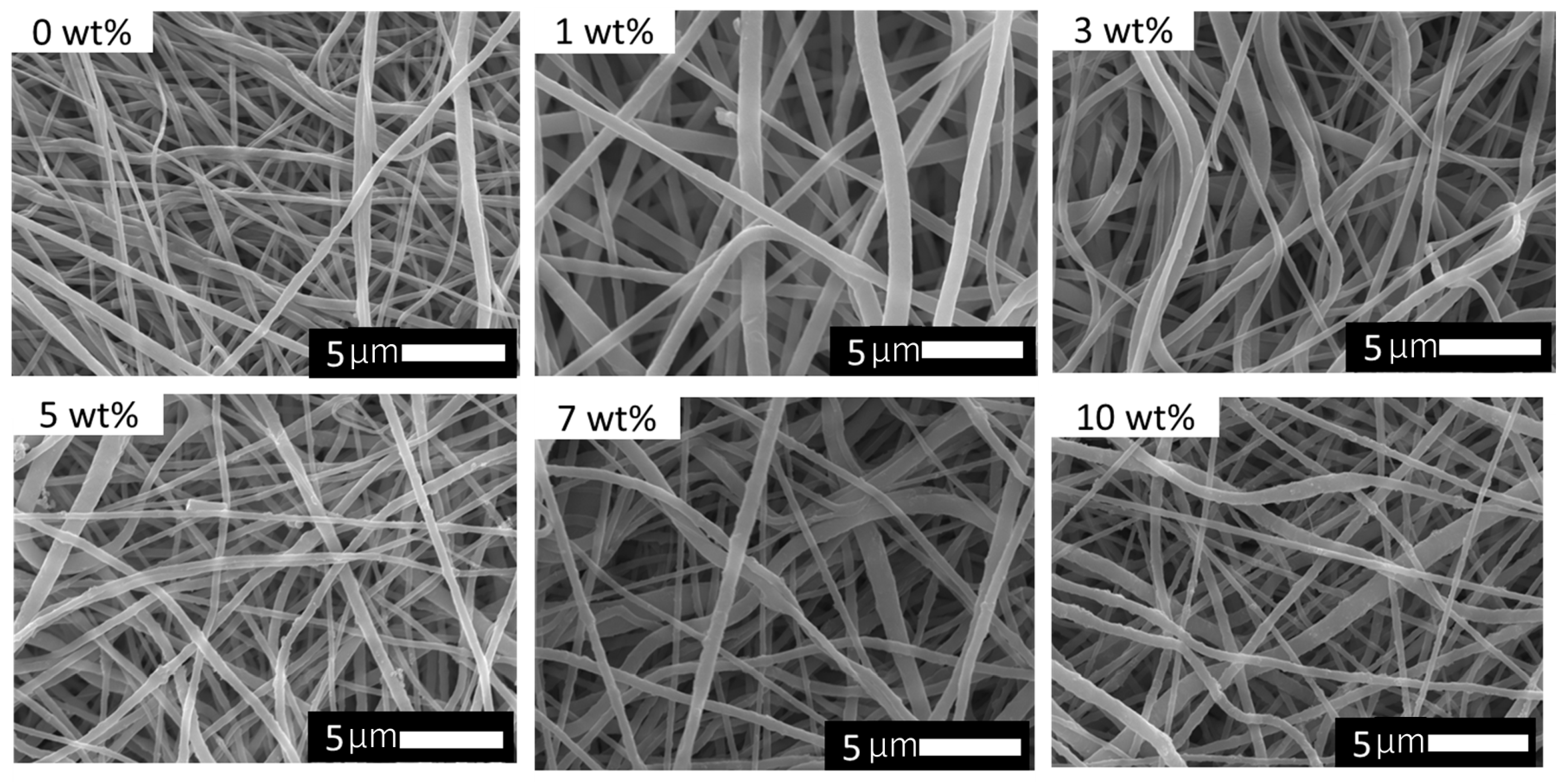
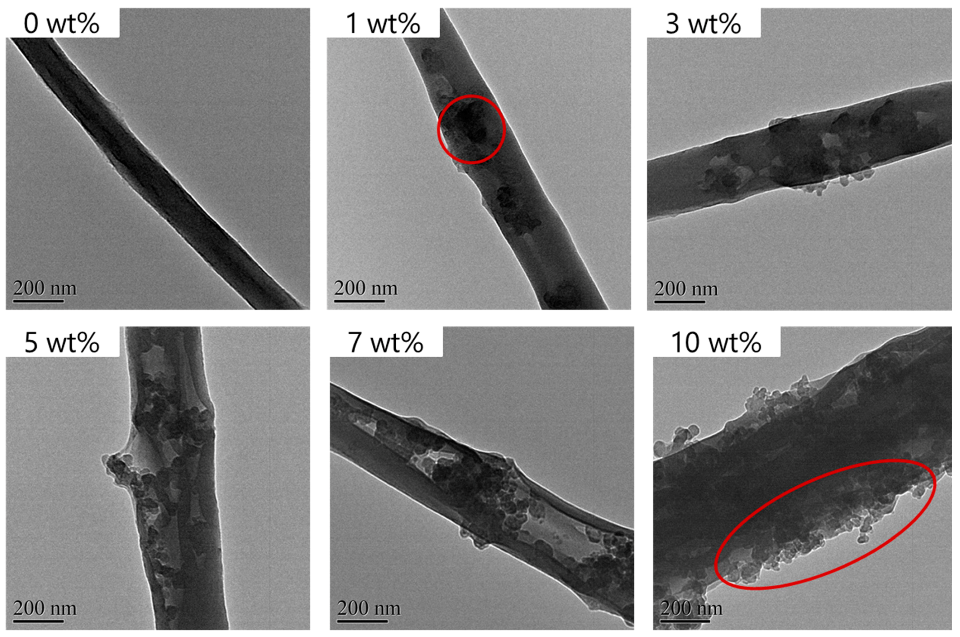
3.3. Surface Morphology Analysis

FE-SEM images of stabilized PVDF/CB nanofibers are shown in Figure 4. The images show clean surfaces without beads but increased surface roughness after adding CB. The images are representative of 50 randomly selected fibers. The average fiber diameter of PVDF nanofibers at 1%, 3%, 5%, 7%, and 10% CB were 450, 415, 432, 404, and 413 nm, respectively. That is, CB loadings did not significantly affect fiber diameter. Images of corresponding thermally stabilized nanofibers are shown in Figure 4. Their surfaces were rougher than those of non-thermally stabilized fibers due to fiber thermal contraction during thermal stabilization. The twisted character on the nanofiber surface is the outcome. The average fiber diameters of thermostabilized nanofibers containing CB at 1%, 3%, 5%, 7%, and 10% were 394, 553, 447, 422, 493, and 468 nm; that is, average fiber diameters were increased by thermal stabilization and possibly shrinkage.
HR-TEM was used to investigate the surface morphologies of nanofibers further (Figure 5). Increasing the CB loading caused more aggregation and increased fiber roughness. At the highest loading of 10%, fibers were obviously rougher.
Figure 6a represents the machine setup of the electrospinning, the prepared PVDF/CB nanofiber before and after stabilization is depicted in Figure 6b,c, and the flexibility of the nanofiber is shown in Figure 6d. The surface roughness of the PVDF/CB nanofiber composites was analyzed by AFM analysis (Figure 6e–h). The average surface roughness of the PVDF/CB before stabilization was calculated to be 344.6 nm, and after the stabilization of PVDF/CB, it was calculated as 397.7 nm. The obtained results suggest the stabilization process increases the surface roughness of the nanofiber.

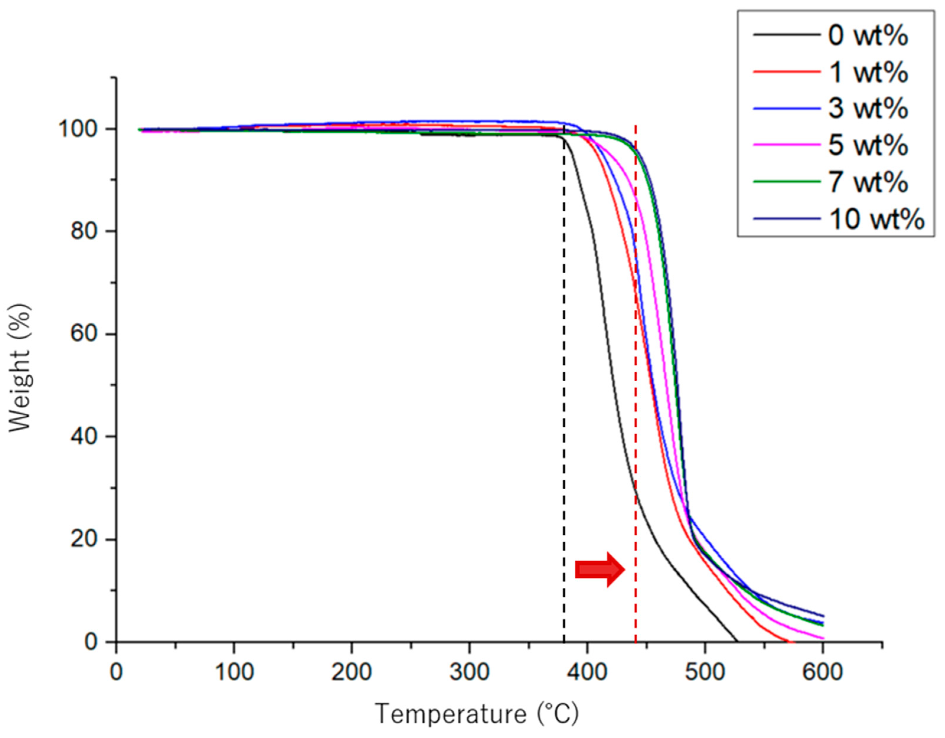
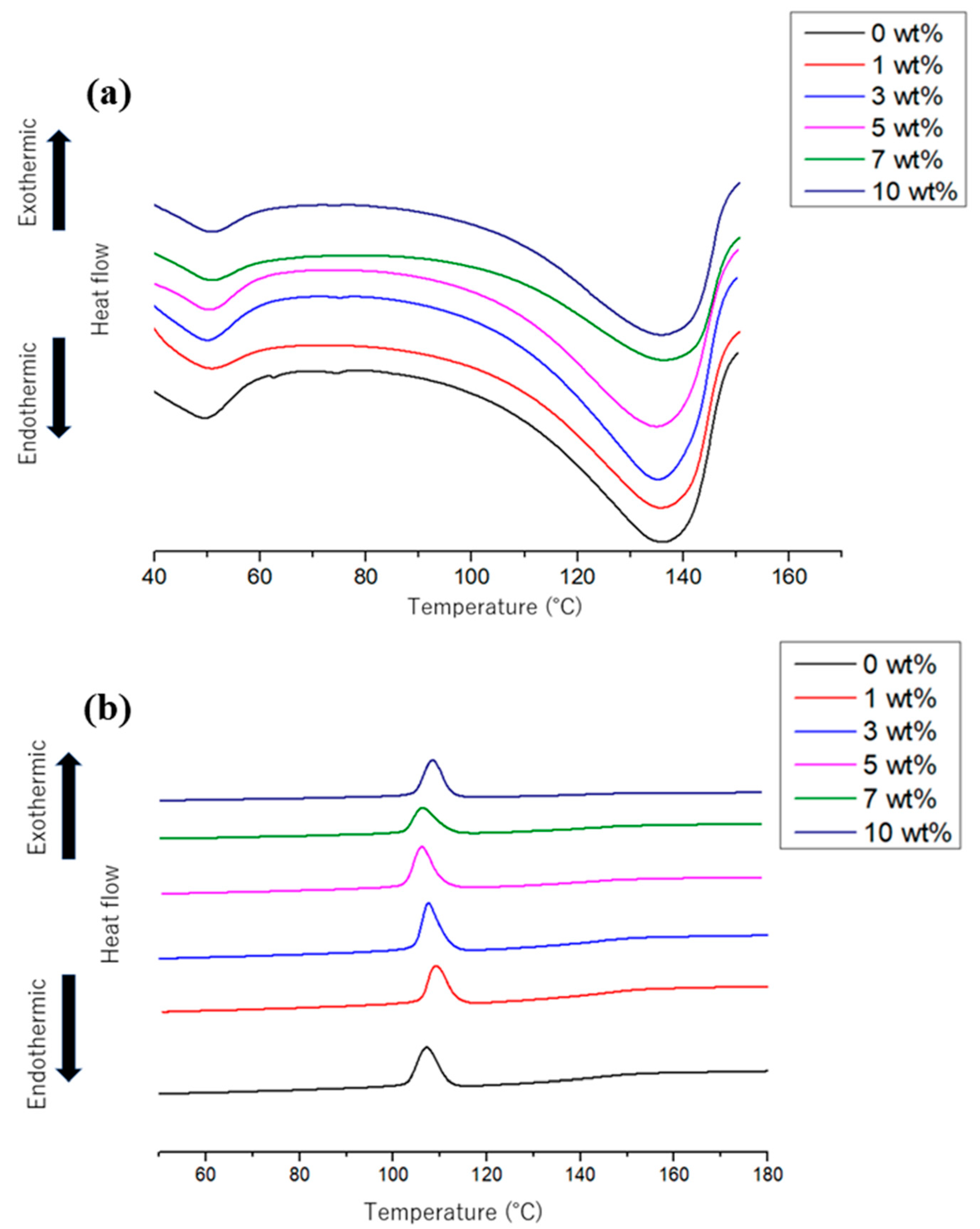
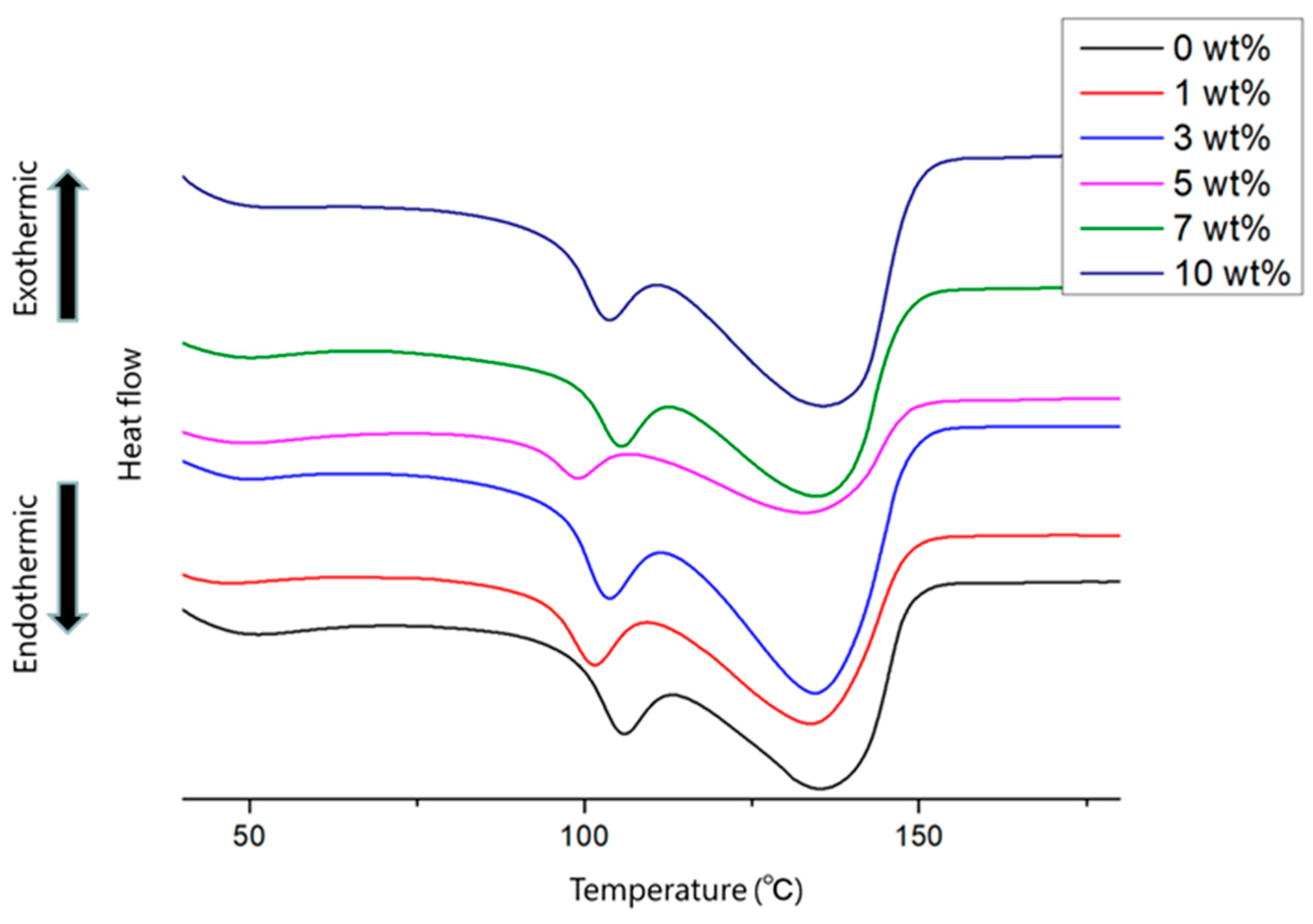
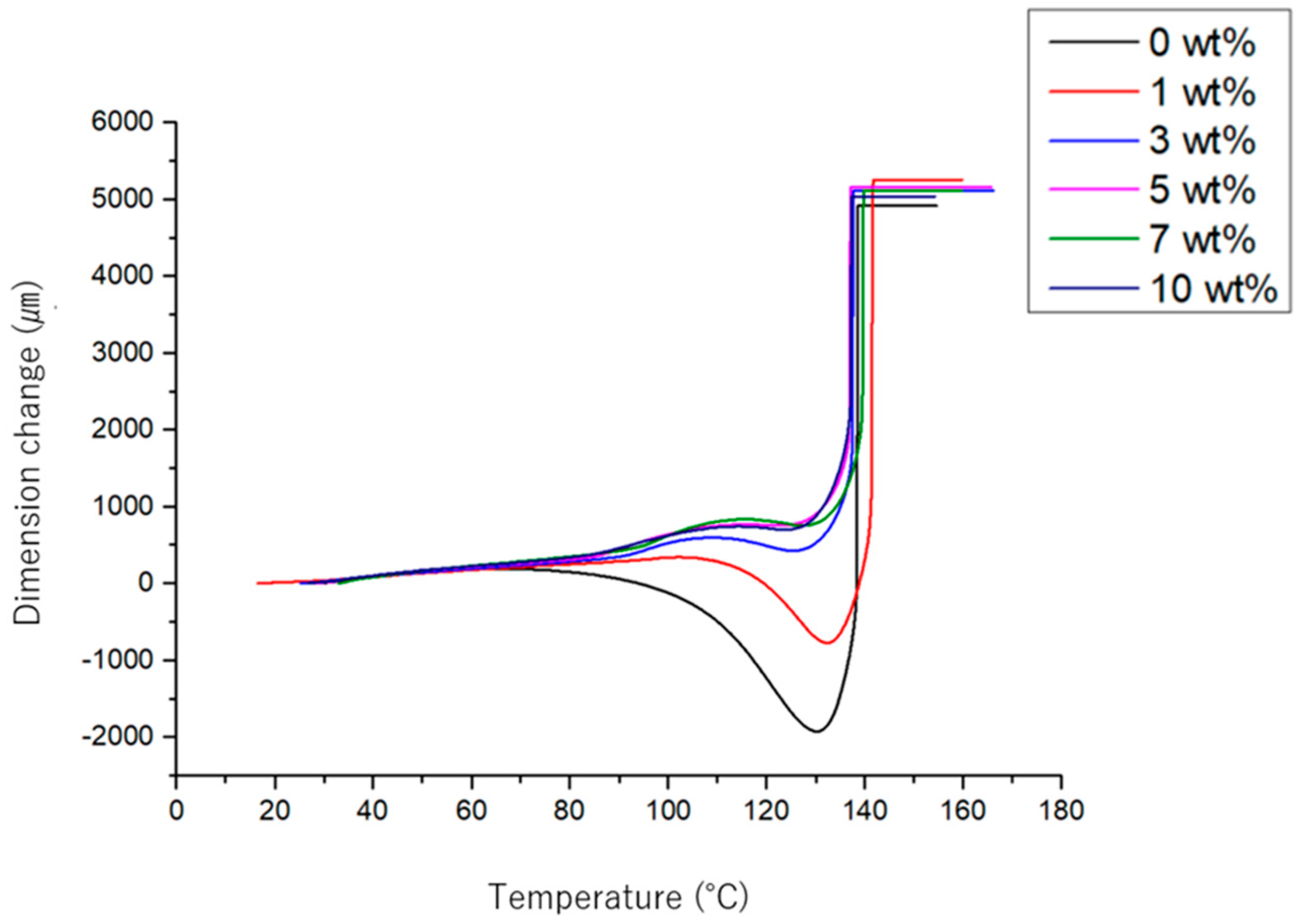
3.4. Thermal Analysis

The thermal characteristics of stabilized PVDF and PVDF/CB nanofibers were investigated using TGA and DSC. TGA showed that PVDF nanofibers exhibit no weight loss from ambient temperature to 390 °C (Figure 6) but weight loss between 390 and 450 °C and at ~530 °C (Figure 7). The first weight loss was attributed to depolymerization and degradation of the polymer structure [47,48]. The second weight loss was attributed to the instability of aromatic compounds generated during the first weight loss. Interestingly, PVDF/CB was more thermally stable than PVDF nanofiber. The weight loss of PVDF nanofibers began at 390 °C, whereas the weight loss of nanofibers containing 10% of CB began at 450 °C. That is, the addition of CB to PVDF increased thermal stability [47,49].
DSC thermographs of PVDF nanofibers and PVDF/CB nanofibers are shown in Figure 8a,b. During heating and cooling, a small endotherm was detected between 49 °C and 51 °C. This is typically observed for crystalline polymers and is attributed to the crystallization of amorphous material [50]. A prominent peak was observed at ~136 °C, corresponding to the melting point of PVDF/CB nanofiber. The result also displays the corresponding melting enthalpies and temperatures at which they melt at different temperatures. The melting enthalpy of PVDF nanofiber was increased by CB addition. A DSC thermograph of PVDF crystallization was taken between 107 and 109 °C [51]. Adding CB to PVDF decreased the enthalpy of crystallization, suggesting that CB retards the crystallization of PVDF. However, it was not determined whether the crystal phase that formed was piezoelectric.
DSC thermographs of thermally stabilized PVDF and PVDF/CB nanofibers are shown in Figure 9. The figure shows the presence of two peaks between 99 and 136 °C, which represent the melting points of the crystalline phases of PVDF. The PVDF/CB nanofiber crystalline phase caused the low-temperature peak, and the PVDF/CB nanofiber crystalline phase the high-temperature peak [52]. In contrast to the enthalpy of fusion preceding thermal stabilization, the enthalpy of fusion following thermal stabilization is greater. Thermal stabilization is presumed to have increased the crystalline component at the expense of the amorphous component.

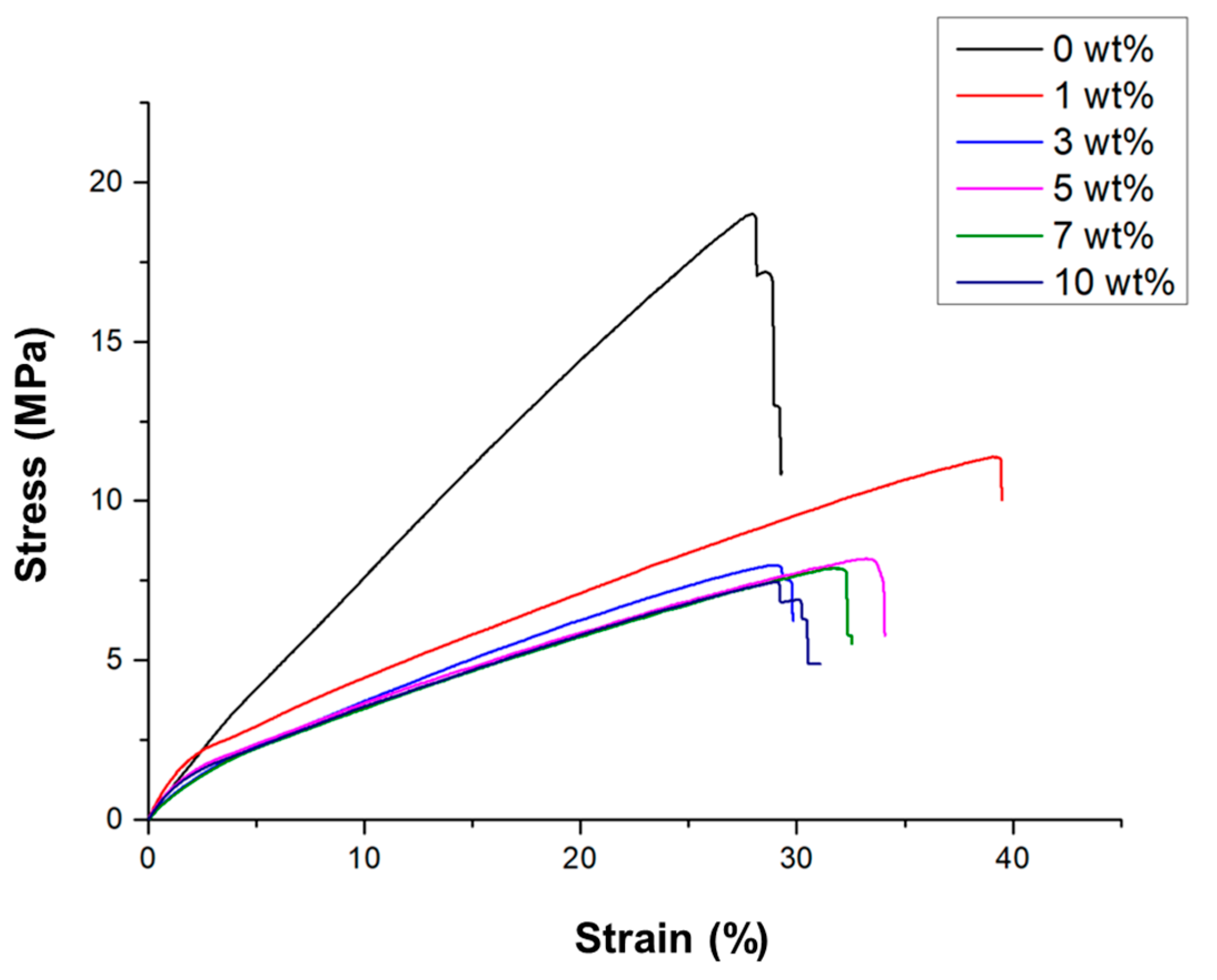
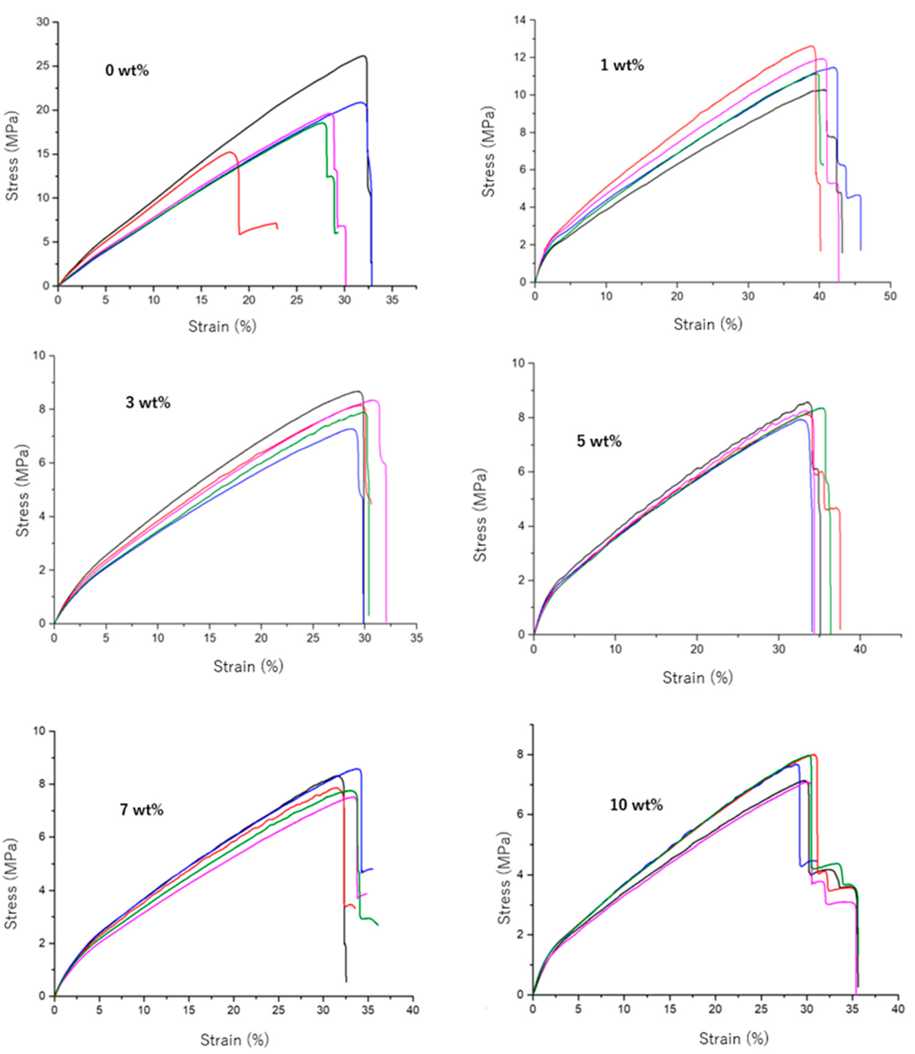
3.5. Mechanical Strength Analysis

Figure 10 shows thermally stabilized PVDF and PVDF/CB nanofiber stress–strain curves, and Figure 11 reveals corresponding stress–strain curves for different CB loadings. PVDF nanofibers failed at 20.07 ± 3.58 MPa, whereas PVDF/CB nanofibers at the different loadings failed at 1.49 ± 0.79, 8.06 ± 0.47, 8.25 ± 0.22, 8.00 ± 0.39, and 7.57 ± 0.40 MPa, respectively. The reduction in fracture stress was assumed to be due to CB aggregation, which causes stress concentrations and increases the likelihood of fractures. Because of the average fiber diameter, the CB quantity applied was 1 wt%. A previous study showed larger-diameter fibers have greater breaking strain [53]. The Young’s modulus of PVDF nanofibers was calculated by estimating the slope of a straight line drawn through the stress–strain diagram at a strain value of 2%. PVDF/CB nanofibers containing 1%, 3%, 5%, 7%, and 10% CB had Young’s moduli of 101.29 ± 15.94, 94.75 ± 10.40, 58.80 ± 4.63, 71.78 ± 3.54, 57.84 ± 3.67, and 68.75 ± 3.20 MPa. The addition of 1% of CB exhibited the greatest Young’s modulus.
The thermal shrinkage behaviors of thermally stabilized PVDF and PVDF/CB nanofibers were investigated by thermomechanical analysis; results are shown in Figure 12. At temperatures higher than 90 °C, PVDF nanofibers start to shrink, possibly caused by loss of the β phase to amorphization and relaxation [54,55,56,57]. Nanofiber contraction peaked at 131 °C; there was a thermal shrinkage of 2 mm, and it broke at a melting point of 140 °C. Young’s moduli explain why PVDF/CB nanofibers elongated at 112 °C. PVDF/CB nanofibers had a lower Young’s modulus and were more readily deformed than PVDF nanofibers. When CB was added at 1%, nanofibers shrank at 112 ℃, and this peaked at 134 ℃, resulting in a 900 μm contraction. Furthermore, nanofibers containing 3 wt% of CB exhibited shrinkage at 110 °C and peak shrinkage at 123 °C, which resulted in a thermal shrinkage of 17 μm. The 5, 7 and 10 wt% of CB loaded PVDF/CB nanofiber exhibited a small amount of thermal shrinkage at 115 °C. These observations show that CB at 5% loading is believed to have little effect on heat shrinkage. Crystal structure, crystal relaxation, and amorphization, and, thus, molecule mobility, were diminished due to the aggregation of CB within PVDF nanofibers.

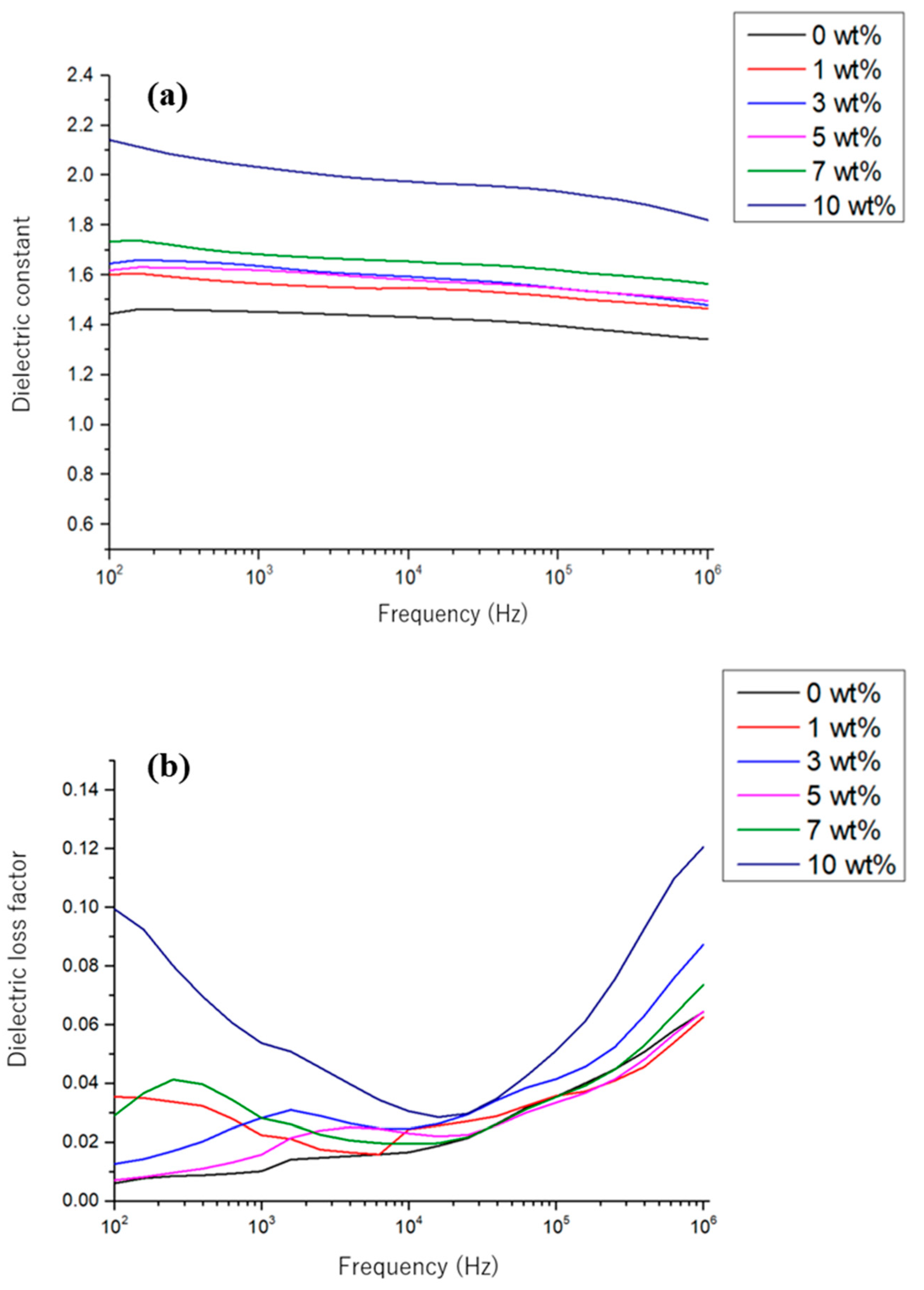
3.6. Dielectric Constant Measurements

The dielectric constants of PVDF/CB are presented in Figure 13a,b in the frequency range of 100–10−6 Hz at room temperature. According to the findings, the produced nanofiber’s dielectric constant at 1000 Hz is, correspondingly, 1.4, 1.5, 1.6, 1.7, and 2.0. The dielectric constant of the PVDF resin was 7.70. When the dielectric constants of PVDF resin and the nanofibers produced were compared, the dielectric constants of nanofibers were found to be obviously lower. The low-density nanofiber nonwoven fabric had a sponge-like structure and much air, which markedly affected measured dielectric constants. On the other hand, the inclusion of CB dose-dependently increased the dielectric constant due to its conductivity. Furthermore, polarization and electron mobility were enhanced by the presence of CB in nanofibers [58,59]. Relations between dielectric loss coefficients and frequency are plotted in Figure 13b. The energy lost when an alternating electric field is applied to an insulator (dielectric) is referred to as dielectric loss, and the dielectric losses of PVDF/CB at 1000 Hz were 0.010, 0.022, 0.028, 0.015, 0.028, and 0.053. At 1000 Hz, the dielectric loss of PVDF resin was 0.018 [58], and the dielectric loss of nanofibers increased dose dependently on adding CB to PVDF due to the increased electron mobility caused by adding CB.

4. Conclusions

In this study, PVDF/CB nanofibers were created using an electrospinning process, and the nanofibers were thermally stabilized to improve their properties. Nanofiber shapes were determined by FE-SEM and HR-TEM, and the results showed fiber diameters were increased by CB addition due to CB aggregation and as a result of thermal contraction during the thermal treatment. DSC study revealed that crystallization enthalpy was inversely proportional to the amount of CB added, which suggested that the ability of PVDF to crystallize was reduced by the presence of CB. Furthermore, crystal structures were verified by FT-IR, which also showed the β crystalline phase was present in all nanofibers produced. The γ crystalline phase, which is intermediate between the α and β crystalline phases, and the amorphous state were evident in nanofibers by P-XRD before thermal stabilization. Thermogravimetric measurements showed CB conferred remarkable thermal stability on PVDF/CB. Tensile experiments showed adding CB to thermally stabilized PVDF/CB nanofibers reduced Young’s moduli and fracture stress. Thermomechanical analysis was used to assess the thermal stability of PVDF/CB nanofibers. By adding CB, thermal shrinkage might be reduced. Furthermore, 5 CB wt% heat shrinkage was unaffected by the addition of the quantity above. Dielectric constant measurements demonstrated that PVDF/CB nanofibers had considerably lower dielectric constants than PVDF resin, and, in addition to lower Young’s moduli, PVDF/CB nanofibers were softer and more easily deformed than PVDF nanofibers. These properties and their excellent thermal stabilities indicate that PVDF/CB nanofibers are a promising raw material for flexible electronics and biomedical applications.

Author Contributions

Methodology, R.V. and R.K.; Software, G.M.; Formal analysis, T.K.; Investigation, G.M., R.K., S.C.K. and I.S.K.; Resources, T.K. and S.C.K.; Data curation, R.K.; Writing—original draft, R.V.; Supervision, G.M. and I.S.K.; Project administration, S.C.K. and I.S.K.; Funding acquisition, I.S.K. All authors have read and agreed to the published version of the manuscript.

Funding

This research was funded by Ministry of Education (2020R1I1A3052258).

Institutional Review Board Statement

Not applicable.

Informed Consent Statement

Not applicable.

Data Availability Statement

Data are contained within the article.

Acknowledgments

S.C. Kim greatly acknowledges the funding support.

Conflicts of Interest

The authors declare no conflict of interest.

References

  1. Fan, F.-R.; Tian, Z.-Q.; Wang, Z.L. Flexible triboelectric generator. Nano Energy 2012, 1, 328–334. [Google Scholar] [CrossRef]
  2. Kim, D.W.; Lee, J.H.; Kim, J.K.; Jeong, U. Material aspects of triboelectric energy generation and sensors. NPG Asia Mater. 2020, 12, 6. [Google Scholar] [CrossRef]
  3. Chen, X.; Han, X.; Shen, Q. PVDF-Based Ferroelectric Polymers in Modern Flexible Electronics. Adv. Electron. Mater. 2017, 3, 5. [Google Scholar] [CrossRef]
  4. Zhu, Y.; Wu, Y.; Wang, G.; Wang, Z.; Tan, Q.; Zhao, L.; Wu, D. A flexible capacitive pressure sensor based on an electrospun polyimide nanofiber membrane. Org. Electron. 2020, 84, 105759. [Google Scholar] [CrossRef]
  5. Yang, J.C.; Kim, J.O.; Oh, J.; Kwon, S.Y.; Sim, J.Y.; Kim, D.; Choi, H.B.; Park, S. Microstructured Porous Pyramid-Based Ultrahigh Sensitive Pressure Sensor Insensitive to Strain and Temperature. ACS Appl. Mater. Interfaces 2019, 11, 19472–19480. [Google Scholar] [CrossRef]
  6. Alam, M.; Lee, S.; Kim, M.; Han, K.S.; Cao, V.A.; Nah, J. Ultra-flexible nanofiber-based multifunctional motion sensor. Nano Energy 2020, 72, 104672. [Google Scholar] [CrossRef]
  7. Li, R.; Zhou, Q.; Bi, Y.; Cao, S.; Xia, X.; Yang, A.; Li, S.; Xiao, X. Research progress of flexible capacitive pressure sensor for sensitivity enhancement approaches. Sens. Actuators A Phys. 2021, 321, 112425. [Google Scholar] [CrossRef]
  8. Zheng, Y.; Li, Y.; Li, Z.; Wang, Y.; Dai, K.; Zheng, G.; Liu, C.; Shen, C. The effect of filler dimensionality on the electromechanical performance of polydimethylsiloxane based conductive nanocomposites for flexible strain sensors. Compos. Sci. Technol. 2017, 139, 64–73. [Google Scholar] [CrossRef]
  9. Yang, X.; Wang, Y.; Qing, X. A flexible capacitive sensor based on the electrospun PVDF nanofiber membrane with carbon nanotubes. Sens. Actuators A Phys. 2019, 299, 111579. [Google Scholar] [CrossRef]
  10. Mishra, S.; Kumaran, K.T.; Sivakumaran, R.; Pandian, S.P.; Kundu, S. Synthesis of PVDF/CNT and their functionalized composites for studying their electrical properties to analyze their applicability in actuation & sensing. Colloids Surfaces A Physicochem. Eng. Asp. 2016, 509, 684–696. [Google Scholar]
  11. Yuan, R.; Dong, Y.; Hou, R.; Shang, L.; Zhang, J.; Zhang, S.; Chen, X.; Song, H. Structural transformation of porous and disordered carbon during ball-milling. Chem. Eng. J. 2023, 454, 140418. [Google Scholar] [CrossRef]
  12. Zhang, F.; Si, Y.; Yu, J.; Ding, B. Electrospun porous engineered nanofiber materials: A versatile medium for energy and environmental applications. Chem. Eng. J. 2023, 456, 140989. [Google Scholar] [CrossRef]
  13. Qi, Y.; Wang, C.; Wang, Q.; Zhou, F.; Li, T.; Wang, B.; Su, W.; Shang, D.; Wu, S. A simple, quick, and cost-effective strategy to fabricate polycaprolactone/silk fibroin nanofiber yarns for biotextile-based tissue scaffold application. Eur. Polym. J. 2023, 186, 111863. [Google Scholar] [CrossRef]
  14. Chen, Y.; Chen, Y.; Mao, M.; Wu, Y.; Yang, F.; Gong, X.; Zhao, L.; Cao, F.; Song, P.; Gao, F.; et al. Self-Adhesive Polydimethylsiloxane Foam Materials Decorated with MXene/Cellulose Nanofiber Interconnected Network for Versatile Functionalities. Adv. Funct. Mater. 2023, 33, 2304927. [Google Scholar] [CrossRef]
  15. Arjmandi, S.K.; Khademzadeh Yeganeh, J.; Zare, Y.; Rhee, K.Y. Development of Kovacs model for electrical conductivity of carbon nanofiber–polymer systems. Sci. Rep. 2023, 13, 7. [Google Scholar] [CrossRef] [PubMed]
  16. Nakata, K.; Fujii, K.; Ohkoshi, Y.; Gotoh, Y.; Nagura, M.; Numata, M.; Kamiyama, M. Poly(ethylene terephthalate) nanofibers made by sea-island-type conjugated melt spinning and laser-heated flow drawing. Macromol. Rapid Commun. 2007, 28, 792–795. [Google Scholar] [CrossRef]
  17. Jiang, H.; Yao, M.; Chen, J.; Zhang, M.; Hong, W. Advances in biomass-based nanofibers prepared by electrospinning for energy storage devices. Fuel 2023, 355, 129534. [Google Scholar] [CrossRef]
  18. Deitzel, J.M.; Kleinmeyer, J.; Harris, D.; Beck Tan, N.C. The effect of processing variables on the morphology of electrospun. Polymer 2001, 42, 261–272. [Google Scholar] [CrossRef]
  19. Kenry; Lim, C.T. Nanofiber technology: Current status and emerging developments. Prog. Polym. Sci. 2017, 70, 1–17. [Google Scholar] [CrossRef]
  20. Kim, I.S. Recent trends in the commercialization of nanofibers. J. Funct. Pap. Res. Soc. 2021, 59, 51–59. [Google Scholar]
  21. Kianfar, P.; Bongiovanni, R.; Ameduri, B.; Vitale, A. Electrospinning of Fluorinated Polymers: Current State of the Art on Processes and Applications. Polym. Rev. 2023, 63, 127–199. [Google Scholar] [CrossRef]
  22. Abdulhamid, M.A.; Muzamil, K. Recent progress on electrospun nanofibrous polymer membranes for water and air purification: A review. Chemosphere 2022, 310, 136886. [Google Scholar] [CrossRef] [PubMed]
  23. Abdul Hameed, M.M.; Padusha Mohamed Khan, S.A.; Thamer, B.M.; Rajkumar, N.; El-Hamshary, H.; El-Newehy, M. Electrospun nanofibers for drug delivery applications: Methods and mechanism. Polym. Adv. Technol. 2022, 34, 6–23. [Google Scholar] [CrossRef]
  24. Patel, P.R.; Naga Gundloori, R.V. A review on electrospun nanofibers for multiple biomedical applications. Polym. Adv. Technol. 2022, 34, 44–63. [Google Scholar] [CrossRef]
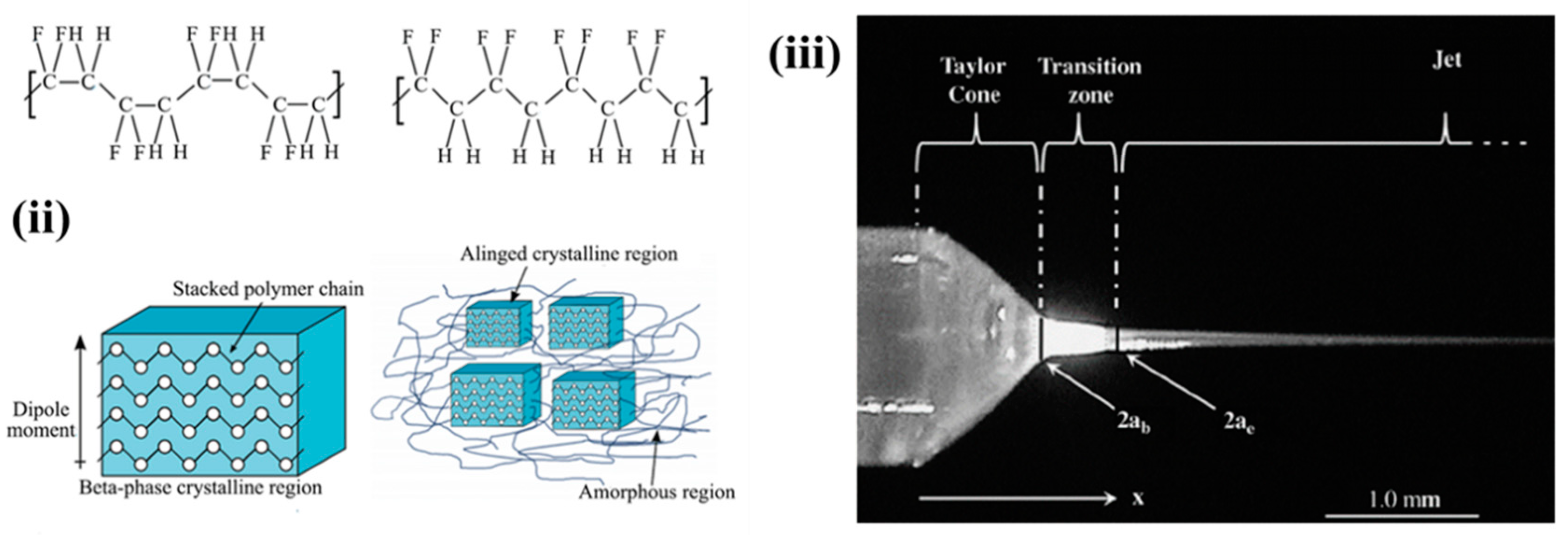
  25. Cruz-Mazo, F.; Wiedorn, M.O.; Herrada, M.A.; Bajt, S.; Chapman, H.N.; Gañán-Calvo, A.M. Aerodynamically stabilized Taylor cone jets. Phys. Rev. E 2019, 100, 31101. [Google Scholar] [CrossRef] [PubMed]
  26. Reneker, D.H.; Yarin, A.L.; Fong, H.; Koombhongse, S. Bending instability of electrically charged liquid jets of polymer solutions in electrospinning. J. Appl. Phys. 2000, 87, 4531. [Google Scholar] [CrossRef]
  27. Jiang, S.; Chen, Y.; Duan, G.; Mei, C.; Greiner, A.; Agarwal, S. Electrospun nanofiber reinforced composites: A review. Polym. Chem. 2018, 9, 2685–2720. [Google Scholar] [CrossRef]
  28. Shin, Y.M.; Hohman, M.M.; Brenner, M.P.; Rutledge, G.C. Electrospinning: A whipping fluid jet generates submicron polymer fibers. Appl. Phys. Lett. 2001, 78, 1149. [Google Scholar] [CrossRef]
  29. Phan, D.-N.; Lee, H.; Huang, B.; Mukai, Y.; Kim, I.-S. Fabrication of electrospun chitosan/cellulose nanofibers having adsorption property with enhanced mechanical property. Cellulose 2019, 26, 1781–1793. [Google Scholar] [CrossRef]
  30. Leung, W.W.-F.; Hung, C.-H.; Yuen, P.-T. Effect of face velocity, nanofiber packing density and thickness on filtration performance of filters with nanofibers coated on a substrate. Sep. Purif. Technol. 2010, 71, 30–37. [Google Scholar] [CrossRef]
  31. Ullah, S.; Ullah, A.; Lee, J.; Jeong, Y.; Hashmi, M.; Zhu, C.; Joo, K., II; Cha, H.J.; Kim, I.S. Reusability Comparison of Melt-Blown vs. Nanofiber Face Mask Filters for Use in the Coronavirus Pandemic. ACS Appl. Nano Mater. 2020, 3, 7231–7241. [Google Scholar] [CrossRef] [PubMed]
  32. Bjorge, D.; Daels, N.; De Vrieze, S.; Dejans, P.; Van Camp, T.; Audenaert, W.; Hogie, J.; Westbroek, P.; De Clerck, K.; Van Hulle, S.W.H. Performance assessment of electrospun nanofibers for filter applications. Desalination 2009, 249, 942–948. [Google Scholar] [CrossRef]
  33. Kim, B.H.; Yang, K.S.; Woo, H.G. Thin, bendable electrodes consisting of porous carbon nanofibers via the electrospinning of polyacrylonitrile containing tetraethoxy orthosilicate for supercapacitor. Electrochem. Commun. 2011, 13, 1042–1046. [Google Scholar] [CrossRef]
  34. Kim, C.; Yang, K.S.; Kojima, M.; Yoshida, K.; Kim, Y.J.; Kim, Y.A.; Endo, M. Fabrication of Electrospinning-Derived Carbon Nanofiber Webs for the Anode Material of Lithium-Ion Secondary Batteries. Adv. Funct. Mater. 2006, 16, 2393–2397. [Google Scholar] [CrossRef]
  35. Kim, G.H.; Kim, W.D. Highly porous 3D nanofiber scaffold using an electrospinning technique. J. Biomed. Mater. Res. Part B Appl. Biomater. 2007, 81, 104–110. [Google Scholar] [CrossRef] [PubMed]
  36. Yoshimoto, H.; Shin, Y.M.; Terai, H.; Vacanti, J.P. A biodegradable nanofiber scaffold by electrospinning and its potential for bone tissue engineering. Biomaterials 2003, 24, 2077–2082. [Google Scholar] [CrossRef]
  37. Ullah, A.; Ullah, S.; Khan, M.Q.; Hashmi, M.; Nam, P.D.; Kato, Y.; Tamada, Y.; Kim, I.S. Manuka honey incorporated cellulose acetate nanofibrous mats: Fabrication and in vitro evaluation as a potential wound dressing. Int. J. Biol. Macromol. 2020, 155, 479–489. [Google Scholar] [CrossRef]
  38. Yıldız, A.; Kara, A.A.; Acartürk, F. Peptide-protein based nanofibers in pharmaceutical and biomedical applications. Int. J. Biol. Macromol. 2020, 148, 1084–1097. [Google Scholar] [CrossRef]
  39. Neidhöfer, M.; Beaume, F.; Ibos, L.; Bernès, A.; Lacabanne, C. Structural evolution of PVDF during storage or annealing. Polymer 2004, 45, 1679–1688. [Google Scholar] [CrossRef]
  40. Indolia, A.P.; Gaur, M.S. Investigation of structural and thermal characteristics of PVDF/ZnO nanocomposites. J. Therm. Anal. Calorim. 2013, 113, 821–830. [Google Scholar] [CrossRef]
  41. Merlini, C.; Barra, G.M.O.; Araujo, T.M.; Pegoretti, A. Electrically pressure sensitive poly(vinylidene fluoride)/polypyrrole electrospun mats. RSC Adv. 2014, 4, 15749–15758. [Google Scholar] [CrossRef]
  42. Cai, X.; Lei, T.; Sun, D.; Lin, L. A critical analysis of the α, β and γ phases in poly(vinylidene fluoride) using FTIR. RSC Adv. 2017, 7, 15382–15389. [Google Scholar] [CrossRef]
  43. Salimi, A.; Yousefi, A.A. Analysis Method: FTIR studies of β-phase crystal formation in stretched PVDF films. Polym. Test. 2003, 22, 699–704. [Google Scholar] [CrossRef]
  44. Wu, C.M.; Chou, M.H. Polymorphism, piezoelectricity and sound absorption of electrospun PVDF membranes with and without carbon nanotubes. Compos. Sci. Technol. 2016, 127, 127–133. [Google Scholar] [CrossRef]
  45. Sengupta, D.; Kottapalli AG, P.; Chen, S.H.; Miao, J.M.; Kwok, C.Y.; Triantafyllou, M.S.; Warkiani, W.E.; Asadnia, M. Characterization of single polyvinylidene fluoride (PVDF) nanofiber for flow sensing applications. AIP Adv. 2017, 7, 105205. [Google Scholar] [CrossRef]
  46. Tiwari, V.; Srivastava, G. Effect of thermal processing conditions on the structure and dielectric properties of PVDF films. J. Polym. Res. 2014, 21, 587. [Google Scholar] [CrossRef]
  47. Gregorio, R.; Cestari, M. Effect of crystallization temperature on the crystalline phase content and morphology of poly(vinylidene fluoride). J. Polym. Sci. Part B Polym. Phys. 1994, 32, 859–870. [Google Scholar] [CrossRef]
  48. Jaleh, B.; Jabbari, A. Evaluation of reduced graphene oxide/ZnO effect on properties of PVDF nanocomposite films. Appl. Surf. Sci. 2014, 320, 339–347. [Google Scholar] [CrossRef]
  49. Ahn, Y.; Lim, J.Y.; Hong, S.M.; Lee, J.; Ha, J.; Choi, H.J.; Seo, Y. Enhanced piezoelectric properties of electrospun poly(vinylidene fluoride)/multiwalled carbon nanotube composites due to high β-phase formation in poly(vinylidene fluoride). J. Phys. Chem. C 2013, 117, 11791–11799. [Google Scholar] [CrossRef]
  50. Zucolotto, V.; Avlyanov, J.; Gregorio, R.; Mattoso, L.H.C. Melt processing of composites of PVDF and carbon black modified with conducting polymers. J. Appl. Polym. Sci. 2004, 94, 553–557. [Google Scholar] [CrossRef]
  51. João, J.S.; Ribeiro, A.A.; Cardoso, C.X. Preparation and characterization of PVDF/CaCO3 composites. Mater. Sci. Eng. B 2007, 136, 123–128. [Google Scholar]
  52. Brito Guaricela, J.L.; Ahrens, C.H.; de Oliveira Barra, G.M.; Merlini, C. Evaluation of poly(vinylidene fluoride)/carbon black composites, manufactured by selective laser sintering. Polym. Compos. 2021, 42, 2457–2468. [Google Scholar] [CrossRef]
  53. Choi, S.S.; Lee, Y.S.; Joo, C.W.; Lee, S.G.; Park, J.K.; Han, K.S. Electrospun PVDF nanofiber web as polymer electrolyte or separator. Electrochim. Acta 2004, 50, 339–343. [Google Scholar] [CrossRef]
  54. Chang, W.Y.; Fang, T.H.; Liu, S.Y.; Lin, Y.C. Phase transformation and thermomechanical characteristics of stretched polyvinylidene fluoride. Mater. Sci. Eng. A 2008, 480, 477–482. [Google Scholar] [CrossRef]
  55. Hou, C.; Pang, Z.; Xie, S.; Hing Wong, N.; Sunarso, J.; Peng, Y. Enhanced permeability and stability of PVDF hollow fiber membrane in DCMD via heat-stretching treatment. Sep. Purif. Technol. 2022, 304, 122325. [Google Scholar] [CrossRef]
  56. Park, S.; Son, C.W.; Lee, S.; Kim, D.Y.; Park, C.; Eom, K.S.; Fuller, T.F.; Joh, H.-I.; Jo, S.M. Multicore-shell nanofiber architecture of polyimide/polyvinylidene fluoride blend for thermal and long-term stability of lithium ion battery separator. Sci. Rep. 2016, 6, 36977. [Google Scholar] [CrossRef]
  57. Sencadas, V.; Lanceros-Méndez, S.; Mano, J.F. Characterization of poled and non-poled β-PVDF films using thermal analysis techniques. Thermochim. Acta 2004, 424, 201–207. [Google Scholar] [CrossRef]
  58. Lin, B.; Li, Z.T.; Yang, Y.; Li, Y.; Lin, J.C.; Zheng, X.M.; He, F.-A.; Lam, K.-H. Enhanced dielectric permittivity in surface-modified graphene/PVDF composites prepared by an electrospinning-hot pressing method. Compos. Sci. Technol. 2019, 172, 58–65. [Google Scholar] [CrossRef]
  59. Chen, S.; Chen, S.; Qiao, R.; Xu, H.; Liu, Z.; Luo, H.; Zhang, D. Enhanced dielectric constant of PVDF-based nanocomposites with one-dimensional core-shell polypyrrole/sepiolite nanofibers. Compos. Part A Appl. Sci. Manuf. 2021, 145, 106384. [Google Scholar] [CrossRef]
Figure 1. The schematic representation of the preparation of PVDF/CB nanofiber (i), the molecular structure and the crystalline alignment of PVDF (ii), and the electrospinning process for the preparation of nanofiber (iii).
Coatings 14 00035 g001aCoatings 14 00035 g001b
Figure 2. FT-IR spectra of PVDF/CB nanofiber (a) and stabilized PVDF/CB nanofiber (b).
Coatings 14 00035 g002
Figure 3. XRD patterns of PVDF/CB nanofiber (a) and PVDF/CB nanofiber after stabilization (b).
Coatings 14 00035 g003
Figure 4. The FE-SEM images of the stabilized PVDF/CB nanofiber at various loading percentages.
Coatings 14 00035 g004
Figure 5. HR-TEM images of stabilized PVDF/CB nanofiber at various percentages; circle: loaded CB particle on the surface of PVDF nanofiber.
Coatings 14 00035 g005
Figure 6. The electrospinning machine setup (a), the PVDF/CB nanofiber images before (b) and after (c) stabilization, flexibility (d), and the AFM results of the nanofibers (eh).
Coatings 14 00035 g006
Figure 7. TGA curves of stabilized PVDF/CB nanofiber.
Coatings 14 00035 g007
Figure 8. Heating (a) and cooling (b) DSC thermograms of PVDF/CB nanofiber.
Coatings 14 00035 g008
Figure 9. Heating DSC thermograms of stabilized PVDF/CB nanofiber.
Coatings 14 00035 g009
Figure 10. Stress–strain curves of PVDF/CB nanofibers at various concentrations.
Coatings 14 00035 g010
Figure 11. The stress–strain curves of PVDF/CB nanofibers at various concentrations and different loadings (lower to higher; black < lavender < pink < green < blue).
Coatings 14 00035 g011
Figure 12. TMA curve of PVDF/CB nanofibers at various concentrations.
Coatings 14 00035 g012
Figure 13. The dielectric constants (a) and dielectric loss of PVDF/CB nanofibers (b).
Coatings 14 00035 g013
Disclaimer/Publisher’s Note: The statements, opinions and data contained in all publications are solely those of the individual author(s) and contributor(s) and not of MDPI and/or the editor(s). MDPI and/or the editor(s) disclaim responsibility for any injury to people or property resulting from any ideas, methods, instructions or products referred to in the content.

