
Influence of the Gas Flow Rate on the Crack Formation of AlCoCrNi High-Entropy Metallic Film Fabricated Using Magnetron Sputtering

Abstract
:
1. Introduction
2. Materials and Methods
2.1. Sample Preparation
2.2. Microstructure Characterization
2.3. Mechanical Properties
3. Results and Discussion
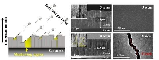
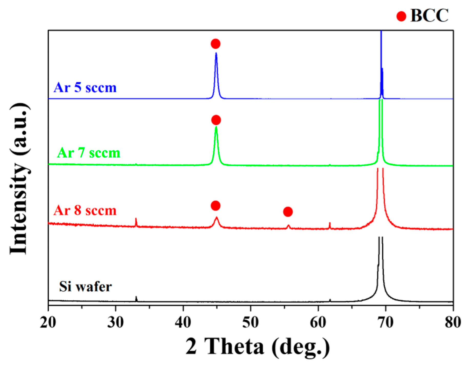
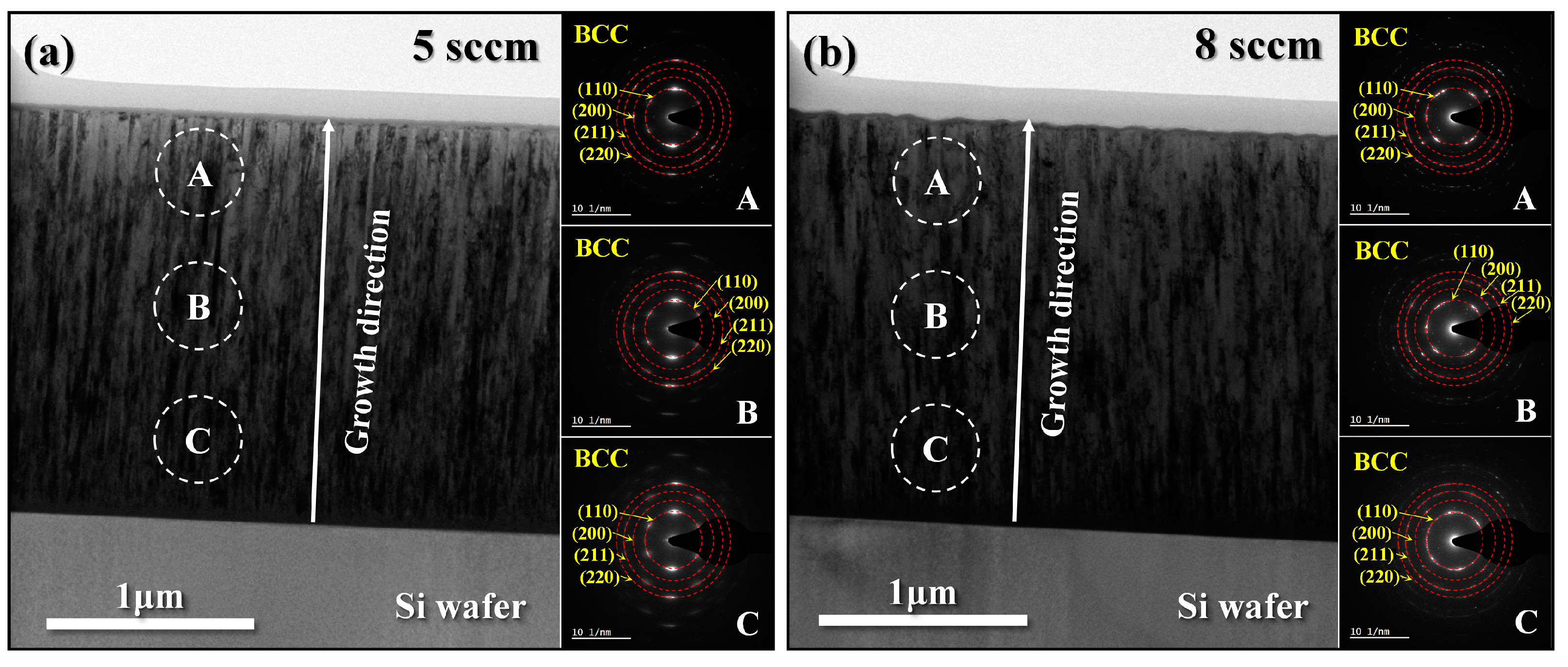
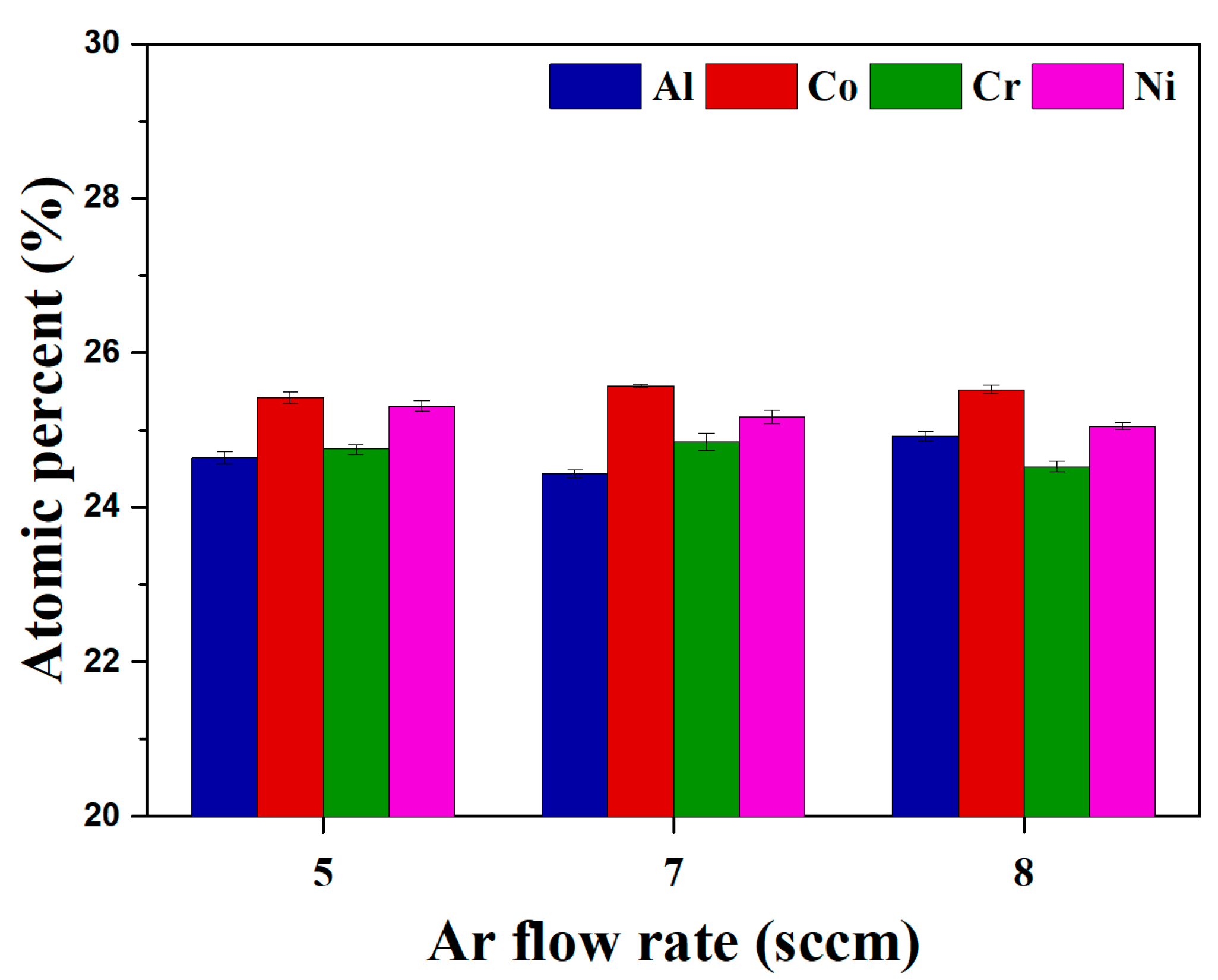
3.1. Phase Analysis and Microstructure Characterization of Thin Films
3.2. Nanoindentation Test
4. Conclusions
Author Contributions
Funding
Institutional Review Board Statement
Informed Consent Statement
Data Availability Statement
Conflicts of Interest
References
- Cantor, B.; Chang, I.T.H.; Knight, P.; Vincent, A.J.B. Microstructural Development in Equiatomic Multicomponent Alloys. Mater. Sci. Eng. A 2004, 375, 213–218. [Google Scholar] [CrossRef]
- Yeh, J.-W. Recent Progress in High Entropy Alloys. Ann. Chim. Sci. Mater. 2006, 31, 633–648. [Google Scholar]
- Yan, X.H.; Li, J.S.; Zhang, W.R.; Zhang, Y. A Brief Review of High-Entropy Films. Mater. Chem. Phys. 2018, 210, 12–19. [Google Scholar] [CrossRef]
- Zhang, Y.; Zhou, Y.J.; Lin, J.P.; Chen, G.L.; Liaw, P.K. Solid-solution Phase Formation Rules for Multi-component Alloys. Adv. Eng. Mater. 2008, 10, 534–538. [Google Scholar] [CrossRef]
- George, E.P.; Raabe, D.; Ritchie, R.O. High-Entropy Alloys. Nat. Rev. Mater. 2019, 4, 515–534. [Google Scholar] [CrossRef]
- Park, H.J.; Na, Y.S.; Hong, S.H.; Kim, J.T.; Kim, Y.S.; Lim, K.R.; Park, J.M.; Kim, K.B. Phase Evolution, Microstructure and Mechanical Properties of Equi-Atomic Substituted TiZrHfNiCu and TiZrHfNiCuM (M = Co, Nb) High-Entropy Alloys. Met. Mater. Int. 2016, 22, 551–556. [Google Scholar] [CrossRef]
- Jumaev, E.; Hong, S.H.; Kim, J.T.; Park, H.J.; Kim, Y.S.; Mun, S.C.; Park, J.-Y.; Song, G.; Lee, J.K.; Min, B.H.; et al. Chemical Evolution-Induced Strengthening on AlCoCrNi Dual-Phase High-Entropy Alloy with High Specific Strength. J. Alloys Compd. 2019, 777, 828–834. [Google Scholar] [CrossRef]
- Park, H.J.; Kim, Y.S.; Mun, S.C.; Hong, S.H.; Wang, W.-M.; Kim, K.B. Designing of Fe-Containing (Ti33Zr33Hf33)-(Ni50Cu50) High Entropy Alloys Developed by Equiatomic Substitution: Phase Evolution and Mechanical Properties. J. Mater. Res. Technol. 2020, 9, 7732–7739. [Google Scholar] [CrossRef]
- Pogrebnjak, A.D.; Bagdasaryan, A.A.; Yakushchenko, I.V.; Beresnev, V.M. The Structure and Properties of High-Entropy Alloys and Nitride Coatings Based on Them The Structure and Properties of High-Entropy Alloys and Nitride Coatings Based on Them. Russ. Chem. Rev. 2014, 83, 1027. [Google Scholar] [CrossRef]
- Kim, H.; Nam, S.; Roh, A.; Son, M.; Ham, M.-H.; Kim, J.-H.; Choi, H. Mechanical and Electrical Properties of NbMoTaW Refractory High-Entropy Alloy Thin Films. Int. J. Refract. Met. Hard Mater. 2019, 80, 286–291. [Google Scholar] [CrossRef]
- Gorr, B.; Müller, F.; Azim, M.; Christ, H.-J.; Müller, T.; Chen, H.; Kauffmann, A.; Heilmaier, M. High-Temperature Oxidation Behavior of Refractory High-Entropy Alloys: Effect of Alloy Composition. Oxid. Met. 2017, 88, 339–349. [Google Scholar] [CrossRef]
- Zhou, Y.J.; Zhang, Y.; Wang, Y.L.; Chen, G.L. Solid Solution Alloys of AlCoCrFeNiTix with Excellent Room-Temperature Mechanical Properties. Appl. Phys. Lett. 2007, 90, 181904. [Google Scholar] [CrossRef]
- Huang, Y.-S.; Chen, L.; Lui, H.-W.; Cai, M.-H.; Yeh, J.-W. Microstructure, Hardness, Resistivity and Thermal Stability of Sputtered Oxide Films of AlCoCrCu0.5NiFe High-Entropy Alloy. Mater. Sci. Eng. A 2007, 457, 77–83. [Google Scholar] [CrossRef]
- Wu, J.-M.; Lin, S.-J.; Yeh, J.-W.; Chen, S.-K.; Huang, Y.-S.; Chen, H.-C. Adhesive Wear Behavior of AlxCoCrCuFeNi High-Entropy Alloys as a Function of Aluminum Content. Wear 2006, 261, 513–519. [Google Scholar] [CrossRef]
- Tsai, D.-C.; Chang, Z.-C.; Kuo, B.-H.; Tsao, C.-T.; Chen, E.-C.; Shieu, F.-S. Influence of Discharge Power on the Structural, Electro-Optical, and Mechanical Properties of (TiZrHf) N Coatings. J. Alloys Compd. 2015, 622, 446–457. [Google Scholar] [CrossRef]
- Jin, H.; Seok, Y.; Hoon, Y.; Hwan, S.; Sik, K.; Koon, Y.; Buem, K. Design of Nano-Scale Multilayered Nitride Hard Coatings Deposited by Arc Ion Plating Process: Microstructural and Mechanical Characterization. J. Mater. Res. Technol. 2021, 15, 572–581. [Google Scholar] [CrossRef]
- Pierson, H.O. Handbook of Refractory Carbides & Nitrides: Properties, Characteristics, Processing and Applications; William Andrew: Norwich, NY, USA, 1996; ISBN 081551770X. [Google Scholar]
- Cheng, J.B.; Liang, X.B.; Wang, Z.H.; Xu, B.S. Formation and Mechanical Properties of CoNiCuFeCr High-Entropy Alloys Coatings Prepared by Plasma Transferred Arc Cladding Process. Plasma Chem. Plasma Process. 2013, 33, 979–992. [Google Scholar] [CrossRef]
- Zhang, C.; Chen, G.J.; Dai, P.Q. Evolution of the Microstructure and Properties of Laser-Clad FeCrNiCoBx High-Entropy Alloy Coatings. Mater. Sci. Technol. 2016, 32, 1666–1672. [Google Scholar] [CrossRef]
- Hsieh, M.-H.; Tsai, M.-H.; Shen, W.-J.; Yeh, J.-W. Structure and Properties of Two Al–Cr–Nb–Si–Ti High-Entropy Nitride Coatings. Surf. Coat. Technol. 2013, 221, 118–123. [Google Scholar] [CrossRef]
- Kim, Y.S.; Park, H.J.; Mun, S.C.; Jumaev, E.; Hong, S.H.; Song, G.; Kim, J.T.; Park, Y.K.; Kim, K.S.; Jeong, S.I.; et al. Investigation of Structure and Mechanical Properties of TiZrHfNiCuCo High Entropy Alloy Thin Films Synthesized by Magnetron Sputtering. J. Alloys Compd. 2019, 797, 834–841. [Google Scholar] [CrossRef]
- Kim, Y.S.; Park, H.J.; Lim, K.S.; Hong, S.H.; Kim, K.B. Structural and Mechanical Properties of AlCoCrNi High Entropy Nitride Films: Influence of Process Pressure. Coatings 2019, 10, 10. [Google Scholar] [CrossRef]
- Khan, N.A.; Akhavan, B.; Zhou, C.; Zhou, H.; Chang, L.; Wang, Y.; Liu, Y.; Bilek, M.M.; Liu, Z. High Entropy Nitride (HEN) Thin Films of AlCoCrCu0.5FeNi Deposited by Reactive Magnetron Sputtering. Surf. Coat. Technol. 2020, 402, 126327. [Google Scholar] [CrossRef]
- Khan, N.A.; Akhavan, B.; Zhou, C.; Zhou, H.; Chang, L.; Wang, Y.; Liu, Y.; Fu, L.; Bilek, M.M.; Liu, Z. RF Magnetron Sputtered AlCoCrCu0.5FeNi High Entropy Alloy (HEA) Thin Films with Tuned Microstructure and Chemical Composition. J. Alloys Compd. 2020, 836, 155348. [Google Scholar] [CrossRef]
- Khan, N.A.; Akhavan, B.; Zhou, H.; Chang, L.; Wang, Y.; Sun, L.; Bilek, M.M.; Liu, Z. High Entropy Alloy Thin Films of AlCoCrCu0.5FeNi with Controlled Microstructure. Appl. Surf. Sci. 2019, 495, 143560. [Google Scholar] [CrossRef]
- Liao, W.; Lan, S.; Gao, L.; Zhang, H.; Xu, S.; Song, J.; Wang, X.; Lu, Y. Nanocrystalline High-Entropy Alloy (CoCrFeNiAl0.3) Thin-Film Coating by Magnetron Sputtering. Thin Solid Film. 2017, 638, 383–388. [Google Scholar] [CrossRef]
- Karunasiri, R.P.U.; Bruinsma, R.; Rudnick, J. Thin-Film Growth and the Shadow Instability. Phys. Rev. Lett. 1989, 62, 788–791. [Google Scholar] [CrossRef] [PubMed]
- Salvalaglio, M.; Backofen, R.; Voigt, A. Thin-Film Growth Dynamics with Shadowing Effects by a Phase-Field Approach. Phys. Rev. B 2016, 94, 235432. [Google Scholar] [CrossRef]
- Hu, M.; Cao, Q.P.; Wang, X.D.; Zhang, D.X.; Jiang, J.-Z. Tuning Nanostructure and Mechanical Property of Fe–Co–Ni–Cr–Mn High-Entropy Alloy Thin Films by Substrate Temperature. Mater. Today Nano 2021, 15, 100130. [Google Scholar] [CrossRef]
- Yao, W.; Cao, Q.P.; Liu, S.Y.; Wang, X.D.; Fecht, H.-J.; Caron, A.; Zhang, D.X.; Jiang, J.Z. Tailoring Nanostructured Ni-Nb Metallic Glassy Thin Films by Substrate Temperature. Acta Mater. 2020, 194, 13–26. [Google Scholar] [CrossRef]
- Cemin, F.; de Mello, S.R.S.; Figueroa, C.A.; Alvarez, F. Influence of Substrate Bias and Temperature on the Crystallization of Metallic NbTaTiVZr High-Entropy Alloy Thin Films. Surf. Coat. Technol. 2021, 421, 127357. [Google Scholar] [CrossRef]
- Ali, A.M.; Egiza, M.; Murasawa, K.; Sugita, H.; Deckert-Gaudig, T.; Deckert, V.; Yoshitake, T. Effects of Substrate Temperature and Intermediate Layer on Adhesion, Structural and Mechanical Properties of Coaxial Arc Plasma Deposition Grown Nanodiamond Composite Films on Si Substrates. Surf. Coat. Technol. 2021, 417, 127185. [Google Scholar] [CrossRef]
- Rajalekshmi, E.S.; Raj, A.M.E. Effect of Substrate Temperature on Structural and Morphological Studies by Spray Pyrolysed ZnO Thin Films. Solid State Commun. 2021, 338, 114479. [Google Scholar] [CrossRef]
- Lim, K.S.; Kim, Y.S.; Hong, S.H.; Song, G.; Kim, K.B. Influence of N2 Gas Flow Ratio and Working Pressure on Amorphous Mo–Si–N Coating during Magnetron Sputtering. Coatings 2020, 10, 34. [Google Scholar] [CrossRef]
- Clemens, B.M. Effect of Sputtering Pressure on the Structure and Solid-state Reaction of Titanium-nickel Compositionally Modulated Film. J. Appl. Phys. 1987, 61, 4525–4529. [Google Scholar] [CrossRef]
- Bundesmann, C.; Feder, R.; Gerlach, J.W.; Neumann, H. Ion Beam Sputter Deposition of Ag Films: Influence of Process Parameters on Electrical and Optical Properties, and Average Grain Sizes. Thin Solid Film. 2014, 551, 46–52. [Google Scholar] [CrossRef]
- Oliver, W.C.; Pharr, G.M. An Improved Technique for Determining Hardness and Elastic Modulus Using Load and Displacement Sensing Indentation Experiments. J. Mater. Res. 1992, 7, 1564–1583. [Google Scholar] [CrossRef]
- Tsai, D.-C.; Chang, Z.-C.; Kuo, B.-H.; Chen, B.-C.; Chen, E.-C.; Shieu, F.-S. Wide Variation in the Structure and Physical Properties of Reactively Sputtered (TiZrHf)N Coatings under Different Working Pressures. J. Alloys Compd. 2018, 750, 350–359. [Google Scholar] [CrossRef]
- Moon, Y.-K.; Bang, B.; Kim, S.-H.; Jeong, C.-O.; Park, J.-W. Effects of Working Pressure on the Electrical and Optical Properties of Aluminum-Doped Zinc Oxide Thin Films. J. Mater. Sci. Mater. Electron. 2008, 19, 528–532. [Google Scholar] [CrossRef]
- Li, W.; Liu, P.; Liaw, P.K. Microstructures and Properties of High-Entropy Alloy Films and Coatings: A Review. Mater. Res. Lett. 2018, 6, 199–229. [Google Scholar] [CrossRef]
- Cheng, K.-H.; Lai, C.-H.; Lin, S.-J.; Yeh, J.-W. Structural and Mechanical Properties of Multi-Element (AlCrMoTaTiZr)Nx Coatings by Reactive Magnetron Sputtering. Thin Solid Film. 2011, 519, 3185–3190. [Google Scholar] [CrossRef]
- Yamamura, Y.; Tawara, H. Energy Dependence of Ion-Induced Sputtering Yields from Monatomic Solids at Normal Incidence. At. Data Nucl. Data Tables 1996, 62, 149–253. [Google Scholar] [CrossRef]
- Cullity, B.D. Elements of X-ray Diffraction; Addison-Wesley Publishing: Boston, MA, USA, 1956. [Google Scholar]
- Tsai, D.-C.; Huang, Y.-L.; Lin, S.-R.; Liang, S.-C.; Shieu, F.-S. Effect of Nitrogen Flow Ratios on the Structure and Mechanical Properties of (TiVCrZrY)N Coatings Prepared by Reactive Magnetron Sputtering. Appl. Surf. Sci. 2010, 257, 1361–1367. [Google Scholar] [CrossRef]
- Su, Y.D.; Hu, C.Q.; Wen, M.; Wang, C.; Liu, D.S.; Zheng, W.T. Effects of Bias Voltage and Annealing on the Structure and Mechanical Properties of WC0.75N0.25 Thin Films. J. Alloys Compd. 2009, 486, 357–364. [Google Scholar] [CrossRef]
- Rickerby, D.S.; Burnett, P.J. Correlation of Process and System Parameters with Structure and Properties of Physically Vapour-Deposited Hard Coatings. Thin Solid Film. 1988, 157, 195–222. [Google Scholar] [CrossRef]
- Musil, J.; Kunc, F.; Zeman, H.; Polakova, H. Relationships between Hardness, Young’s Modulus and Elastic Recovery in Hard Nanocomposite Coatings. Surf. Coat. Technol. 2002, 154, 304–313. [Google Scholar] [CrossRef]
- Leyland, A.; Matthews, A. On the Significance of the H/E Ratio in Wear Control: A Nanocomposite Coating Approach to Optimised Tribological Behaviour. Wear 2000, 246, 1–11. [Google Scholar] [CrossRef]
- Musil, J. Hard Nanocomposite Coatings: Thermal Stability, Oxidation Resistance and Toughness. Surf. Coat. Technol. 2012, 207, 50–65. [Google Scholar] [CrossRef]


| Composition | Substrate Temperature | Rotation Speed (RPM) | D.C. Power (W) | Base Pressure (Torr) | Operating Pressure (Pa) | Deposition Time (min) | Ar Flow Rate (sccm) |
|---|---|---|---|---|---|---|---|
| AlCoCrNi | R.T. | 10 | 300 | 6 × 10⁻⁵ | 0.37 | 60 | 5 |
| 0.44 | 7 | ||||||
| 0.47 | 8 |
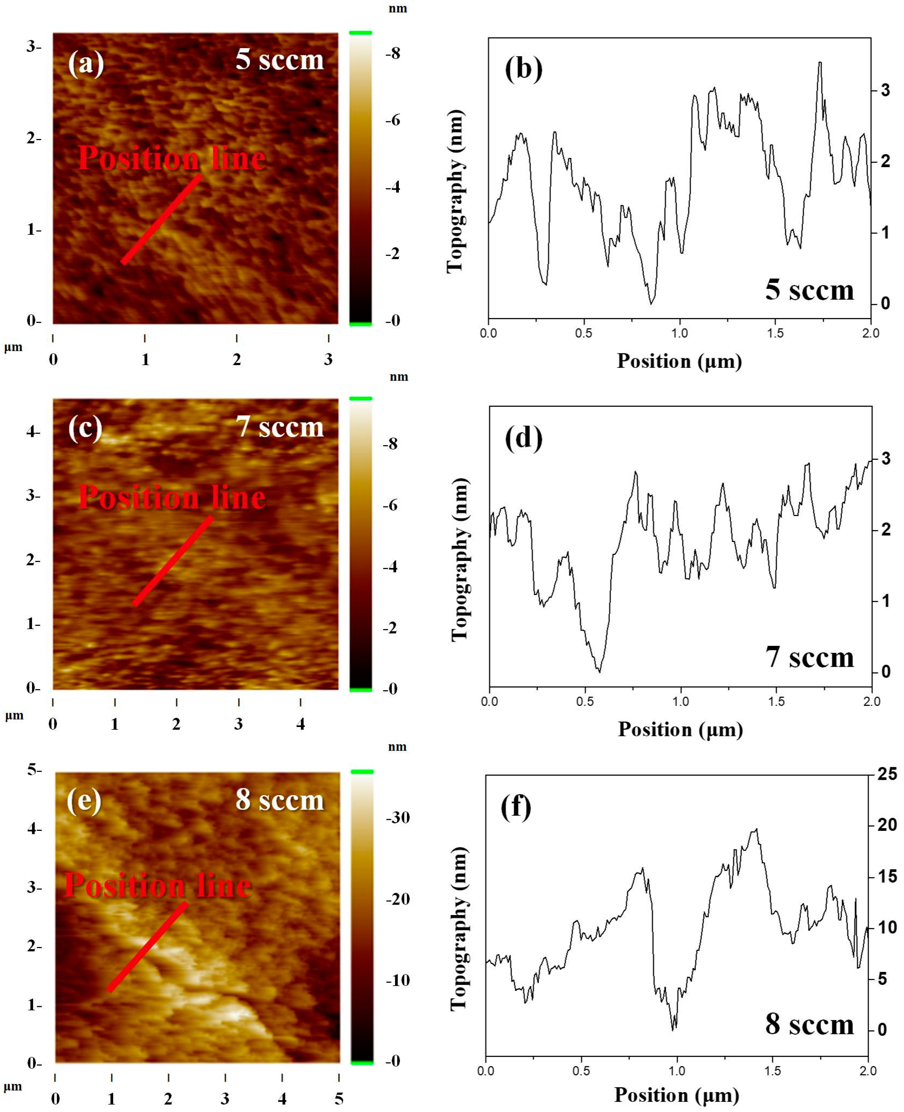
| Composition | Condition | Rrms (nm) | Cluster Size (nm) | Grain Size (nm) |
|---|---|---|---|---|
| AlCoCrNi | 5 sccm | 0.77 ± 0.03 | 38.16 ± 1.79 | 20.14 ± 0.2 |
| 7 sccm | 0.87 ± 0.04 | 75.76 ± 5.71 | 15.24 ± 0.5 | |
| 8 sccm | 2.71 ± 0.16 | 86.21 ± 3.33 | 13.35 ± 0.7 |
| Elements (at. %) | |||||
|---|---|---|---|---|---|
| Al | Co | Cr | Ni | ||
| Target materials | 24.94 | 25.09 | 24.76 | 25.21 | |
| Ar flow rate (sccm) | 5 | 24.64 | 25.42 | 24.75 | 25.31 |
| 7 | 24.43 | 25.57 | 24.84 | 25.17 | |
| 8 | 24.92 | 25.52 | 24.52 | 25.05 | |
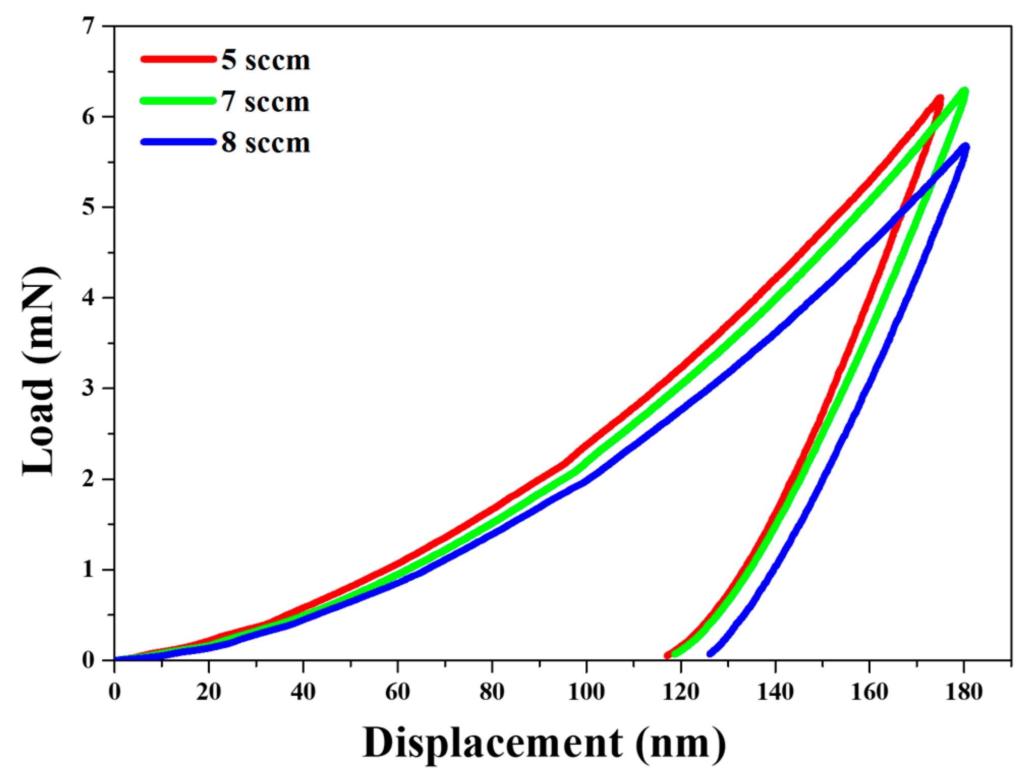
| Ar Flow Rate (sccm) | Mechanical Properties | |||
|---|---|---|---|---|
| HIT (GPa) | EIT (GPa) | HVIT (HV) | H/E | |
| 5 | 12.21 ± 1.05 | 188.1 ± 11 | 1137.1 ± 9.2 | 0.0648 ± 0.0018 |
| 7 | 11.40 ± 1.75 | 165.2 ± 19 | 1101.4 ± 15.4 | 0.0687 ± 0.0027 |
| 8 | 9.05 ± 3.19 | 141.1 ± 39 | 943.7 ± 32.5 | 0.0619 ± 0.0076 |
Disclaimer/Publisher’s Note: The statements, opinions and data contained in all publications are solely those of the individual author(s) and contributor(s) and not of MDPI and/or the editor(s). MDPI and/or the editor(s) disclaim responsibility for any injury to people or property resulting from any ideas, methods, instructions or products referred to in the content. |
© 2024 by the authors. Licensee MDPI, Basel, Switzerland. This article is an open access article distributed under the terms and conditions of the Creative Commons Attribution (CC BY) license (https://creativecommons.org/licenses/by/4.0/).
Share and Cite
Kim, Y.-S.; Park, H.-J.; Kim, Y.-S.; Hong, S.-H.; Kim, K.-B. Influence of the Gas Flow Rate on the Crack Formation of AlCoCrNi High-Entropy Metallic Film Fabricated Using Magnetron Sputtering. Coatings 2024, 14, 144. https://doi.org/10.3390/coatings14010144
Kim Y-S, Park H-J, Kim Y-S, Hong S-H, Kim K-B. Influence of the Gas Flow Rate on the Crack Formation of AlCoCrNi High-Entropy Metallic Film Fabricated Using Magnetron Sputtering. Coatings. 2024; 14(1):144. https://doi.org/10.3390/coatings14010144
Chicago/Turabian StyleKim, Young-Soon, Hae-Jin Park, Young-Seok Kim, Sung-Hwan Hong, and Ki-Buem Kim. 2024. "Influence of the Gas Flow Rate on the Crack Formation of AlCoCrNi High-Entropy Metallic Film Fabricated Using Magnetron Sputtering" Coatings 14, no. 1: 144. https://doi.org/10.3390/coatings14010144