
Influence of Bilayer Thickness on Mechanical and Tribological Properties of (Ti-Al)N/MoN Nanostructured Hard Coatings Deposited by Cathodic Arc Ion Plating
 and
and
Abstract
:1. Introduction
- 1.
- A multilayer structure encompassing TiAlN with Mo as a sublayer [19].
- 2.
- 3.
- Coatings made of multiple (TiAl)1−xMoxN components and different molybdenum concentrations [22].
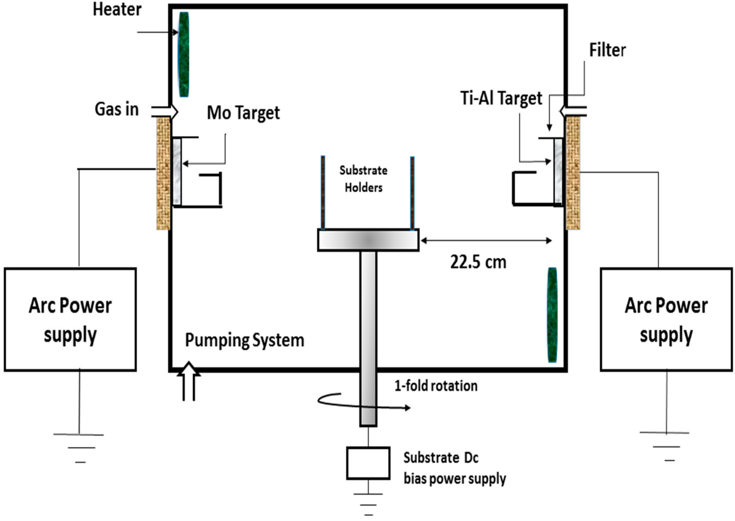
2. Materials and Methods
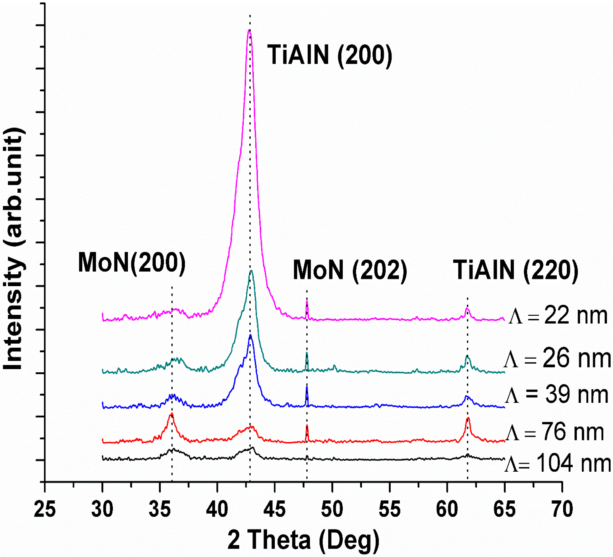
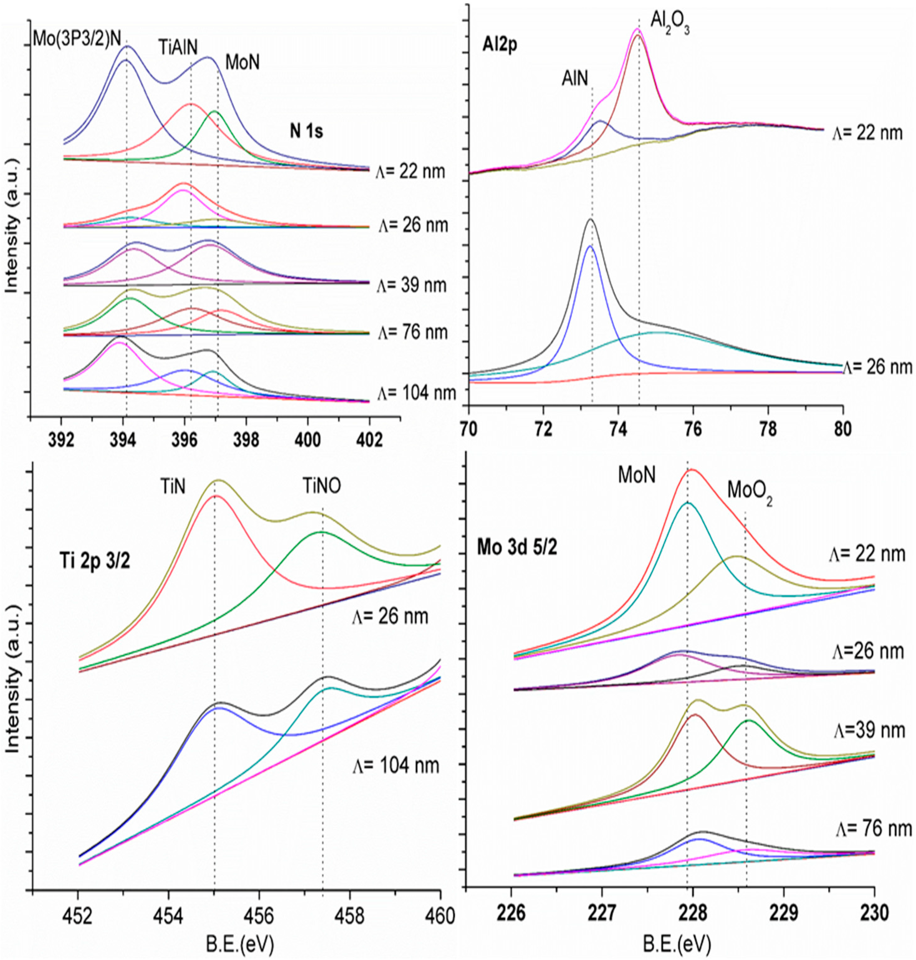
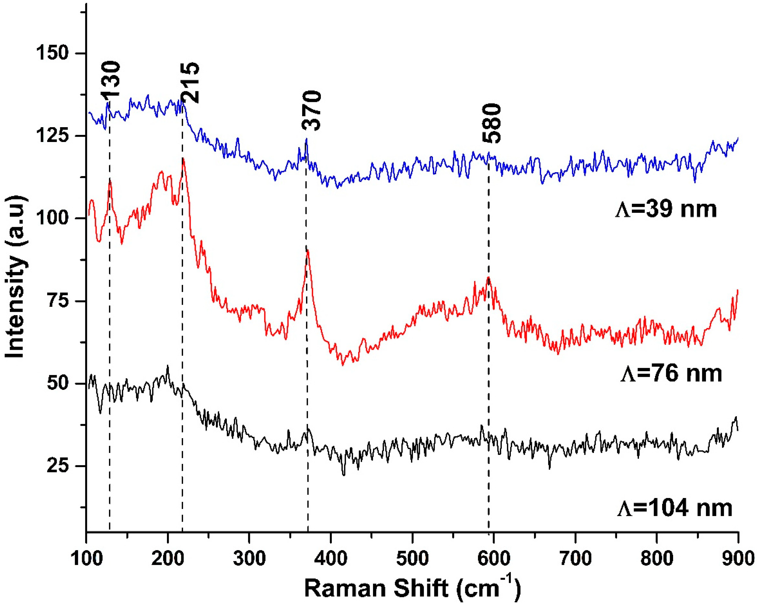
3. Results and Discussion
4. Conclusions
Author Contributions
Funding
Institutional Review Board Statement
Informed Consent Statement
Data Availability Statement
Conflicts of Interest
References
- El-Hossary, F.M.; Abd El-Rahman, A.M.; Raaif, M.; Ghareeb, D.A. Properties of TiAlN Coating Deposited by MPIIID on TiN Substrates. Appl. Phys. A Mater. Sci. Process. 2016, 122, 242. [Google Scholar] [CrossRef]
- Devia, D.M.; Restrepo-Parra, E.; Arango, P.J.; Tschiptschin, A.P.; Velez, J.M. TiAlN Coatings Deposited by Triode Magnetron Sputtering Varying the Bias Voltage. Appl. Surf. Sci. 2011, 257, 6181–6185. [Google Scholar] [CrossRef]
- Endrino, J.L.; Fox-Rabinovich, G.S.; Escobar Galindo, R.; Kalss, W.; Veldhuis, S.; Soriano, L.; Andersson, J.; Gutiérrez, A. Oxidation Post-Treatment of Hard AlTiN Coating for Machining of Hardened Steels. Surf. Coat. Technol. 2009, 204, 256–262. [Google Scholar] [CrossRef]
- Fox-Rabinovich, G.S.; Endrino, J.L.; Beake, B.D.; Aguirre, M.H.; Veldhuis, S.C.; Quinto, D.T.; Bauer, C.E.; Kovalev, A.I.; Gray, A. Effect of Temperature of Annealing below 900 °C on Structure, Properties and Tool Life of an AlTiN Coating under Various Cutting Conditions. Surf. Coat. Technol. 2008, 202, 2985–2992. [Google Scholar] [CrossRef]
- Mayrhofer, P.H.; Willmann, H.; Hultman, L.; Mitterer, C. Influence of Different Atmospheres on the Thermal Decomposition of Al-Cr-N Coatings. J. Phys. D. Appl. Phys. 2008, 41, 155316. [Google Scholar] [CrossRef]
- Hasegawa, H.; Kimura, A.; Suzuki, T. Microhardness and Structural Analysis of (Ti,Al)N, (Ti,Cr)N, (Ti,Zr)N and (Ti,V)N Films. J. Vac. Sci. Technol. A Vac. Surf. Films 2000, 18, 1038–1040. [Google Scholar] [CrossRef]
- Chawla, V.; Jayaganthan, R.; Chandra, R. Influence of Sputtering Pressure on the Structure and Mechanical Properties of Nanocomposite Ti-Si-N Thin Films. J. Mater. Sci. Technol. 2010, 26, 673–678. [Google Scholar] [CrossRef]
- McIntyre, D.; Greene, J.E.; Håkansson, G.; Sundgren, J.E.; Münz, W.D. Oxidation of Metastable Single-Phase Polycrystalline Ti0.5Al0.5N Films: Kinetics and Mechanisms. J. Appl. Phys. 1990, 67, 1542–1553. [Google Scholar] [CrossRef]
- Kimura, A.; Hasegawa, H.; Yamada, K.; Suzuki, T. Effects of Al Content on Hardness, Lattice Parameter and Microstructure of Ti1−xAlxN Films. Surf. Coat. Technol. 1999, 120–121, 438–441. [Google Scholar] [CrossRef]
- Liu, Z.-J.; Shen, Y.G. Effects of Al Content on Grain Growth of Solid Solution (Ti,Al)N Films. J. Vac. Sci. Technol. A Vac. Surf. Films 2006, 24, 174–177. [Google Scholar] [CrossRef]
- Kutschej, K.; Mayrhofer, P.H.; Kathrein, M.; Polcik, P.; Tessadri, R.; Mitterer, C. Structure, Mechanical and Tribological Properties of Sputtered Ti1−xAlxN Coatings with 0.5 ≤ x ≤ 0.75. Surf. Coat. Technol. 2005, 200, 2358–2365. [Google Scholar] [CrossRef]
- PalDey, S.; Deevi, S.C. Single Layer and Multilayer Wear Resistant Coatings of (Ti,Al)N: A Review. Mater. Sci. Eng. A 2003, 342, 58–79. [Google Scholar] [CrossRef]
- Yashar, P.C.; Sproul, W.D. Nanometer Scale Multilayered Hard Coatings. Vacuum 1999, 55, 179–190. [Google Scholar] [CrossRef]
- Cheng, Y.H.; Tay, B.K.; Lau, S.P.; Shi, X. Influence of Substrate Bias on the Structure and Properties of (Ti, Al)N Films Deposited by Filtered Cathodic Vacuum Arc. J. Vac. Sci. Technol. A Vac. Surf. Films 2001, 19, 736–742. [Google Scholar] [CrossRef]
- Rafaja, D.; Wüstefeld, C.; Baehtz, C.; Klemm, V.; Dopita, M.; Motylenko, M.; Michotte, C.; Kathrein, M. Effect of Internal Interfaces on Hardness and Thermal Stability of Nanocrystalline Ti0.5Al0.5N Coatings. Metall. Mater. Trans. A Phys. Metall. Mater. Sci. 2011, 42, 559–569. [Google Scholar] [CrossRef]
- Shum, P.W.; Li, K.Y.; Zhou, Z.F.; Shen, Y.G. Structural and Mechanical Properties of Titanium-Aluminium-Nitride Films Deposited by Reactive Close-Field Unbalanced Magnetron Sputtering. Surf. Coat. Technol. 2004, 185, 245–253. [Google Scholar] [CrossRef]
- Liu, A.; Deng, J.; Cui, H.; Chen, Y.; Zhao, J. Friction and Wear Properties of TiN, TiAlN, AlTiN and CrAlN PVD Nitride Coatings. Int. J. Refract. Met. Hard Mater. 2012, 31, 82–88. [Google Scholar] [CrossRef]
- Arndt, M.; Kacsich, T. Performance of New AlTiN Coatings in Dry and High Speed Cutting. Surf. Coat. Technol. 2003, 163, 674–680. [Google Scholar] [CrossRef]
- Tavares, C.J.; Vidrago, C.; Rebouta, L.; Rivière, J.P.; Le Bourhis, E.; Denanot, M.F. Optimization and Thermal Stability of TiAlN/Mo Multilayers. Surf. Coat. Technol. 2005, 200, 288–292. [Google Scholar] [CrossRef]
- Yousaf, M.I.; Pelenovich, V.O.; Yang, B.; Liu, C.S.; Fu, D.J. Effect of Bilayer Period on Structural and Mechanical Properties of Nanocomposite TiAlN/MoN Multilayer Films Synthesized by Cathodic Arc Ion-Plating. Surf. Coat. Technol. 2015, 282, 94–102. [Google Scholar] [CrossRef]
- Yousaf, M.I.; Pelenovich, V.O.; Yang, B.; Liu, C.S.; Fu, D.J. Influence of Substrate Rotation Speed on the Structure and Mechanical Properties of Nanocrystalline AlTiN/MoN Coatings Synthesized by Cathodic Arc Ion-Plating. Surf. Coat. Technol. 2015, 265, 117–124. [Google Scholar] [CrossRef]
- Tabakov, V.P.; Chikhranov, A.V. Influence of the Composition of Three-Element Nitride Coatings on the State and Wear of a Cutting Tool. Russ. Eng. Res. 2010, 30, 84–89. [Google Scholar] [CrossRef]
- Bhadeshia, H.K.D.H. Developments in Martensitic and Bainitic Steels: Role of the Shape Deformation. Mater. Sci. Eng. A 2004, 378, 34–39. [Google Scholar] [CrossRef]
- Riedl, H.; Koller, C.M.; Limbeck, A.; Kalaš, J.; Polcik, P.; Mayrhofer, P.H. Oxidation Behavior and Tribological Properties of Multilayered Ti-Al-N/Mo-Si-B Thin Films. J. Vac. Sci. Technol. A Vac. Surf. Films 2015, 33, 05E129. [Google Scholar] [CrossRef]
- Zhou, M.; Makino, Y.; Nose, M.; Nogi, K. Phase Transition and Properties of Ti-Al-N Thin Films Prepared by r.f.-Plasma Assisted Magnetron Sputtering. Thin Solid Films 1999, 339, 203–208. [Google Scholar] [CrossRef]
- Pemmasani, S.P.; Valleti, K.; Gundakaram, R.C.; Rajulapati, K.V.; Mantripragada, R.; Koppoju, S.; Joshi, S.V. Effect of Microstructure and Phase Constitution on Mechanical Properties of Ti1−xAlxN Coatings. Appl. Surf. Sci. 2014, 313, 936–946. [Google Scholar] [CrossRef]
- Tanaka, Y.; Gür, T.M.; Kelly, M.; Hagstrom, S.B.; Ikeda, T.; Wakihira, K.; Satoh, H. Properties of (Ti1−xAlx)N Coatings for Cutting Tools Prepared by the Cathodic Arc Ion Plating Method. J. Vac. Sci. Technol. A Vac. Surf. Films 1992, 10, 1749–1756. [Google Scholar] [CrossRef]
- Lu, J.H.; Chen, B.Y. Colored Hard Coatings with AlN–TiN Multilayer Structures. J. Vac. Sci. Technol. A Vac. Surf. Films 2014, 32, 02B106. [Google Scholar] [CrossRef]
- Kazmanli, M.K.; Ürgen, M.; Cakir, A.F. Effect of Nitrogen Pressure, Bias Voltage and Substrate Temperature on the Phase Structure of Mo-N Coatings Produced by Cathodic Arc PVD. Surf. Coat. Technol. 2003, 167, 77–82. [Google Scholar] [CrossRef]
- Ducros, C.; Benevent, V.; Sanchette, F. Deposition, Characterization and Machining Performance of Multilayer PVD Coatings on Cemented Carbide Cutting Tools. Surf. Coat. Technol. 2003, 163–164, 681–688. [Google Scholar] [CrossRef]
- Greczynski, G.; Hultman, L. Self-Consistent Modelling of X-ray Photoelectron Spectra from Air-Exposed Polycrystalline TiN Thin Films. Appl. Surf. Sci. 2016, 387, 294–300. [Google Scholar] [CrossRef]
- Prieto, P.; Kirby, R.E. X-ray Photoelectron Spectroscopy Study of the Difference between Reactively Evaporated and Direct Sputter-Deposited TiN Films and Their Oxidation Properties. J. Vac. Sci. Technol. A Vac. Surf. Films 1995, 13, 2819–2826. [Google Scholar] [CrossRef]
- Shum, P.W.; Zhou, Z.F.; Li, K.Y.; Shen, Y.G. XPS, AFM and Nanoindentation Studies of Ti1−xAlxN Films Synthesized by Reactive Unbalanced Magnetron Sputtering. Mater. Sci. Eng. B Solid-State Mater. Adv. Technol. 2003, 100, 204–213. [Google Scholar] [CrossRef]
- Greczynski, G.; Petrov, I.; Greene, J.E.; Hultman, L. Al Capping Layers for Nondestructive X-ray Photoelectron Spectroscopy Analyses of Transition-Metal Nitride Thin Films. J. Vac. Sci. Technol. A Vac. Surf. Films 2015, 33, 05E101. [Google Scholar] [CrossRef]
- Choi, J.G.; Thompson, L.T. XPS Study of As-Prepared and Reduced Molybdenum Oxides. Appl. Surf. Sci. 1996, 93, 143–149. [Google Scholar] [CrossRef]
- Spengler, W.; Kaiser, R. First and Second Order Raman Scattering in Transition Metal Compounds. Solid State Commun. 1976, 18, 881–884. [Google Scholar] [CrossRef]
- Spengler, W.; Kaiser, R.; Christensen, A.N.; Müller-Vogt, G. Raman Scattering, Superconductivity, and Phonon Density of States of Stoichiometric and Nonstoichiometric TiN. Phys. Rev. B 1978, 17, 1095–1101. [Google Scholar] [CrossRef]
- Franck, M.; Celis, J.P. Microprobe Raman Spectroscopy of TiN Coatings Oxidized by Solar Beam Heat Treatment. J. Mater. Res. 1995, 10, 119–125. [Google Scholar] [CrossRef]
- Bondarev, A.V.; Kiryukhantsev-Korneev, P.V.; Sheveyko, A.N.; Shtansky, D.V. Structure, Tribological and Electrochemical Properties of Low Friction TiAlSiCN/MoSeC Coatings. Appl. Surf. Sci. 2015, 327, 253–261. [Google Scholar] [CrossRef]
- Soignard, E.; Shebanova, O.; McMillan, P.F. Compressibility Measurements and Phonon Spectra of Hexagonal Transition-Metal Nitrides at High Pressure: ε-TaN, δ-MoN, and Cr2N. Phys. Rev. B Condens. Matter Mater. Phys. 2007, 75, 014104. [Google Scholar] [CrossRef]
- Barshilia, H.C.; Rajam, K.S. Raman Spectroscopy Studies on the Thermal Stability of TiN, CrN, TiAIN Coatings and Nanolayered TiN/CrN, TiAIN/CrN Multilayer Coatings. J. Mater. Res. 2004, 19, 3196–3205. [Google Scholar] [CrossRef]
- Huang, S.H.; Chen, S.F.; Kuo, Y.C.; Wang, C.J.; Lee, J.W.; Chan, Y.C.; Chen, H.W.; Duh, J.G.; Hsieh, T.E. Mechanical and Tribological Properties Evaluation of Cathodic Arc Deposited CrN/ZrN Multilayer Coatings. Surf. Coat. Technol. 2011, 206, 1744–1752. [Google Scholar] [CrossRef]
- Settineri, L.; Levi, R. Surface Properties and Performance of Multilayer Coated Tools in Turning Inconel. CIRP Ann. Manuf. Technol. 2005, 54, 515–518. [Google Scholar] [CrossRef]
- Valli, J.; Mäkelä, U.; Matthews, A.; Murawa, V. TiN Coating Adhesion Studies Using the Scratch Test Method. J. Vac. Sci. Technol. A Vac. Surf. Films 1985, 3, 2411–2414. [Google Scholar] [CrossRef]
- Suzuki, T.; Huang, D.; Ikuhara, Y. Microstructures and Grain Boundaries of (Ti,Al)N Films. Surf. Coat. Technol. 1998, 107, 41–47. [Google Scholar] [CrossRef]
- Lin, K.L.; Hwang, M.Y.; Wu, C.D. The Deposition and Wear Properties of Cathodic Arc Plasma Deposition TiAlN Deposits. Mater. Chem. Phys. 1996, 46, 77–83. [Google Scholar] [CrossRef]
- Musil, J. Hard Nanocomposite Coatings: Thermal Stability, Oxidation Resistance and Toughness. Surf. Coat. Technol. 2012, 207, 50–65. [Google Scholar] [CrossRef]
- Chu, X.; Barnett, S.A. Model of Superlattice Yield Stress and Hardness Enhancements. J. Appl. Phys. 1995, 77, 4403–4411. [Google Scholar] [CrossRef]
- Mooser, E. Bonds and Bands in Semiconductors. Cryst. Semicond. Mater. Devices 1988, 169, 1–54. [Google Scholar] [CrossRef]
- Musil, J.; Kunc, F.; Zeman, H.; Poláková, H. Relationships between Hardness, Young’s Modulus and Elastic Recovery in Hard Nanocomposite Coatings. Surf. Coat. Technol. 2002, 154, 304–313. [Google Scholar] [CrossRef]
- Gulbinski, W.; Suszko, T.; Sienicki, W.; Warcholiński, B. Tribological Properties of Silver-and Copper-Doped Transition Metal Oxide Coatings. Wear 2003, 254, 129–135. [Google Scholar] [CrossRef]
- Suszko, T.; Gulbiński, W.; Jagielski, J. The Role of Surface Oxidation in Friction Processes on Molybdenum Nitride Thin Films. Surf. Coat. Technol. 2005, 194, 319–324. [Google Scholar] [CrossRef]
- Kutschej, K.; Mayrhofer, P.H.; Kathrein, M.; Polcik, P.; Mitterer, C. Influence of Oxide Phase Formation on the Tribological Behaviour of Ti-Al-V-N Coatings. Surf. Coat. Technol. 2005, 200, 1731–1737. [Google Scholar] [CrossRef]
- Pfeiler, M.; Kutschej, K.; Penoy, M.; Michotte, C.; Mitterer, C.; Kathrein, M. The Effect of Increasing V Content on Structure, Mechanical and Tribological Properties of Arc Evaporated Ti-Al-V-N Coatings. Int. J. Refract. Met. Hard Mater. 2009, 27, 502–506. [Google Scholar] [CrossRef]
- Zhou, Z.; Rainforth, W.M.; Rodenburg, C.; Hyatt, N.C.; Lewis, D.B.; Hovsepian, P.E. Oxidation Behavior and Mechanisms of TiAlN/VN Coatings. Metall. Mater. Trans. A Phys. Metall. Mater. Sci. 2007, 38, 2464–2478. [Google Scholar] [CrossRef]
- Ávila, R.F.; Mancosu, R.D.; Machado, A.R.; Vecchio, S.D.; da Silva, R.B.; Vieira, J.M. Comparative Analysis of Wear on PVD TiN and (Ti1−xAlx)N Coatings in Machining Process. Wear 2013, 302, 1192–1200. [Google Scholar] [CrossRef]


| Deposition Parameters | |
|---|---|
| Base pressure (Pa) | 3.4 × 10⁻³ |
| Cathode targets | Ti0.50Al0.50 and Mo |
| Ar+ bombard for cleaning | −600 V bias voltage with 80% duty cycle for 30 min |
| Source to substrate distance (cm) | 22.5 |
| Substrate bias voltage (−V) | 150 |
| Substrate temperature (°C) | 325 |
| Cathodic arc current (A) | 60 for TiAl and 80 for Mo targets |
| Reactive gas | N2 |
| Reactive gas pressure (Pa) | 2.5 |
| Substrate holder rotation speed (rpm) | 1, 2, 3, 4, 5 |
| Deposition time (minutes) | 30 |
| Interlayer(s) | Mo (−200 V Time = 8 min, P = 3.1 × 10⁻² Pa, current = 80 A) |
| Rotational mode | 1-Fold rotation |
| Λ (nm) | Element Composition [at%] | Thickness (Ti-Al)N/MoN (µm) | Grain Size TiAlN (nm) | Grain Size MoN (nm) | |||
|---|---|---|---|---|---|---|---|
| Ti K | Al K | Mo L | N K | ||||
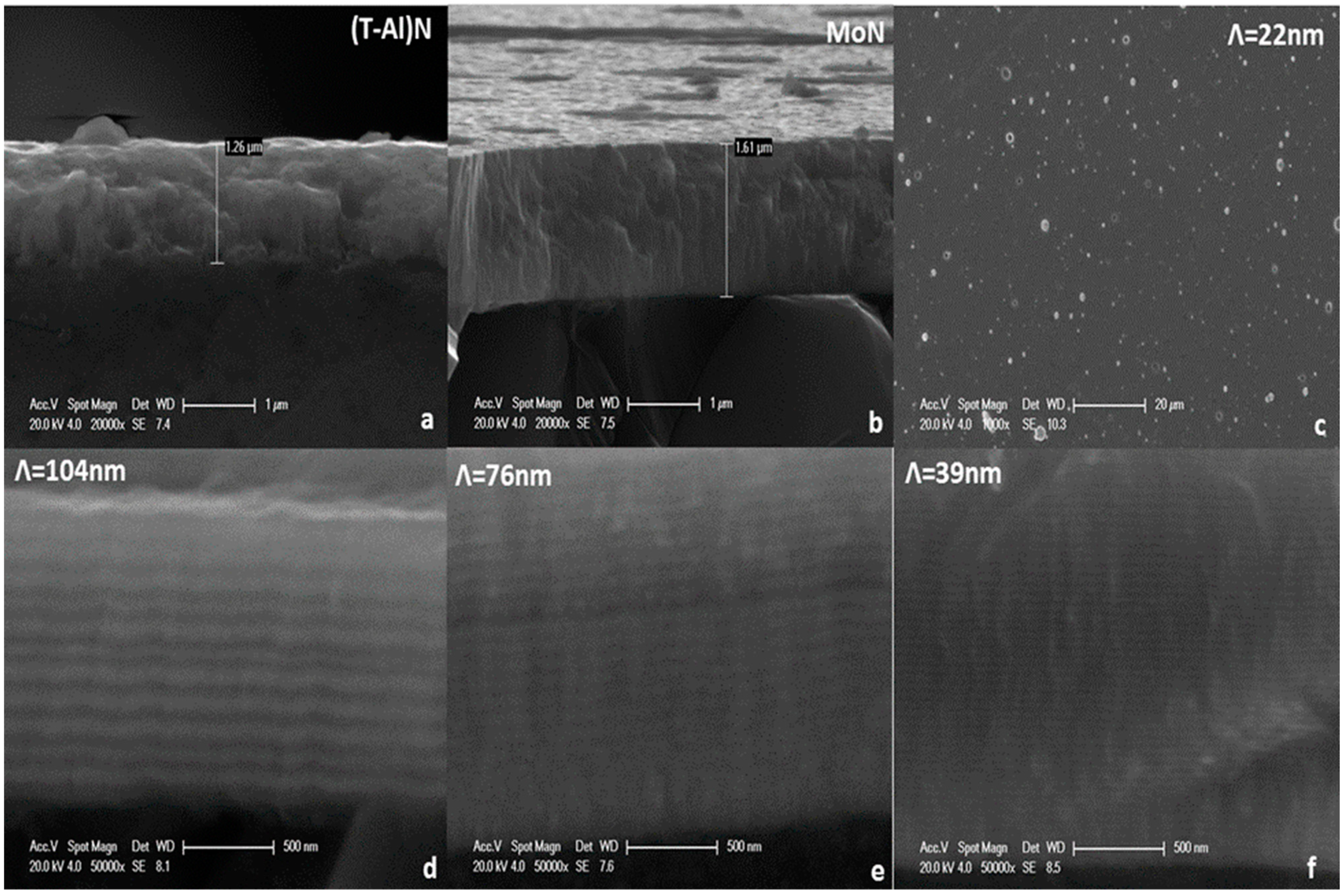
| 104 | 17.49 | 15.54 | 43.25 | 23.72 | 1.33 ± 0.04 | 7.42 ± 0.2 | 7.08 ± 0.3 |
| 76 | 13.59 | 12.91 | 40.45 | 33.05 | 1.69 ± 0.02 | 6.91 ± 0.1 | 10 ± 0.4 |
| 39 | 16.82 | 15.91 | 43.21 | 24.06 | 1.91 ± 0.02 | 6.45 ± 0.2 | 8.60 ± 0.3 |
| 26 | 14.97 | 15.70 | 33.46 | 35.87 | 1.95 ± 0.04 | 6.77 ± 0.1 | 5.80 ± 0.3 |
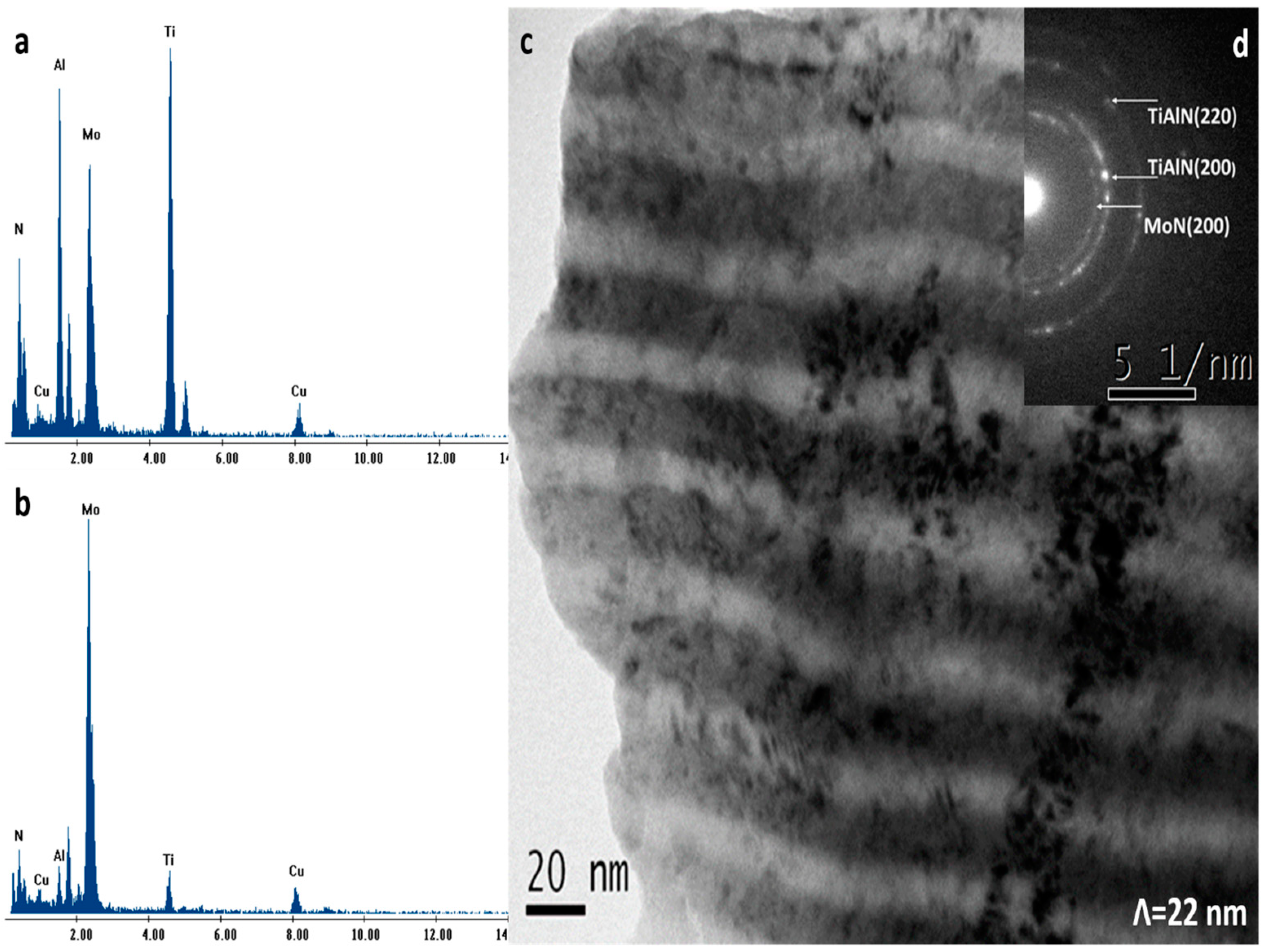
| 22 | 12.67 | 11.38 | 37.82 | 38.12 | 2.91 ± 0.03 | 6.06 ± 0.1 | 4.17 ± 0.2 |
| (Ti-Al)N | 25.89 | 25.15 | - | 48.97 | 1.26 ± 0.03 | 5.48 ± 0.1 | - |
| MoN | - | - | 59.02 | 40.98 | 1.61 ± 0.04 | - | 14.59 ± 0.2 |
| Λ (nm) | Roughness (RMS) nm | Friction Coef. | Hardness (GPa) | Elastic Modulus (GPa) | H/E* | H3/E*2 (GPa) | Wear Rate (mm3/N·m) | Critical Load (N) |
|---|---|---|---|---|---|---|---|---|
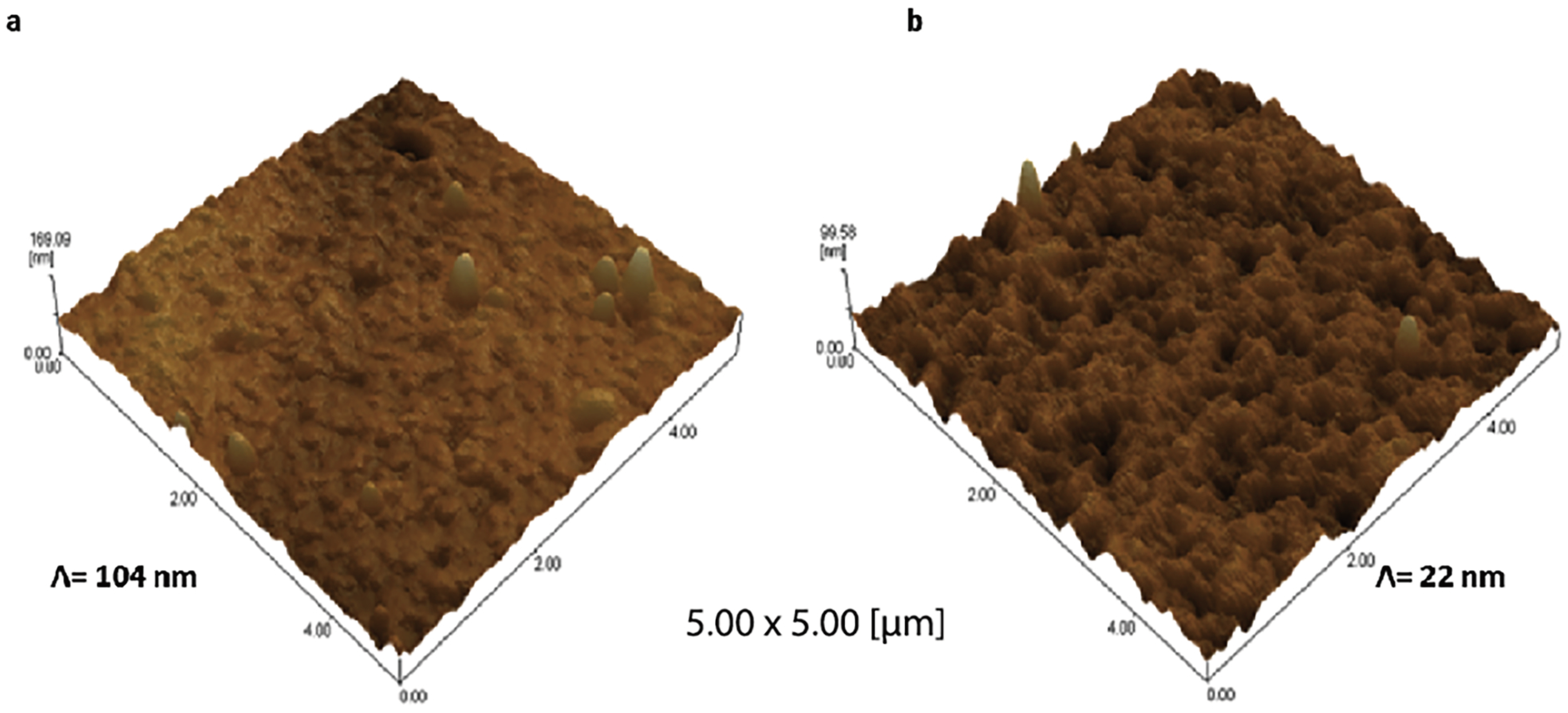
| 104 | 15.60 | 0.52 ± 0.03 | 33 ± 1.5 | 575 ± 25 | 0.055 | 0.101 | 1.56 × 10⁻⁶ | 78 ± 5 (LC1) |
| 76 | 13.73 | 0.50 ± 0.04 | 32 ± 0.5 | 500 ± 30 | 0.061 | 0.122 | 2.10 × 10⁻⁶ | 87 ± 3 (LC1) |
| 39 | 23.01 | 0.42 ± 0.02 | 34 ± 0.5 | 510 ± 30 | 0.064 | 0.141 | 1.29 × 10⁻⁶ | 71 ± 4 (LC1) |
| 26 | 17.9 | 0.39 ± 0.02 | 37 ± 0.5 | 540 ± 20 | 0.066 | 0.162 | 1.45 × 10⁻⁶ | 75 ± 5 (LC1) |
| 22 | 8.52 | 0.38 ± 0.07 | 32 ± 2 | 600 ± 20 | 0.051 | 0.085 | 8.09 × 10⁻⁷ | 91 ± 3 (LC1) |
| (Ti-Al)N | 27.78 | 0.53 ± 0.04 | 30 ± 2 | 470 ± 20 | 0.061 | 0.114 | 1.56 × 10⁻⁵ | 75 ± 3 (LC1) |
| MoN | 7.50 | 0.38 ± 0.02 | 31 ± 1 | 550 ± 15 | 0.054 | 0.092 | 5.36 × 10⁻⁷ | >100 (LC1) |
Disclaimer/Publisher’s Note: The statements, opinions and data contained in all publications are solely those of the individual author(s) and contributor(s) and not of MDPI and/or the editor(s). MDPI and/or the editor(s) disclaim responsibility for any injury to people or property resulting from any ideas, methods, instructions or products referred to in the content. |
© 2023 by the authors. Licensee MDPI, Basel, Switzerland. This article is an open access article distributed under the terms and conditions of the Creative Commons Attribution (CC BY) license (https://creativecommons.org/licenses/by/4.0/).
Share and Cite
Yousaf, M.I.; Abudouwufu, T.; Yang, B.; Tolstoguzov, A.; Fu, D. Influence of Bilayer Thickness on Mechanical and Tribological Properties of (Ti-Al)N/MoN Nanostructured Hard Coatings Deposited by Cathodic Arc Ion Plating. Coatings 2023, 13, 1654. https://doi.org/10.3390/coatings13091654
Yousaf MI, Abudouwufu T, Yang B, Tolstoguzov A, Fu D. Influence of Bilayer Thickness on Mechanical and Tribological Properties of (Ti-Al)N/MoN Nanostructured Hard Coatings Deposited by Cathodic Arc Ion Plating. Coatings. 2023; 13(9):1654. https://doi.org/10.3390/coatings13091654
Chicago/Turabian StyleYousaf, Muhammad I., Tushagu Abudouwufu, Bing Yang, Alexander Tolstoguzov, and Dejun Fu. 2023. "Influence of Bilayer Thickness on Mechanical and Tribological Properties of (Ti-Al)N/MoN Nanostructured Hard Coatings Deposited by Cathodic Arc Ion Plating" Coatings 13, no. 9: 1654. https://doi.org/10.3390/coatings13091654