1. Introduction
Recent years have seen an increased demand for titanium and its alloys in various sectors of the economy. The great interest in these materials results primarily from their high specific strength, low density, heat resistance and cracking resistance at low temperatures, and excellent corrosion resistance under operating conditions. Titanium alloys are used to produce, among others, compressor blades, wheel support beams, heat exchangers, condensers, desalination systems, profiling tools, valves, and other machine parts. The limitation of using titanium alloys for machine and device components is their low hardness and resistance to abrasive wear [
1,
2].
Wear is a process that occurs on interacting elements of machines and devices in motion. Most often, it is mechanical in nature. Less often, it is mechanical combined with the chemical action of the surrounding medium [
3].
The resistance of a material to wear is dependent on the topography of its outermost layer obtained in a technological process. The author of [
4] defines the top surface as a set of components comprising the surface physicochemical (microstructure, its mechanical and physicochemical properties) and stereometric (roughness, shape deviation and flaws) characteristics. Since all these components affect the service life of machine elements and depend on many factors, e.g., material properties, finishing technology, functional properties of the produced surface, and operating conditions [
5,
6], the element surface is a key player in machine operation. Surfaces are subject to modification due to friction, external forcing, and impact time. The initial values of stereometric and physicochemical parameters change to produce an operational surface layer [
4]. Closely related to the concept of friction is the phenomenon of wear. It occurs on the surface layers of interacting solids, leading to changes in the structure and physicochemical properties of sliding elements, their dimensions, shape, and mass loss [
7,
8].
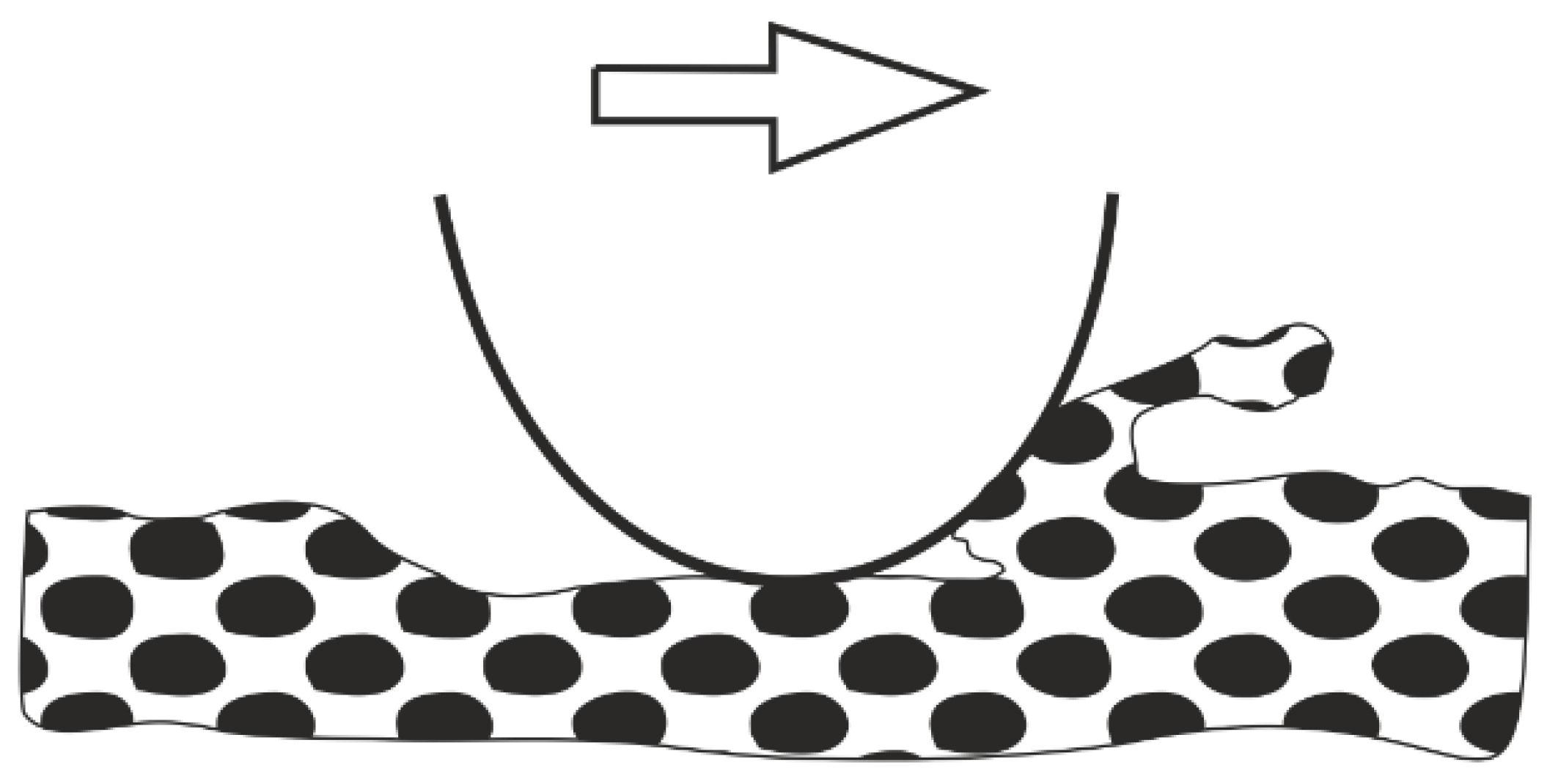
In machine parts, the predominant type of interaction between two or more components is sliding friction, with abrasive wear as the main wear type (
Figure 1) [
9,
10].
According to Płaza et al. [
11], abrasive wear dominates under dry friction and comprises about 80%–90% of all tribological wear. It is most often formed as a result of the movement of wear products (hard abrasive particles between frictionally interacting elements). To counteract wear, surface layers are modified or lubricants suitable for a given technical application are used. Antiwear technologies are gathering momentum with their capability of enhancing the durability of components operating under variable tribological and non-tribological loads. Antiwear technologies find applications across diverse areas, such as tooling, automotive production, chemical industry, food processing, medicine, and others [
12,
13]. In many industrial applications, commonly used conventional technologies do not meet the requirements for modern machinery and equipment components.
Surface engineering techniques based on unconventional technologies, such as electrochemical and chemical deposition [
14], electrical discharge machining and laser beam machining [
15,
16,
17,
18], increasingly popular 3D printing [
19], modern coating-forming methods based on physical and chemical vapor deposition (PVD, CVD) [
12,
13,
14], and ion implantation [
20], are making a significant impact. Advanced surface-coating techniques enable a large range of surface modifications in order to obtain the functional properties, including tribological properties of the top layer. Various surface modification techniques (polishing, sandblasting, etching), ion implantation, or deposition of thin hard coatings are available [
21,
22,
23,
24]. Examples include diamond-like carbon (DLC) coating type a-C:H characterized by high hardness due to sp
3 bonds (typical in diamond) and excellent lubrication properties due to sp
2 bonds (typical in graphite) [
25,
26,
27,
28,
29].
DLC coatings display excellent mechanical properties, such as high elastic modulus, resistance to brittle fracture, and chemical stability. These characteristics allow them to be used in tribological systems where a low coefficient of friction and high resistance to friction wear are required, i.e., in the transportation equipment, tooling, textile, medical, and plastics processing industries [
30,
31].
The challenging downside of DLC coating properties is high residual stress, which can inhibit the coating adhesion to the substrate. To prevent this, intermediate layers are deposited, or the coatings are doped with other elements [
32,
33,
34,
35,
36].
Research conducted by Kim et al. [
37] indicated that non-lubricated friction nodes with Si-DLC may have lower friction coefficients than DLC and that friction coefficients decrease with increasing Si content in DLC. Research by [
38] proved that Si-DLC friction pairs exhibited lower wear when lubricated with a lubricant used in belt conveyors. Moreover, according to [
39], the addition of Si improved the adhesion and increased the thermal stability of DLC layers. In [
40], the authors examined the tribological properties of diamond-like coatings and coatings doped with silicon and tungsten. The tests were carried out in reciprocating motion, without lubrication, and with an amplitude of 1, 6, and 36 Hz. The test results indicated that, when using an amplitude of 1 and 6 Hz, the Si-DLC coating was characterized by lower average friction coefficients than DLC and W-DLC.
DLC coatings can be obtained by chemical vapor deposition (CVD) [
1,
32,
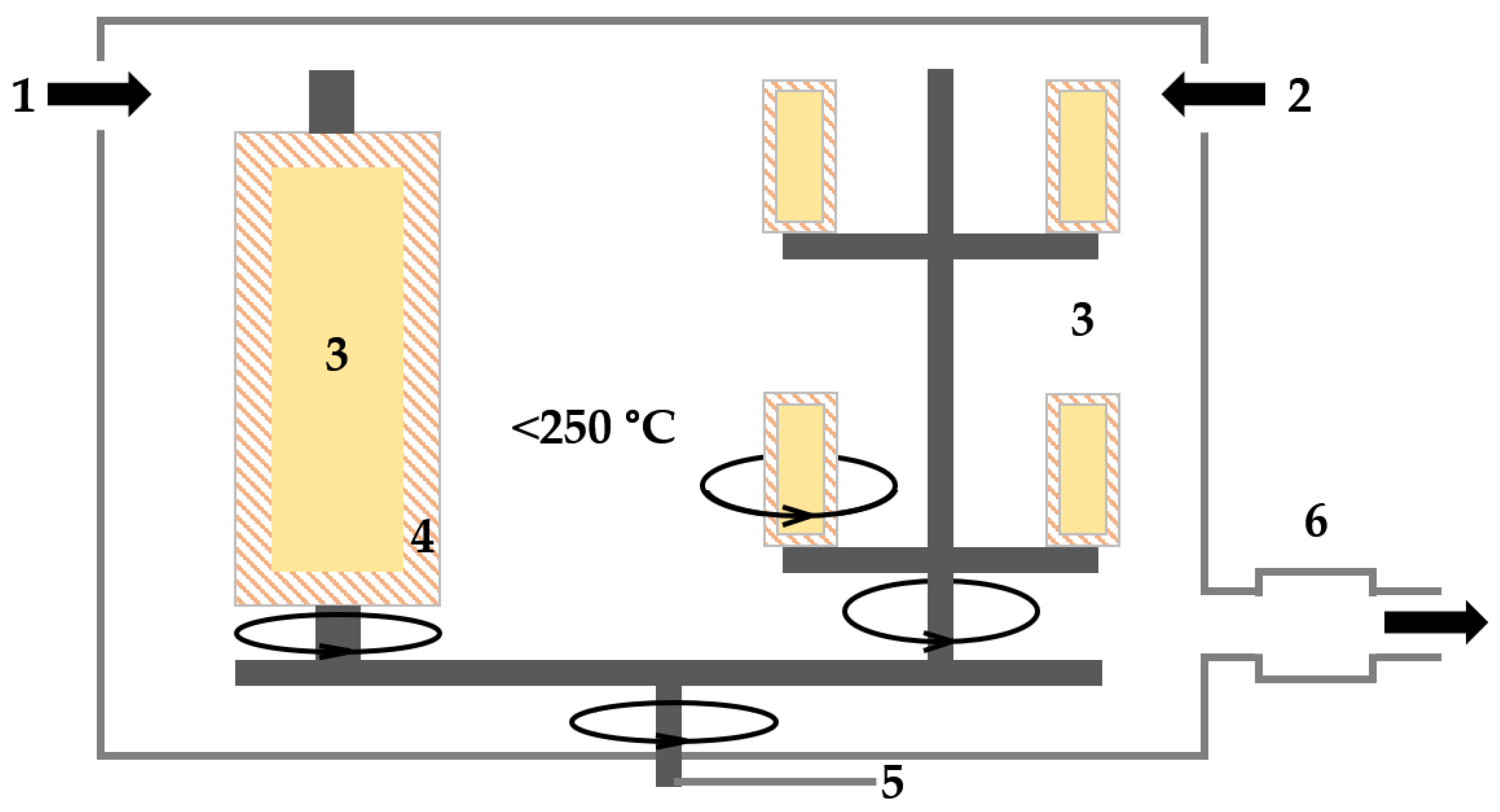
41] or hybrid methods that use the CVD process characteristics. In the process, chemical compounds (known as precursors) are introduced into the reaction chamber in the form of a gas activated to become more reactive and then deposited on the substrate as a thin film. CVD techniques require the use of high temperatures, 900–1100 °C or higher, in order for the reactants to decompose properly and for chemical reactions to proceed. This significantly limits their application range, for example, on components subjected to dynamic operational loads [
2]. Plasma enhancement of the conventional CVD process produces a plasma-assisted chemical vapor deposition (PACVD) technique that allows the lowering of the deposition temperature to <250 °C [
42]. The innovative coating manufacturing techniques produce surfaces with improved mechanical and tribological properties for an increased service life of machine and equipment components [
43].
The literature analysis indicates that no research has been conducted on assessing the effects of surface treatments such as polishing and sandblasting or a-C:H:Si coatings on the properties of titanium alloys. Therefore, this study attempted to examine their influence on the properties of the Ti13Nb13Zr alloy. Surface geometry, as well as mechanical and physicochemical properties, were comprehensively characterized. The essential element of this study was the assessment of the applied treatments on the tribological properties of the titanium alloy under dry friction and BeCool Met 3920 coolant lubricated friction. No reports on using the proposed lubricant have been published in the literature. In addition, wear mechanisms occurring between interacting elements were determined.
The test results showed that surface treatments and antiwear coatings on friction pair elements, additionally supported by a lubricant, reduced the intensity of wear of the Ti13Nb13Zr titanium alloy.
3. Results
3.1. Adhesion and Hardness
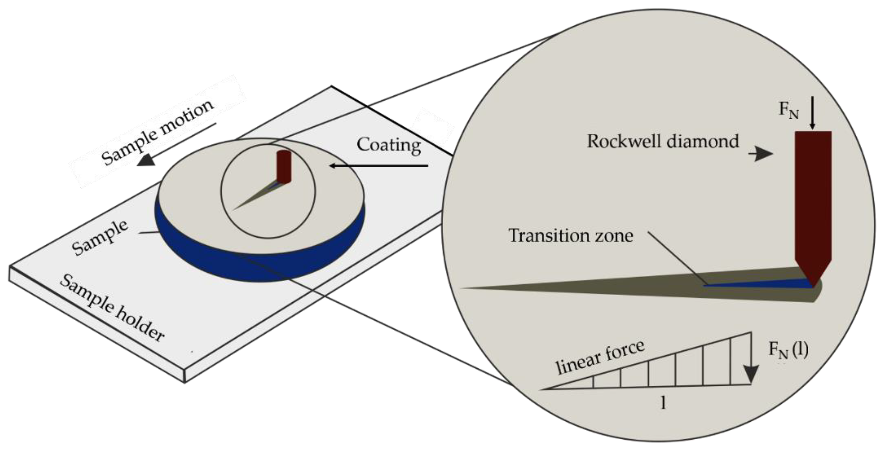
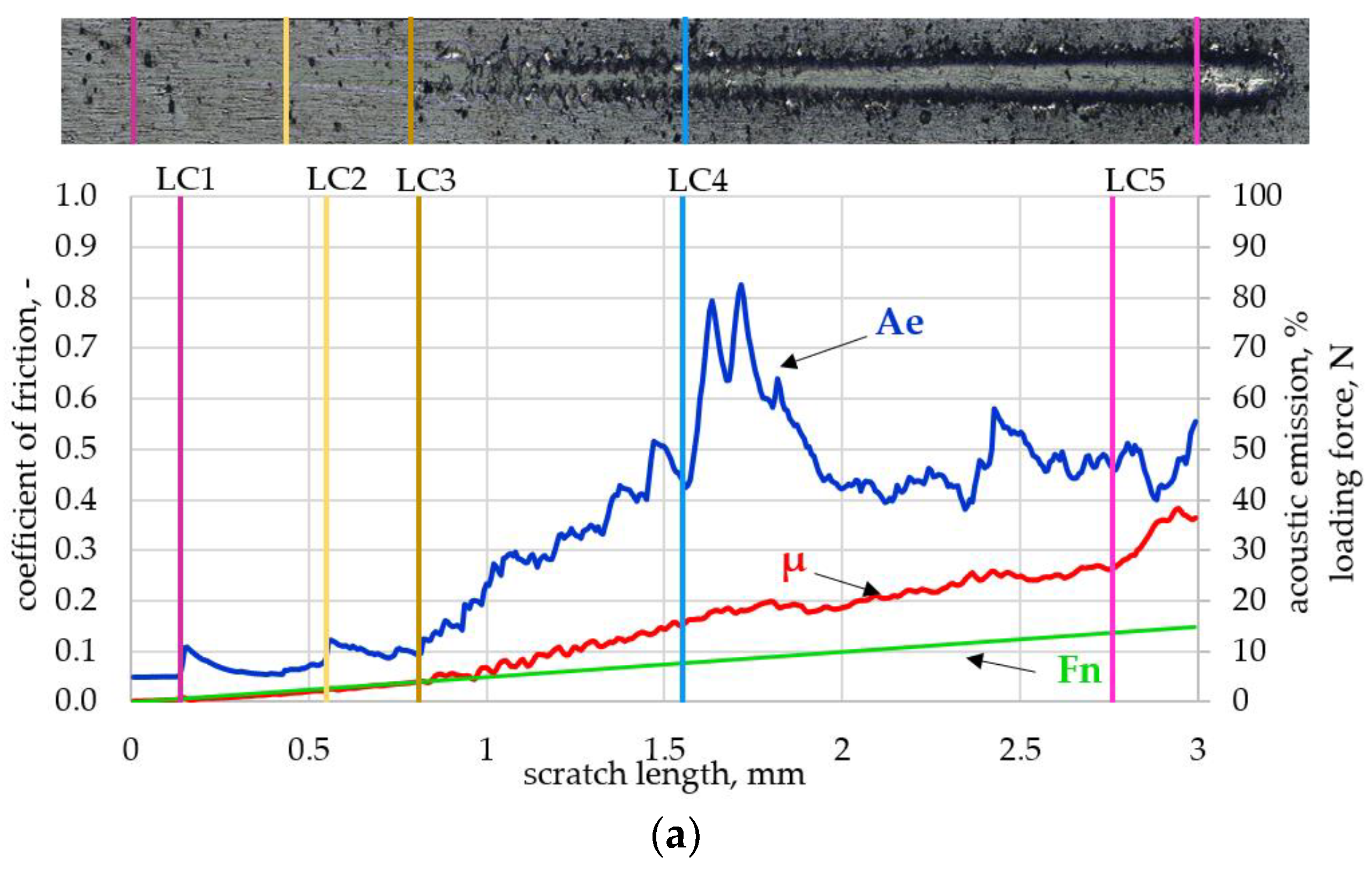
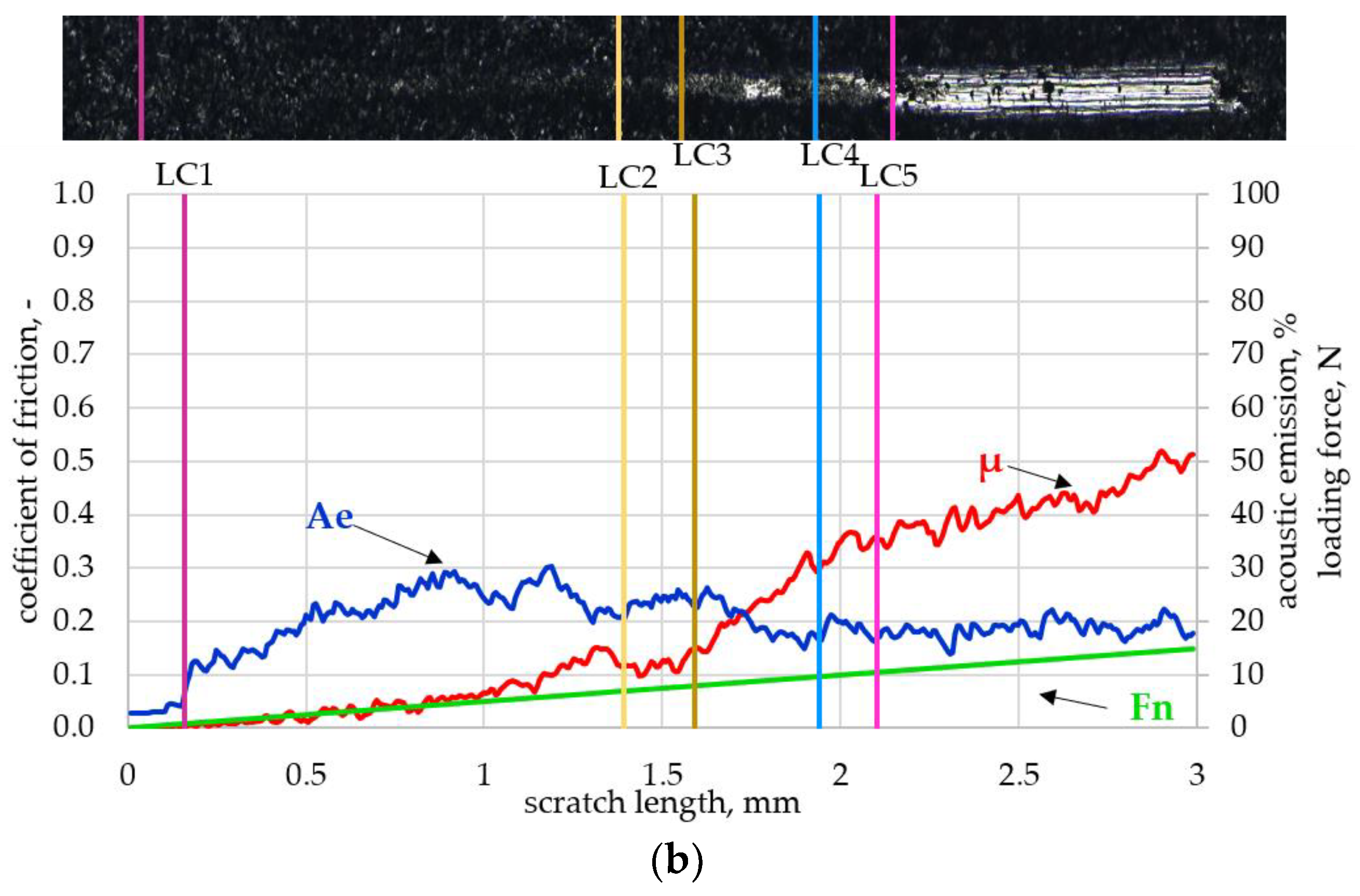
Figure 8 shows the results of the scratch test of a-C:H:Si coatings deposited on the polished (a) and sandblasted (b) surfaces. The diagrams show optical images of the scratches as well as plots of friction coefficients—µ, loading force (Fn), acoustic emission (Ae)—and the values of critical forces (LC
1–LC
5).
The results of the scratch test of the a-C:H coating deposited on the polished surface indicated its good adhesion to the Ti13Nb13Zr substrate. Although characteristic peaks were observed on the acoustic emission plot and cracks and pitting were observed on the optical image, ultimately, the coating remained unbroken. On the sandblasted sample under an FN load of about 10.5 N, the applied carbon layer delaminated. The tests indicated a relationship between roughness and adhesion to the metallic substrate. The coating deposited on the less-textured sample had better adhesion than the layer applied to the sandblasted surface.
Table 3 shows the average values of essential mechanical parameters: instrumental hardness (HIT), Young’s modulus (EIT), and maximum indenter penetration depth (hm) calculated based on five measurement series.
Mechanical tests showed changes in Ti13Nb13Zr alloy hardness and Young’s modulus due to the deposition of diamond-like coatings. Both parameters increased by almost 82% and 42%, respectively. The indenter penetration depth (hm) was closely related to HIT and EIT values. The sample with the diamond-like coating produced the smallest indentation, 177 nm. The tribological characteristics of the analyzed materials, including wear resistance, were expected to be directly impacted by the increase in hardness.
3.2. Coating Thickness
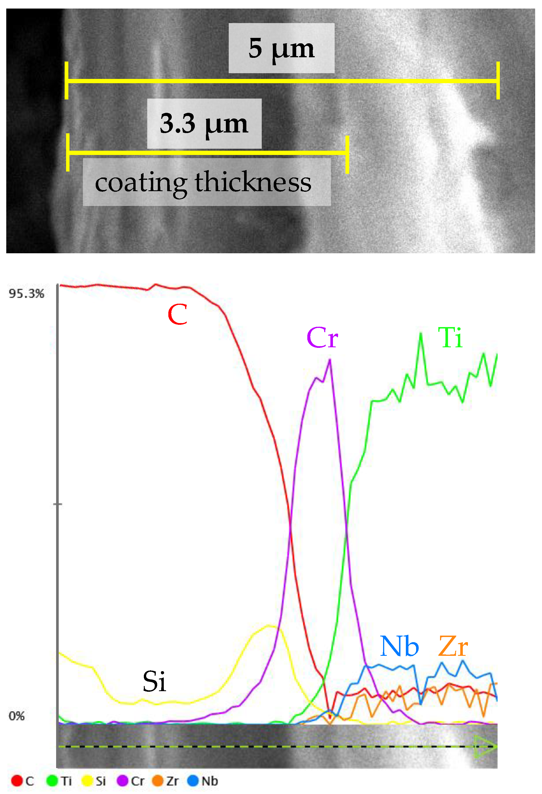
Figure 9 shows a cross-sectional image of the a-C:H:Si coating microstructure along with the linear distribution of elements. The thickness of the coating was determined from observations in three areas.
Linear analysis of the elemental distribution in the diamond-like coating showed that the near-surface layer consisted of carbon and silicon. At a depth of about 2.6 µm from the surface, the interlayer of chromium was observed. Its function was to ensure adequate coating-to-metallic substrate adhesion. The analysis also indicated the presence of titanium, niobium, and zirconium (elements derived from the substrate).
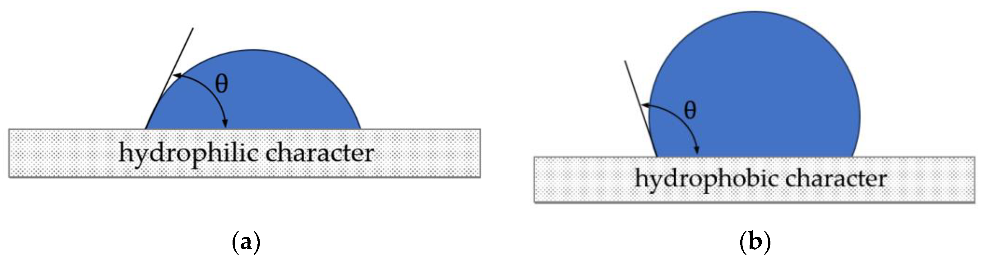
3.3. Contact Angle and Surface Tension
The wettability of the surface and the energy of the materials play an important role during the operation of tribological systems.
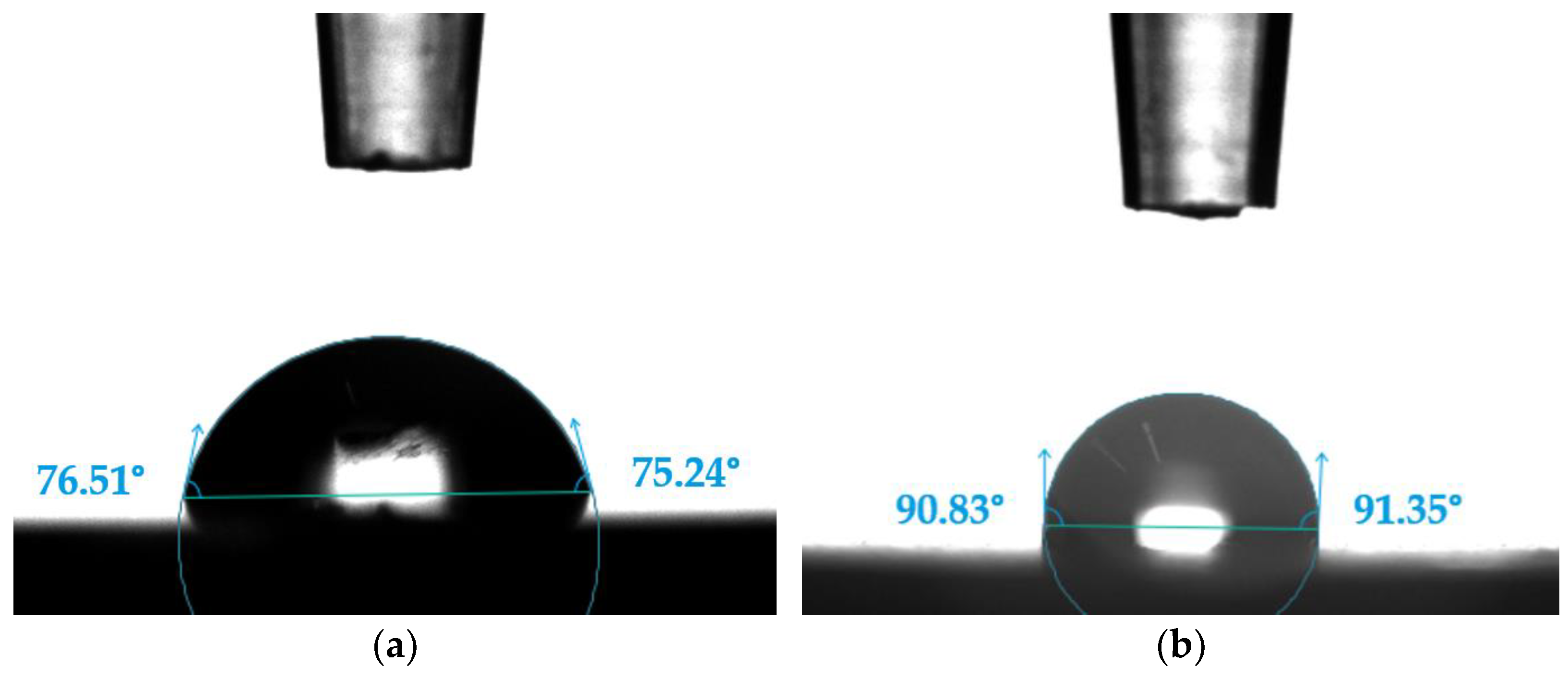
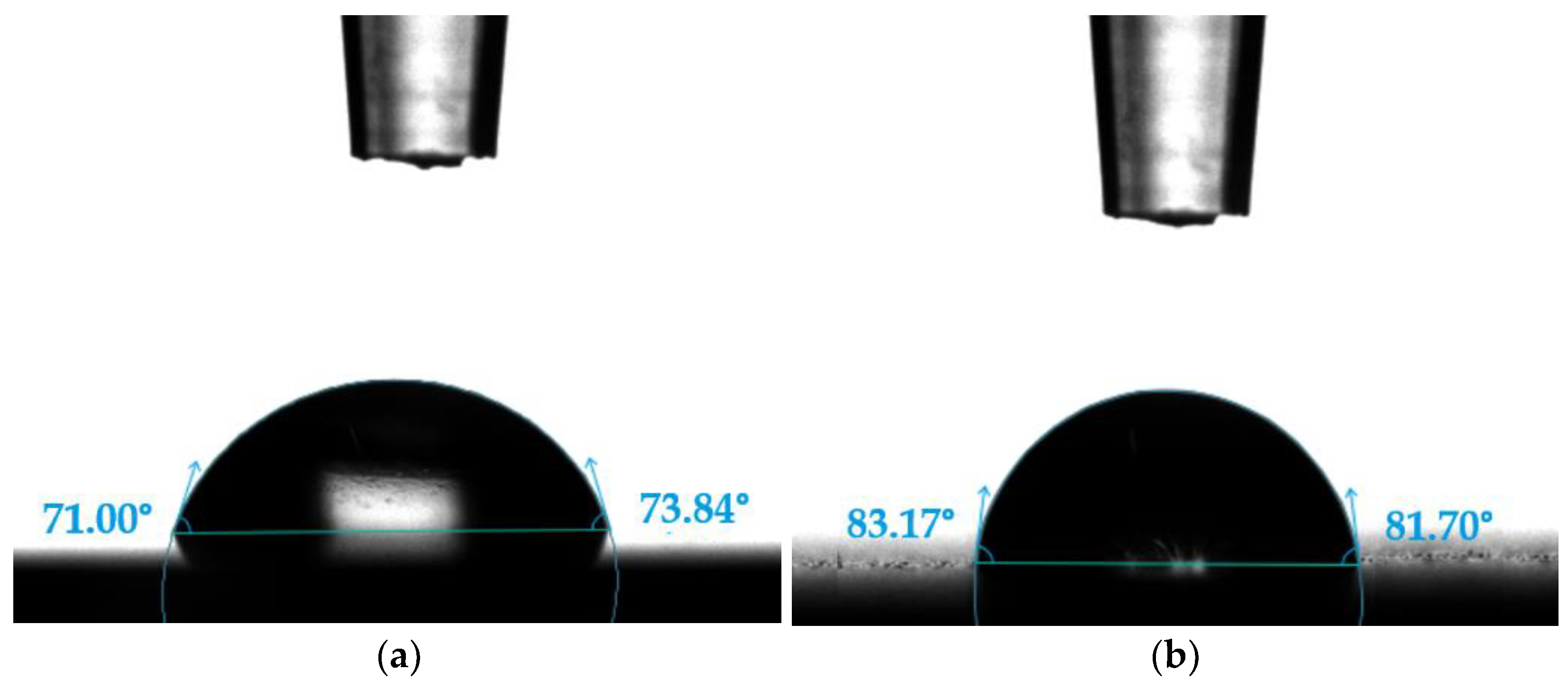
Figure 10 and
Figure 11 show example photos of demineralized water droplets deposited on carbon coatings. In turn,
Table 4 and
Table 5 summarize the average results of the recorded contact angles and surface tension.
The results presented above indicate that surface topography affected the values of contact angles and surface tension. Although both samples tested showed hydrophilic character, the carbon coating deposited on the polished surface had about 13% lower contact angles than the coating deposited on the sandblasted surface. The value of surface tension decreased with increasing surface roughness.
3.4. Confocal Microscopy Results
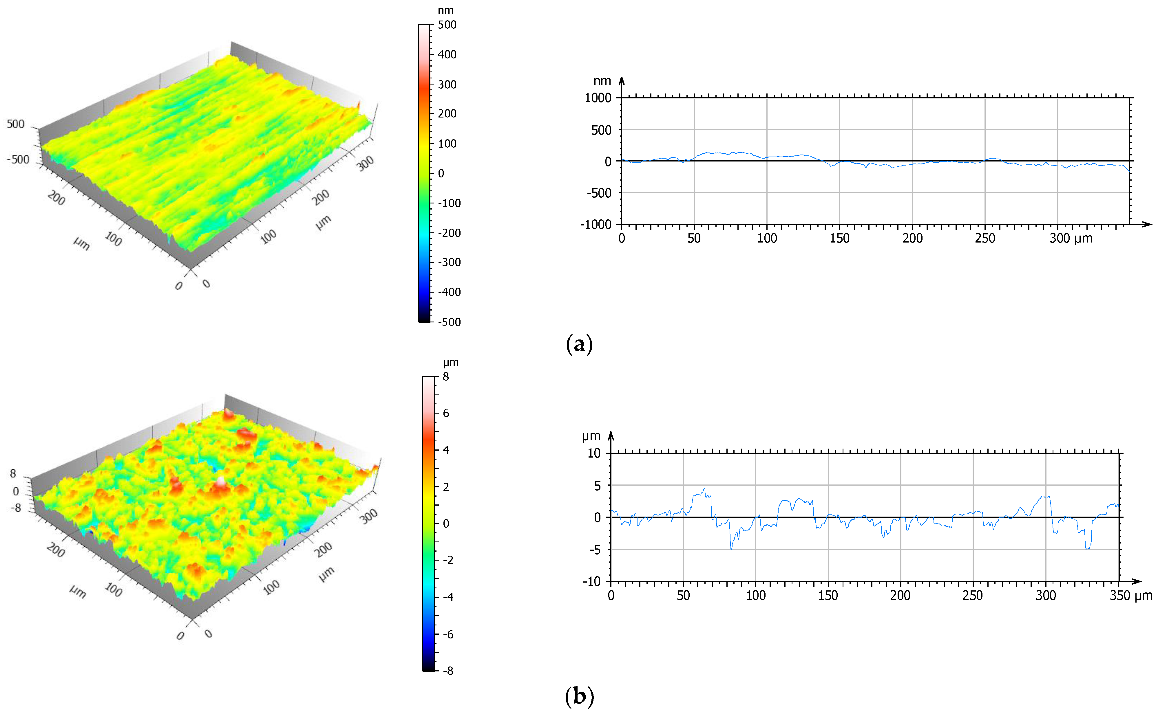
Surface topography analyses performed before tribological tests were based on 3D axonometric images, primary profiles, and amplitude parameters (Sa, arithmetic mean of the surface roughness deviation; Sp, maximum peak height; Sv, maximum indentation depth; Sku, surface peakness (kurtosis); Ssk, degree of symmetry (skewness)). The data presented in
Figure 12 and
Figure 13 and
Table 6 are a valuable source of information on the performance characteristics of the tested surfaces.
The results of the geometric structure of the surface indicated that the deposition of a diamond-like coating doped with silicon significantly affected the change in the roughness parameters of Ti13Nb13Zr titanium alloy, with the greatest differences observed for the sandblasted surface (Sv decreased by about 17% and Sp by 51%). Analysis of the results in
Table 6 showed that the polished a-C:H:Si had the lowest roughness, while sandblasted Ti13Nb13Zr had the highest. This indicated that the sandblasted surface had the highest peaks and deepest valleys of all the samples analyzed. Information on the nature of surface topography is also provided by skewness (Ssk) and kurtosis (Sku). The results indicated that the highest skewness of 0.26 was obtained for the sandblasted Ti13Nb13Zr surface, which indicated the presence of steep peaks with sharp tips on the surface of this sample. A 35% decrease in Ssk as a result of DLC coating deposition demonstrated the loss of peakness. A kurtosis value of three meant that the distribution of peaks and valleys on the surface was uniform and close to a normal distribution. This was the distribution we dealt with in the case of the polished Ti13Nb13Zr surface. A significant increase in Sku—up to 6.72 in the case of the Ti13Nb13Zr sandblasted sample—indicated that, as a result of the physical and chemical treatments applied, surface topography changed (an increase in the peaks and valleys on the Ti13Nb13Zr alloy). The topography of friction pair surfaces affected the value of the friction coefficient and wear rate. An accurate analysis of the geometric structure of the surface allowed a preliminary prediction of tribological properties already at the stage of surface layer formation.
3.5. Tribological Tests
The tribological properties of materials are critical for the proper operation of components. The purpose of this research was to determine tribological characteristics (coefficients of friction and linear wear) of the friction pairs studied.
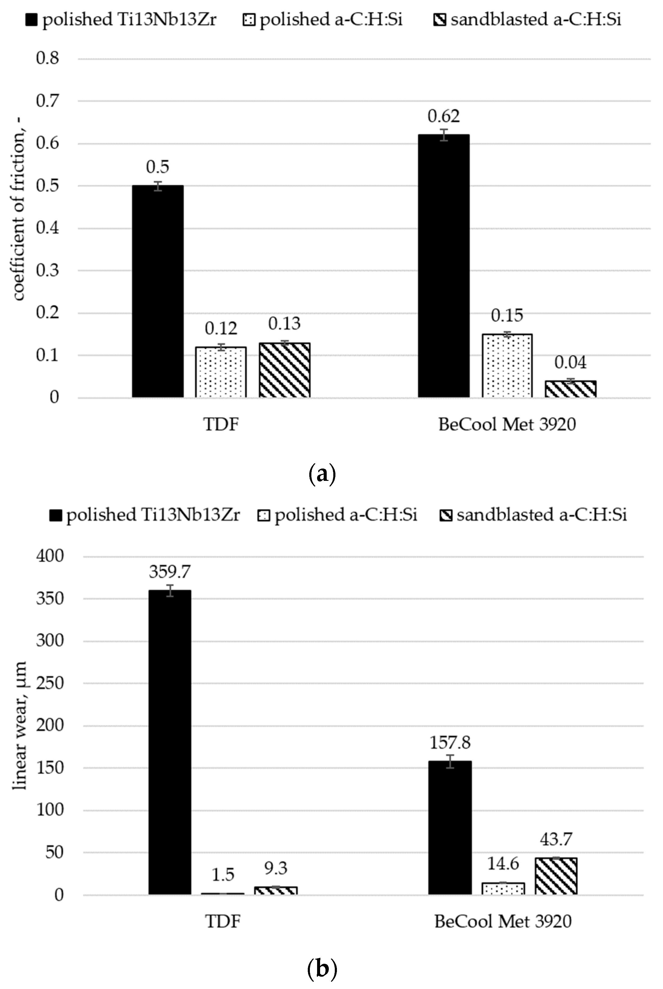
Figure 14 shows diagrams of average values of friction coefficients (a) and linear wear (b) for all the materials tested under dry friction and friction lubricated with BeCool Met 3920 coolant.
The results of the tribological tests indicated that the titanium alloy had the highest coefficients of friction and linear wear of all tested samples. Moreover, it was observed that the application of the lubricant simultaneously contributed to increasing the friction coefficient of the Ti13Nb13Zr-Al2O3 friction pair by about 20% and reducing its linear wear by more than 50%. Compared with the sandblasted sample, the a-C:H:Si coating deposited on the polished surface had lower coefficients of friction and linear wear under dry friction by about 10% and 83%, respectively. In contrast, due to the presence of depressions and elevations, the a-C:H:Si coating applied to the sandblasted sample was characterized by a longer run-in time and better lubrication of the friction node. This was evidenced by the recorded values of friction coefficients and linear wear during lubricated friction with BeCool Met 3920 coolant. Their values were 75% lower and 65% higher, respectively, compared with polished a-C:H:Si.
3.6. Assessment of Surface Geometric Structure of Samples and Counter Samples
After tribological tests, both the samples (
Figure 15 and
Figure 16) were subjected to microscopic observations. Optical and 3D axonometric images, abrasion profiles, and the maximum abrasion depth on the cross-section are presented in
Figure 17. The counter samples (
Figure 18 and
Figure 19) were also tested. The values of amplitude parameters are summarized in
Table 7 and
Table 8.
Table 9 and
Table 10 show the most important indicator of friction pair surface wear: the volume of abrasion.
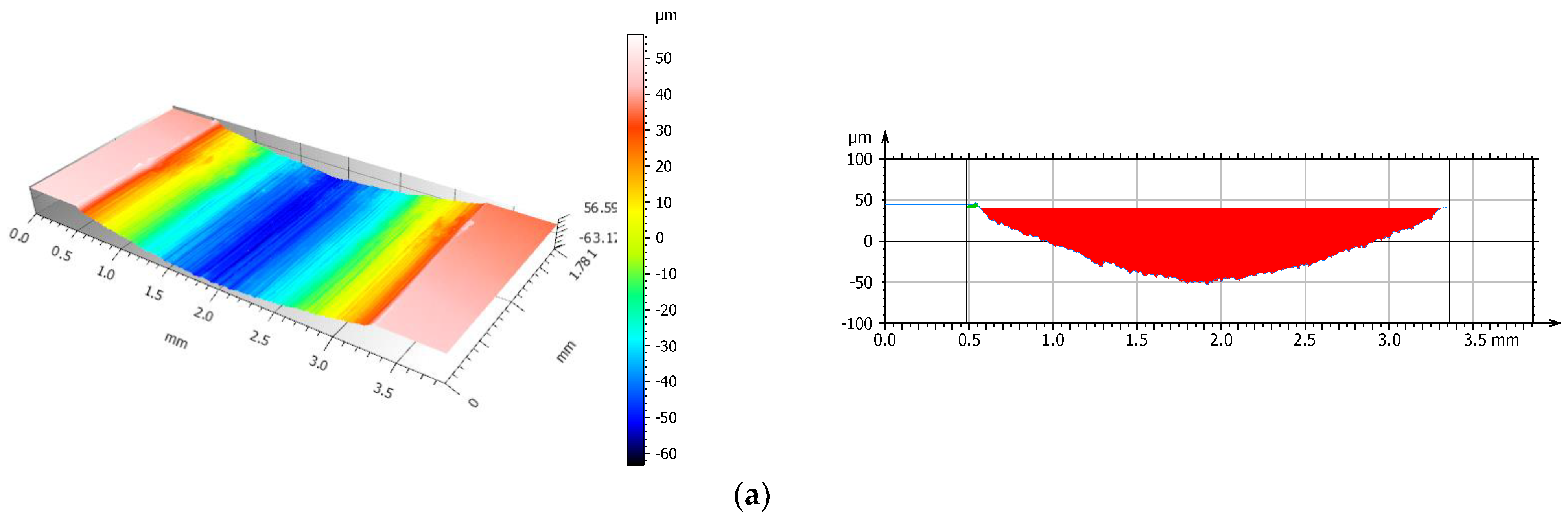
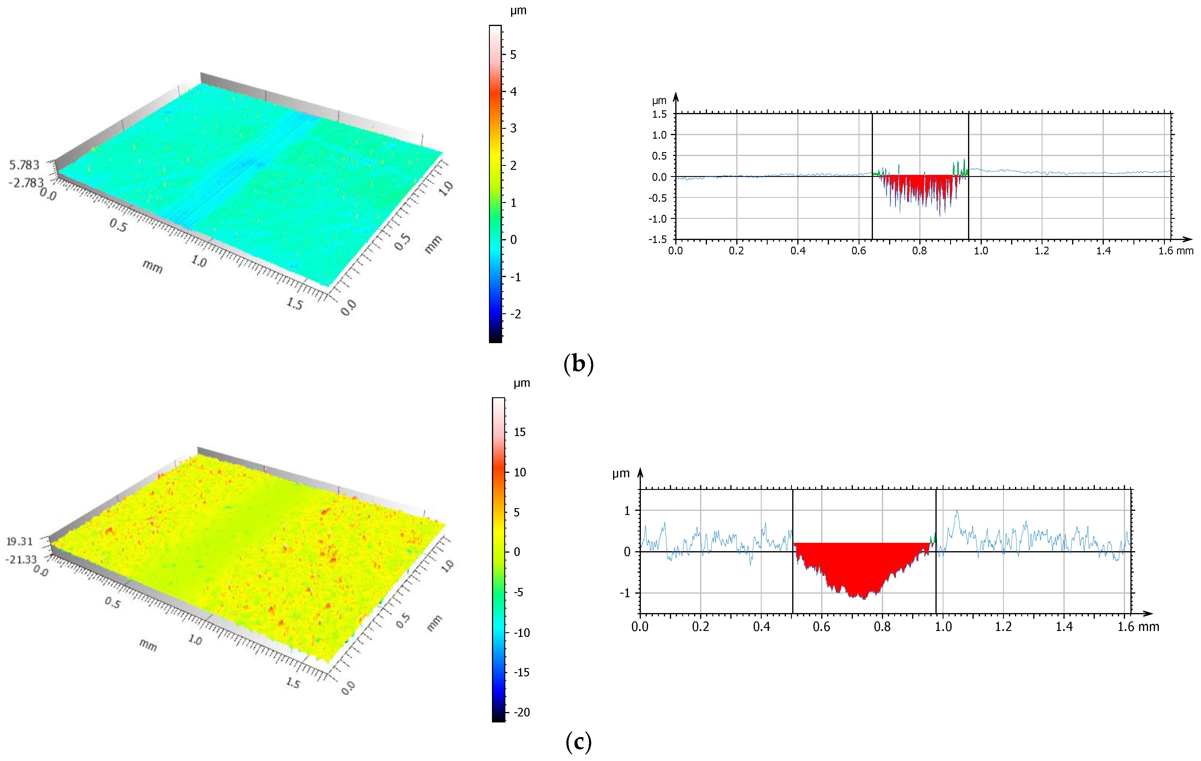
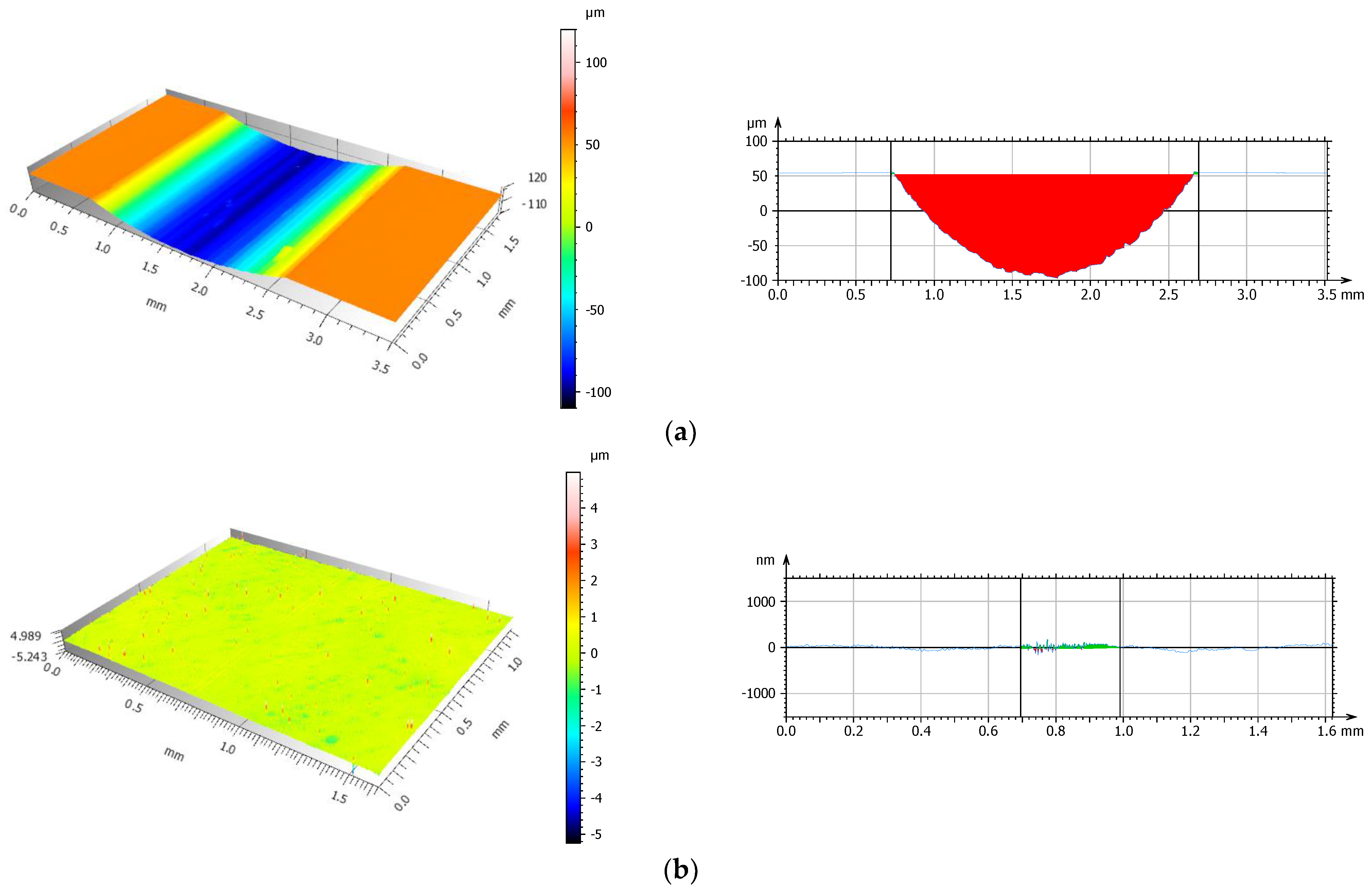
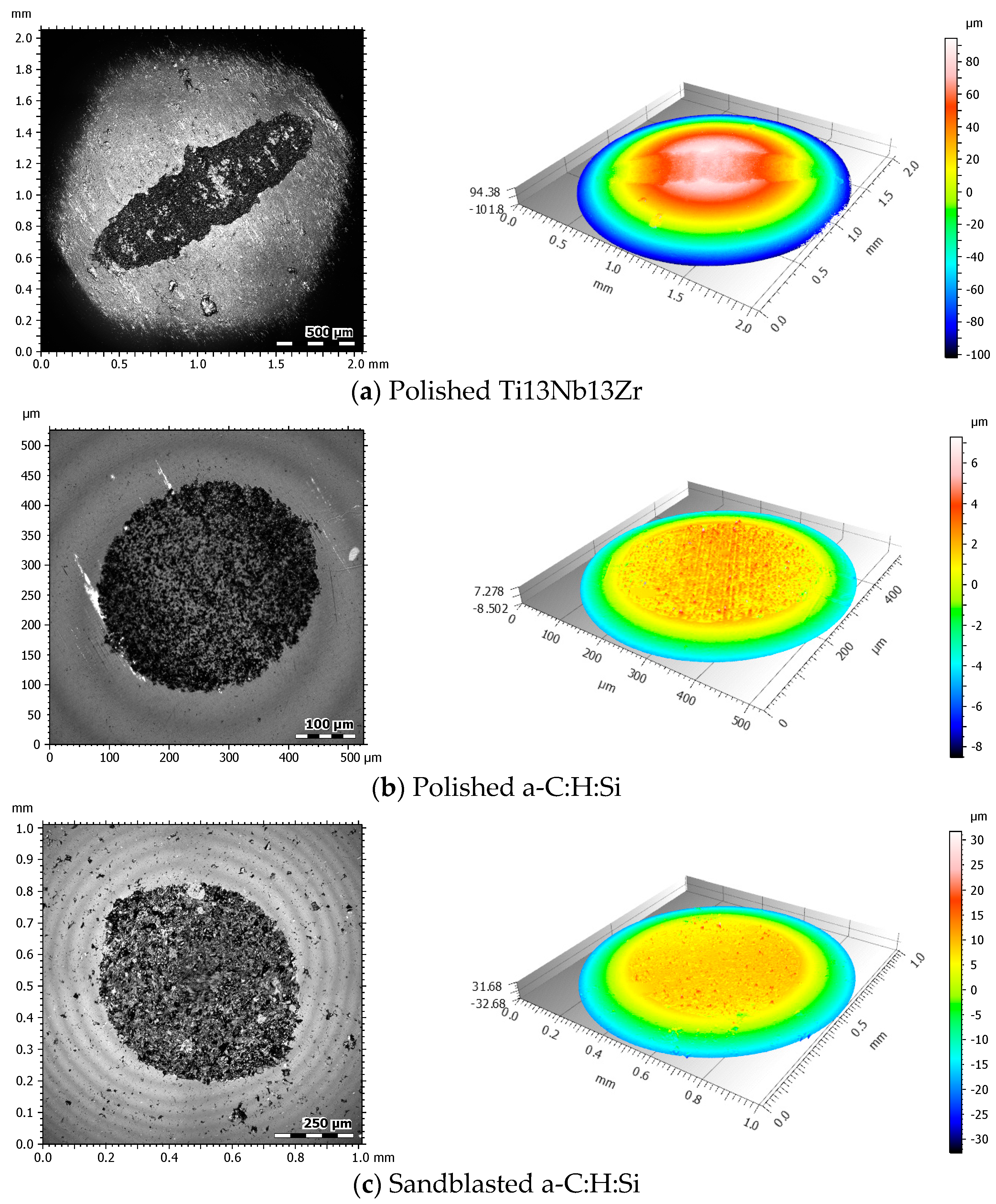
Figure 15.
Three-dimensional axonometric images and average values of abrasion profiles after friction in dry conditions: (a) polished Ti13Nb13Zr sample, (b) polished a-C:H:Si coating, and (c) sandblasted a-C:H:Si coating.
Figure 15.
Three-dimensional axonometric images and average values of abrasion profiles after friction in dry conditions: (a) polished Ti13Nb13Zr sample, (b) polished a-C:H:Si coating, and (c) sandblasted a-C:H:Si coating.
Figure 16.
Three-dimensional axonometric images and average values of abrasion profiles after lubricated friction with BeCool Met 3920: (a) polished Ti13Nb13Zr sample, (b) polished a-C:H:Si coating, and (c) sandblasted a-C:H:Si coating.
Figure 16.
Three-dimensional axonometric images and average values of abrasion profiles after lubricated friction with BeCool Met 3920: (a) polished Ti13Nb13Zr sample, (b) polished a-C:H:Si coating, and (c) sandblasted a-C:H:Si coating.
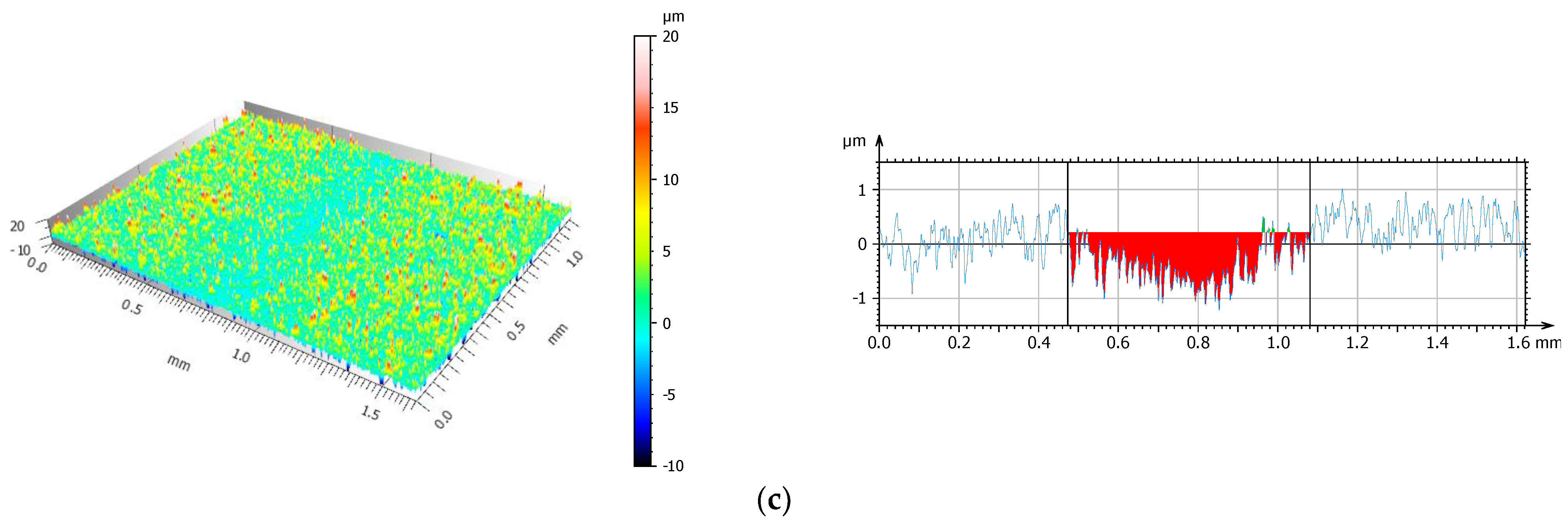
Figure 17.
Maximum depth of wear trace on a cross-section.
Figure 17.
Maximum depth of wear trace on a cross-section.
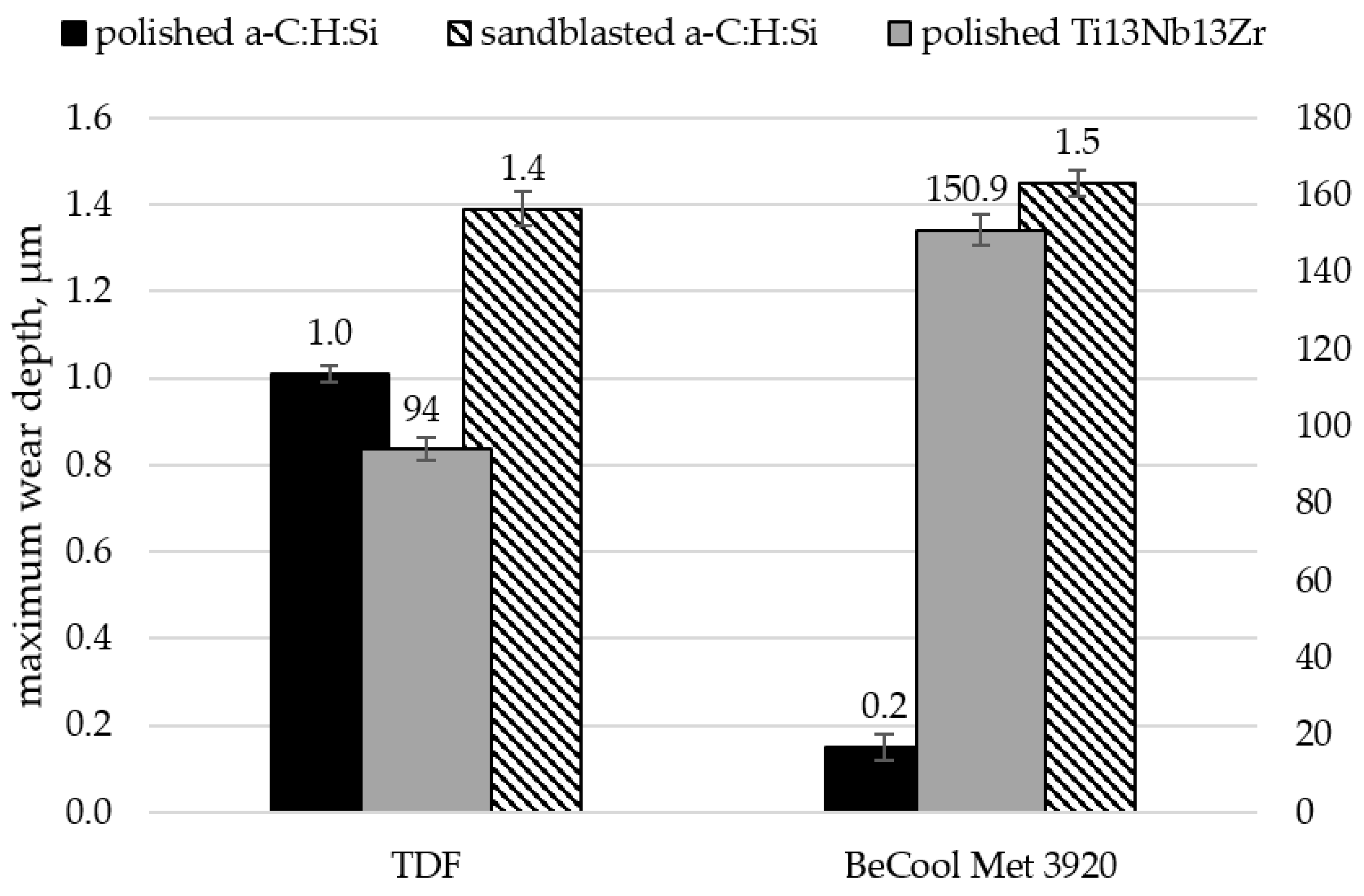
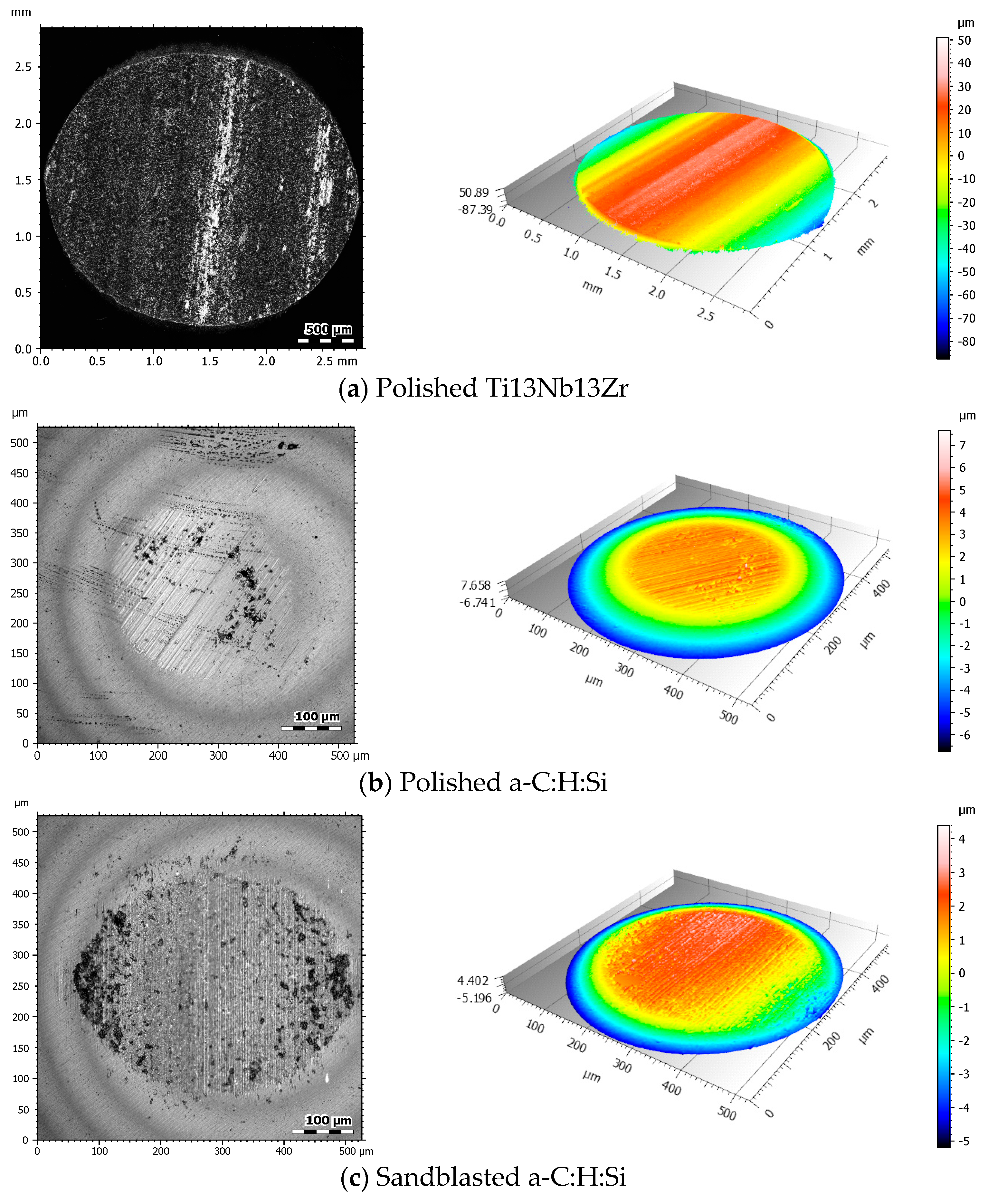
Figure 18.
Optical and 3D axonometric wear images of balls after dry friction (a) Polished Ti13Nb13Zr; (b) Polished a-C:H:Si; (c) Sandblasted a-C:H:Si.
Figure 18.
Optical and 3D axonometric wear images of balls after dry friction (a) Polished Ti13Nb13Zr; (b) Polished a-C:H:Si; (c) Sandblasted a-C:H:Si.
Table 7.
Amplitude parameters of the Ti13Nb13Zr alloy and coatings after friction in dry conditions.
Table 7.
Amplitude parameters of the Ti13Nb13Zr alloy and coatings after friction in dry conditions.
| | Ti13Nb13Zr | a-C:H:Si |
|---|
| Polished | Sandblasted | Polished | Sandblasted |
|---|
| Sa, µm | 1.13 | not measured | 0.24 | 0.18 |
| Sv, µm | 3.92 | not measured | 1.01 | 10.13 |
| Sp, µm | 5.89 | not measured | 0.97 | 4.59 |
| Ssk | −0.56 | not measured | −0.26 | −4.89 |
| Sku | 2.77 | not measured | 2.57 | 34.62 |
Figure 19.
Optical and 3D axonometric wear images of balls after lubricated friction with BeCool Met 3920.
Figure 19.
Optical and 3D axonometric wear images of balls after lubricated friction with BeCool Met 3920.
Table 8.
Amplitude parameters of the disc surface geometric structure after lubricated friction with BeCool Met 3920.
Table 8.
Amplitude parameters of the disc surface geometric structure after lubricated friction with BeCool Met 3920.
| | Ti13Nb13Zr | a-C:H:Si |
|---|
| Polished | Sandblasted | Polished | Sandblasted |
|---|
| Sa, µm | 4.78 | not measured | 0.15 | 1.2 |
| Sv, µm | 10.22 | not measured | 0.98 | 32.92 |
| Sp, µm | 14.16 | not measured | 3.83 | 26.80 |
| Ssk | 0.43 | not measured | 2.25 | −1.32 |
| Sku | 2.38 | not measured | 27.05 | 80.45 |
Table 9.
Wear volume.
| | Wear Volume, µm3 |
|---|
| | TDF | BeCool Met 3920 |
| polished Ti13Nb13Zr | 260 × 106 | 327 × 106 |
| sandblasted Ti13Nb13Zr | not measured | not measured |
| polished a-C:H:Si | 75 × 103 | 31 × 103 |
| sandblasted a-C:H:Si | 552 × 103 | 789 × 103 |
Table 10.
Ball wear volume.
Table 10.
Ball wear volume.
| | Wear Volume, µm3 |
|---|
| | TDF | BeCool Met 3920 |
| polished Ti13Nb13Zr | 211 × 106 | 54 × 106 |
| sandblasted Ti13Nb13Zr | not measured | not measured |
| polished a-C:H:Si | 35 × 103 | 84 × 103 |
| sandblasted a-C:H:Si | 222 × 103 | 546 × 103 |
The results of microscopic observations after tribological tests indicated that the values of amplitude parameters changed depending on the analyzed surface and friction conditions. These changes were indicative of a decrease or increase in the wear trace roughness. The greatest heights and valleys were observed in the sandblasted sample with the a-C:H:Si coating in dry conditions and with BeCool Met 3920 coolant lubrication. Analysis of 3D axonometric images found that the dominant wear mechanism on Ti13Nb13Zr was tribochemical wear through oxidation and abrasive wear with plowing effect and microcutting. The strong affinity of titanium for oxygen caused the formation of a thin passive layer composed of TiO2 on the surface of the Ti13Nb13Z alloy. As a result of friction, this layer cracked and crumbled, leading to intensive wear. Additionally, this process was intensified by the presence of loose wear products in the friction contact. Different wear mechanisms occurred during friction with the coatings. Abrasive wear by scratching and microcutting predominated, and asperities on the coating deposited on the sandblasted surface were sheared.
The results of the wear trace depth test showed that carbon coatings deposited on Ti13Nb13Zr were characterized by high wear resistance, with the best efficiency achieved on the polished surface. The lowest values were recorded for the polished surface under dry and lubricated friction with BeCool Met 3920. In the case of the coating deposited on the sandblasted specimen, the results from both friction conditions were comparable. Comparison of the values of the maximum wear depths to the coating thickness (
Section 3.2) found that the deposited layers performed very well in terms of their functional characteristics throughout the tribological tests. None of the layers was fully consumed.
The results of the wear trace and volume tests supported the conclusion about the low wear resistance of the titanium alloy and were consistent with the results reported in
Section 3.5. The coating deposited on the polished surface had the highest wear resistance, with the best antiwear efficiency obtained with BeCool Met 3920 lubrication. This indicated that this surface interacted well with the proposed lubricant. Compared with the a-C:H:Si on the polished surface, the wear of the a-C:H:Si coating deposited on the sandblasted surface was higher under dry and lubricated friction by 85 and 96%, respectively.
The highest wear of the counter samples (balls) was recorded for the interaction with the Ti13Nb13Zr alloy. In addition, it was observed that the use of a lubricant reduced the ball wear by about 75%. In the case of a-C:H:Si-Al2O3 friction junctions, the volume of counter sample wear increased as a result of the application of BeCool Met 3920 by about 41% for the polished surface and 60% for the sandblasted sample.
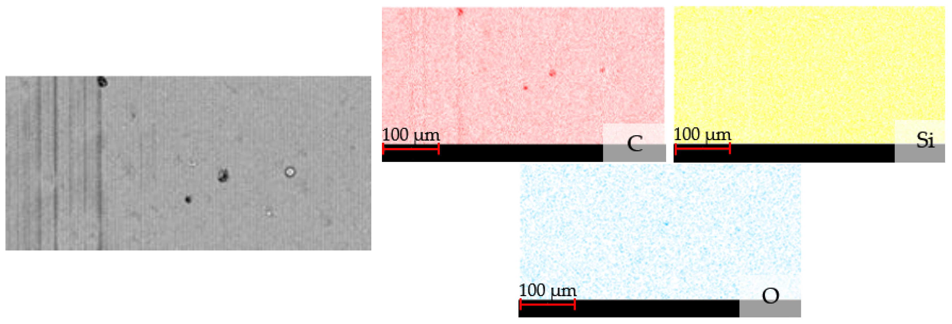
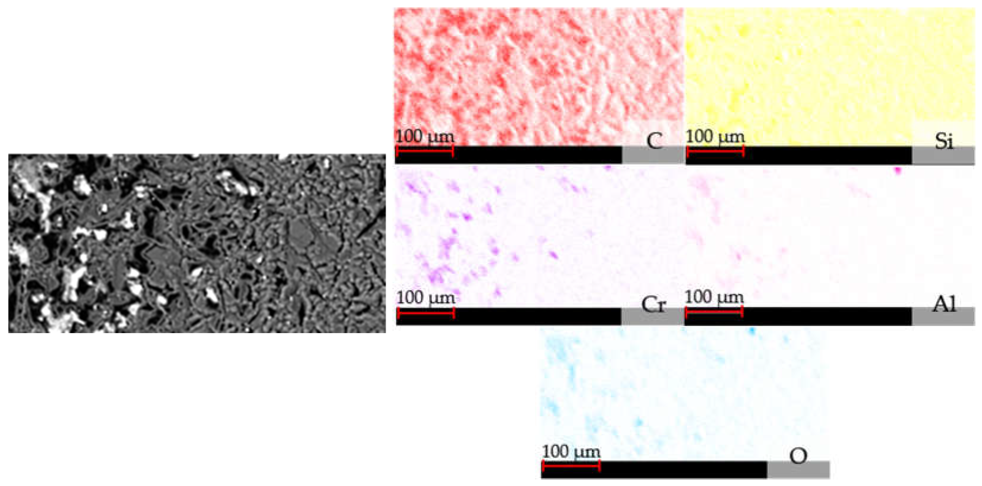
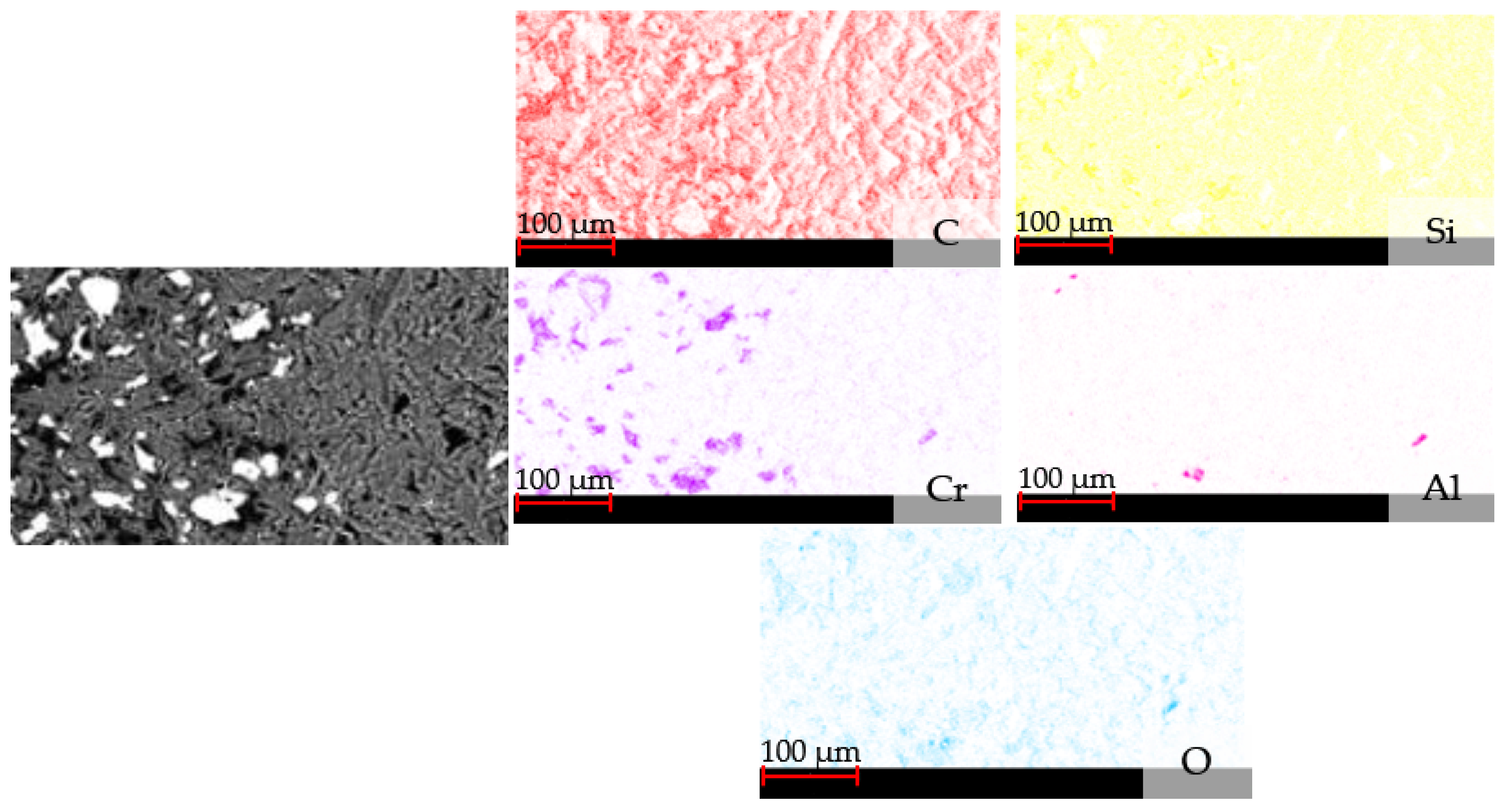
3.7. EDS Analysis of the Wear Trace after Tribological Tests
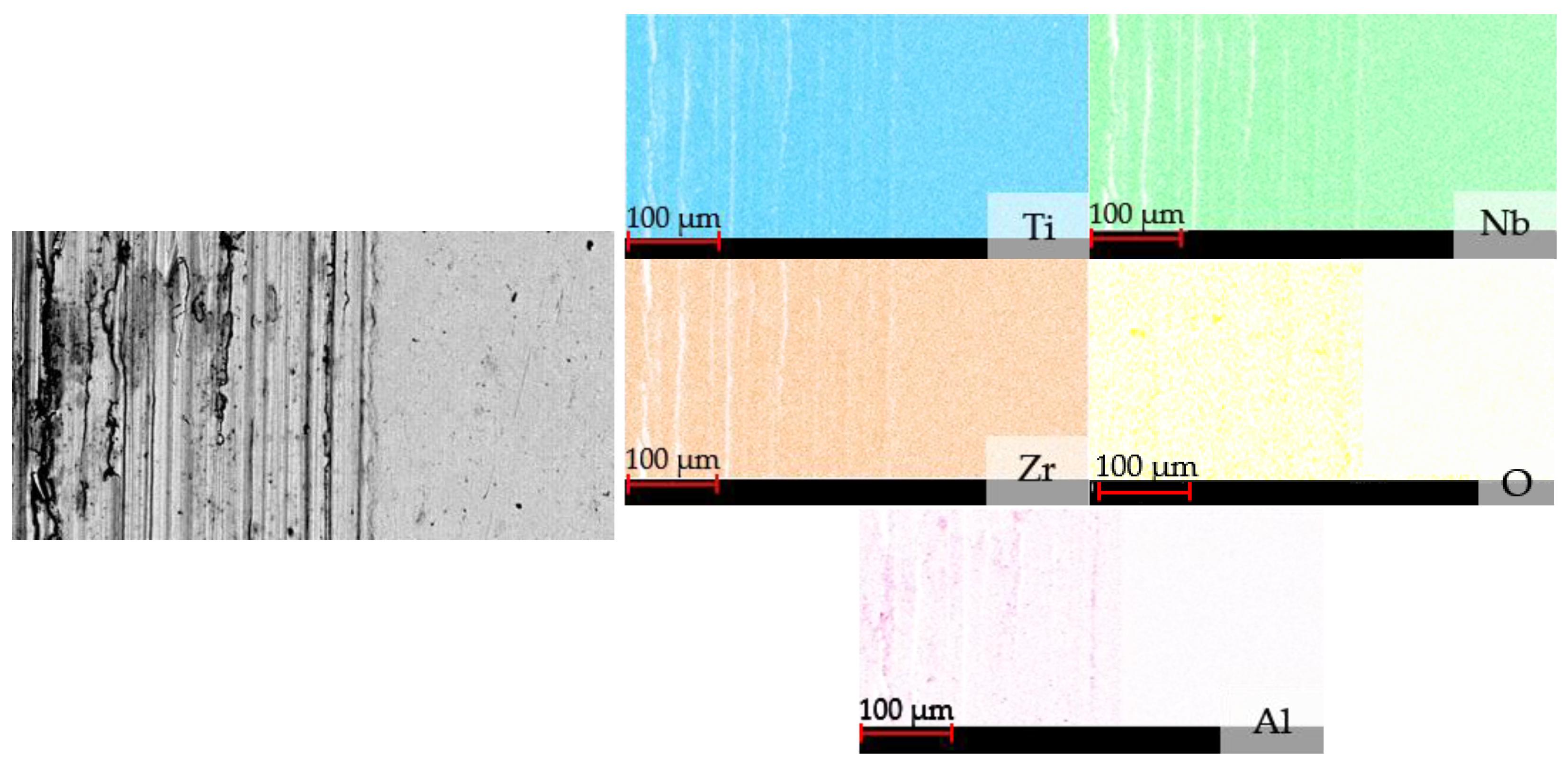
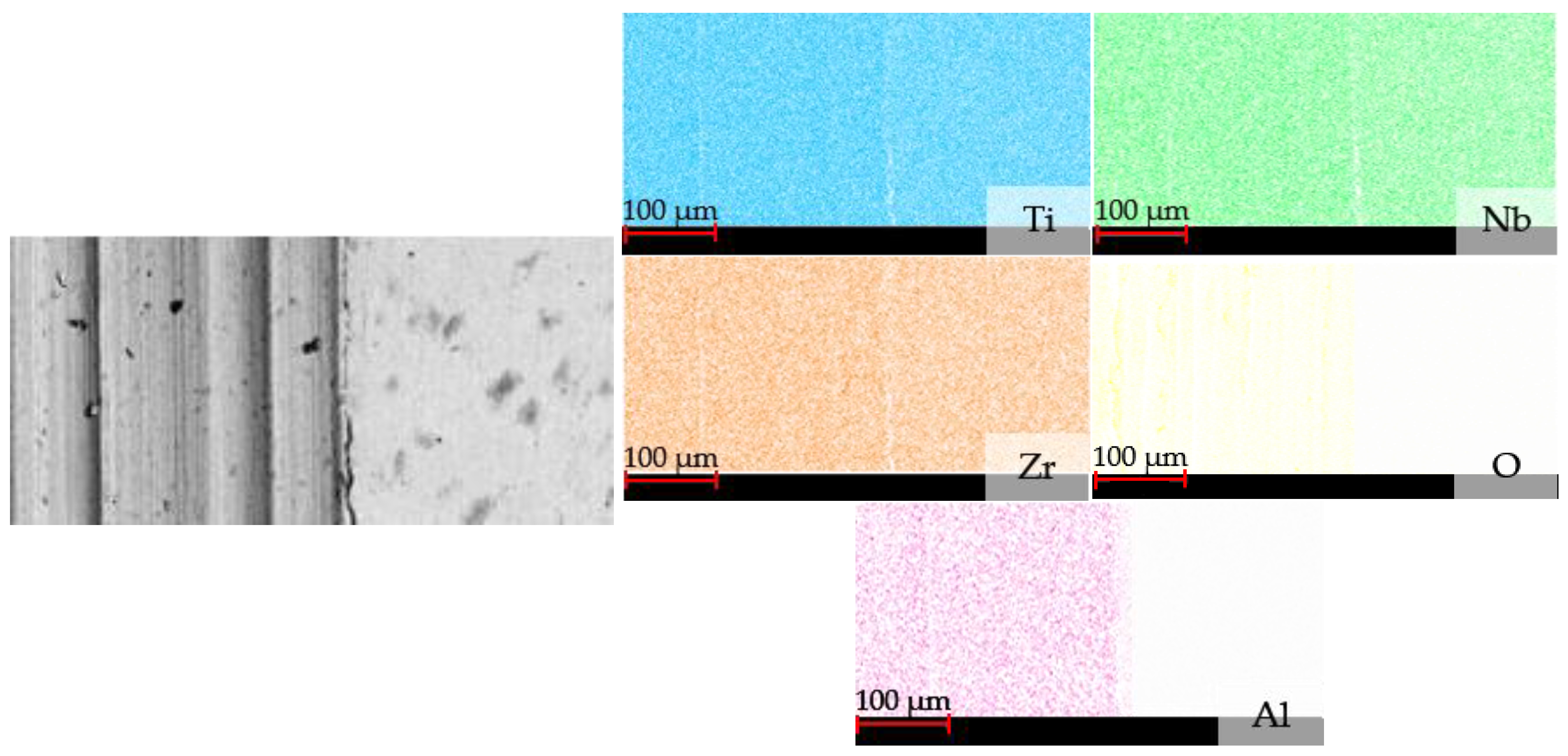
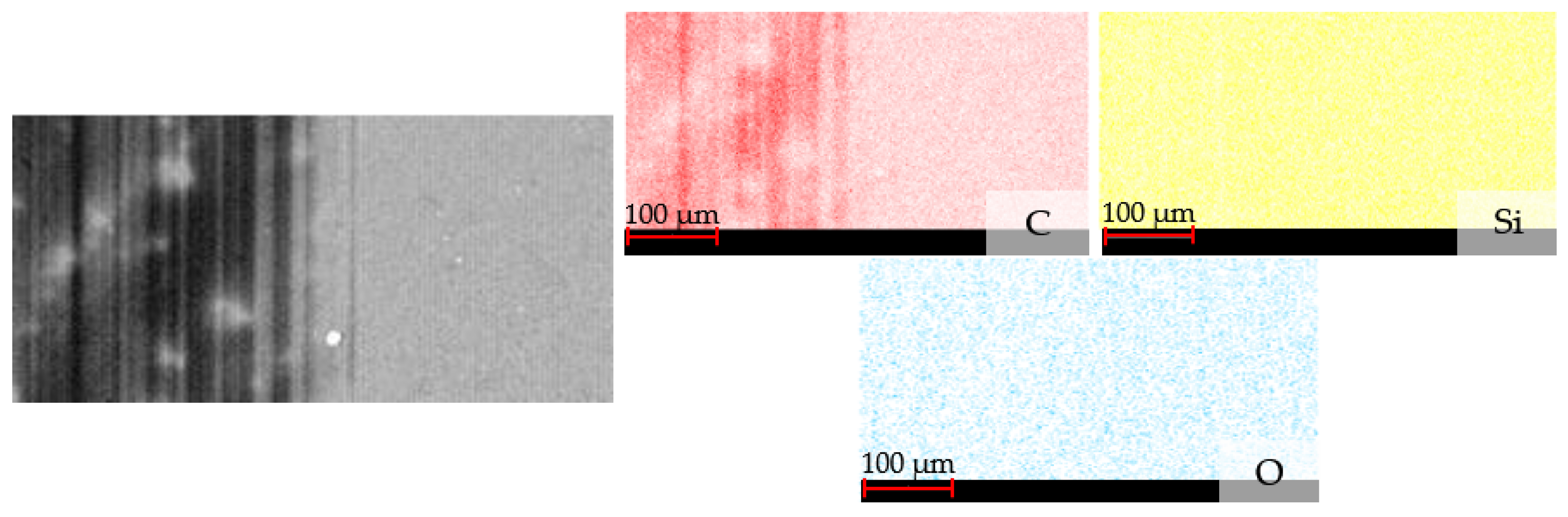
Due to limitations resulting from the too small measuring area of the scanning microscope and the inability to present the entire wear trace,
Figure 20,
Figure 21,
Figure 22,
Figure 23,
Figure 24 and
Figure 25 show maps of elemental distribution from part of the wear trace and the frictionless surface. The aim was to demonstrate differences in the distribution of individual elements on surfaces with and without friction.
The maps of the wear trace elemental distribution for Ti13Nb13Zr alloy after dry friction revealed the highest concentration of titanium and its even distribution over the entire area. In the case of niobium and zirconium, similar density and color intensity were observed, which indicated a similar percentage of these elements in the Ti13Nb13Zr alloy. Analysis in the friction area indicated the presence of oxygen and aluminum with a much lower degree of color saturation than in the case of titanium, niobium, and zirconium. Higher concentrations of these elements were found inside the abrasion trace than outside of it. The presence of aluminum resulted from the transfer of the counter sample material (the Al2O3 ball). A similar concentration of these elements was observed in the wear traces of the Ti13Nb13Zr alloy after friction with BeCool Met 3920 lubrication. In the case of a-C:H:Si coatings deposited on a polished surface, carbon and silicon dominated. A small concentration of oxygen was also observed both inside and outside the wear trace, and no aluminum was detected. EDS analysis of coatings applied to sandblasted surfaces indicated the highest percentages of carbon and silicon. Additionally, the chrome interlayer was exposed due to friction. Aluminum from the counter sample and oxygen were also detected in the abrasion traces, indicating surface oxidation of the sandblasted coating as a result of friction.


