Article

Using an Interlayer to Toughen Flexible Colorless Polyimide-Based Cover Windows

1
DuPont, Wilmington, DE 19803, USA
2
DuPont, Marlborough, MA 01752, USA
3
Materials Research & Design, Inc., Wayne, PA 19087, USA
*
Authors to whom correspondence should be addressed.
Coatings 2023, 13(9), 1597; https://doi.org/10.3390/coatings13091597
Submission received: 28 July 2023 / Revised: 24 August 2023 / Accepted: 7 September 2023 / Published: 13 September 2023
(This article belongs to the Special Issue Polymer Films/Membranes: Structure, Properties, and Applications)

Abstract

:
Colorless polyimide (PI)-based flexible cover windows are a critical component of flexible electronics to protect devices from unwanted chemical and mechanical damage. The integration of flexible colorless PI-based windows into electronics applications is limited by the embrittlement of some colorless PI films when they are coated with hard coats. Here, we investigate the embrittlement mechanism of hard-coated colorless PI films and the role of interlayers in toughening the colorless PI-based cover windows for flexible electronics applications. A fracture mechanics approach combined with finite element analysis (FEA) models is employed to compute fracture strain, εc, for different crack cases in the bilayer (hard coated colorless PI) and trilayer (with an additional interlayer) cover windows. For the model inputs and validation, the material properties of the cover windows are characterized. We show that the embrittlement is attributed to the fracture behavior of the cover windows, and placing a ductile interlayer increases the εc of colorless PI films. Using the fracture analysis as a design guide, we fabricate a trilayer cover window with an acrylic thermoset interlayer and demonstrate an improvement of the εc of the colorless PI cover window by ~42%. We believe our analysis provides insights into design guides for mechanically robust cover windows using colorless PI films and flexible HCs for emerging flexible electronics.

1. Introduction

The flexible electronic device industry has experienced tremendous growth since the introduction of foldable smartphones in late 2018 [1,2]. Despite their popularity, the market for flexible devices is still in its early stages and limited to high-end products due largely to the complex design and manufacturing challenges. One of the most challenging parts of design is flexible cover windows, which must be bendable to a tight radius while still offering protection against mechanical and chemical damage [3,4]. These requirements cannot be met by traditional cover glass windows.
For flexible cover windows, striking a balance between flexibility and mechanical robustness has been enabled by recent technological advancement in thin glasses and colorless polyimide (PI) films [5,6,7,8]. While both materials have been used in flexible devices, thin glasses are too fragile for use as the outermost layer of the devices without additional protective layers [9]. On the other hand, colorless polyimide (PI) films offer more flexibility and toughness than thin glasses, but they are much softer and therefore require a polymeric flexible hard coat (HC) layer to improve their mechanical robustness. By carefully engineering PI-based bilayer cover windows, it is possible to achieve a well-balanced combination of flexibility and mechanical robustness for better protecting flexible electronic devices [3].
The integration of PI-based bilayer cover windows into flexible electronics is limited by the susceptibility of some colorless PI films to embrittlement in the presence of the HC layer. It has been reported that [10] while standalone colorless PI films exhibited ~20% strain at break, εb, the same films coated with a flexible HC underwent a dramatic decrease in εb to as low as ~2% with increasing HC thickness up to 35 μm. As the fracture strain of brittle coatings on polymer substrates typically decreases with increasing coating thickness [8,9], this embrittlement is likely attributed to the fracture behavior of the bilayer cover window instead of a chemical interaction [11,12]. Understanding mechanisms for the embrittlement is crucial to achieving reliable colorless PI-based cover windows.
If the embrittlement of the colorless PI films is a fracture problem, one possible solution is incorporating a ductile interlayer for toughening. There have been reports [13,14] that depositing ductile organic layers between inorganic brittle barrier films toughened the barrier films and its fracture strain increased. However, to our knowledge, the role of the interlayers in the fracture of polymeric substrates has not been studied, and the embrittlement mechanism is still unclear.
Here, we investigate the embrittlement mechanism of hard coated colorless PI films and the role of interlayers in toughening the colorless PI-based cover windows for flexible electronics applications. We first describe a fracture mechanics model for bilayer and trilayer cover windows with different crack configurations. Next, for model inputs and validations, the material properties of the cover window layers are characterized. Then, critical strain to failure, εc, is computed by utilizing finite element analysis (FEA) for a wide variety of cover windows with different crack configurations and varying material properties and interlayer thickness. By plotting the computed εc as a function of the representative elastic property, we show that the embrittlement is attributed to the fracture behavior of the cover windows and placing a ductile interlayer toughens the cover windows. To validate our work, we incorporated an acrylic thermoset interlayer to fabricate a trilayer cover window that exhibited improved εc.

2. Fracture Model, Materials, and Methods
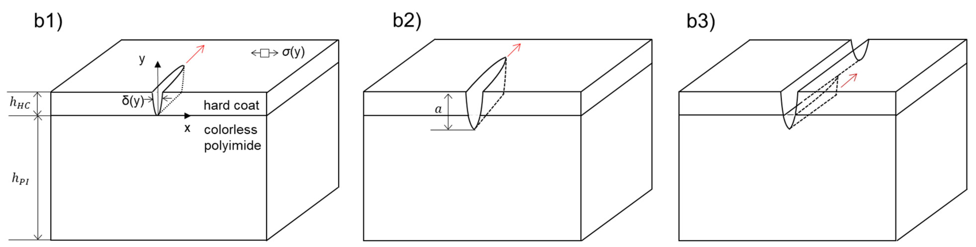
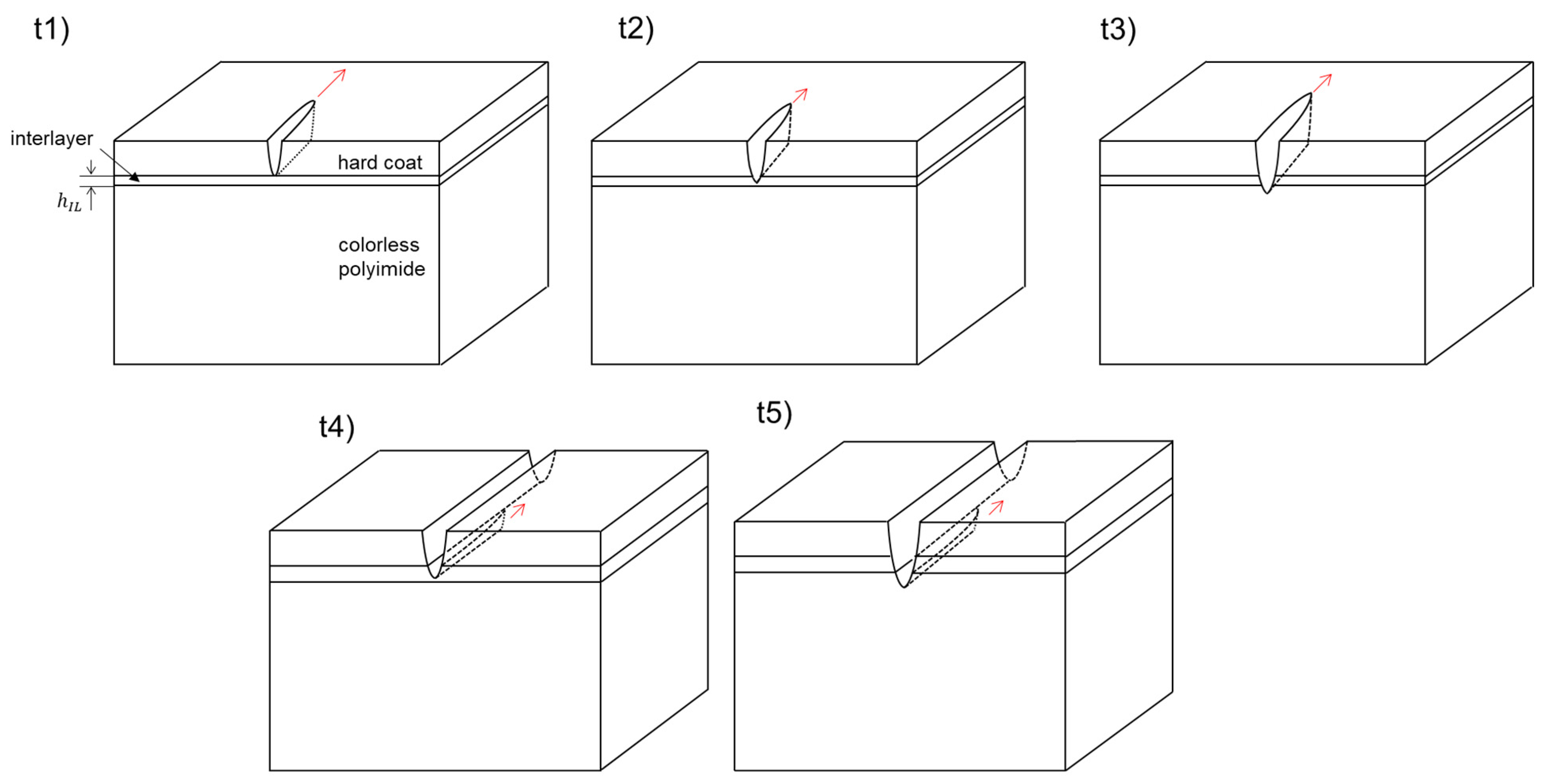
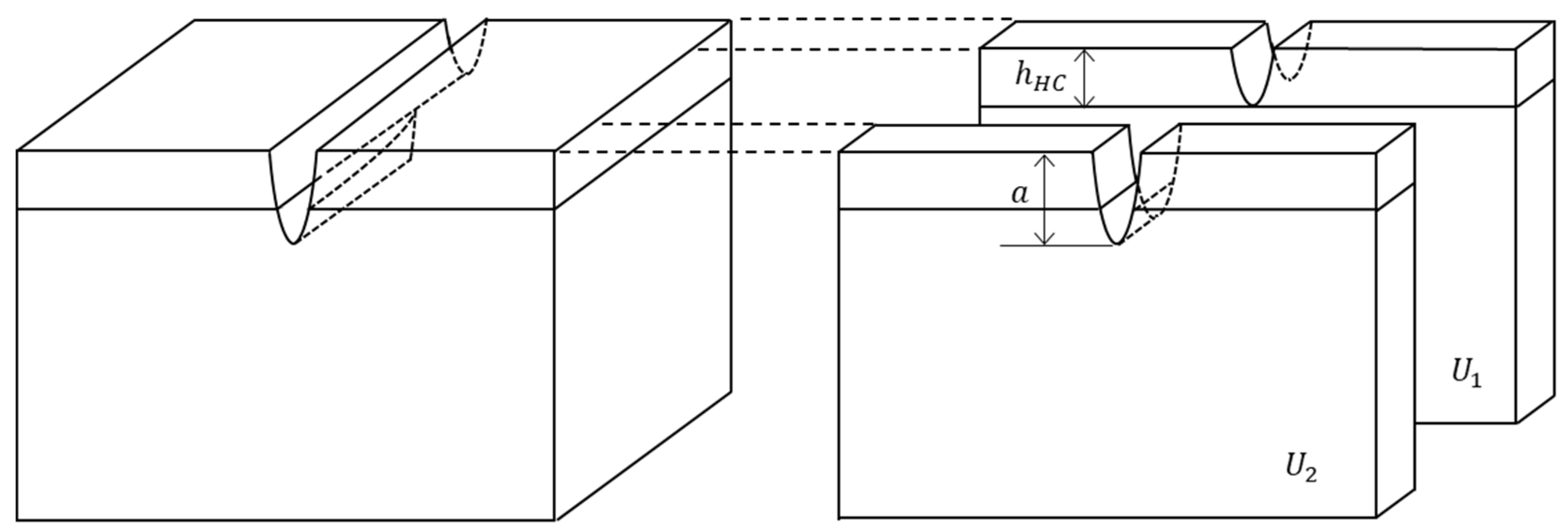
The embrittlement of hard-coated colorless PI films is hypothesized to be a fracture-driven problem. Like other brittle coatings on polymer substrates [15,16], a channel crack first forms and propagates in the brittle HC layer under tensile loading. Then, another channel crack forms in the colorless PI-film due to a stress concentration leading to catastrophic failure of the cover window at εc < εb. Note that by convention, the failure strain of materials without defects in tension is typically denoted by εb, and that of materials in the presence of cracks is denoted by εc.
In this section, we first describe a fracture mechanics model and the FEA methods to compute the εc of different crack configurations for bilayer and trilayer PI-based cover windows. Then, we describe the materials and experimental characterization techniques used for the bilayer and trilayer cover windows as well as their fabrication methods.

2.1. Fracture Model

Our fracture model is based upon the existing models for thin bilayer films on stiffer substrates subjected to residual stresses [17] (substrates have little stress) and the previously described multilayered barrier coatings on more compliant substrates subjected to uniform tensile loading [13,14] (both the coating and substrates have stress). Our model is an extension of the previous works but includes the analysis of substrate fracture in the presence of an interlayer under uniform tensile loading. Linear elasticity and linear elastic fracture mechanics (LEFM) are assumed.
We consider a total of eight possible crack cases for the bilayer and the trilayer cover windows. The crack cases for the bilayer cover window are illustrated in Figure 1(b1–b3). For simplification, only a single crack is considered in each case. Case b1 is a channel (i.e., propagating) crack in the HC layer only; case b2 is a channel crack propagating through the HC layer and a part of the colorless PI substrate; and case b3 is a channel crack in the colorless PI substrate under a fully propagated crack across the HC layer.
The crack cases for the trilayer cover windows are illustrated in Figure 2(t1–t5). Case t1 is a channel crack in the HC layer only; case t2 is a channel crack in both the HC layer and the interlayer; case t3 is a channel crack through the HC layer, the interlayer, and a part of the colorless PI substrate; case t4 is a channel crack in the interlayer under an already propagated crack in the HC layer; and case t5 is a channel crack in the colorless PI substrate under an already propagated crack across the HC layer and the interlayer.
To compute εc for these crack cases, crack driving force is calculated based on refs. [13,14,17]. The crack driving force is also called strain energy release rate, G, which is equivalent to a reduction in elastic energy by a crack formation [18] relieving stresses in the cover windows. For cases b1, b2, t1, t2, and t3, the G may be obtained by [13,14,17]:
G = 1 2 a 0 a σ y δ y d y
where a is the crack length, σ y is the stress far ahead of the crack front, and δ y is the crack opening displacement far behind the crack front as illustrated in Figure 1(b1). σ y is assumed uniform within each layer and is calculated by the well-known Hooke’s law:
σ y = E ( y ) 1 ν ( y ) 2 ε
where E and ν are the modulus and the Poisson’s ratio of each layer, respectively, and ε is the strain. The computed G can then be normalized by the elastic properties of the HC layer as [14,17]
G = E H C 1 ν H C 2 h H C ε 2 Z = E H C * h H C ε 2 Z .
where E H C * is the plane strain modulus of the HC layer [19], and Z is the dimensionless parameter depending only on the crack geometry and the material properties of the cover window [13,14,20]. For cases b1 and t1, a channel crack in the HC layer propagates when the G in Equation (3) is equal to or exceeds the fracture energy of the HC layer, G c H C which is given by
E H C * h H C ε c 2 Z = G c H C
Thus, the normalized εc is given by
ε c G c H C / h H C E H C * = 1 Z b 1   o r   t 1             ( c a s e s   b 1   a n d   t 1 )
εc can be obtained by characterizing Z using FEA and the material properties of the HC layer.
For other channel crack cases, the normalized εc can also be computed by relating the G to the appropriate Gc
ε c G c H C / h H C E H C * h H C + h P I ( G c P I / G c H C ) a Z b 2                                           ( case   b 2 ) = h H C + ( a h H C ) ( G C I L / G C H C ) a Z t 2                               ( case   t 2 ) h H C + h I L ( G c I L / G c H C ) + ( a h I L h H C ) ( G c P I / G c H C ) a Z t 3               c a s e   t 3 .
where hPI and hIL are the thickness, and G c P I and G c I L are the fracture energy (Gc) of the colorless PI substrate and the interlayer, respectively. For cases b2, t2, and t3, where channel cracks propagate in more than one layer, Gc is estimated by the rule of mixture.
For a channel crack propagating under a fully propagated crack (cases b3, t4, and t5), G can be characterized by traditional J-integral [21,22] to compute G for a plane strain crack as a function of crack length a, i.e., G(a) [17]. Note that the plane strain crack is a fully propagated crack across the cover window and propagates to the depth direction. Then, G for case b3 is obtained by integrating G(a) from the interface (bottom of the HC layer) to a [17]:
G = 1 a h H C h H C a G a d a
However, computing G(a′) requires different FEA geometries for each crack length. J-integral also encounters convergence issues at the interface [17,23]. Alternatively, we propose using Equation (1) to compute G for those crack cases. The method does not require separate FEA models for different crack lengths and is free from the convergence issues. Taking case b3 as an example (Figure 3), similar to case b1 the G is equivalent to a reduction in the elastic energy by a channel crack formation under a fully propagated HC crack. This energy reduction can be computed by subtracting elastic energy in a unit thickness of the cover window far ahead of the advancing channel crack (U1) from that far behind of the crack front (U2). U is equal to G (Equation (1)) multiplied by a, so the G for case b3 may be given by
G = 1 a h H C a G 2 h H C G 1
The denominator in this equation accounts for the depth of the channel crack. Assuming the reduction in stress by a fully opened crack is negligible as reported previously [17], G2 and G1 in Equation (8) are equivalent to those of case b2 and b1, respectively. In the Supplementary Document, we show that G from the proposed method is almost identical to that from the traditional J-Integral method. Now, using Equation (8), the normalized εc for the crack cases b3, b4, and b5 can be calculated altogether:
ε c G c H C / h H C E H C * = G c P I / G c H C Z b 3 , t 5                         c a s e   b 3   a n d   t 5                                                 = G c I L / G c H C Z t 4                                                     c a s e   t 4 .

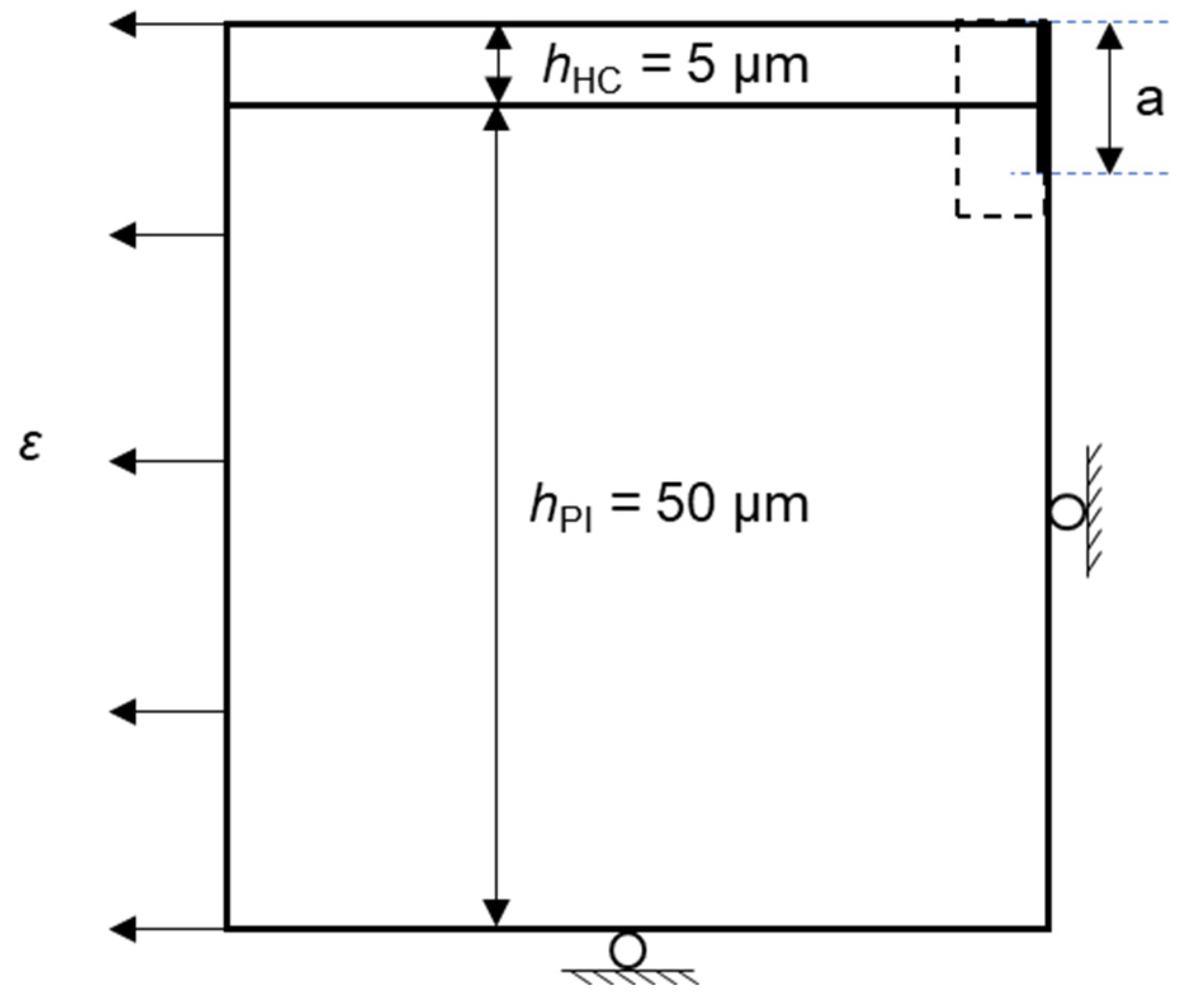
2.2. Finite Element Analysis

The commercial finite element software, ABAQUS (2019), was used to characterize the dimensionless function, Z, for the crack cases with varying coating thickness and materials properties. Figure 4 shows the geometry and boundary conditions for a bilayer cover window used for FEA. The thickness of the HC layer and the clear PI substrate was fixed at 5 μm and 50 μm, respectively; the thickness of the interlayer was varied from 0.5 μm to 5 μm; and the crack length, a, was varied from 5 to 10 μm. The elastic modulus was varied for the three layers as listed in Table 1. Differences in elastic properties between the HC layer and the colorless PI substrate were quantified by so-called Dundur’s parameter, α [17,24]:
α = E H C E P I E H C + E P I
The parameter is often used to understand the fracture properties of multi-layered structures [12,17]. The calculated α values for our FEA models are listed in Table 1. The Poisson’s ratio was fixed at 0.34 for the clear PI substrate, 0.3 for the HC layer, and 0.35 for the interlayer.
The model geometry consisted of the crack region (inside the dotted rectangle) and the peripherical region, both of which were joined using a tie constraint in Abaqus. Note that we performed a mesh convergence study and ran several cases without a tie constraint to confirm it did not affect the results quantities of interest. The discretization of the geometry in the crack region (inside the dotted rectangle in Figure 4) was much more refined compared to the peripherical region. No boundary condition was applied to the right side of the crack region, and roller boundary conditions were applied to the bottom and left sides of the periphery of the crack tip. The model without the interlayer had ~240,000 bilinear plane strain quadrilateral (CPE4) elements with 4 nodes. A uniform lateral displacement field corresponding to 2% strain was applied to the left side of the geometry. The residual strain was assumed zero in the FEA model. The FEA model used for J-integral is detailed in the Supplementary Document.

2.3. Materials

A UV curable urethane acrylate-based flexible HC [3,25] was used to fabricate bilayer and trilayer cover windows. A waterborne thermoset acrylic polymer (Rhoplex 3208 from Dow Inc., Midland, MI, USA) was used as the interlayer to demonstrate its effectiveness as a crack stop layer. The solid loading of the acrylic polymer was varied to as high as 18.6% in solution.
A colorless PI film was used as the substrate. The polymer backbone was developed using a strategy to achieve low color by disrupting intrachain and interchain charge transfer transitions which would otherwise introduce color. In addition, the synthetic and film-forming process was optimized for improved optical and mechanical performance. High modulus and low color can be achieved simultaneously through the choice of monomers, polymer backbone chemistry, and process conditions. The material properties and performance of the colorless polyimide films used in the study are listed in Table S1 Supplementary Materials (also see [3] for more details).
To characterize the material properties, the HC layer and the interlayer were coated on both 6” Si wafers and polymer films by a spin-coater (model WS650-23, Laurell Technologies, Lansdale, PA, USA) and a bar coating at room temperature. The casted HC formulation was UV-cured using a Fusion 300 conveyor system (irradiance ~1600 mW/cm2). Each film passed the UV lamp three times at 50 feet/minute. The average energy density values were around 450, 150, 40, and 500 mJ/cm2 in the UVA, UVB, UVC, and UVV regimes, respectively. The casted interlayer was thermally cured in two steps at 120 °C for 5 min for initial drying and at 150 °C for 10 min for the full cure. It should be noted that the curing processes did not cause the embrittlement of the colorless PI films.

2.4. Cover Window Fabrication

To fabricate bilayer cover windows, the HC formulation was deposited on the colorless PI substrate using a slot die coater. Then, the HC layer was cured by the previously described processes. To fabricate trilayer cover windows, the interlayer formulation was first deposited on the colorless PI substrate via Gravure coating. The line speed was controlled at 5 ft/min to achieve the optimal heating time. The colorless PI substrate was subsequently corona treated. After flashing off the water, the acrylic polymer was thermally cured at 120 °C for 5 min and subsequently at 150 °C for 10 min. The varying film thickness was achieved by diluting the dispersion with deionized water (6 to 18% solid loading). Finally, the HC layer was deposited using the slot die coater.

2.5. Nanoindentation

Hysitron TriboIndenter TI980TM with nanoDMA® III (Bruker, Minneapolis, MN, USA) was used to obtain the elastic modulus E of the HC and the interlayer on Si wafers. The nanoindenter was operated in CMX mode [26], in which the indenter tip was continuously oscillated at ~1 nm amplitude. A Berkovich tip was used and calibrated by indenting a fused quartz standard sample at depth between 100 and 350 nm. Test specimens were glued to sample holders using a hot melt adhesive (CrystalbondTM 555, Aremco Products, Valley Cottage, NY, USA). Nine indentations were made on each specimen. Subsequently, 4 indentations were made on the fused silica to verify the area function calibration.

2.6. Tensile Test

Tensile test was performed to measure the elastic properties of the colorless PI films and the ε c of the cover windows. The thickness of the colorless PI substrate and the HC layer was 50 and 5 μm, respectively. The test specimens were 12.7 mm wide and 50 mm long in gage length, and were pulled at the rate of 6 mm/min. The strain was measured by an optical extensometer or digital image correlation [27]. The onset of a channel crack was detected by a camera. The test was repeated 5 times.

2.7. Fracture Test

To characterize the Gc of the HC layer and the interlayer, a bilayer fracture test [11,28,29,30] was utilized. Bilayer tensile specimens were fabricated by coating the 30 μm HC layer and the 30 μm interlayer on 250 μm PET substrates. Testing 5 specimens for each condition, the bilayer films were pulled at 6 mm/min until a channel crack was detected by an optical camera to characterize the εc. Because the configuration of the test specimens with a channel crack is identical to case 2b (Figure 1), by using Equation (4) and measured εc values it is possible to characterize the Gc of the HC layer and the interlayer. The Z values for the HC layer and the interlayer were computed by the FEA method using the measured modulus of the PET substrate and the HC layer (Table 2). The computed Z values for the HC layer and the interlayer were 2.0 and 1.9, respectively (Table S2 in Supplementary Materials). Note that the HC layer and the interlayer were coated much thicker than those in the cover windows to fracture each layer at strain within its elastic limit. Residual strain was ignored as it is small compared to the fracture strain. For the colorless PI substrate, the Gc value was estimated due to a difficulty of characterizing plane strain fracture property for polymer films [31,32,33].

3. Results and Discussion

3.1. Embrittlement of Colorless PI Film

The tensile tests were performed on the standalone colorless PI films and the hard coated cover windows with α = 0.063 (Figure 5). The standalone colorless PI films exhibited εb at 27%. The same PI films coated with the 5 μm HC layer exhibited final failures at at εc = 8.3% after the HC channel cracking formation at εc = 5.0%. Additionally, the embrittlement of the colorless PI films was demonstrated in bending. The out-fold bending (the HC layer was in tension in bending) of the same bilayer cover window fractured into two pieces (Supplementary Video S1) while the same bending did not lead to the fracture of the standalone colorless PI films (Supplementary Video S2). We note that the colorless PI films did not show any embrittlement after exposure to the solvent used for the HC casting and the subsequent thermal and UV curing processes.

3.2. Materials Characterization

The measured elastic and fracture properties of the materials are listed in Table 2. The Gc of the HC layer, G c H C , exhibited a larger variation, which is attributed to variations in flaw size due to the large coating thickness. Nonetheless, the characterized G c H C was 100 J/m2, which is significantly greater than those of typical inorganic silicate barrier coatings [28]. The Gc value of the interlayer, G c I L , was a conservative estimate. In the fracture test, even the 50 μm thick interlayer did not fail at 3.9%, well above the elastic limit of typical thermosets, and this strain value results in a G c I L equal to 810 J/m2.

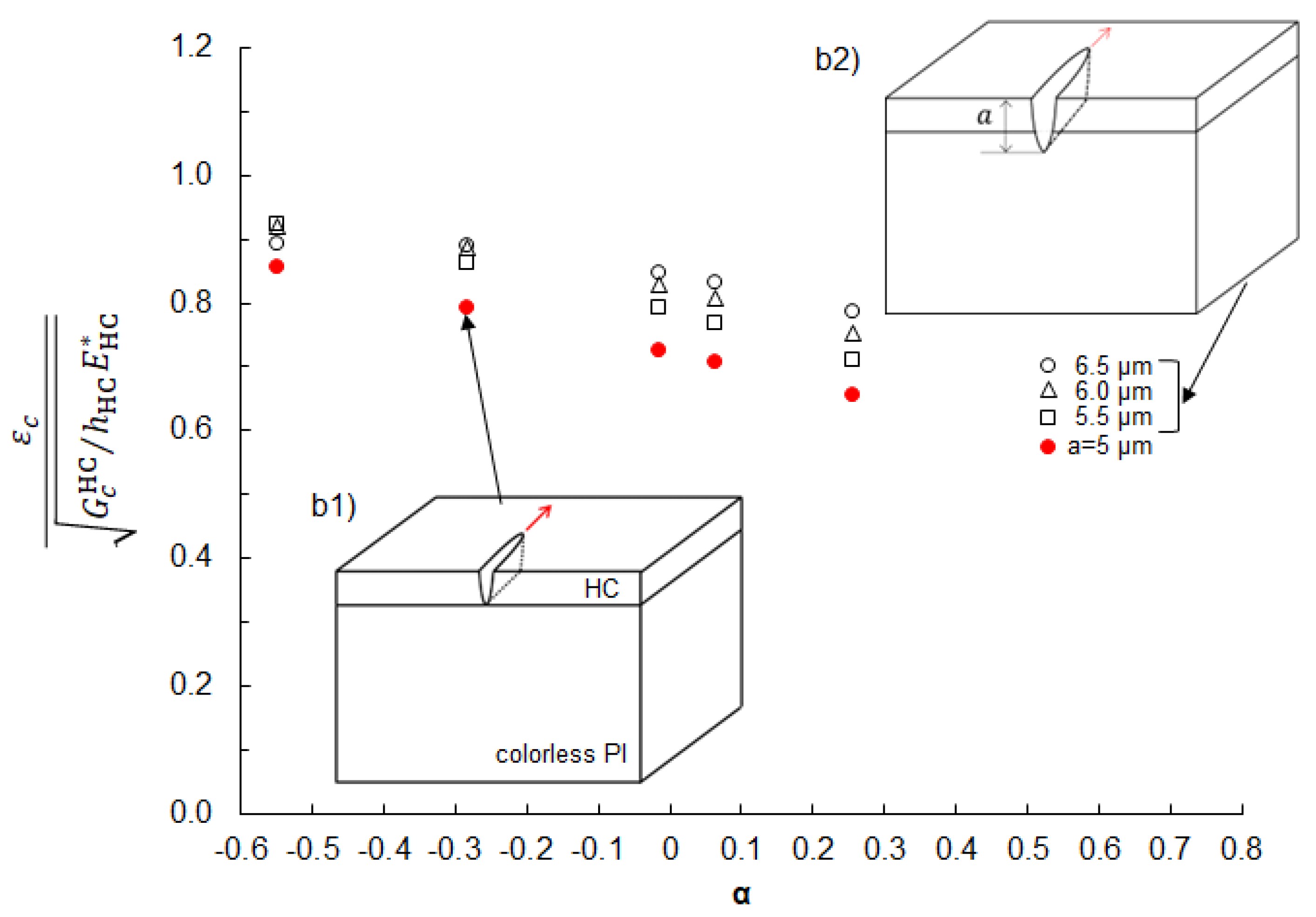
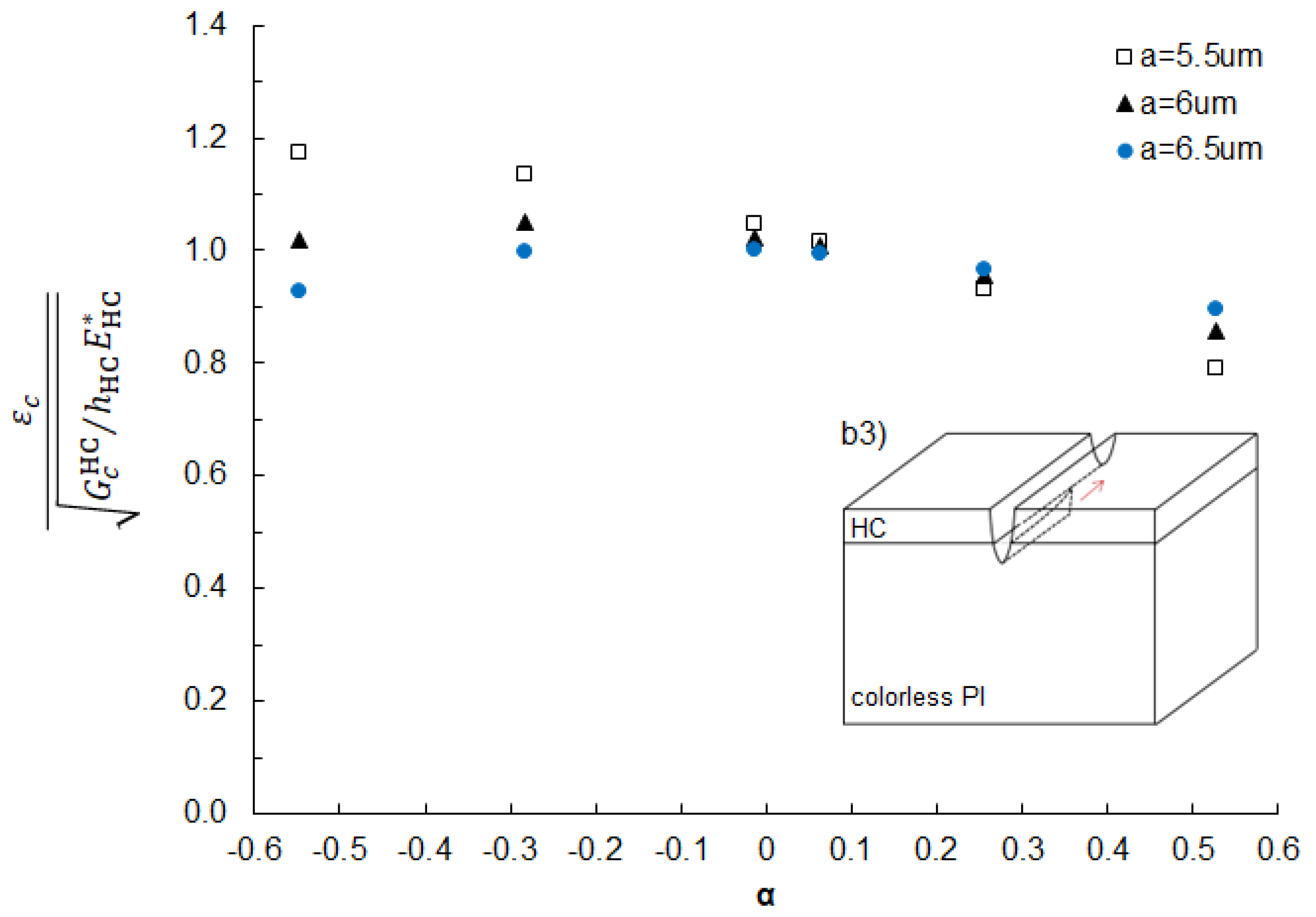
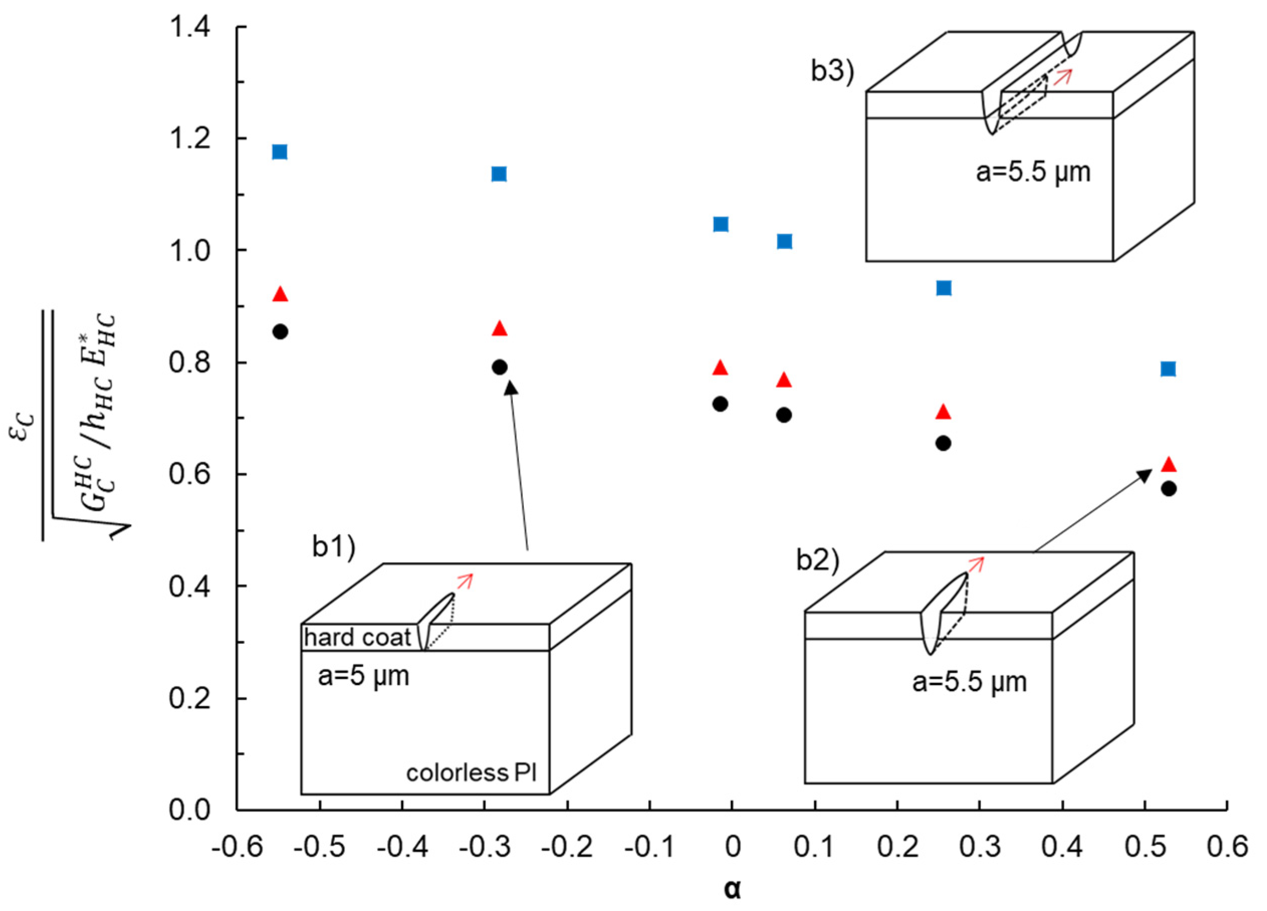
3.3. Fracture Analysis

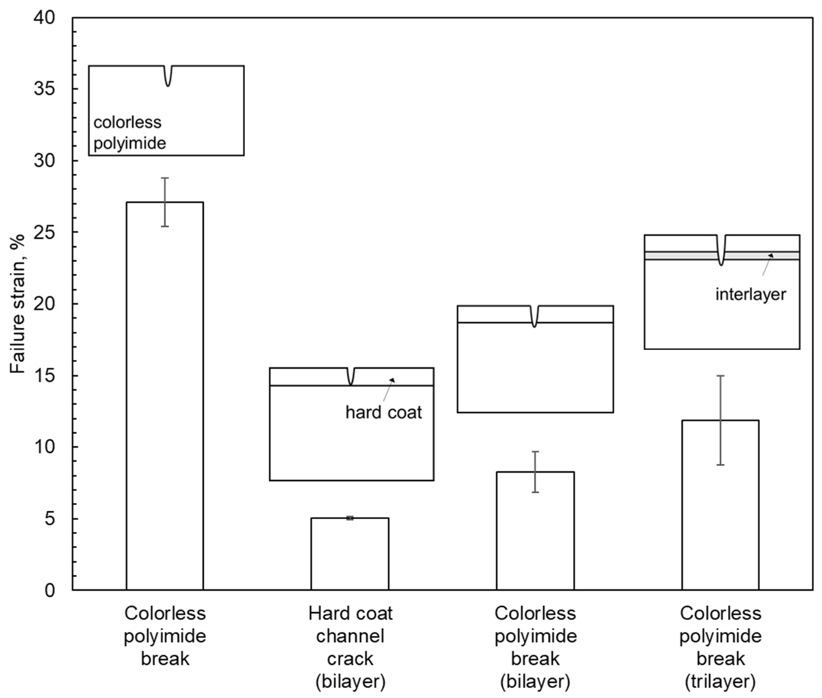
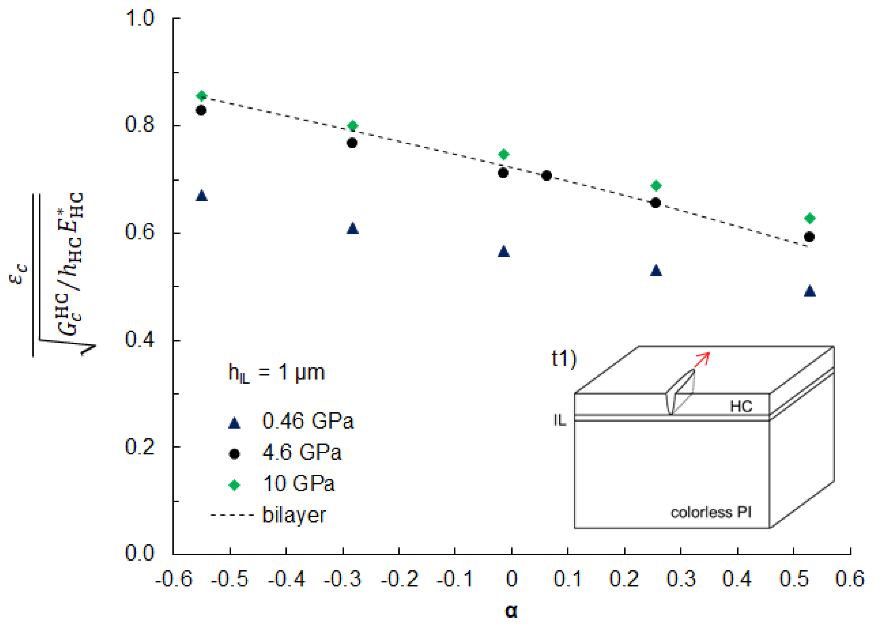
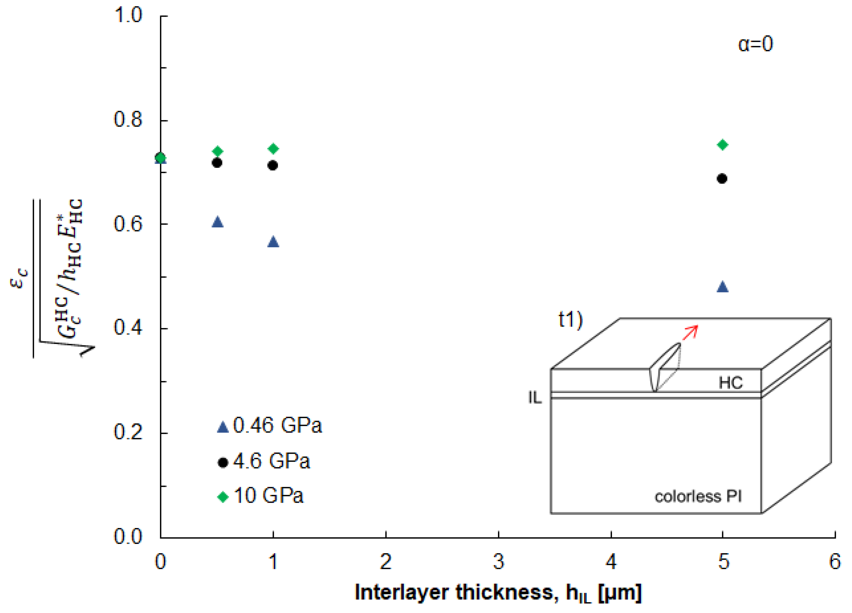
3.3.1. Bilayer Cover Window

The normalized εc of a channel crack through the HC layer in the bilayer cover windows (case b1) is shown as a function of α in Figure 6. The normalized ε c decreases with increasing α. Stiffer colorless PI substrates (lower α) can constrain the crack opening in the HC layer more than compliant colorless PI substrates (higher α). This indicates that cover windows with lower α values (i.e., soft top layer on hard substrate) are more resistant against cracking in the HC layer. However, such cover windows are not practical at this point, as soft layers are more susceptible to unwanted mechanical damage such as scratching and denting and soft and self-healing protective sheets [34,35,36] are still in a research stage.
For a channel crack propagating through the HC layer and a part of the colorless PI substrate (case b2), the normalized ε c is plotted as a function of α for selected a in Figure 6. Like case b1, the normalized ε c decreased with increasing α. The trend is also explained by the degree of constraint from the colorless PI substrates. At the same α, the normalized ε c , increased with increasing a as G c P I > G c H C and the contribution from the colorless PI substrate to the total Gc increased with increasing a. It is noted that the normalized ε c values for case b2 are higher than those for case b1 at the same α, indicating that case b2 cannot occur in the bilayer cover windows.
Figure 7 shows the normalized ε c for case b3 as a function of α for selected a values. The normalized ε c was computed by the proposed method and Equation (8). To validate the method, selected crack cases were also computed by the traditional J-integral and Equation (7). The two methods were found to generate almost identical results (Figures S1–S3 in Supplementary Materials). When a = 5.5 μm, the normalized ε c decreased monotonically with increasing α like cases b1 and b2. When a = 6 and 6.5 μm, the normalized ε c exhibited a concave downward trend with increasing α. It is interesting to note that when α values ≥ 0.256, the normalized ε c increased with increasing a, which is opposite to the typical fracture behavior of monolithic materials and means that the channel crack would stop propagating to the thickness direction under the same stress. This is associated with the loading condition and the elastic mismatch. In our study, the bilayer cover windows were uniformly stretched, so ε was uniform throughout the cover window. However, the stress values change across the interface due to the modulus difference, except for α = 0 (Equation (2)). In the cover windows with higher α ( E H C > E P I ), stress in the colorless PI substrate is lower than that in the HC layer, leading to a decrease in G when the crack penetrates deeper into the substrate. This analysis suggests that increasing E H C is beneficial to mitigating the cracking of the PI substrate or the final failure of the bilayer cover windows. It is noted that when α values ≤ 0.063, the trend reversed and the normalized ε c decreased with increasing a, indicating a spontaneous (unstable) crack propagation once a channel crack is nucleated in the colorless PI. The cover windows showed that the embrittlement had α = 0.063, which is indeed consistent with the analysis.
It is instructive to compare the normalized ε c for the three bilayer cases in Figure 8 to understand the failure mechanism of the bilayer cover windows. Note that the crack case with the lowest normalized ε c is the energetically favored failure mechanism. A channel crack in the HC layer (case b1) has the lowest ε c values across α, so this is the first failure mode to happen and is consistent with the tensile test results (Figure 5) and bending test (Supplementary Videos). Once case b1 occurs, case b2 is no longer a feasible failure mode. However, case b3 can occur when the bilayer cover windows are subjected to additional tensile strain equivalent to the difference in normalized ε c between case b1 and case b3. For the cover window with α = 0.063, the difference in normalized ε c between case b1 and case b3 corresponds to 2% strain, which is matched well with the measured difference in ε c (3.3%) for the bilayer cover windows in the tensile test (Figure 5).

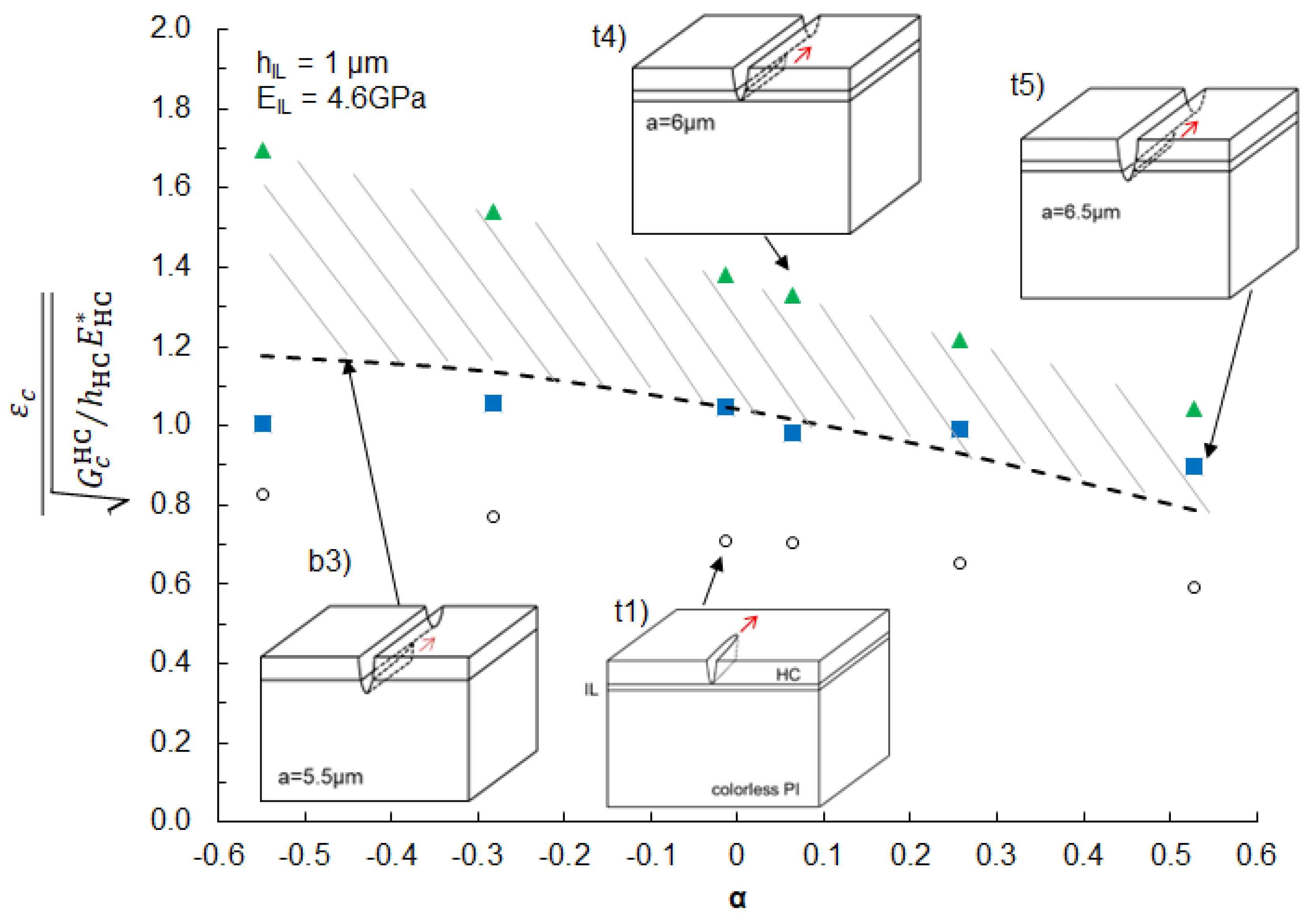
3.3.2. Trilayer Cover Window

We analyzed the failure mechanisms of trilayer cover windows with an interlayer. Based on the analysis in the previous section, a channel crack propagation in both the HC layer and the interlayer is less likely to occur, so the analysis for cases t2 and t3 are provided in Supplementary Materials (Tables S3–S5).
The normalized ε c for case t1 is shown as a function of α between the HC layer and the colorless PI substrates (Figure 9). The interlayer was 1 μm thick and had varying EIL from 0.46 GPa to 10 GPa. For comparison, the analysis for case b1 is plotted with a dashed line. While the trend of the normalized ε c with α is similar to that of case b1, the normalized εc values for case t1 are lower than those for case b1, except for the trilayer cover window with EIL =10 GPa. This trend is also explained by the degree of constraint from underlying layers. A stiffer interlayer can restrict the crack opening in the HC layer.
Next, we examined the effects of hIL on the normalized ε c for case t1 at α = 0 (Figure 10). The analysis for case t1 with non-zero α is provided in Supplementary Materials. When EIL > EHC, the normalized ε c increased with increasing hIL. The opposite trend was observed when EIL < EHC. These observations suggest that placing high modulus interlayers is beneficial to improving the ε c of the HC layer. From an application point of view, high modulus interlayers are also preferred as HC layers on softer substrates tend to leave permanent dents in use [3]. In practice, however, it is difficult to find interlayers with higher modulus than the HC layer, so our analysis in the subsequent sections is focused on trilayer cover windows with EIL = 4.6 GPa.
We investigated the effect of interlayers on a channel crack formation under a fully propagated channel crack (cases t4 and t5). The normalized ε c for the two cases with hIL = 1 μm and EIL = 4.6 GPa is plotted in Figure 11 along with the analysis for case b3 (dashed line) for comparison. While for case t4 (a = 6 μm) the normalized ε c was much higher than case b3, for case t5 (a = 6.5 μm) the normalized ε c was found to be comparable with case b3. This is due primarily to higher G C I L than G C P I and indicates that the interlayer serves as a crack stop layer and governs the final failure of the trilayer cover window (PI fracture). The improvement of ε c by the interlayer is represented by the difference in normalized ε c between case b3 and case t4 (shaded area in Figure 11).
To validate the model prediction and demonstrate the effectiveness of the interlayer as a crack stop layer, we fabricated a trilayer cover window using the materials described in Table 2 and performed the tensile tests. The acrylic polymer-based interlayer (Rhoplex 3208, EIL = 4.6 GPa) was deposited on the colorless PI substrate via Gravure coating (hIL = 1μm). The HC layer was deposited on the interlayer through a slot-die coating. The fabricated trilayer cover window had α = 0.063. The characterized ε c of the trilayer cover window was 11.8%, which significantly increased (~42%) from that of the bilayer cover window of 8.3% (Figure 5). We note that the improvement is, however, underestimated by the model prediction of 1.8%. One reason for the underestimate is that our model assumes linear elasticity and LEFM while the colorless PI substrates broke beyond their elastic limits. For more accurate predictions, an elastic-plastic model that account for plasticity during fracture processes should be incorporated. Another reason for the underestimation is related to the underestimating the G C I L as described in the Materials Characterization section.
Finally, we discuss the practical implications of our analysis for how to improve the mechanical integrity of the cover windows. First, as we demonstrated that the embrittlement is caused by a crack penetration from the HC layer, reducing the HC layer thickness should be effective in improving the ε c of the cover windows. The ε c of brittle coatings generally increases with decreasing the coating thickness [11,12]. Second, while the elastic properties of each layer play a major role in the fracture behavior of cover windows, a design window available for tailoring their elastic properties to resolve the embrittlement problem is rather limited. Due to the intended function of the HC layer to protect underneath substrate and the limited available modulus range of the colorless PI, the values of α for the cover windows are mostly confined to > 0. Third, although soft interlayers may be beneficial to increasing ε c for a channel crack in the colorless PI substrate (Supplementary Materials), soft layers tend to leave permanent dents in the cover windows under compression [3]. Lastly, perhaps the most significant and viable approach to improve the mechanical integrity of the cover windows is to increase the Gc of each layer. Tailoring Gc of materials is possible while maintaining their elastic properties [12,37,38,39,40,41]. For cases b3 and t5, our model showed the that the ε c of the cover windows is proportional to G c P I . If the G c P I is increased to a reported value of ~3000 J/m2 for traditional amber PI films [42], the εc of the colorless PI substrate can be increased by 2.64 times. Optimizing the material properties of the constitutive layers with particular attention to the Gc of colorless PI substrate using different PI backbone chemistry and processing [3] would provide a pathway to the successful development of cover windows for flexible electronics.

4. Conclusions

Reliable and durable protective cover windows are crucial for protecting flexible electronics. While carefully engineered hard-coated colorless PI-based cover windows can offer well-balanced flexibility and mechanical robustness, some colorless PI films are susceptible to embrittlement in the presence of HC layers. We have investigated the embrittlement of hard-coated colorless PI films for flexible cover windows and the role of ductile interlayers as a crack stop and toughening layer. We computed ε c for different crack configurations in the bilayer and trilayer cover windows using fracture mechanics analysis and FEA models together with materials’ properties’ characterizations. By analyzing the computed ε c and the elastic modulus mismatch between the HC layer and the colorless PI substrates, we showed that the embrittlement was associated with the fracture behavior of the cover windows, and placing a ductile interlayer can mitigate the embrittlement. Using our analysis as a design guide, we fabricated a trilayer cover window with an acrylic thermoset interlayer and demonstrated a significant improvement in the ε c by ~42%. We believe the present analysis provides insights into the designs of mechanically robust colorless PI-based cover windows for emerging flexible electronics applications.

Supplementary Materials

The supporting information can be downloaded at: https://www.mdpi.com/article/10.3390/coatings13091597/s1. The supporting information are for material properties used for modeling, details of the FE simulation, and results of the parametric study.

Author Contributions

Conceptualization, Y.M., Y.C., L.B., J.Z., K.K., T.H., Y.S., M.Y., D.C., J.P., L.C. and A.S.-D.; Methodology, Y.M., Y.C., L.B., K.K., T.H., Y.S., M.Y., D.C., J.P., L.C. and A.S.-D.; Formal analysis, Y.M., Y.C., L.B., K.K., T.H., Y.S., M.Y., D.C., J.P., L.C. and A.S.-D.; Experiments, Y.M., Y.C., L.B., K.K., T.H., Y.S., M.Y., D.C., J.P. and A.S.-D.; Investigation, Y.M., Y.C., L.B., J.Z., K.K., T.H., Y.S., M.Y., D.C., J.P., L.C. and A.S.-D.; Resources, J.Z.; Writing—original draft preparation, Y.M.; Writing—review and editing, Y.M. and A.S.-D.; Supervision, Y.M. and J.Z.; Project administration, A.S.-D. and J.Z. All authors have read and agreed to the published version of the manuscript.

Funding

This research received no external funding.

Institutional Review Board Statement

Not applicable.

Informed Consent Statement

Not applicable.

Data Availability Statement

Not applicable.

Acknowledgments

We would like to thank Anton Li, Michael Mulzer, and Austen Graham at DuPont for technical discussion; Suraj Deshpande for depositing cover window layers during his tenure at DuPont; Jordan Wagner, Rick Seffrin, and Gisela Vazquez for supporting experiments; and David Belfiore, Mary Tremel, Roger Miao, Gregory Luna, Meredith Dunbar, and Randal King at DuPont for their support.

Conflicts of Interest

The work presented in this paper was supported by the DuPont Electronics and Industrial R&D Organization. The authors declare that they have no known competing financial interests or personal relationships that could have appeared to influence the work reported in this paper.

References

  1. Shi, S.; Li, Z.; Dong, L.; Du, S.; Tsai, P.M.; Wang, W.; Cui, Y.; Chu, S.C.; Wang, D. 18.3: Invited Paper: Research on 7.56-inch Foldable AMOLED and Relevant Foldable Technologies. In SID Symposium Digest of Technical Papers; Wiley Online Library: New York, NY, USA, 2019; pp. 184–186. [Google Scholar]
  2. Han, H.J.; Cho, W.J.; Lee, S.J.; Park, H.M.; Hwang, I. P-109: Stress-Free Folding Hinge for Foldable OLED Display Device. In SID Symposium Digest of Technical Papers; Wiley Online Library: New York, NY, USA, 2021. [Google Scholar]
  3. Bu, L.; Carbajal, L.; Chang, M.; Chen, J.; Johnson, J.C.; Kourtakis, K.; Lamontia, M.; Li, A.; Liao, K.; Liu, S. 53-1: Invited Paper: Advanced Materials for Flexible Displays. In SID Symposium Digest of Technical Papers; Wiley Online Library: New York, NY, USA, 2019; pp. 727–730. [Google Scholar]
  4. Choi, G.M.; Jin, J.; Shin, D.; Kim, Y.H.; Ko, J.H.; Im, H.G.; Jang, J.; Jang, D.; Bae, B.S. Flexible hard coating: Glass-like wear resistant, yet plastic-like compliant, transparent protective coating for foldable displays. Adv. Mater. 2017, 29, 1700205. [Google Scholar] [CrossRef] [PubMed]
  5. Ni, H.-j.; Liu, J.-g.; Wang, Z.-h.; Yang, S.-y. A review on colorless and optically transparent polyimide films: Chemistry, process and engineering applications. J. Ind. Eng. Chem. 2015, 28, 16–27. [Google Scholar] [CrossRef]
  6. Hasegawa, M.; Fujii, M.; Wada, Y. Approaches to improve the film ductility of colorless cycloaliphatic polyimides. Polym. Adv. Technol. 2018, 29, 921–933. [Google Scholar] [CrossRef]
  7. Li, H.; Ma, Y.; Huang, Y. Material innovation and mechanics design for substrates and encapsulation of flexible electronics: A review. Mater. Horiz. 2021, 8, 383–400. [Google Scholar] [CrossRef] [PubMed]
  8. Lee, Y.; Lee, H.; Im, H.-G.; Jo, W.; Choi, G.-M.; Kim, T.-S.; Jang, J.; Bae, B.-S. Transparent and flexible hybrid cover window film: Hard coating/substrate all-in-one composite film for reliable foldable display. Compos. Part B Eng. 2022, 247, 110336. [Google Scholar] [CrossRef]
  9. Park, J.-H.; Kim, C.-H.; Lee, J.-H.; Kim, H.-K. Transparent and flexible sioc films on colorless polyimide substrate for flexible cover window. Micromachines 2021, 12, 233. [Google Scholar] [CrossRef]
  10. Bae, B.-S.; Choi, G.-M.; Ko, J.-H. 53-3: Invited Paper: Out-Foldable Smartphone Will Be Real?: Challenges for Developing Glass-like Cover Plastic Films. In SID Symposium Digest of Technical Papers; Wiley Online Library: New York, NY, USA, 2019; pp. 735–737. [Google Scholar]
  11. Leterrier, Y. Durability of nanosized oxygen-barrier coatings on polymers. Prog. Mater. Sci. 2003, 48, 1–55. [Google Scholar] [CrossRef]
  12. Matsuda, Y.; King, S.W.; Bielefeld, J.; Xu, J.; Dauskardt, R.H. Fracture properties of hydrogenated amorphous silicon carbide thin films. Acta Mater. 2012, 60, 682–691. [Google Scholar] [CrossRef]
  13. Cordero, N.; Yoon, J.; Suo, Z. Channel cracks in a hermetic coating consisting of organic and inorganic layers. Appl. Phys. Lett. 2007, 90, 111910. [Google Scholar] [CrossRef]
  14. Long, R.; Dunn, M.L. Channel cracks in atomic-layer and molecular-layer deposited multilayer thin film coatings. J. Appl. Phys. 2014, 115, 233514. [Google Scholar] [CrossRef]
  15. Luo, H.; Wang, B.; Kim, K.; Graham, S.; Pierron, O.N.; Zhu, T. Kinetics of environmentally assisted cracking in SiNx barrier films. Appl. Phys. Lett. 2019, 115, 051901. [Google Scholar] [CrossRef]
  16. Praud, F.; Schmitt, T.; Zabeida, O.; Maïza, S.; Martinu, L.; Lévesque, M. Phase field fracture models to predict crack initiation and propagation in anti-reflective coatings. Thin Solid Film. 2021, 736, 138920. [Google Scholar] [CrossRef]
  17. Hutchinson, J.W.; Suo, Z. Mixed-Mode Cracking in Layered Materials. Adv. Appl. Mech. 1992, 29, 63–191. [Google Scholar]
  18. Anderson, T.L. Fracture Mechanics: Fundamentals and Applications; CRC Press: Boca Raton, FL, USA, 2017. [Google Scholar]
  19. Barber, J.R. Elasticity; Springer: Dordrecht, The Netherlands, 2002. [Google Scholar]
  20. Suo, Z.; Shih, C.F.; Varias, A.G. A Theory for Cleavage Cracking in the Presence of Plastic-Flow. Acta Metall. Mater. 1993, 41, 1551–1557. [Google Scholar] [CrossRef]
  21. He, M.Y.; Evans, A.G.; Hutchinson, J.W. Crack deflection at an interface between dissimilar elastic materials: Role of residual stresses. Int. J. Solids Struct. 1994, 31, 3443–3455. [Google Scholar] [CrossRef]
  22. Beom, H.; Jang, H.; Zhuo, X. Debonding of the interface between a thin film and an orthotropic substrate. Eng. Fract. Mech. 2014, 124, 217–233. [Google Scholar] [CrossRef]
  23. Broberg, K. On stable crack growth. J. Mech. Phys. Solids 1975, 23, 215–237. [Google Scholar] [CrossRef]
  24. Dundurs, J.; Bogy, D.B. Edge-Bonded Dissimilar Orthogonal Elastic Wedges under Normal and Shear Loading. J. Appl. Mech. 1969, 36, 650–652. [Google Scholar] [CrossRef]
  25. Matsuda, Y.; Samadi-Dooki, A.; Cen, Y.; Vasquez, G.; Bu, L. High-Temperature Dynamic Mechanical Properties Characterization of Polymer Coatings via Nanoindentation. J. Eng. Mater. Technol. 2022, 144, 021011. [Google Scholar] [CrossRef]
  26. Oliver, W.C.; Pharr, G.M. Measurement of hardness and elastic modulus by instrumented indentation: Advances in understanding and refinements to methodology. J. Mater. Res. 2004, 19, 3–20. [Google Scholar] [CrossRef]
  27. Pan, B.; Qian, K.; Xie, H.; Asundi, A. Two-dimensional digital image correlation for in-plane displacement and strain measurement: A review. Meas. Sci. Technol. 2009, 20, 062001. [Google Scholar] [CrossRef]
  28. Kim, K.; Luo, H.; Singh, A.K.; Zhu, T.; Graham, S.; Pierron, O.N. Environmentally assisted cracking in silicon nitride barrier films on poly (ethylene terephthalate) substrates. ACS Appl. Mater. Interfaces 2016, 8, 27169–27178. [Google Scholar] [CrossRef]
  29. Leterrier, Y.; Mottet, A.; Bouquet, N.; Gilliéron, D.; Dumont, P.; Pinyol, A.; Lalande, L.; Waller, J.; Månson, J.-A. Mechanical integrity of thin inorganic coatings on polymer substrates under quasi-static, thermal and fatigue loadings. Thin Solid Film. 2010, 519, 1729–1737. [Google Scholar] [CrossRef]
  30. Leterrier, Y.; Medico, L.; Demarco, F.; Manson, J.A.E.; Betz, U.; Escola, M.F.; Olsson, M.K.; Atamny, F. Mechanical integrity of transparent conductive oxide films for flexible polymer-based displays. Thin Solid Film. 2004, 460, 156–166. [Google Scholar] [CrossRef]
  31. Ferrer-Balas, D.; Maspoch, M.L.; Martinez, A.; Ching, E.; Li, R.; Mai, Y.-W. Fracture behaviour of polypropylene films at different temperatures: Assessment of the EWF parameters. Polymer 2001, 42, 2665–2674. [Google Scholar] [CrossRef]
  32. Maspoch, M.L.; Hénault, V.; Ferrer-Balas, D.; Velasco, J.; Santana, O. Essential work of fracture on PET films: Influence of the thickness and the orientation. Polym. Test. 2000, 19, 559–568. [Google Scholar] [CrossRef]
  33. Wiederhorn, S.M.; Diness, A.M.; Heuer, A.H. Fracture of Glass in Vacuum. J. Am. Ceram. Soc. 1974, 57, 336–341. [Google Scholar] [CrossRef]
  34. Yanagisawa, Y.; Nan, Y.; Okuro, K.; Aida, T. Mechanically robust, readily repairable polymers via tailored noncovalent cross-linking. Science 2018, 359, 72–76. [Google Scholar] [CrossRef] [PubMed]
  35. Chen, Y.; Kushner, A.M.; Williams, G.A.; Guan, Z. Multiphase design of autonomic self-healing thermoplastic elastomers. Nat. Chem. 2012, 4, 467–472. [Google Scholar] [CrossRef] [PubMed]
  36. Huang, Z.; Chen, X.; O’Neill, S.J.; Wu, G.; Whitaker, D.J.; Li, J.; McCune, J.A.; Scherman, O.A. Highly compressible glass-like supramolecular polymer networks. Nat. Mater. 2022, 21, 103–109. [Google Scholar] [CrossRef] [PubMed]
  37. Isaacson, S.G.; Matsuda, Y.; Lionti, K.; Frot, T.; Volksen, W.; Dauskardt, R.H.; Dubois, G. Using Unentangled Oligomers To Toughen Materials. ACS Appl. Mater. Interfaces 2018, 10, 27549–27554. [Google Scholar] [CrossRef] [PubMed]
  38. Isaacson, S.G.; Lionti, K.; Volksen, W.; Magbitang, T.P.; Matsuda, Y.; Dauskardt, R.H.; Dubois, G. Fundamental limits of material toughening in molecularly confined polymers. Nat. Mater. 2016, 15, 294–298. [Google Scholar] [CrossRef] [PubMed]
  39. Matsuda, Y.; Ryu, I.; King, S.W.; Bielefeld, J.; Dauskardt, R.H. Toughening Thin-Film Structures with Ceramic-Like Amorphous Silicon Carbide Films. Small 2014, 10, 253–257. [Google Scholar] [CrossRef] [PubMed]
  40. Maidenberg, D.; Volksen, W.; Miller, R.; Dauskardt, R. Toughening of nanoporous glasses using porogen residuals. Nat. Mater. 2004, 3, 464–469. [Google Scholar] [CrossRef]
  41. Ritchie, R.O. The conflicts between strength and toughness. Nat. Mater. 2011, 10, 817–822. [Google Scholar] [CrossRef]
  42. Cotterell, B.; Sim, M.; Amrutharaj, G.; Teoh, S. The crack growth resistance of polyimide film. J. Mater. Sci. 1996, 31, 291–295. [Google Scholar] [CrossRef]
Figure 1. Crack cases for bilayer cover windows: channel crack in (b1) the hard coat (HC) layer; (b2) both the HC layer and the part of the colorless Polyimide (PI) substrates; and (b3) the colorless PI substrates under a fully propagated crack across the HC layer.
Coatings 13 01597 g001
Figure 2. Crack cases for trilayer cover windows: channel crack in (t1) the HC layer; (t2) both the HC layer and the interlayer; (t3) the HC layer, the interlayer, and a part of the colorless PI substrate; (t4) the interlayer under a fully propagated crack in the HC channel crack; and (t5) a part of the colorless PI substrate under a fully propagated crack across the HC layer and the interlayer.
Coatings 13 01597 g002
Figure 3. Schematic illustration of a crack case (b3) to explain strain energy release rate calculation.
Coatings 13 01597 g003
Figure 4. FEA geometry of a bilayer cover window consisting of a HC layer and a colorless PI substrate with a crack in the middle with crack length, a. For the FEA of trilayer cover windows, an additional interlayer was inserted between the HC layer and the colorless PI substrates. A uniform displacement equivalent to 2% in strain was applied to the left side.
Coatings 13 01597 g004
Figure 5. Failure strain of standalone colorless PI films, and bilayer and trilayer flexible cover windows. The thickness of colorless PI films, hard coat layer, and interlayer were 50, 5, and 1 μm, respectively. The material properties of each layer are listed in Table 2.
Coatings 13 01597 g005
Figure 6. Normalized ε c for an HC channel crack (b1) and a channel crack through the HC and part of the colorless PI substrate (b2) as a function of α .
Coatings 13 01597 g006
Figure 7. Normalized ε c as a function of Dundur’s parameter, α, for a channel crack with different crack lengths in colorless PI advancing under a fully propagated crack in hard coat layer (b3).
Coatings 13 01597 g007
Figure 8. Normalized ε c for three crack cases in bilayer cover windows as a function of Dundur’s parameter, α (b1,b2,b3).
Coatings 13 01597 g008
Figure 9. Normalized ε c as a function of Dundur’s parameter, α, for a channel crack in the hard coat layer in the trilayer cover windows (case t1). The thickness of the interlayers was 1 μm, and the modulus of the interlayer was varied from 0.46 to 10 GPa. Normalized ε c for case b1 is plotted with a dashed line.
Coatings 13 01597 g009
Figure 10. Effects of interlayer thickness on normalized ε c for a channel crack propagating in hard coat layer (case t1 in Figure 2). α = 0.
Coatings 13 01597 g010
Figure 11. Normalized ε c for different crack cases in the trilayer cover windows as a function of α. The thickness and modulus of the interlayer were hIL = 1 μm and EIL = 4.6 GPa, respectively. For comparison, normalized ε c for a channel crack in the colorless PI substrate (case b3) is plotted with a dashed line. The difference in normalized ε c between case b3 and case t4 (slashed area) represents the improvement in the failure strain of the colorless PI substrate.
Coatings 13 01597 g011
Table 1. Model inputs used for FEA. α is Dundur’s parameter and represents an elastic modulus mismatch between the hard coat layer and the colorless polyimide substrates. * represents the elastic properties of the fabricated cover windows.
Crack Length, μmInterlayer Thickness, μmModulus, GPaα between HC and Colorless PI
InterlayerHCColorless PI
5
5.5
6
6.5
0.5
1
5
0.46
4.6 *
10
310−0.549
4.758.25−0.282
5.8 *4.8 *0.063 *
6.56.5−0.014
8.254.750.256
1030.528
Table 2. Mechanical properties of colorless polyimide films, hard coat layer, and interlayer used for computing εC and fabricating cover windows.
MaterialModulus, E [GPa]Poisson’s RatioFracture Energy, Gc [J/m2]
Colorless polyimide4.8 ± 0.10.34430 *
Hard coat5.6 ± 0.20.3 *100 ± 57
Interlayer4.6 ± 0.070.35 *>810 *
* estimate.
Disclaimer/Publisher’s Note: The statements, opinions and data contained in all publications are solely those of the individual author(s) and contributor(s) and not of MDPI and/or the editor(s). MDPI and/or the editor(s) disclaim responsibility for any injury to people or property resulting from any ideas, methods, instructions or products referred to in the content.

