1. Introduction
With the rapid development of urban distribution networks, the demand for cable lines is increasing day by day. Compared to overhead lines, cable lines have the advantages of good safety and high reliability and are less influenced by bad weather conditions. As a key component of the distribution cable line, the insulation performance of distribution network cable accessories is directly related to the safe operation of the whole line. Cable accessories are the most poorly insulated parts in cable lines [
1,
2,
3], which leads to a large proportion of cable joint faults in the distribution of fault parts in cable operation. According to statistics, the cable accessories are the most common prone to operation failure, mainly caused by: (1) Manufacturing quality defects, such as the existence of impurities inside the joints, bubbles, etc. (2) Installation quality defects, such as the quality not being in accordance with the dimensions or process requirements for the installation; the introduction of moisture, impurities, metal, or semiconducting particles in the installation process; the presence of protrusions in the outer semiconducting layer; breakage of the main insulating structure; destruction of the cable due to the lack of preheating caused by excessive retraction; misalignment of the conductor crimped parts of the prismatic angle or spikes, as well as the installation of the stress cone; and so on. (3) Insulation and cable core interface defects, such as insufficient cold shrinkage head grip and the formation of air gaps. (4) Aging of the insulation, including electric–thermal multi-factor aging, moisture and chemical corrosion, and other accelerated aging. The defects caused by the above reasons are likely to cause the formation of intermediate joints in the cable and a high local field strength and produce partial discharge, accelerating the aging of the insulation and resulting in joint breakdown. At the same time, formation of joints along the surface of the flashover discharge and carbonization along the surface of the cable insulation channel easily occur, resulting in joint breakdown accidents, etc. [
4,
5,
6,
7,
8].
In view of the running faults of cable accessories, many scholars have studied the effect of defects on the insulation performance of cables and accessories. Li et al. [
9] analyzed the variation in insulation parameters of cross-linked polyethylene cable main insulation and experimentally studied cable-accessory-reinforced insulation under different moisture conditions. Furthermore, the effects of typical moisture defect forms and moisture positions on electric field distributions were studied. Li et al. [
10] analyzed the influence of the accelerated water treeing test (AWTT) on the properties of 10 kV cross-linked polyethylene (XLPE) cable insulating materials. The dielectric and physicochemical properties of both aged and unaged samples were tested. Qi et al. [
11] analyzed the mechanism by which different insulation defects influence the formation of electrical trees to improve cable insulation during production and installation. Generally, in the fault analysis of cable accessories, it is difficult to reproduce the fault state by simple test means and the cost is high [
12]. Affected by factors such as installation conditions, installation technology, operating environment, and material properties, defects such as bubbles, impurities, and scratches are likely to occur during cable construction. In addition, during cable operation, water may enter the interior of cable joints to form defects such as water beads and moisture [
13,
14,
15]. In the long-term operation of the cable, the above factors are often the most direct causes of cable accessory failure, and simulation calculations are helpful to fully grasp the impact of defects. Based on the simulated charge method, He et al. [
16] simulated air gap defects and water film defects in cable joints, and combined with the random walk theory, they described the random process of electric tree growth around the defects. Du et al. [
17] studied the effects of harmonic superimposed DC voltage on electrical tree growth characteristics in ethylene propylene diene monomers (EPDM) for HVDC cable accessory insulation. Cable accessories contain a variety of interface structures such as cable main insulation, accessory insulation, and stress cones, and the interface of composite insulation is more prone to breakdown failure than the body [
18,
19].
At present, there are few harmonic current comparative studies on the interface defects of distribution network cable accessories. During the installation and operation of cable accessories, different types of defects such as bubbles, water films, and impurities at the composite insulation interface will affect the electric field distribution law inside the components. In addition, the electric field distortion caused by the same defect at different locations will also change. However, due to the complex structure of cable accessories, it is difficult to accurately model defects such as bubbles, water films, and impurities in their interior. In the process of defect introduction, new defects are inevitably easily introduced into the cable insulation body, the reinforced insulation body of accessories, or other positions on the interface. As a result, the initial voltage and local discharge quantity cannot accurately reflect a certain defect type. In addition, the characteristics of the harmonic current are different for different defects. Therefore, it is of great significance to systematically study the harmonic current characteristics caused by the interface defects of cable accessories by the simulation method for insulation status assessment and fault analysis.
The physical process of harmonic current generation at the composite interface of cable accessories is complex, and it is necessary to consider the conversion of the current magnetic field, the current change caused by the magnetic field, harmonic current attenuation, and so on. The aim of this paper is to explain the effect of the composite insulation interface defects of cable accessories on the harmonic current theoretically. This paper is focused on interface defects of a cable accessory in a distribution network, simulating the typical defects that occur during the installation and operation of cable accessories. Three defect structures of interface water droplets, water films, and water trees are designed, and the effects of defect type, size, and location on the grounding current are studied by establishing a magnetic field simulation model of distribution cable accessory interface defects.
2. Simulation Model and the Parameters
2.1. Interface Defect Model of the Cable Accessories
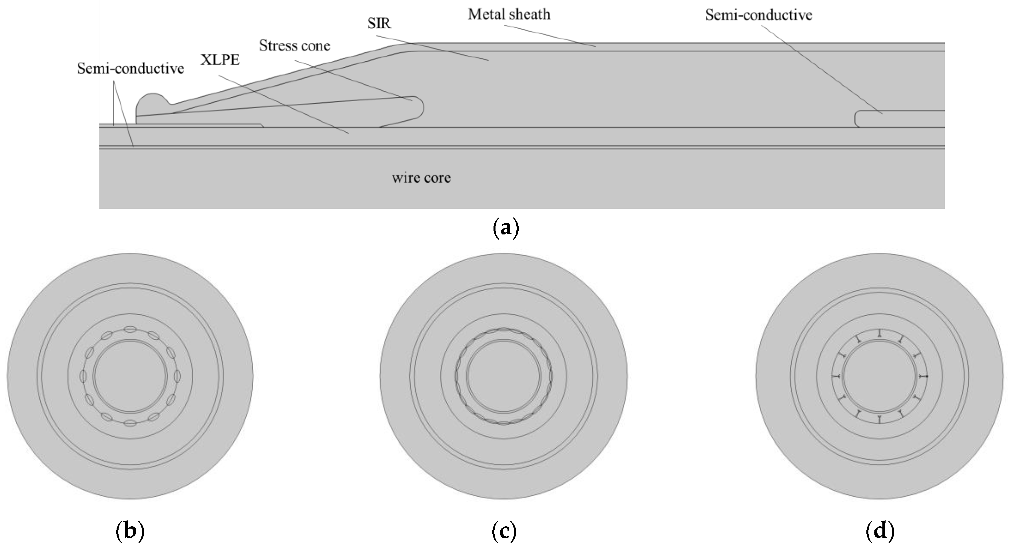
The cable accessory installation process involves stripping the cable metal shield layer and insulation layer, resulting in a more concentrated electric field at the fracture. A stress cone structure can effectively improve the electric field distribution at the fracture. Additionally, in the process of cable joint production and long-term operation, the cable main insulation and stress cone/silicone rubber insulation interface will inevitably develop air gaps, impurities, and other defects. The existence of defects will have an impact on the cable grounding current in the long-term operation of the cable; by the action of the impact voltage, extreme temperature, and other factors, interface defects will aggravate the aging of the cable, and in serious cases will lead to interface discharge, affecting the safe operation of cable accessories.
Due to the complex structure of the cable attachment, a simulation model is selected as the intermediate connector part of a 10 kV distribution cable, and the cross-sectional area of the cable core is 300 mm2. In the simulation, the cable attachment structure of the stress cone three combination point was at the cut surface; this is located at the combination point of the three materials of the stress cone, cable insulation, and reinforced insulation. The structure is complex and defects are very easily produced and developed; therefore, there is the need for a defect simulation study.
The stress cone bonding point is shown in
Figure 1, the position is located at the junction of the stress cone, cable insulation, and reinforced insulation. The structure is complex and defects are very easily generated and developed; thus, defect simulation studies are needed.
We carried out two-dimensional modeling of the cross section of the above cable joint part. Considering that the main problem in the joint is damp in the cable joint, in the distribution network, a parallel trench clamp is used to connect the cable conductor with the overhead conductor. Therefore, when making cable joints, there is no waterproof sealing treatment in the outdoor cable terminal production process. The cable terminal is under sunny and rainy conditions for a long time; imperfect waterproof sealing treatment will cause water to seep into the cable conductor. Since the conventional manufacturing process of the cable intermediate joint can only prevent water from seeping into the main insulation of the cable from the outside, but not from the inside of the cable, water will penetrate the intermediate joint through the surface seam of the bare strand conductor. After a long period of time, the water seepage inside the cable will spread through the whole cable, which will reduce the insulation of the cable. In severe cases, this will cause cable failure and affect the safe operation of the distribution network.
The different types of interface defects of composite insulation structures can be roughly divided into the following categories: (1) Gas impurity defects such as interface bubbles or air gaps caused by improper operation during cable joint fabrication or electrochemical reactions of insulating materials during long-term operation. (2) Liquid impurity defects such as water droplets or water films at the interface caused by moisture in cable joints during long-term operation. (3) Under the condition of long-term coexistence with water, the insulation material forms various dendritic micro channels or air gaps filled with water due to the action of the electric field, that is, the water treeing of the insulation material.
The parameters of each layer of the cable joint are adjusted after wetting; the models of common wetting defects of cable joints are added, such as water droplets, water films, water trees, etc. Due to the influence of wetting, the defects of the cable joint have local wetting and overall wetting development periods. The simulation of different defect periods of the cable joint was carried out to obtain the calculation results of the magnetic flux density of the cable joint and the harmonic analysis results of the grounding current.
In this study, the above three typical defect types are modeled.
Figure 1 is a schematic diagram of the cable accessory interface defect model.
The effects of defect type, size, and location on the interface magnetic field distribution are considered in this study.
Figure 1b is a schematic diagram of water droplet defects; the long half-axis of the ellipse is 1.5 mm and the short half-axis is 0.5 mm.
Figure 1c is a schematic diagram of water film defects; the long half-axis of the ellipse is 1.5 mm, the short half-axis is 0.5 mm, and the water film defects were modelled as a number of connected small water droplets in the actual situation.
Figure 1d is a schematic diagram of water tree defects. In this study, first of all, at the same position of the accessory, the type of defect and the degree of moisture were changed and the influence of different types of defects on the magnetic field and harmonic current under different degrees of moisture was determined. Secondly, the influence of the same defect at different positions on the magnetic field and harmonic current is discussed.
2.2. Calculation Model
In this paper, we will use finite element software to simulate the electromagnetic field of a power cable in different states based on Maxwell’s basic equations of the electromagnetic field. Maxwell’s equations are based on the fundamental law of electromagnetic fields, which has been summarized and improved based on the introduction of the concept of displacement current, and can correctly reflect the relationship between the physical quantities in the electromagnetic field. Maxwell’s equations are the basic equations of electromagnetic fields.
The differential form of Maxwell’s equations is as follows:
where the meaning of ∂ is the partial differentiation of the variables, ∇ is the partial derivative of a vector, which is a vector, H is the magnetic field strength (A/m); J is the current density (A/m
2); D is the potential shift (C/m
2); E is the electric field strength (V/m); B is the magnetic induction strength (T); t is a time variable, and ρ is the charge body density (C/m
3). Both the study of static fields and the study of eddy current fields were derived on the basis of Maxwell’s set of equations.
The cable core is given a certain current-carrying capacity, which will generate an alternating magnetic field, which will in turn generate an induced current. In this model, both a magnetic field and a current are present, and in order to investigate the effect of added defects on the grounding current, the “current” interface is used.
The combined solution of a finite element model and a magnetic field model sometimes requires adjusting the solver settings. A coupled direct solver was used to solve the current problem.
The electromagnetic field satisfies the governing equations:
and has the constitutive equation (math.):
where
is the vacuum permeability and
is the relative permeability, σ is the electrical conductivity,
is the critical current density, E is the electric field strength,
denotes the relative permittivity, and
denotes the vacuum permittivity.
In the 2D finite element electric field model, an AC current of 300 A/50 Hz is added to the wire core and the air boundary is insulated from the magnetic field. Therefore, the magnetic field finite element model corresponds to the edge-value problem of
The above equation can be visualized as follows: On the boundary plane, the magnetic induction line is tangent to the interface. Since the cable structure has an axisymmetric structure, meshing is performed by a physical field control grid, and the grid around the defects is refined. The complete grid contains 173,428 domain cells and 5569 boundary cells.
2.3. Simulation Parameter Acquisition
The dielectric constants of the insulation materials required for the electric field simulations were obtained using broadband dielectric spectroscopy system measurements. The test specimens were sliced from cable accessories with a diameter of 20 mm and thicknesses of 0.15 and 0.3 mm for XLPE and SIR(Silicone Rubber), respectively, and cleaned and dried with anhydrous ethanol before the experiment.
The calculation uses the relative permittivity of XLPE/SIR at the average cable operating temperature of 60 °C, and the relative permittivity of both is 2.15 and 2.81, respectively. A value of 6517 B was used to test the conductivity of the damp cable, and the relative permeability data of each layer of the cable were measured using a relative permeability tester. We conducted the test on non-damp cable joints as well as damp cable joints (after January); the test results are shown in
Table 1 and the parameters after 1 month of accelerated dampening are shown in
Table 2.
3. Effect of Defects on the Magnetic Flux
According to
Section 2.1, a two-dimensional model of the cable was created and the parameters were set to simulate the magnetic field of the cable. There is only one core in the single-core cable, and so mutual influence does not exist; thus, the distribution of the magnetic field in the single-core cable is constant, but the amplitude will change with the externally applied current. The magnetic field at t = 15 ms and the magnetic field distribution in the normal state are shown in the figure for comparison.
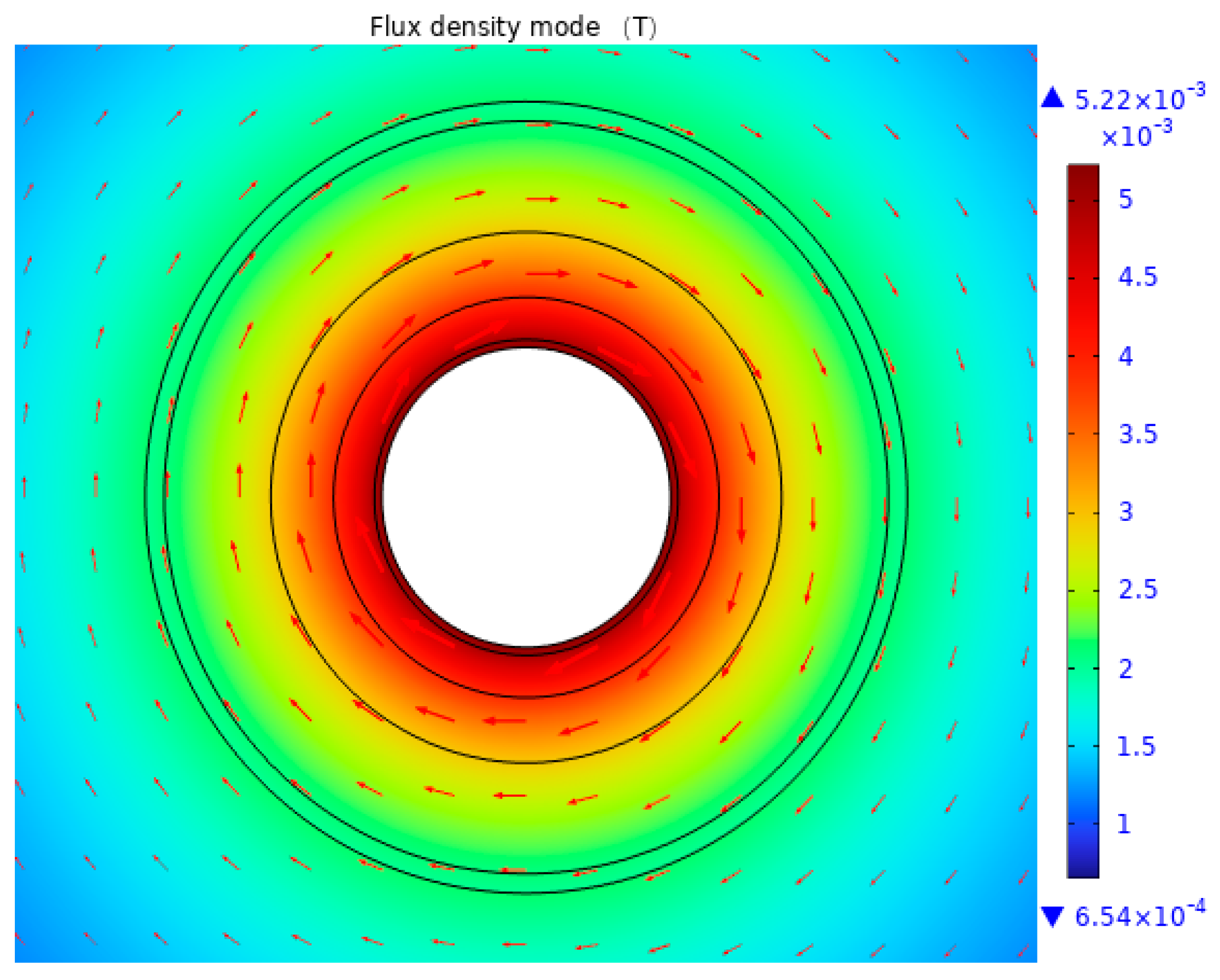
3.1. The Magnetic Field of Cable Accessories in Good Condition
As can be seen from
Figure 2, the maximum flux density occurs near the conductor with a value of 522 mT and gradually decreases from the inside to the outside of the insulation layer.
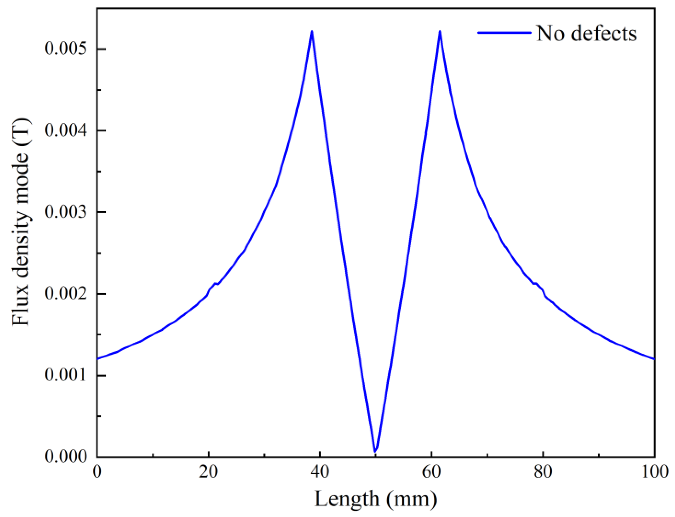
An observation line of the cable diameter length is taken from the center of the cable along the radial direction, and the magnetic flux density at t = 15 ms was calculated. The obtained curve is more illustrative of the distribution of the magnetic induction intensity inside the cable, as shown in
Figure 3. Research on the simulation and analysis of the magnetic field of cables already exists, and simulation result patterns are consistent with this paper, which qualitatively verifies the accuracy of the simulation in this paper [
20,
21,
22].
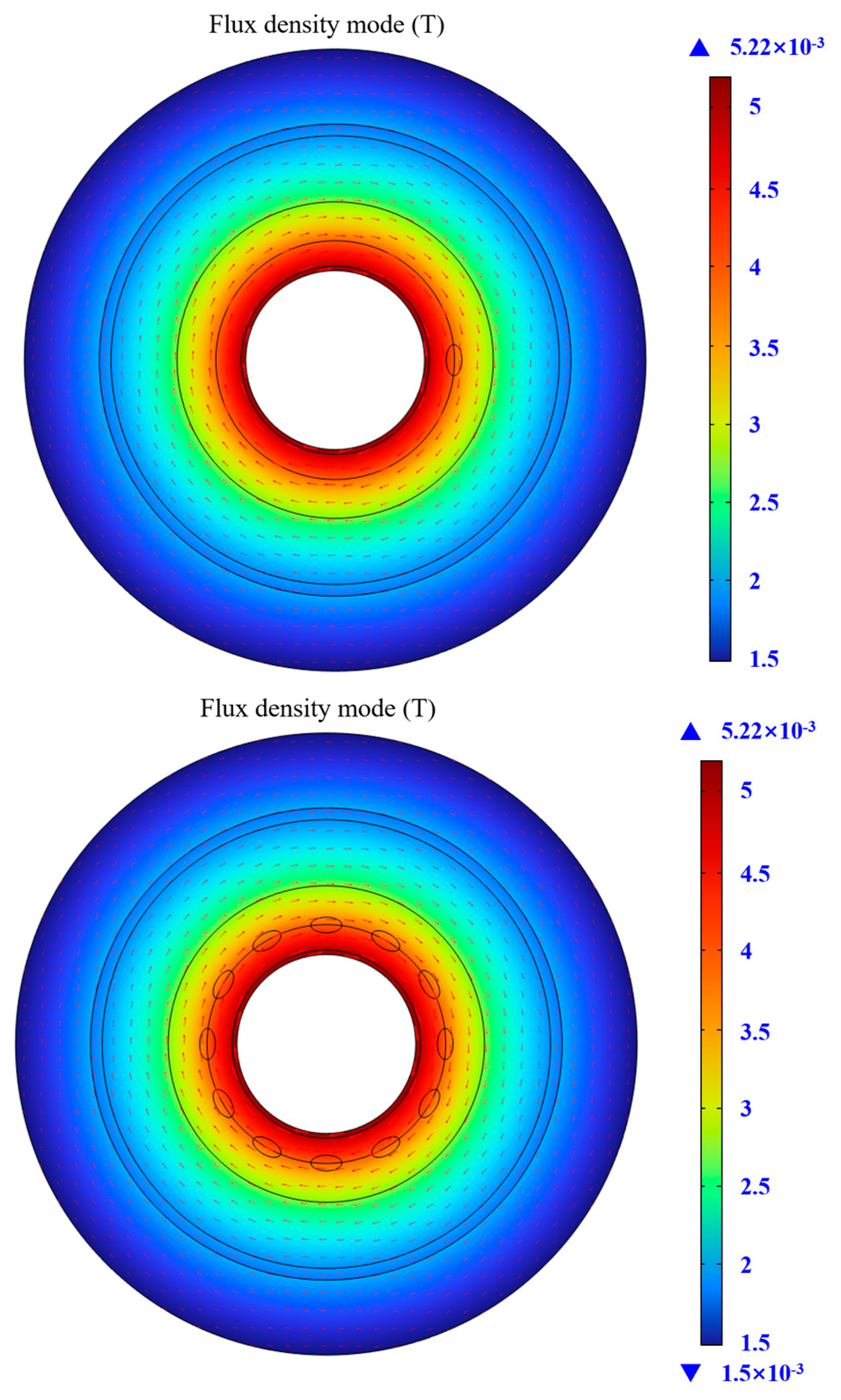
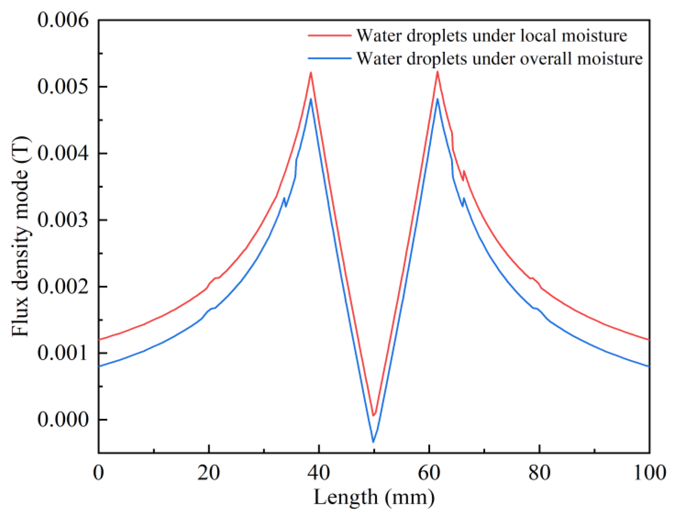
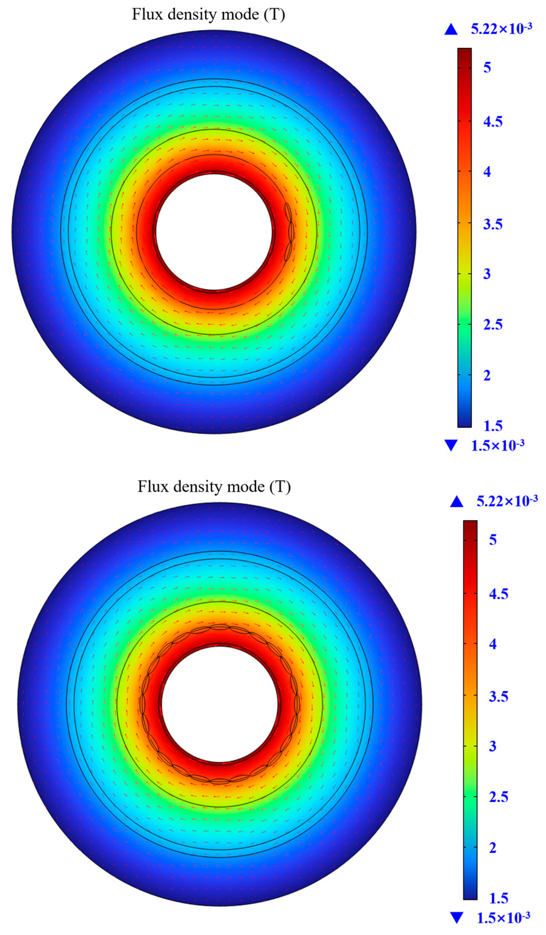
3.2. Effect of Water Droplet Defects on the Magnetic Flux
The simulation of the magnetic field of the cable in the presence of water droplets and the magnetic field distribution at t = 15 ms for different defect degrees are shown in
Figure 4 and
Figure 5.
The magnetic field at the water droplets changed significantly, and the most significant magnetic induction distortion occurred on the side of the water droplets away from the cable core. The magnetic flux density decreased near the outer XLPE layer, the magnetic flux density clearly decreased in the inner SIR distortion, and the maximum magnetic induction intensity value in the whole cable was 551 mT, which is significantly larger than the value in the normal state. The magnetic flux density at the outer sheath of the cable also distorted with the increase in moisture, and the flux change caused a current change and produced a harmonic current. In addition, the magnetic induction intensity in the cable insulation structure changed significantly, except for the magnetic induction intensity near the air gap. The rest of the cable was uniformly distributed from inside to outside in a gradually decreasing manner.
Comparing the effect of water droplet defects on magnetic flux at different levels of moisture, it was found that the flux caused by water droplet defects did not change much for different levels of moisture.
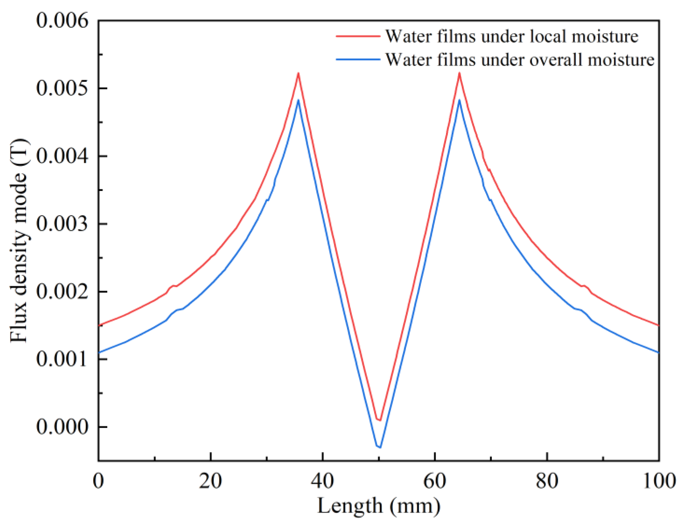
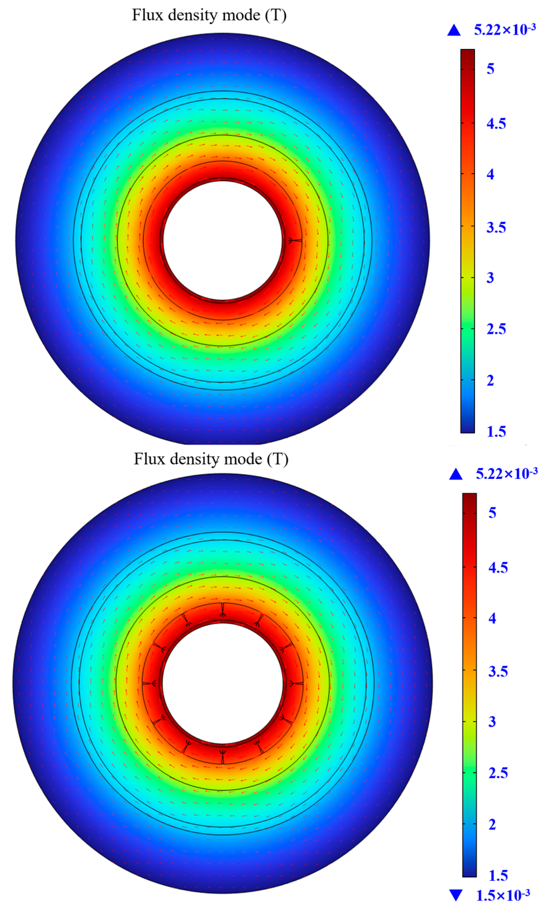
3.3. Effect of the Water Film Defects on the Magnetic Flux
The simulation of the magnetic field of the cable in the presence of a water film and the magnetic field distribution at t = 15 ms for different defect degrees are shown in
Figure 6 and
Figure 7.
The effect of the introduction of local moisture water film defects and water droplet defects on the magnetic flux distortion law is similar. In the water film defect, in close proximity outside of the XLPE layer, the magnetic flux density drops, and inside the SIR, the magnetic flux density drop is obvious. The maximum value of the magnetic flux density increased by 0.157 mT compared to the water droplet defect scenario due to the shape of the water film and the water droplet being different; the magnetic field distortion is caused by this difference. The distortion of the magnetic flux density in the cable sheath is different from that of the water droplet scenario, and it is inferred that harmonic currents will be created with different distortion degrees.
Comparing the effect of water film defects on magnetic flux at different degrees of moisture and different defect locations, it is found that the water film and water droplet change patterns are similar, and the magnetic flux caused by water film defects at different degrees of moisture does not change much.
3.4. Effect of Water Tree Defects on the Magnetic Flux
The simulation of the magnetic field of the cable in the presence of water trees and the magnetic field distribution of different defect degrees at t = 15 ms are shown in
Figure 8 and
Figure 9.
The harmonic distortion caused by local water tree defects is more intense; the flux density at the location of the water tree defects is severely distorted, the flux density oscillates at the location of the water tree, and the flux densities on the outside of the XLPE layer and the inside of the SIR are affected by the defects with different degrees of distortion. Comparing different degrees of damp defects, the flux density at the location of the outer sheath of the cable changes significantly, the flux density change in the cable sheath causes variation in the harmonic current, and the degree of current distortion caused is more serious than the distortion cause by water droplet and water film defects.
Comparing the effect of water droplet defects on the magnetic flux of the sheath at different degrees of moisture and different defect locations, it is found that after adding the same defects at different locations, the water tree defects at the three bonding points cause greater changes in the magnetic flux density of the sheath. At the same cut locations, the flux density of the sheath changes more significantly as the degree of moisture increases. Whether the magnetic flux density increases or decreases, there is a certain degree of change in Φ, which causes a high frequency current, causing current harmonics.
4. Effect of Defects on the Harmonic Ratio of the Grounding Current
4.1. Comparison of Cable Accessory Ground Current Waveforms under Different Defects
The waveform of different defective ground currents under different degrees of moisture is shown in
Figure 10.
By observing and comparing the ground currents of cable joints with different types of defects with different degrees of dampness, it can clearly be seen that the harmonic distortion caused by the overall damp defect is more serious. The waveform distortion of the ground current is also different with different types of defects, and the harmonics caused by different types of defects are different, which proves that different types and degrees of defects will cause different harmonics. By analyzing the grounding current waveform distortion rate in a preliminary analysis of different defects with different degrees of moisture distortion and degrees of current, the grounding current distortion rate was determined and is shown in
Figure 11.
In the case of local moisture defects caused by cable joint current distortion, different types of defects caused different current harmonic distortion rates, and the difference between the current distortion rates of the droplet and water film defects is not large, at about 1.5%. The magnetic flux changes caused by the water tree defects fluctuate more, leading to the cable joint harmonic distortion rate being significantly higher than with the other two defects.
In the case of overall moisture, a large number of water tree defects caused by the cable joint current from the waveform show more obvious distortion. Water film and water droplet defects also caused different degrees of current distortion. The effects of different types of defects on the current harmonic distortion rate are different; water droplet and water film current distortion rates were 1.78% and 2.04%, respectively, while moisture caused by water tree defects led to a current distortion rate of 3.05%. The defect structure of the water tree and the fluctuation of the flux variation caused by the water tree led to a significantly higher harmonic distortion rate of the cable joints than the other two defects.
4.2. The Percentage of Cable Ground Current Harmonics Caused by Different Defects
A Fourier analysis was performed on the current waveform in
Figure 10, and the results of harmonic analyses are shown in
Figure 12 and
Figure 13.
In contrast, in the local dampness case, the third and fifth harmonics of water droplet defects accounted for a higher percentage, close to 2%, and the seventh harmonic accounted for the lowest percentage, at less than 1%. The highest percentage of moisture film defects was from the seventh harmonic; the third, fifth, and ninth harmonics are similar and slightly lower than the seventh harmonic percentage; and the third and seventh harmonics account for the highest proportion, about 4%, followed by the fifth and ninth harmonics, at about 2%.
Comparing the overall moisture situation, water droplet defects’ fifth harmonic accounted for a relatively high amount, the third harmonic accounted for the second highest amount, and the seventh and ninth harmonic accounted for a similar proportion, less than 2%. The highest percentage belonged to the seventh and ninth harmonics for moisture film defects, and the third and fifth harmonics accounted for a similar percentage. The third and seventh harmonics of water tree defects accounted for the highest percentage, about 6.5%; the fifth harmonic accounted for the second highest percentage, about 5%; and the ninth harmonic accounted for the lowest percentage.
Currently, the defect testing of composite insulation interfaces of cable accessories is still going. A harmonic test platform for defects at the composite interface of cable accessories has been constructed, and in the experiment, different types of defects, such as air bubbles and impurities, were modelled and the harmonic currents caused by the defects were measured and analyzed.


