
A Study on Using Magnetic Abrasive Finishing with a 6-Axis Robot to Polish the Internal Surface Finishing of Curved Tubes

Abstract
:1. Introduction
2. Machining Principle and Experimental Procedure
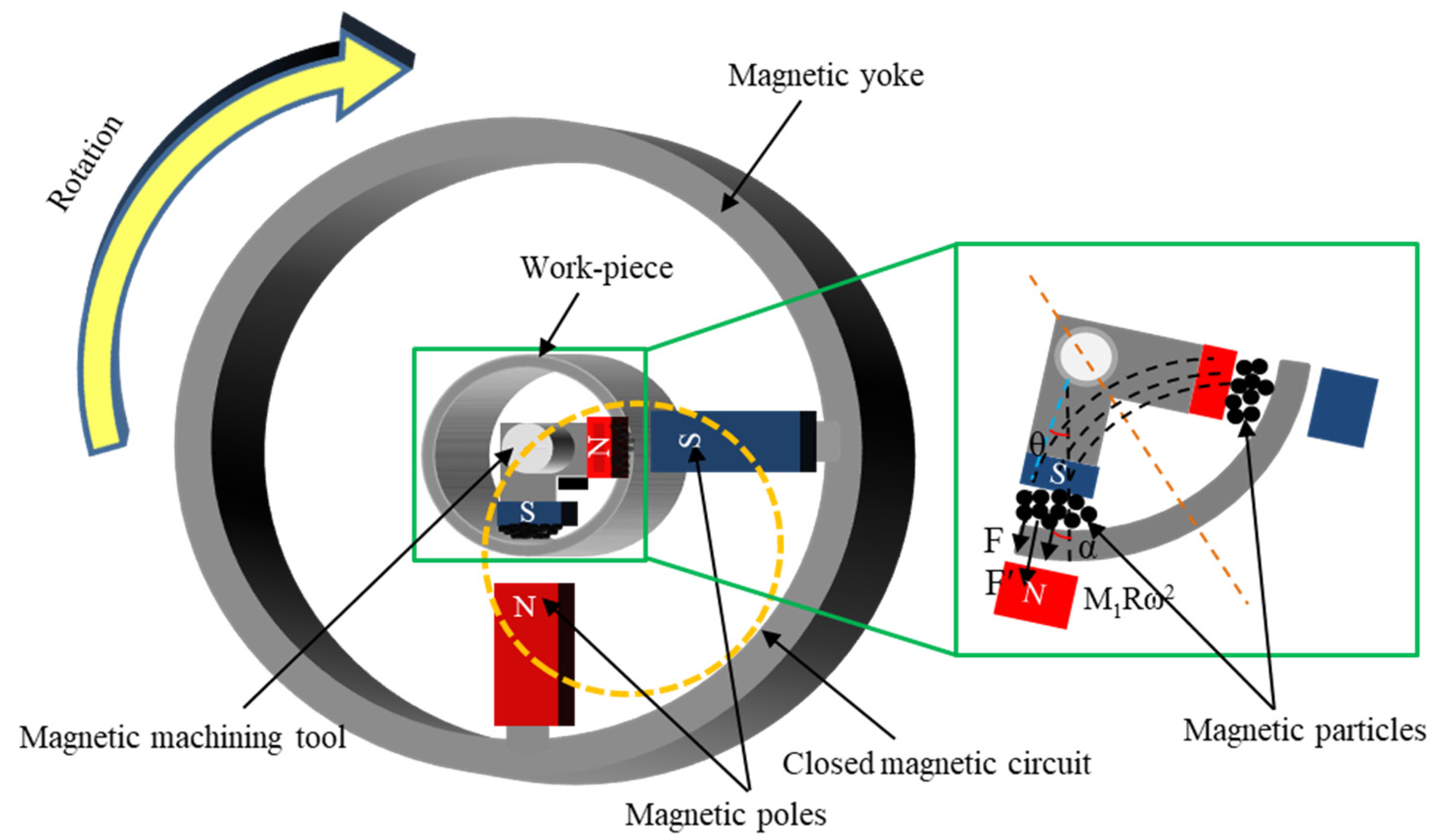
2.1. Machining Principle
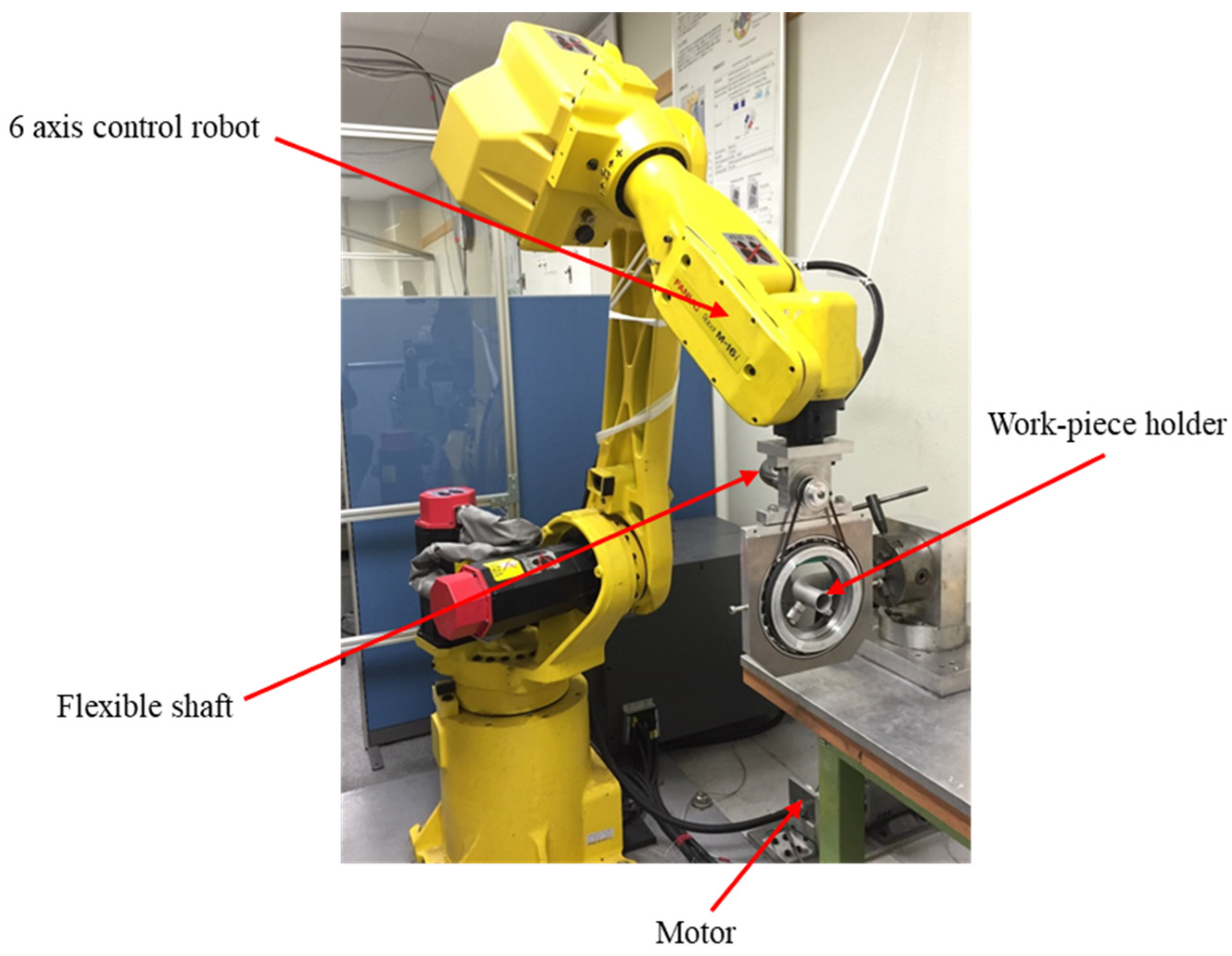
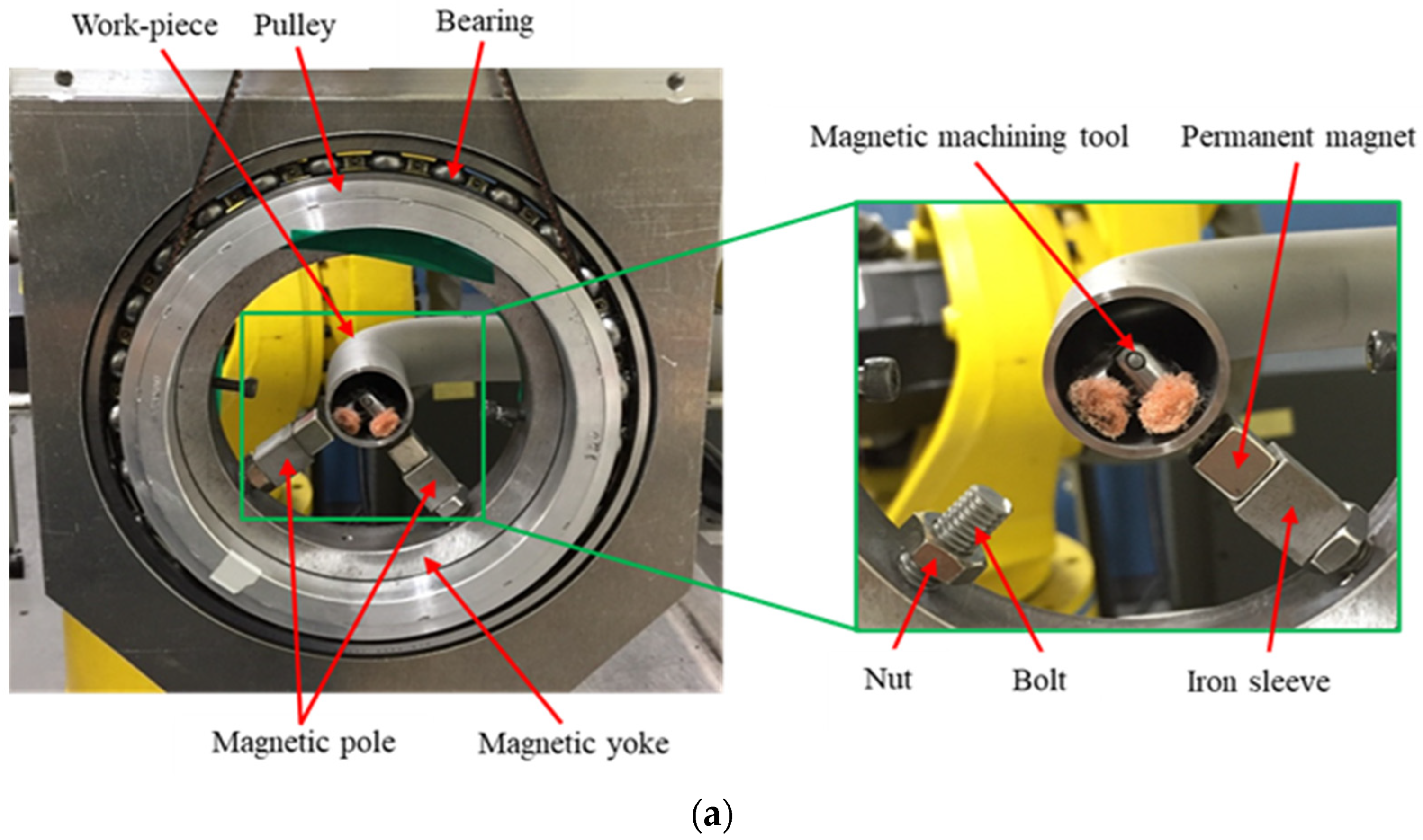
2.2. Experimental Setup and Experimental Procedure
3. Experimental Results
3.1. Initial Machining Stage
3.1.1. Experimental Conditions
- ♦
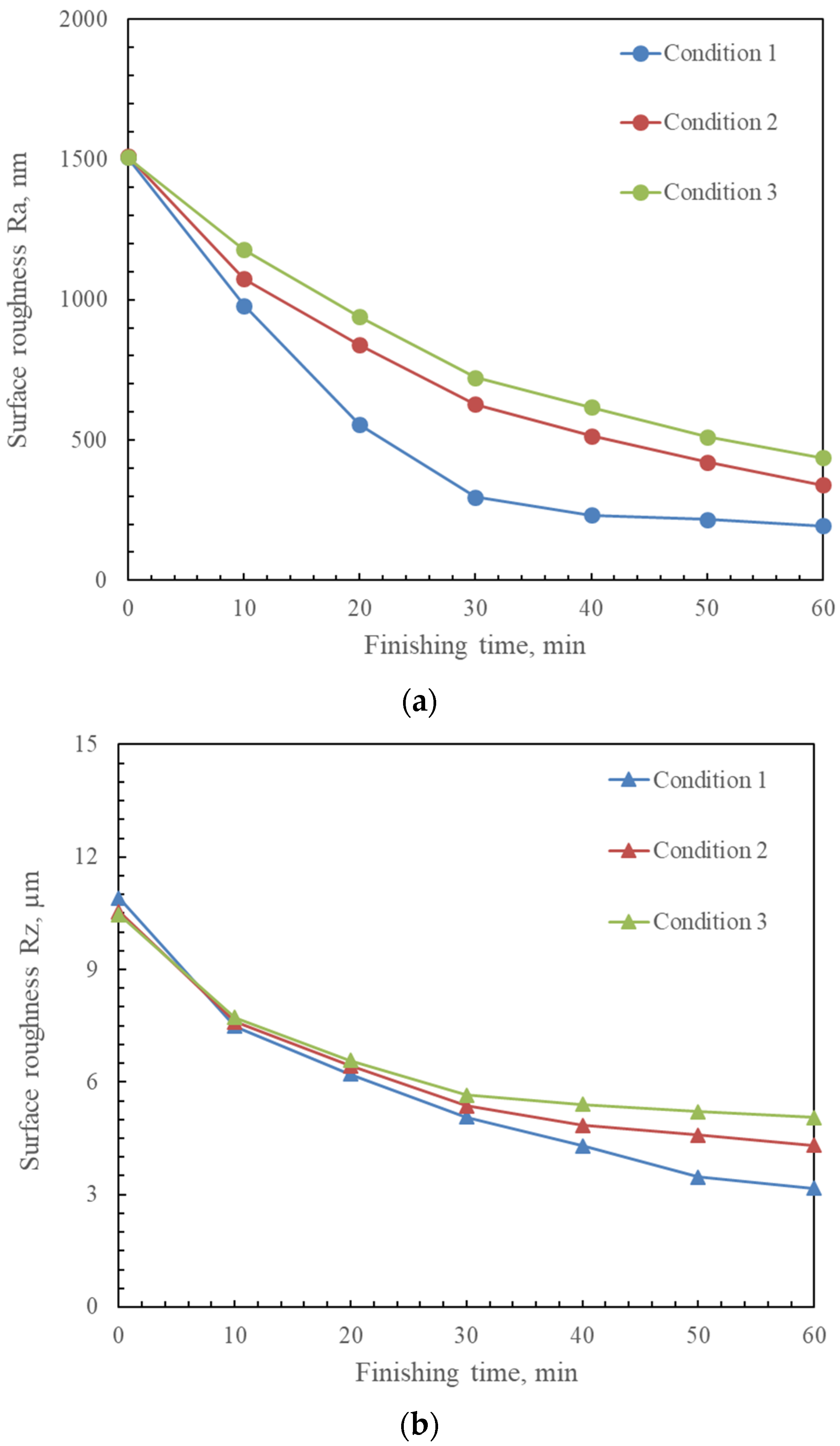
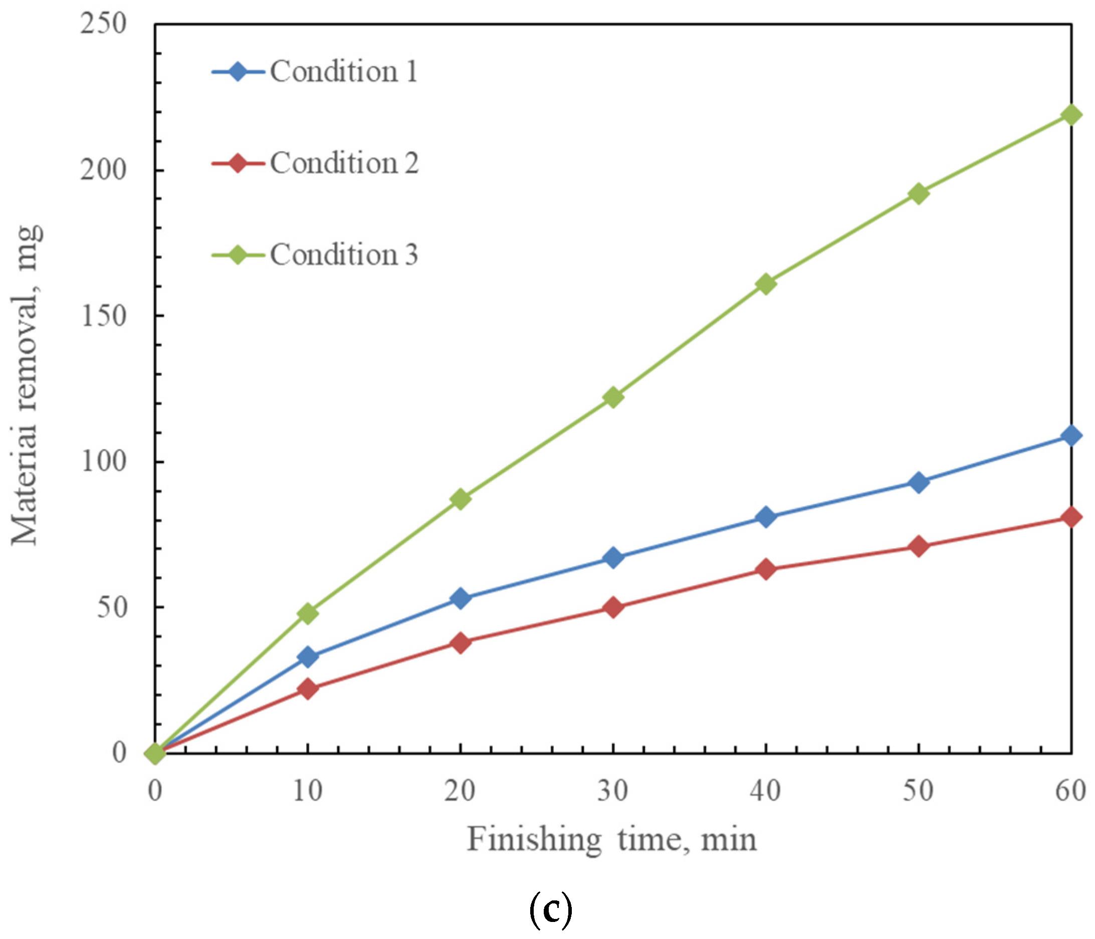
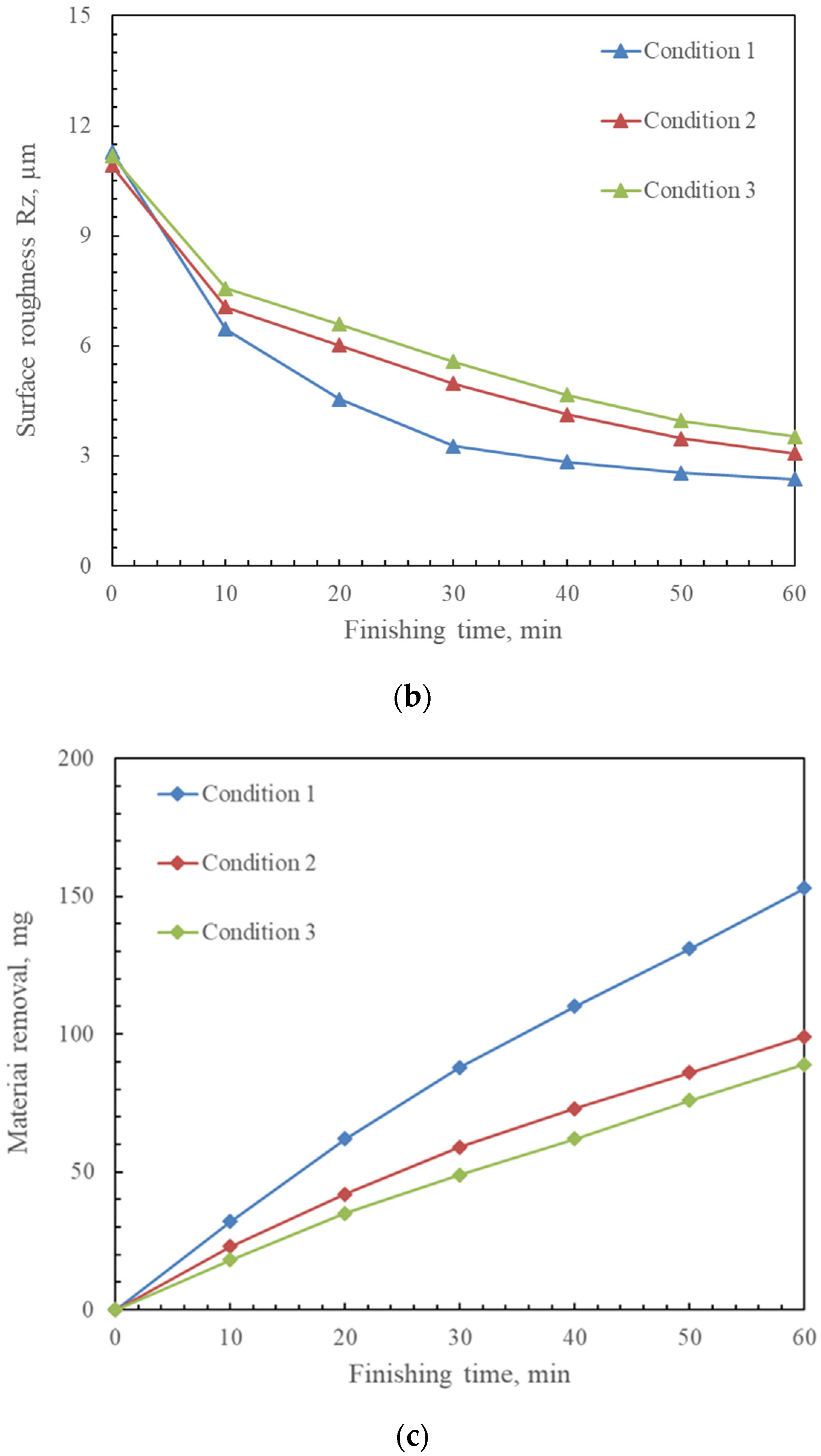
- The experimental conditions of experiment 1 are shown in Table 2. The working gap between the internal and external magnets is 4 mm, and the rotational speed is 360 rpm. To investigate the effect of the total usage of the mixed magnetic abrasive on the finishing characteristics, the total usage of the mixed magnetic abrasive as a variable parameter is 0.6 g (Cond. 1), 0.36 g (Cond. 2), and 0.84 g (Cond. 3), respectively, and the ratio of electrolytic iron particles to the KMX magnetic abrasive is 2:1.
- ♦
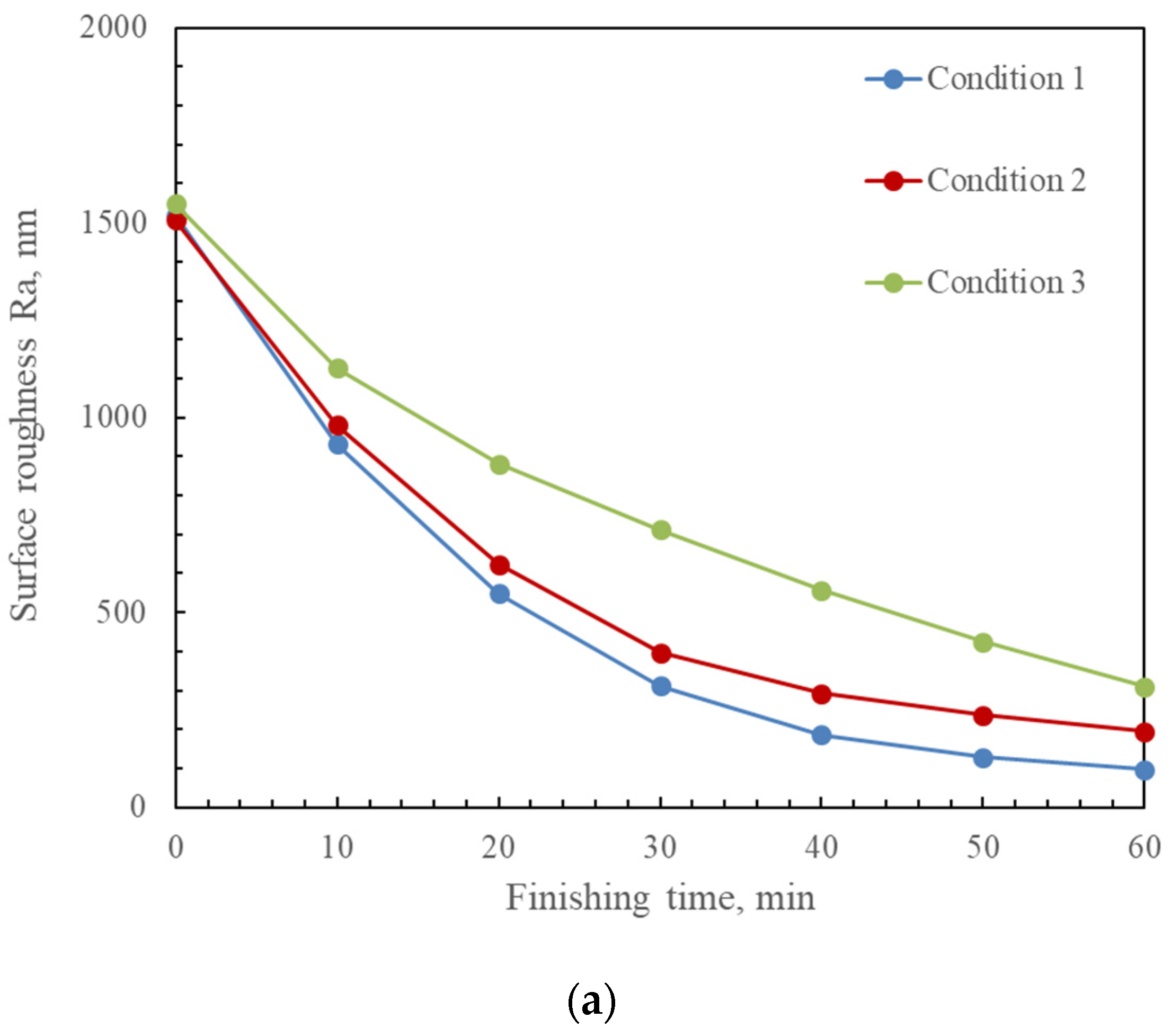
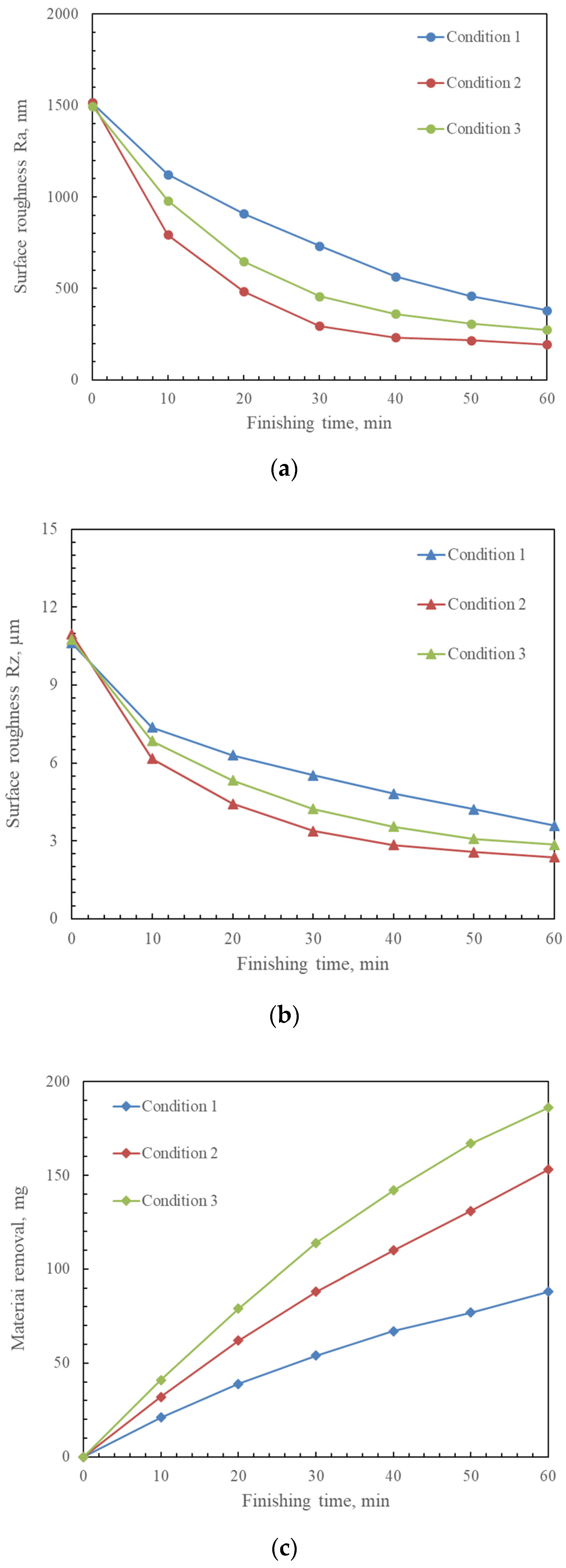
- The experimental conditions of experiment 2 are shown in Table 3. The total usage of the mixed magnetic abrasive is 0.6 g, and the rotational speed is 360 rpm. To investigate the effect of the working gap on the finishing characteristics, the working gap as a variable parameter is 3 mm (Cond. 1), 4 mm (Cond. 2), and 5 mm (Cond. 3), respectively.
- ♦
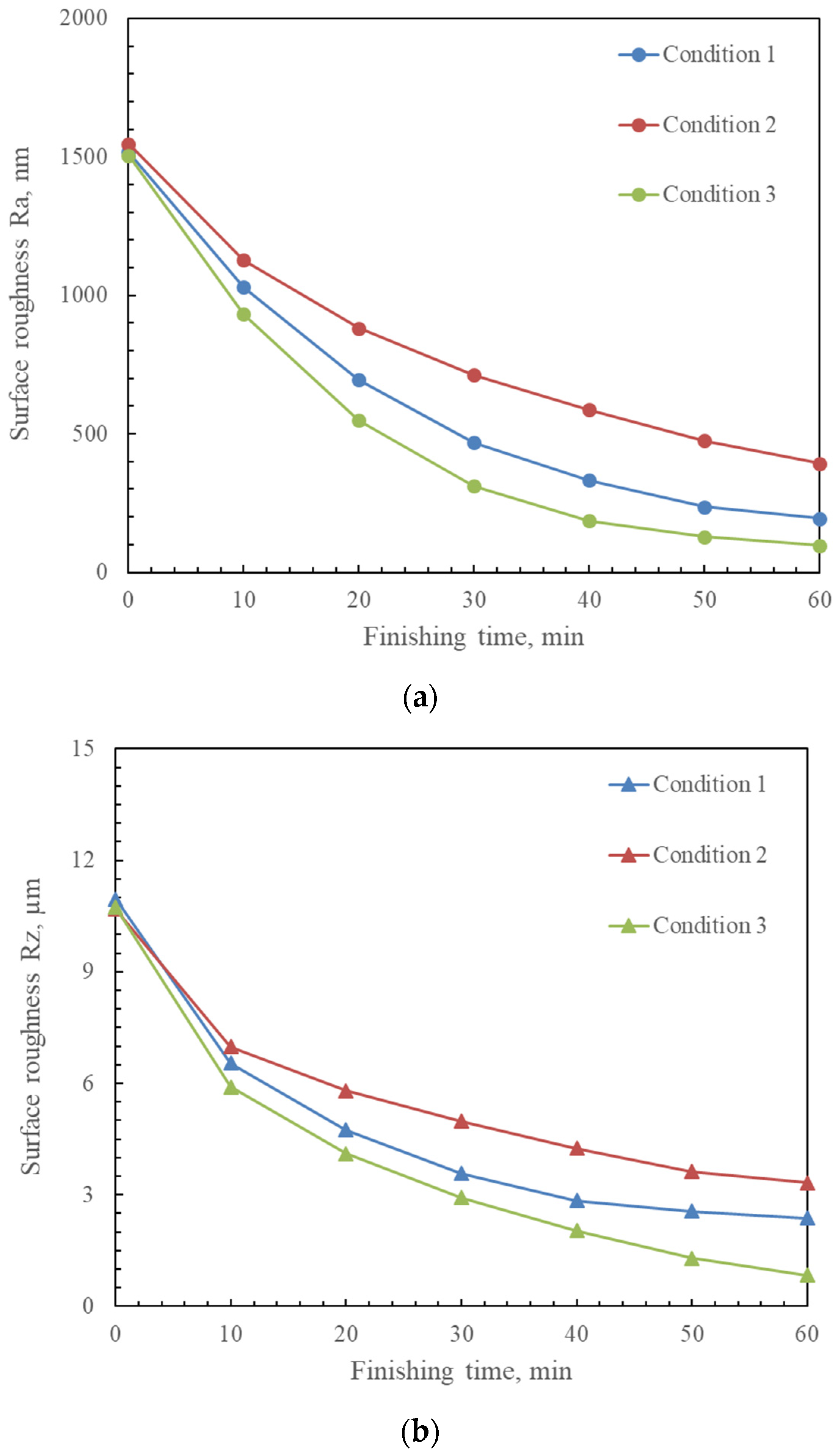
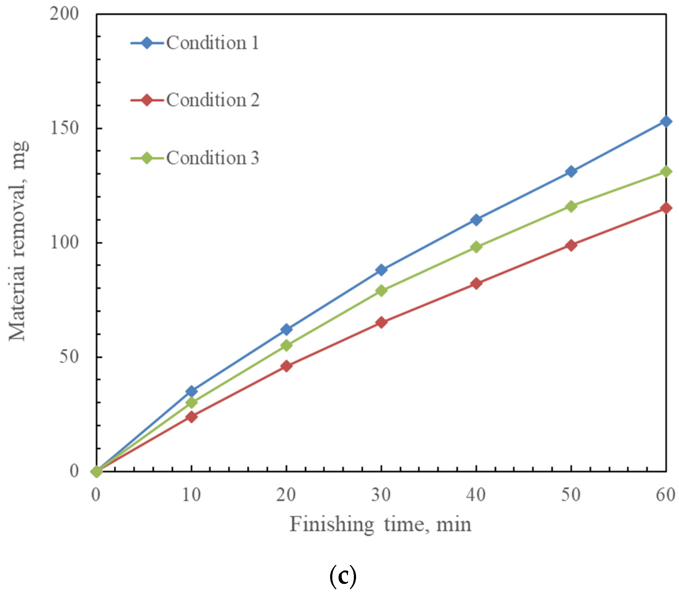
- The experimental conditions of experiment 3 are shown in Table 4. The working gap between the internal and external magnets is 4 mm, and the total usage of the mixed magnetic abrasive is 0.6 g. To investigate the effect of the rotational speed on the finishing characteristics, the rotational speed as a variable parameter is 240 (Cond. 1), 360 (Cond. 2), and 480 rpm (Cond. 3), respectively.
- ♦
- The experimental conditions of experiment 4 are shown in Table 5. The working gap between the internal and external magnets is 4 mm, and the rotational speed is 360 rpm. To investigate the effect of the abrasive combinations with different particle sizes on the finishing characteristics, the detailed abrasives combinations are, respectively, described in Cond. 1, Cond. 2, Cond. 3.
3.1.2. Experimental Results
3.2. Precision Finishing Stage
3.2.1. Experimental Conditions
- ♦
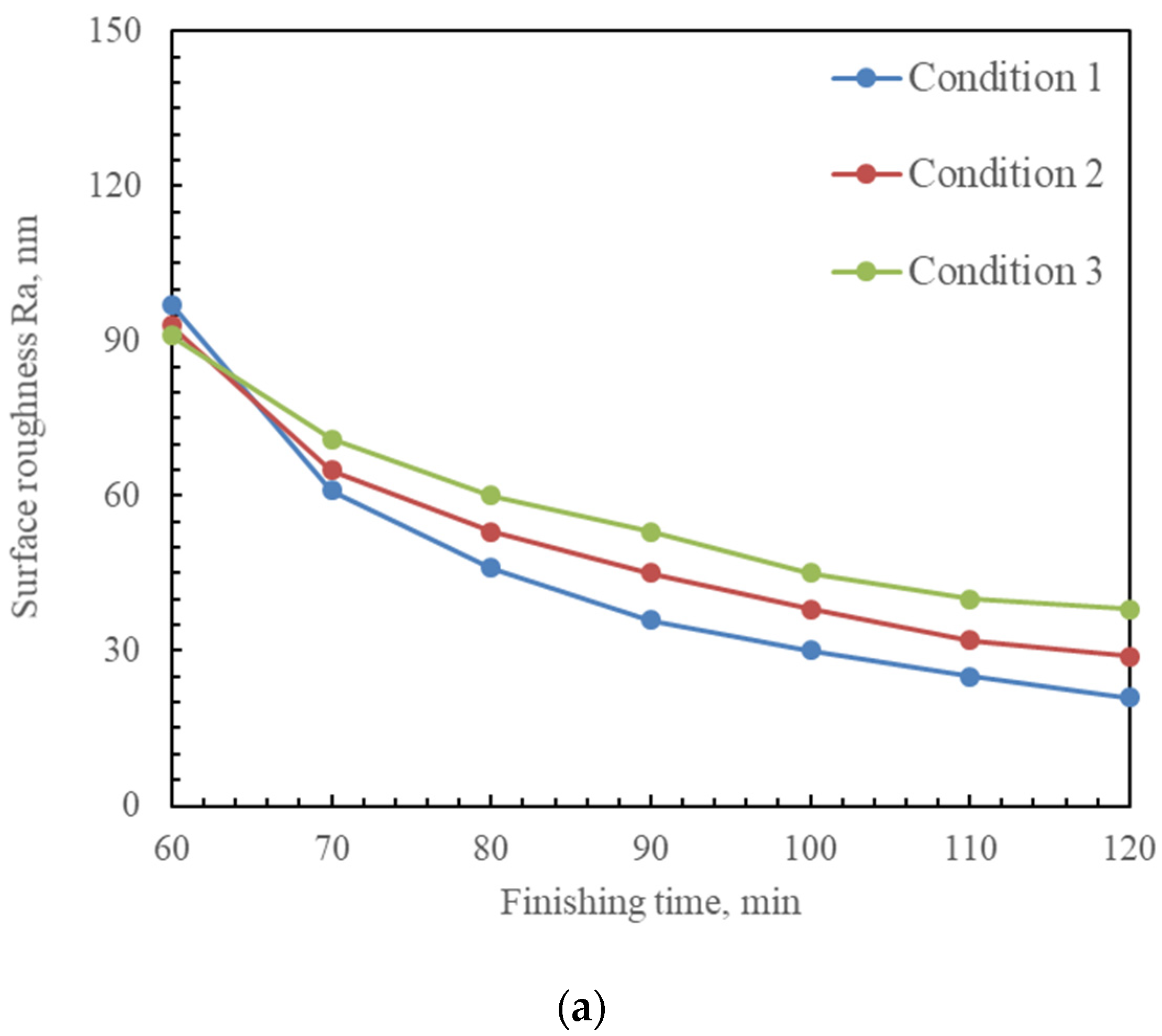
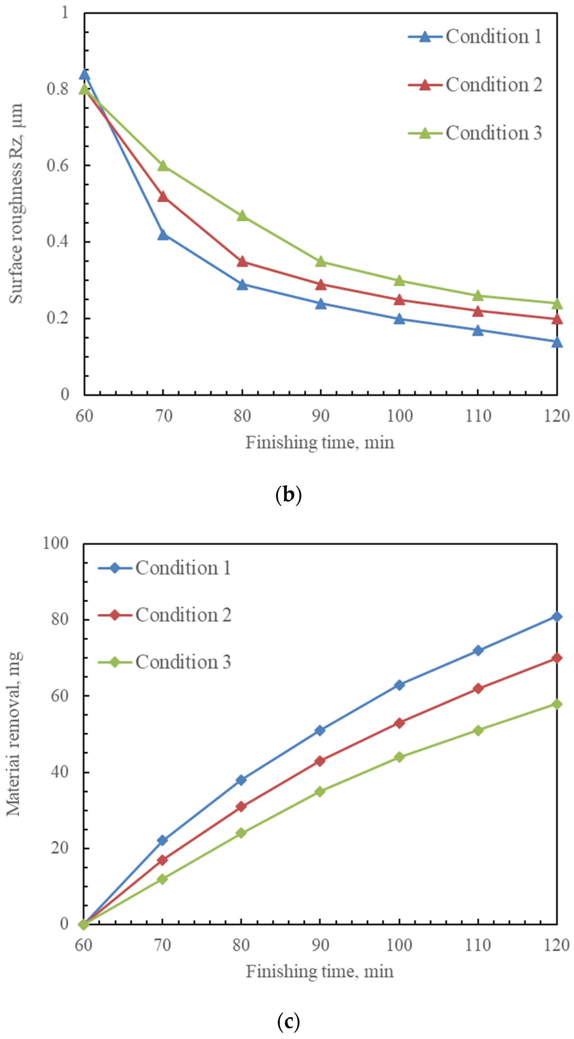
- Table 7 shows the experimental conditions of experiment 5. The feeding speed is 40 mm/min. To investigate the effect of the working gap on the finishing characteristics in the precision finishing stage, the working gap as a variable parameter is 3, 4, and 5 mm, respectively.
- ♦
- Table 8 shows the experimental conditions of experiment 6. The working gap is 4 mm. To investigate the effect of the feeding speed on the finishing characteristics in the precision finishing stage, the feeding speed as a variable parameter is 20, 40, and 80 mm/min, respectively.
3.2.2. Experimental Results
3.3. Multi-Stage MAF Process
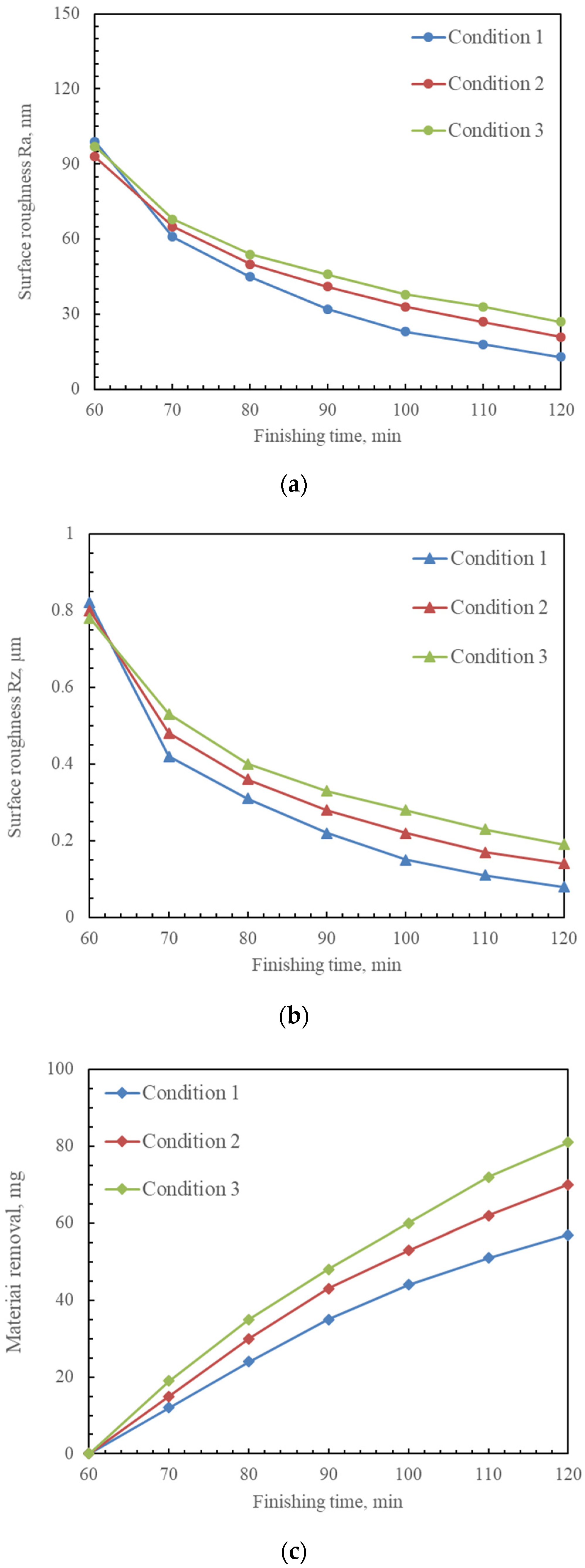
3.3.1. Experimental Conditions
3.3.2. Experimental Results
4. Discussion
5. Conclusions
- A new magnetic abrasive finishing (MAF) method, which used a 6-axis robot with a magnetic machining tool, was proposed to polish the inner surface of the curved tube;
- Firstly, the total supply quantity of mixed magnetic abrasive, working gap, rotational speed, and combinations of abrasives with different particle sizes in the initial machining stage’s parameters were investigated by performing a series of comparative experiments in the initial machining stage;
- Then, the working gap and feeding speed were also investigated by performing a series of comparative experiments in the precision finishing stage;
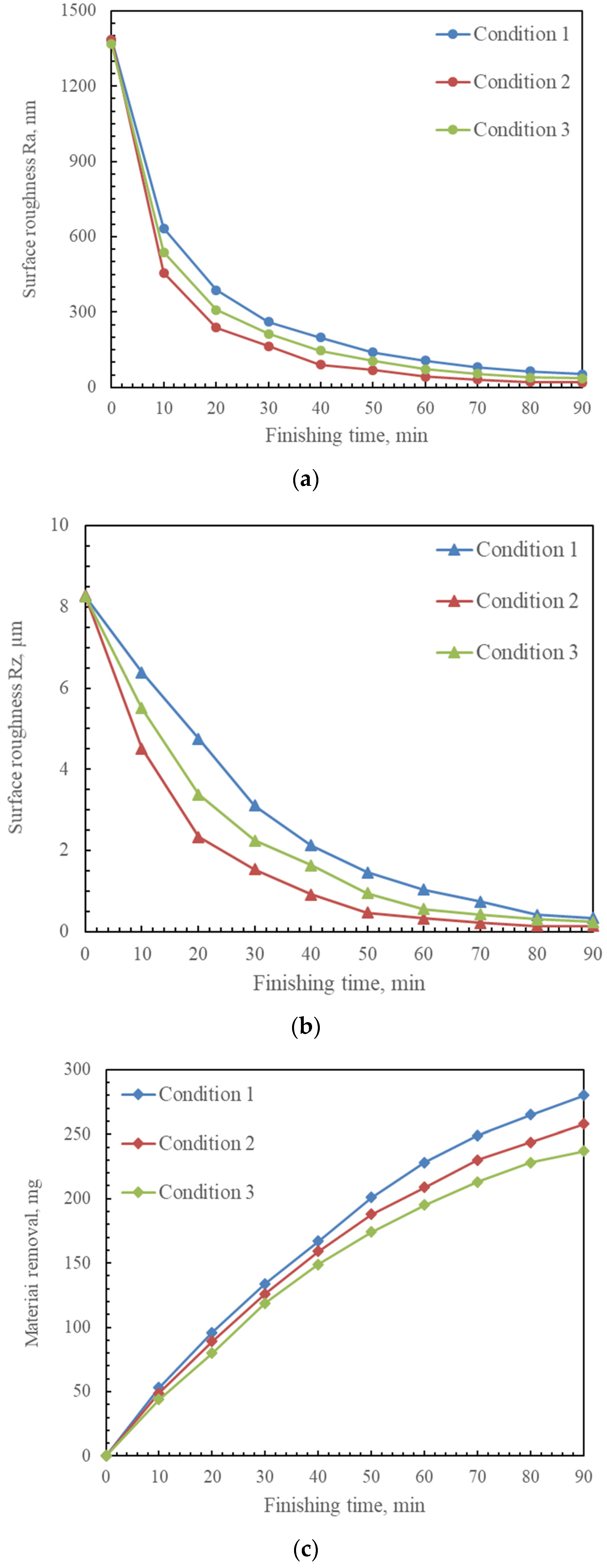
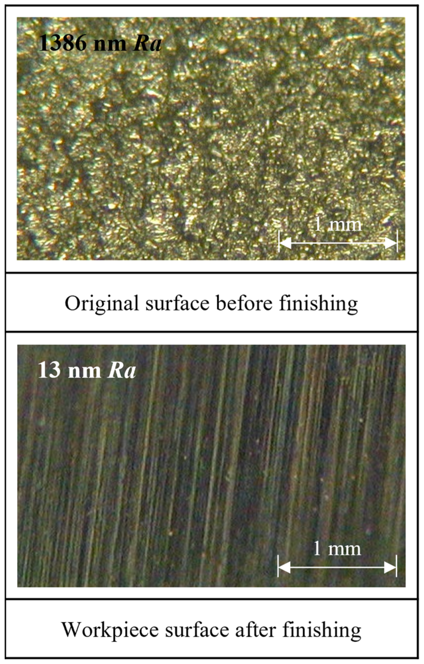
- Based on the experimental investigations into two different machining stages, the experiments of the MAF process were performed in multiple stages. The optimal experimental results showed that the roughness Ra of inner surface reached 13 nm, from an original roughness value of 1630 nm in multiple stages of 105 min MAF process;
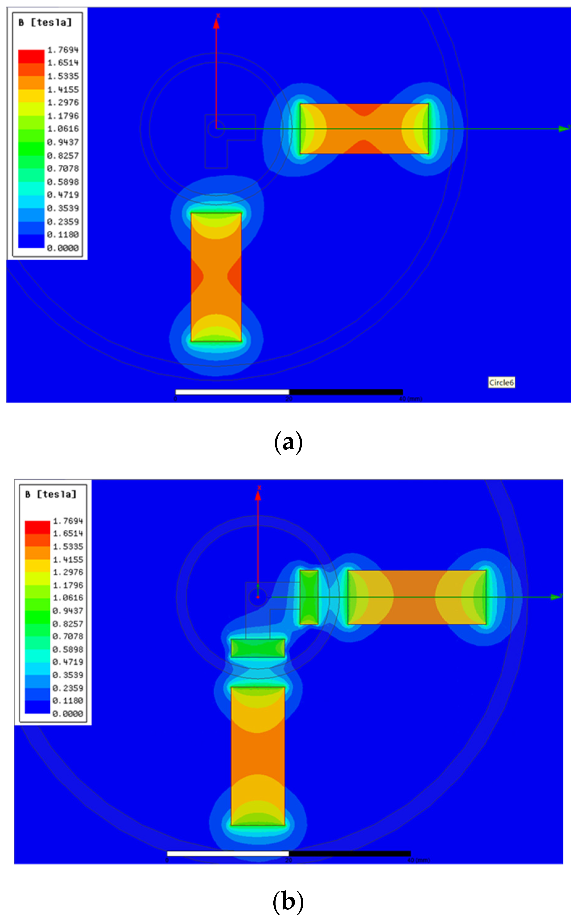
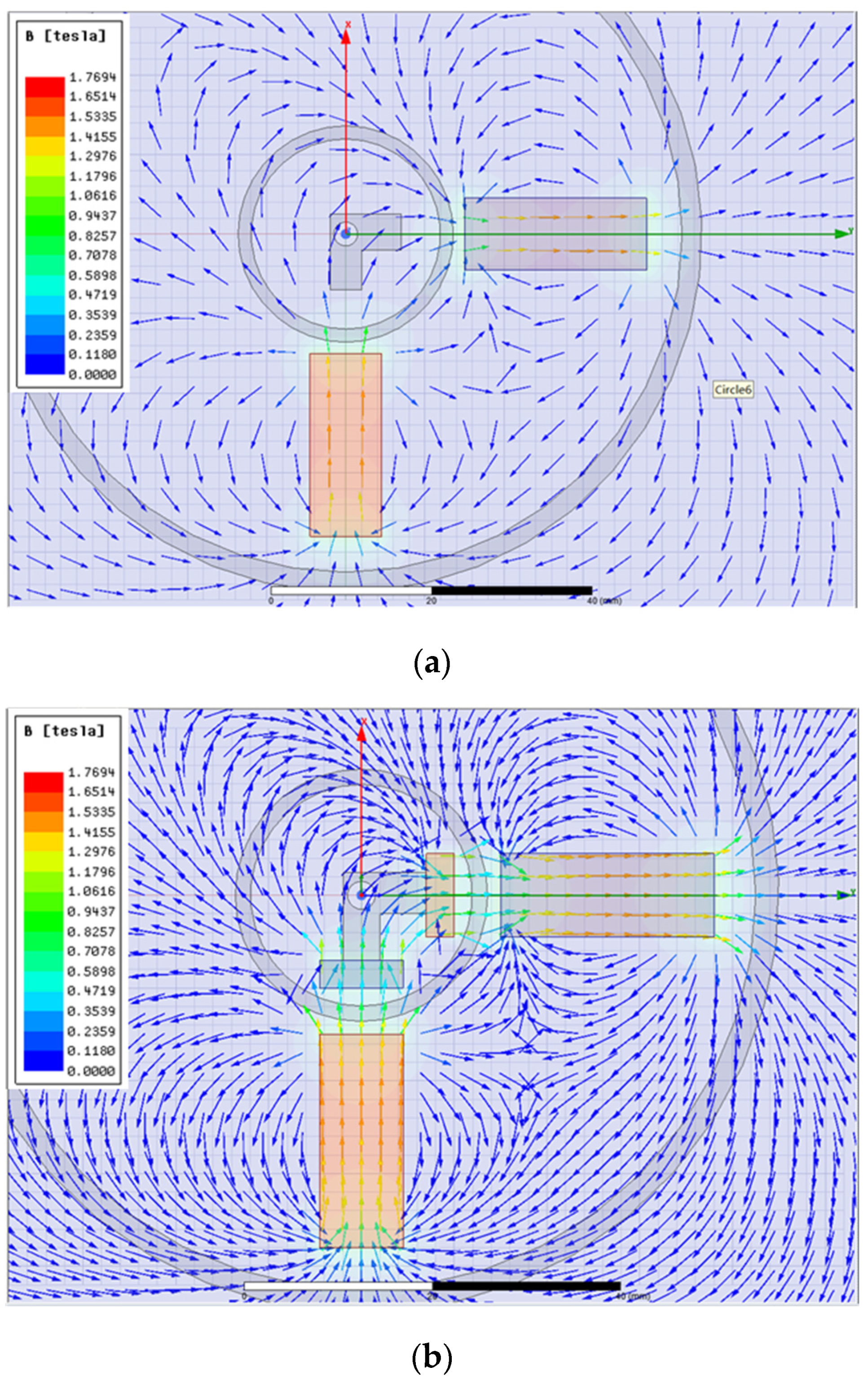
- The magnetic flux density cloud map and the magnetic field line distribution map in the MAF process without and with internal magnetic tool were analyzed in Ansys Maxwell software. By comparing the simulation results, it was revealed that a greater magnetic flux density and a better aggregation effect of the magnetic force lines were generated by inserting internal machining tools into the curved tube in the MAF process.
6. Patents
Author Contributions
Funding
Institutional Review Board Statement
Informed Consent Statement
Data Availability Statement
Acknowledgments
Conflicts of Interest
References
- Kumar, C.G.; Anand, S.K. Significance of microbial biofilms in food industry: A review. Int. J. Food Microbiol. 1998, 42, 9–27. [Google Scholar] [CrossRef]
- Fisher, J.; Kaufmann, E.; Pense, A. Effect of Corrosion on Crack Development and Fatigue Life. Transp. Res. Rec. 1998, 1624, 110–117. [Google Scholar] [CrossRef]
- Hang, W.; Wei, L.Q.; Debela, T.T.; Chen, H.Y.; Zhou, L.B.; Yuan, J.L.; Ma, Y. Crystallographic orientation effect on the polishing behavior of LiTaO3 single crystal and its correlation with strain rate sensitivity. Ceram. Int. 2022, 48, 7766–7777. [Google Scholar] [CrossRef]
- Sun, X.; Zou, Y.H. Development of magnetic abrasive finishing combined with electrolytic process for finishing SUS304 stainless steel plane. Int. J. Adv. Manuf. Technol. 2017, 92, 3373–3384. [Google Scholar] [CrossRef]
- Yamaguchi, H.; Shinmura, T.; Sekine, M. Uniform Internal Finishing of SUS304 Stainless Steel Bent Tube Using a Magnetic Abrasive Finishing Process. J. Manuf. Sci. Eng. 2005, 127, 605–611. [Google Scholar] [CrossRef]
- Deng, Y.M.; Zhao, Y.G.; Zhao, G.Y.; Gao, Y.W.; Liu, G.X.; Wang, K. Study on magnetic abrasive finishing of the inner surface of Ni–Ti alloy cardiovascular stents tube. Int. J. Adv. Manuf. Technol. 2021, 118, 2299–2309. [Google Scholar] [CrossRef]
- Kang, J.; George, A.; Yamaguchi, H. High-speed internal finishing of capillary tubes by magnetic abrasive finishing. Procedia CIRP 2012, 1, 414–418. [Google Scholar] [CrossRef] [Green Version]
- Liu, J.N.; Zou, Y.H. Study on Mechanism of Roundness Improvement by the Internal Magnetic Abrasive Finishing Process Using Magnetic Machining Tool. Machines 2022, 9, 112. [Google Scholar] [CrossRef]
- Shinmura, T.; Takazawa, K.; Hatano, E. Study on magnetic abrasive finishing: Rounding condition and its confirmation by experiment. Bull. Jpn. Soc. Precis. Eng. 1986, 52, 1598–1603. (In Japanese) [Google Scholar] [CrossRef]
- Wang, Y.; Hu, D. Study on the inner surface finishing of tubing by magnetic abrasive finishing. Int. J. Mach. Tools Manuf. 2005, 45, 43–49. [Google Scholar] [CrossRef]
- Yan, B.H.; Chang, G.W.; Cheng, T.J.; Hsu, R.T. Electrolytic magnetic abrasive finishing. Int. J. Mach. Tools Manuf. 2003, 43, 1355–1366. [Google Scholar] [CrossRef]
- Zhang, S.R.; Yang, L.F.; Wu, G.X. Experimental Study on Increasing Magnetic Abrasive Finishing Efficiency of Finishing Nonferromagnetic Materials. Key Eng. Mater. 2007, 359, 300–304. [Google Scholar] [CrossRef]
- Yamaguchi, H.; Shinmura, T.; Ikeda, R. Study of Internal Finishing of Austenitic Stainless Steel Capillary Tubes by Magnetic Abrasive Finishing. J. Manuf. Sci. Eng. 2007, 129, 885–892. [Google Scholar] [CrossRef]
- Hitomi, Y.; Anil, K.S.; Michael, T.; Fukuo, H. Magnetic Abrasive Finishing of cutting tools for high-speed machining of titanium alloys. CIRP J. Manuf. Sci. Technol. 2014, 7, 299–304. [Google Scholar]
- Zou, Y.H.; Liu, J.N.; Shinmura, T. Study on Internal Magnetic Field Assisted Finishing Process Using a Magnetic Machining Jig for Thick Non-Ferromagnetic Tube. Adv. Mater. Res. 2011, 325, 530–535. [Google Scholar] [CrossRef]
- Yang, Y.Z.; Xue, Y.; Li, B.X.; Fu, Y.J.; Jiang, Y.H.; Chen, R.X.; Hang, W.; Sun, X. A Magnetic Abrasive Finishing Process with an Auxiliary Magnetic Machining Tool for the Internal Surface Finishing of a Thick-Walled Tube. Machines 2022, 10, 529. [Google Scholar] [CrossRef]
- Muhamad, M.R.; Zou, Y.H.; Sugiyama, H.S. Investigation of the finishing characteristics in an internal tube finishing process by magnetic abrasive finishing combined with electrolysis. Trans. IMF 2016, 94, 159–165. [Google Scholar] [CrossRef]
- Muhamad, M.R.; Jamaludin, M.F.; Ab Karim, M.S.; Yusof, F.; Zou, Y.H. Effects of electrolysis on magnetic abrasive finishing of AA6063-T1 tube internal surface using combination machining tool. Materialwiss. Werkst. 2018, 49, 442–452. [Google Scholar] [CrossRef]
- Ridha, M.M.; Zou, Y.H. Magnetic Abrasive Finishing of Internal Surface of Aluminum Pipe Using Magnetic Machining Jig. Adv. Mater. Res. 2014, 894, 222–226. [Google Scholar] [CrossRef]
- Wang, C.J.; Cheung, C.F.; Ho, L.T.; Yung, K.L.; Kong, L.B. A novel magnetic field-assisted mass polishing of freeform surfaces. J. Mater. Process. Technol. 2020, 279, 116552. [Google Scholar] [CrossRef]
- Wang, C.J.; Loh, Y.M.; Cheung, C.F.; Wang, S.X.; Ho, L.T.; Li, Z. Shape-adaptive magnetic field-assisted batch polishing of three-dimensional surfaces. Precis. Eng. 2022, 76, 261–283. [Google Scholar] [CrossRef]
- Singh, N.; Kumar, H.; Gill, J.S. Internal Finishing of Aluminium Tube with Sintered Magnetic Abrasive. Int. J. Eng. Appl. Sci. 2016, 3, 76–79. [Google Scholar]
- Han, B.; Liu, L.X.; Chen, Y. Optimization of Process Parameters for Magnetic Grinding Method to Process the Inner Surface of Pipe Bends. Chin. J. Mech. Eng. 2015, 26, 814–817. (In Chinese) [Google Scholar]


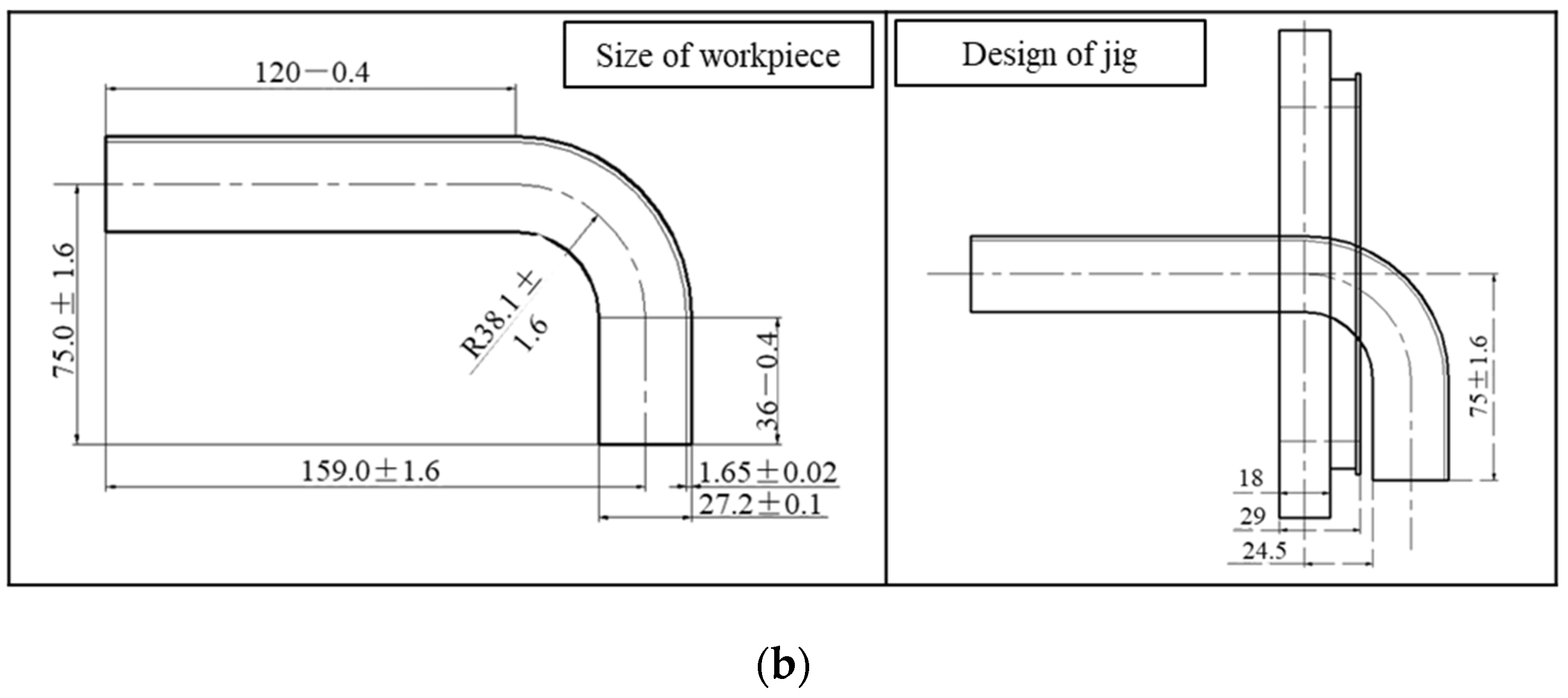
| Workpiece | SUS304 stainless steel 90° bent tube (Ø27.2 × Ø23.9 mm, L1 120 mm, L2 36 mm, R 38.1 mm) |
| Finishing length | 70 mm |
| Feeding speed | 40 mm/min |
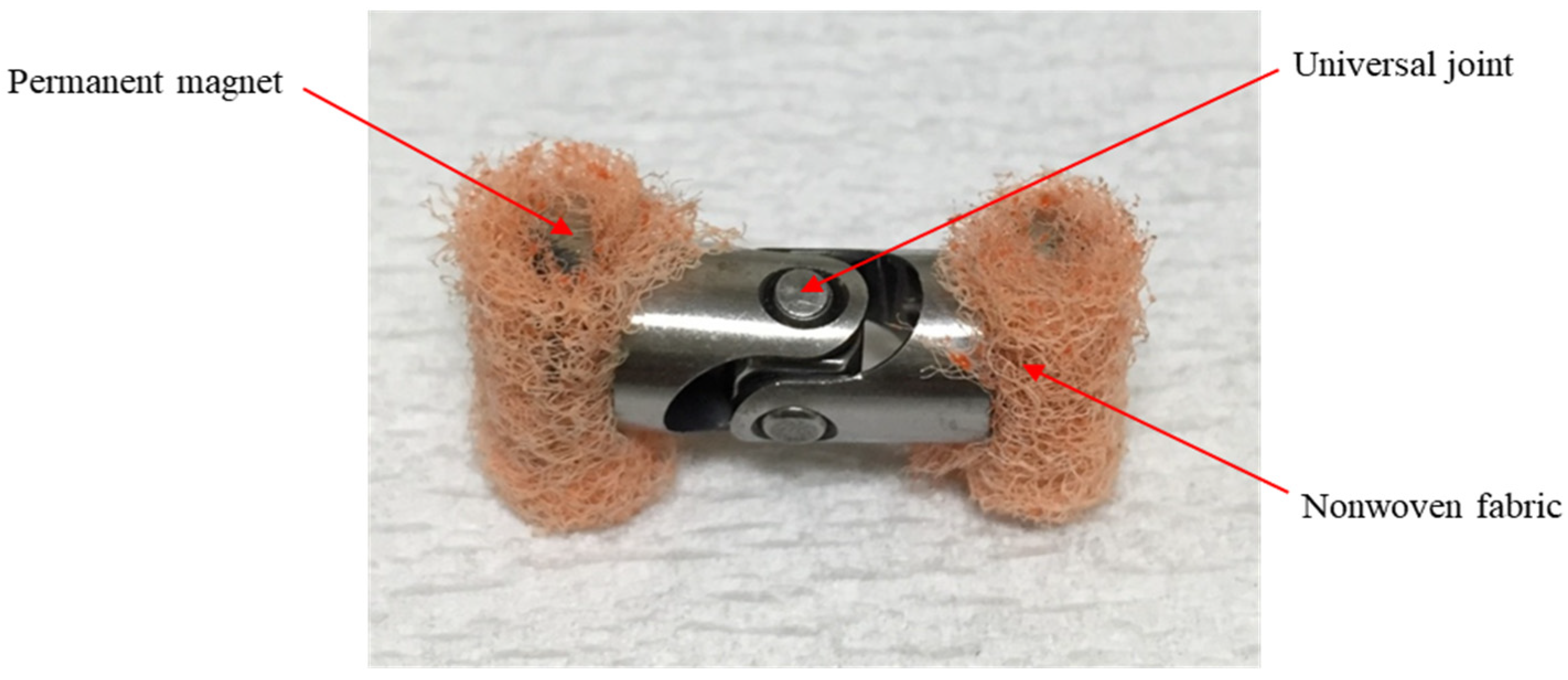
| Magnetic machining tool | S45C carbon steel universal joint (Ø8 × Ø4 × 16 mm); Rare earth Nd-Fe-B permanent magnet (9 × 7 × 3 mm); Nonwoven Fabric (#3000) |
| Polishing fluid | 0.6 mL |
| Finishing time | 60 min (Measured every 10 min) |
| Working gap | 4 mm |
| Revolution | 360 min−1 |
| Total usage of mixed magnetic abrasive | Condition 1: Electrolytic iron particles (330 μm in mean dia): 0.4 g KMX magnetic abrasives (80 μm in mean dia): 0.2 g |
| Condition 2: Electrolytic iron particles (330 μm in mean dia): 0.24 g KMX magnetic abrasives (80 μm in mean dia): 0.12 g | |
| Condition 3: Electrolytic iron particles (330 μm in mean dia): 0.56 g KMX magnetic abrasives (80 μm in mean dia): 0.28 g |
| Mixed magnetic particles | Electrolytic iron particles (330 μm in mean dia): 0.4 g KMX magnetic abrasives (80 μm in mean dia): 0.2 g |
| Revolution | 360 min−1 |
| Working gap | Condition 1: 3 mm |
| Condition 2: 4 mm | |
| Condition 3: 5 mm |
| Working gap | 3 mm |
| Mixed magnetic particles | Electrolytic iron particles (330 μm in mean dia): 0.4 g KMX magnetic abrasives (80 μm in mean dia): 0.2 g |
| Revolution | Condition 1: 240 min−1 |
| Condition 2: 360 min−1 | |
| Condition 3: 480 min−1 |
| Working gap | 3 mm |
| Revolution | 360 min−1 |
| Combinations of abrasives with different particle sizes | Condition 1: Electrolytic iron particles (330 μm in mean dia): 0.4 g KMX magnetic abrasives (80 μm in mean dia): 0.2 g |
| Condition 2: Electrolytic iron particles (149μm in mean dia): 0.4 g KMX magnetic abrasives (80 μm in mean dia): 0.2 g | |
| Condition 3: 1 step: Electrolytic iron particles (330 μm in mean dia): 0.4 g KMX magnetic abrasives (80 μm in mean dia): 0.2 g 2 step: Electrolytic iron particles (149 μm in mean dia): 0.4 g KMX magnetic abrasives (80 μm in mean dia): 0.2 g |
| Workpiece | SUS304 stainless steel 90 degrees bent tube (Ø27.2 × Ø23.9 mm, L1 120 mm, L2 36 mm, R 38.1 mm) |
| Finishing length | 70 mm |
| Revolution | 360 min−1 |
| Mixed magnetic particles | Electrolytic iron particles (75 μm in mean dia): 0.4 g KMX magnetic abrasives (30 μm in mean dia): 0.2 g |
| Magnetic machining tool | S45C carbon steel universal joint (Ø8 × Ø4 × 16 mm); Rare earth Nd-Fe-B permanent magnet (9 × 7 × 3 mm); Nonwoven Fabric (#3000) |
| Polishing fluid | 0.6 mL |
| Finishing time | 60 min (Measured every 10 min) |
| Feeding speed | 40 mm/min |
| Working gap | Condition 1: 3 mm |
| Condition 2: 4 mm | |
| Condition 3: 5 mm |
| Working gap | 4 mm |
| Feeding speed | Condition 1: 20 mm/min |
| Condition 2: 40 mm/min | |
| Condition 3: 80 mm/min |
| Workpiece | SUS304 stainless steel 90 degrees bent tube (Ø27.2 × Ø23.9 mm, L1 120 mm, L2 36 mm, R 38.1 mm) |
| Finishing length | 70 mm |
| Feeding speed | 20 mm/min |
| Revolution | 360 min−1 |
| Magnetic machining tool | S45C carbon steel universal joint (Ø8 × Ø4 × 16 mm); Rare earth Nd-Fe-B permanent magnet (9 × 7 × 3 mm); Nonwoven Fabric (#3000) |
| Working gap | 4 mm |
| Finishing time | 90 min (Measured every 10 min) |
| Mixed magnetic particles | 1 step: Electrolytic iron particles (330 μm in mean dia) Abrasive slurry of #1200WA (7.5wt%): 4 mL 2 step: Electrolytic iron particles (330 μm in mean dia) Abrasive slurry of #4000WA (7.5wt%): 4 mL 3 step: Electrolytic iron particles (149 μm in mean dia) Abrasive slurry of #10000WA (7.5wt%): 4 mL 4 step: Electrolytic iron particles (75 μm in mean dia) Abrasive slurry of #30000WA (7.5wt%): 4 mL |
| Total supply quantity of mixed magnetic abrasive | Condition 1: 0.4 g |
| Condition 2: 0.6 g | |
| Condition 3: 0.8 g |
Disclaimer/Publisher’s Note: The statements, opinions and data contained in all publications are solely those of the individual author(s) and contributor(s) and not of MDPI and/or the editor(s). MDPI and/or the editor(s) disclaim responsibility for any injury to people or property resulting from any ideas, methods, instructions or products referred to in the content. |
© 2023 by the authors. Licensee MDPI, Basel, Switzerland. This article is an open access article distributed under the terms and conditions of the Creative Commons Attribution (CC BY) license (https://creativecommons.org/licenses/by/4.0/).
Share and Cite
Zhou, Z.; Sun, X.; Yang, Y.; Fu, Y. A Study on Using Magnetic Abrasive Finishing with a 6-Axis Robot to Polish the Internal Surface Finishing of Curved Tubes. Coatings 2023, 13, 1179. https://doi.org/10.3390/coatings13071179
Zhou Z, Sun X, Yang Y, Fu Y. A Study on Using Magnetic Abrasive Finishing with a 6-Axis Robot to Polish the Internal Surface Finishing of Curved Tubes. Coatings. 2023; 13(7):1179. https://doi.org/10.3390/coatings13071179
Chicago/Turabian StyleZhou, Zhenfeng, Xu Sun, Yanzhen Yang, and Yongjian Fu. 2023. "A Study on Using Magnetic Abrasive Finishing with a 6-Axis Robot to Polish the Internal Surface Finishing of Curved Tubes" Coatings 13, no. 7: 1179. https://doi.org/10.3390/coatings13071179