Review

Printability of (Quasi-)Solid Polysiloxane Electrolytes for Online Dye-Sensitized Solar Cell Fabrication

1
GREENMAT, CESAM Research Unit, Department of Chemistry, University of Liège, 4000 Liège, Belgium
2
IM2NP, UMR 7334 CNRS, Campus de Chateau-Gombert, Aix-Marseille Université, Université de Toulon, 13453 Marseille, France
*
Authors to whom correspondence should be addressed.
Coatings 2023, 13(7), 1164; https://doi.org/10.3390/coatings13071164
Submission received: 21 May 2023 / Revised: 19 June 2023 / Accepted: 22 June 2023 / Published: 27 June 2023

Abstract

:
Dye-sensitized solar cells (DSSCs) are a very promising solution as remote sustainable low power sources for portable electronics and Internet of Things (IoT) applications due to their room-temperature and low-cost fabrication, as well as their high efficiency under artificial light. In addition, new achievements in developing semitransparent devices are driving interest in their implementation in the building sector. However, the main obstacle towards the large-scale exploitation of DSSCs mainly concerns their limited long-term stability triggered by the use of liquid electrolytes. Moreover, the device processing generally involves using a thick adhesive separator layer and vacuum filling or injection of the liquid polymer electrolyte between the two electrodes, a method that is difficult to scale up. This review summarizes the advances made in the design of alternative (quasi-)solid polymer electrolytes, with a focus on polysiloxane-based poly(ionic liquid)s. Their behavior in full DSSCs is presented and compared in terms of power generation maximization, advantages and shortcomings of the different device assembly strategies, as well as polymer electrolyte-related processing limitations. Finally, a fair part of the manuscript is allocated to the assessment of liquid and gel polymer electrolyte printability, particularly focusing on polysiloxane-based electrolytes. Spray, blade (slot-dye), screen and inkjet printing technologies are envisaged considering the polymer electrolyte thermophysical and rheological properties, as well as DSSC processing and operating conditions.

1. Introduction

The worldwide power consumption is expected to increase by 47% in the next 30 years due to population and economic growth [1]. Hence, there is a growing interest in renewable energy sources and, more precisely, solar energy, which is readily available and abundant. Apart from the abundance of potentially exploitable solar energy, photovoltaic (PV) cells have competitive maintenance costs and can operate silently off-grid, making them ideal for usage on remote sites or mobile applications. According to Greenpeace International, solar PV cells could provide 14% of total electricity generation by 2030 and employ 10.3 million people [2]. More than 80% of the PV market for terrestrial applications is currently dominated by mono- and polycrystalline (c-Si) bulk silicon solar cells, which offer the best compromise between cost and performance. To date, this is the most mature PV technology with terrestrial cell efficiencies between 12% and 25% [3]. However, although silicon is abundant, a consequent energy budget is consumed for silicon purification [4]. Furthermore, recycling is not easy as lower Si grades are obtained but further powder engineering can allow its exploitation in other energy-related domains such as batteries [5,6].
Beside bulk silicon solar cells, a second generation of thin film PV devices has been developed, which includes amorphous Si, CdS, CdTe, CuInSe2 (CIS), CuInGaSe2 (CIGS) and Cu2ZnSnS4 (CZTS) [7,8]. Thin-film technology has always been cheaper but less efficient than conventional c-Si technology. Terrestrial cell efficiencies between 7% and 21% have been established [3,7], but their large-scale exploitation has been hindered by the high toxicity of constituent materials.
Apart from their lower fabrication cost, third-generation solar cells, including perovskite solar cells, organic solar cells and dye-sensitized solar cells, are appealing nowadays for their tunable color/transparency and the flexible substrate-compatible deposition processes [9].
Record efficiencies of up to 25.7% at lab scale were reported for perovskite solar cells [10], which still remain environmentally hazardous due to their content in toxic lead and saltlike minerals, and are unstable when exposed to air moisture [11].
After more than 20 years of research, a new generation of dye-sensitized solar cells (DSSCs) emerged on the PV market [12], striving to level Si-based technology and to target greener processing technologies. Since the first report of O’Regan and Grätzel in 1991 on DSSCs based on liquid electrolytes with the standard I / I 3 mediator and a Ru complex as sensitizer reporting modest performances [13], the technology has come a long way and performance has doubled. The introduction of new redox couples based on Co-complexes and porphyrin dyes contributed to achieving the benchmark value of 14.7% [14]. Indeed, cobalt or copper complex redox mediators have a more positive redox potential and thus enable a higher theoretical maximum photovoltage [15,16,17,18]. Recently, that benchmark was overpassed with 15.2% efficiency being reported for Co-cosensitized DSSCs for which the TiO2 photoanode was preconditioned with hydroxamic acid [19]. Although the power conversion efficiency of DSSCs is not as good as that of perovskite or organic solar cells in outdoor sunlight conditions, they outperform them under indoor artificial illumination [20], with a 34.5% efficiency record reported [21] for cells comprising Cu-redox mediator-based liquid electrolytes. DSSCs can therefore be a solution to the increasing demand for portable and indoor power generation as reflected by the current trends of the indoor photovoltaic market, which was predicted to reach 109 USD in 2021 [21]. However, fulfilling that challenge is not straightforward due to the rather slow progression of DSSC efficiency over the last decade, as illustrated in Figure 1 [20,21,22,23,24,25,26,27,28,29,30,31,32,33,34,35,36].
In addition to their outstanding indoor performance, DSSCs manufacturing mostly involves normal atmosphere chemical processes with few limitations on materials availability. DSSCs are nearly temperature-independent in the normal operating temperature range of 20–70 °C, being able to radiate heat away much more efficiently than traditional silicon cells [37].
So far, the main obstacles towards the emerging of the DSSC technology in the PV market are electrolyte-related instability issues and tedious multistep cell assembly procedures that will be discussed in detail below with a focus on current polymer electrolyte recipes and deposition method trends. Indeed, indoor and outdoor applications of DSSCs based on liquid electrolytes are limited due to some practical problems, such as leakage and volatilization of solvent, photodegradation and desorption of dye and counter electrode corrosion [38].
A significant number of reviews and publications summarize the advances made in preparing gel or (quasi-)solidlike polymer electrolytes and their use implementation in DSSCs while principally using injection or vacuum filling during mounting. None or few reports [39,40,41] analyze the thermophysical and rheological properties of the polymer electrolytes with the goal of applying them through scalable spray or printing processes and fitting the different device designs. This review particularly addresses these issues with a focus on a new and less-studied class of polymer electrolytes for DSSCs, the polysiloxanes.
As further developed in this review, polysiloxane-based electrolytes have great potential of exploitation by DSSCs due to their thermal and chemical resistance and their high compatibility with common electrolyte additives (ionic liquids, low/high boiling point solvents, fillers or other polymers) used for tuning the ink rheology for printing.

2. DSSC Operation and Configuration
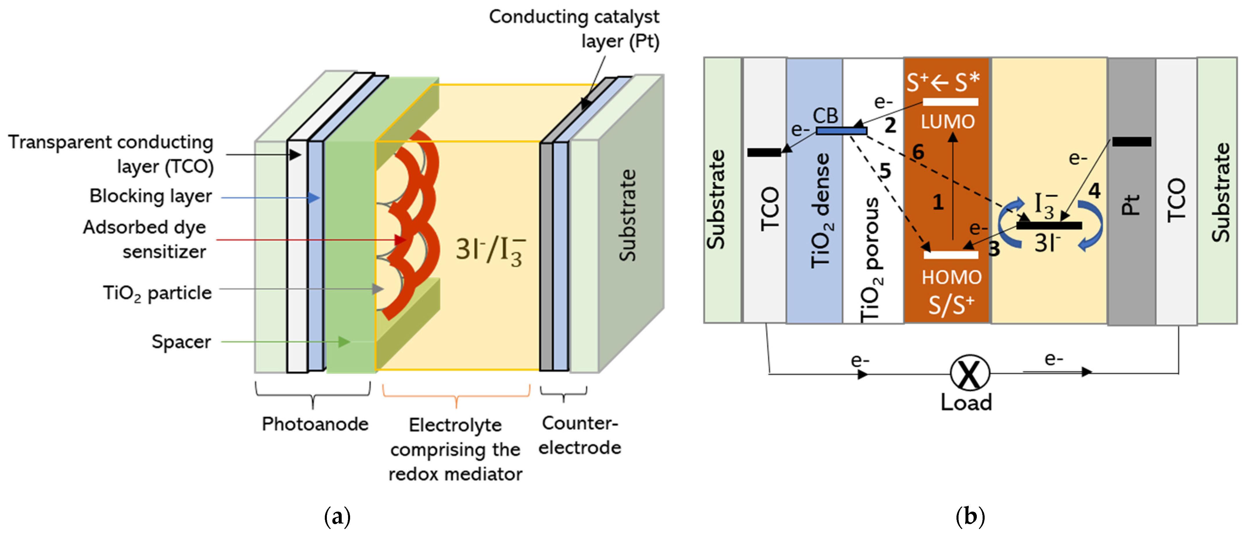
2.1. DSSC Operation

A DSSC is a photoelectrochemical device in which several electron transfer processes run in parallel and in competition. In contrast to the semiconductor p-n junction solar cells, where light absorption and charge transport occur in the same material, the DSSC separates these functions: photons are absorbed by the dye molecules and photogenerated charges are transported through the photoanode and electrolyte. In DSSCs, the photoanode is a mesoporous semiconducting oxide layer, usually TiO2, composed of nanometer-sized particles deposited on a transparent conductive substrate and sintered to allow the electronic conduction (Figure 2a). A monolayer of dye-sensitizer (S) molecules is attached to the surface of the oxide. The counter electrode (CE) is composed of a thin catalyst layer, typically Pt or C, deposited on a conducting substrate (Figure 2a). A redox electrolyte allows the transport of electrical charges between the dye-sensitized photoanode and the CE, thus closing the cycle. Upon light absorption, the dye (S) wrapping the TiO2 particles is excited to a higher energy state S* (reaction 1 and Figure 2b). Through electrons transfer, the dye is oxidized, whereas the electrons are transferred to the conduction band (CB) of the photoanode semiconductor (reaction 2 and Figure 2b). The electrons diffuse across the semiconductor toward the external circuit and reach the counter electrode where they react with the electrolyte that fills the space between the two electrodes (Figure 2a). The original state of the oxidized dye is subsequently restored by electron acceptance from the reduced redox couple (I) in the electrolyte (reaction 3 and Figure 2b), which is itself regenerated at the platinum counter electrode (reaction 4 and Figure 2b) by reduction of the triiodide ( I 3 ) [42,43,44,45]. In addition to the forward electron transfer and ionic transport processes, several competing electron recombination pathways evolve at the same time: the recombination of the injected electrons with the dye cations (reaction 5 and Figure 2b) or the recombination of the injected electrons with the triiodide redox mediator (reaction 6 and Figure 2b).
(1)
S + hv → S*
(2)
S* → S+ + e
(3)
S+ + 3/2 I → 1/2 I 3 + S
(4)
I 3 + 2eCE → 3 I
(5)
S+ + eCB → S
(6)
I 3 + 2eCB → 3 I
The overall sunlight-to-electric power conversion efficiency (PCE) of DSSC (ɳ) is defined by the potential difference between the semiconductor Fermi energy and the redox potential of the electrolyte mediator (the open-circuit potential—VOC) and calculated from Equation (1):
ɳ = Pmax/Pin = JscVocFF/Pin
where Pmax is the maximum obtainable power, Pin is the incident light intensity, Jsc is the photocurrent for zero potential, Voc is the photovoltage measured at open circuit, and FF is the fill factor. The fill factor ranges from 0 to 1. It reflects the parasitic electrochemical and electrical losses in the cell and is easily noticeable as a deviation from an ideal rectifying I–V behavior (Figure 3).
The ratio of the produced monochromatic photocurrent (Jsc in mA/cm2) and the corresponding incident wavelength photon flux (Pin in mW/cm2) as a function of wavelength (λ in m) is named incident photon-to-current efficiency (IPCE) (Equation (2)) and literally predicts the PCE evolution [46].
I P C E = 1240 × J s c / λ P i n
For better comparison, the cell efficiency parameters are referenced to a standard 1000 sun (W/m2) incident radiation, under standardized air mass coefficient AM1.5.

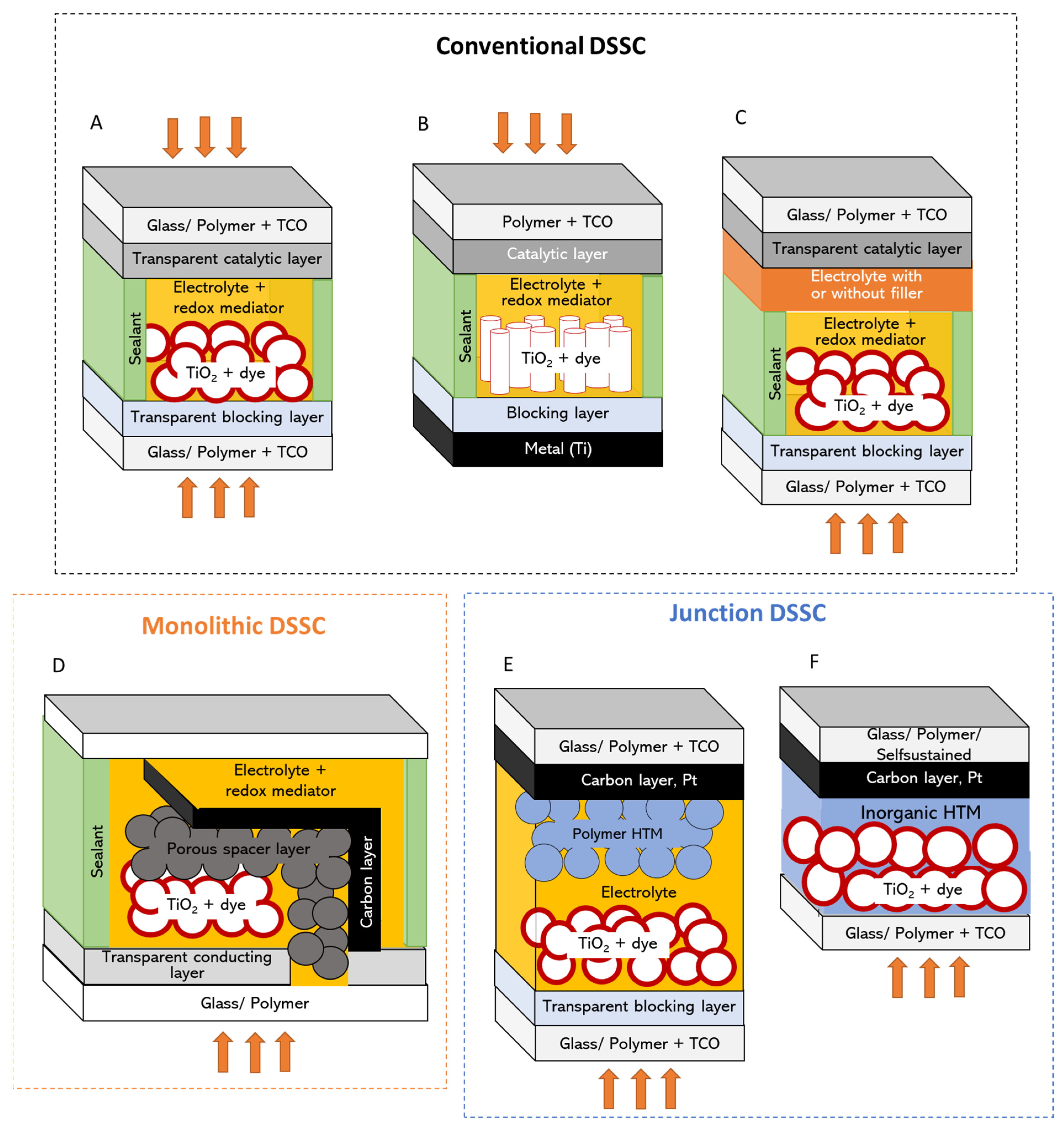
2.2. DSSC Configuration
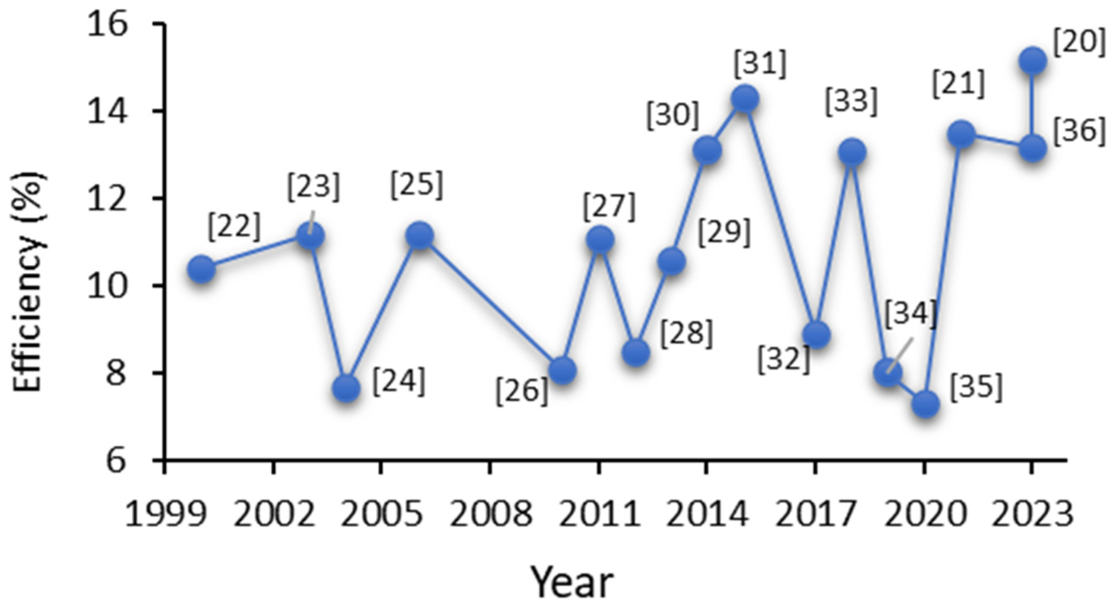
As illustrated in Figure 2, DSSCs are generally sandwich-type structures with different configurations depending on the type of materials used, with the substrate characteristics (e.g., flexibility, conductivity, optical properties, etc.) having a major impact on the configuration choice and on the components’ preparation methods.
Conventionally rigid glass substrates were used for building DSSCs with a bifacial configuration [47,48] (Configuration A in Figure 4). In addition to the good oxygen and moisture impermeability and chemical inertness, the glass substrate can support harsh processing conditions as required for the TiO2 layer fabrication, from solutions or suspensions by spin-coating, dip-coating or blade-coating [49,50,51]. Indeed, the high temperature annealing of the TiO2 layer is necessary to remove the solvents and the organic binders present in the solution but also to sinter the particles together in the benefit the charge transfer process. When these devices are front illuminated, the incoming radiation first meets the transparent conductive glass substrate (e.g., the fl-uorine-doped tin oxide—FTO), which is covered by the semitransparent TiO2 photoanode impregnated with the dye. The absorption of radiation related to the FTO is negligible. These devices can also operate in a reverse-illumination configuration provided a transparent counter electrode is used, but less efficiently [47,52] due to light absorption by the counter electrode and the electrolyte before reaching the photoactive dye. The rigid configurations are those holding record efficiencies exceeding 13% [14,53], although they are still based on liquid electrolytes comprising volatile solvents such as acetonitrile and 3-methoxypropionitrile (Table 1). Unsurprisingly, these devices suffer from the well-known liquid electrolyte-related stability issues. Moreover, liquid electrolytes are vacuum filled between the electrodes, a bottleneck process with regard to industrial mass production.
The ambition to constantly make the photovoltaic technology evolve, particularly with a view to adapting it to increasingly complex architectural constraints, has also driven the interest in lightweight and cheap substrates, such as polymer substrates or metal foils [49,52,54], which are compatible with roll-to-roll processes, essential for moving toward mass production and blending with the building environment. The window electrode of a flexible DSSC is usually made of indium tin oxide (ITO)-coated polyethylene terephthalate (PET) or polyethylene naphthalene (PEN) [55,56,57]. Likewise, self-supported electrodes such as titanium foil [58,59,60] are also used (Table 1). The counter electrode catalyst layer based on Pt, carbon nanotubes, graphene or carbon black are supported either on the same type of polymer substrates or metal substrates such as steel, graphite or titanium foils [52,56,57,61,62]. If a metallic substrate is used to support the dye-sensitized TiO2 photoelectrode, back illumination (configuration B in Figure 4) is required for device operation [27]. As opposed to glass, plastic substrates have high moisture transmission rates [62] and extra encapsulation methods are required for securing device stability [63,64,65]. In addition, low temperature chemical methods have to be applied for TiO2 synthesis (pressing, UV laser sintering, microwave radiation, electrodeposition, hydrothermal growth [51,56,57,66], which most often leads to less adherent electrodes with poor charge transport efficiency. Physically deposited TiO2 photoanodes have been tested as alternatives [67] but their performance is still limited due to the reduced specific surface and the high film reflectivity. The plastic substrates are also sensible to the harsh organic solvents usually used in the composition of liquid electrolytes, such as acetonitrile (ACN) or valeronitrile (VN) [49]. Thus, using flexible configuration comes with several challenges.
For flexible devices fabrication, the titanium foil substrate remained the first choice for high-temperature TiO2 photoanode processing due to its suitable chemical and thermal stability. Metal foil-supported TiO2 photoanodes combined with plastic counter electrodes are the key solution for developing highly efficient, fully flexible DSSCs by using a single, online and up-scalable printing process.
As for the rigid substrates, liquid electrolytes are mostly used in flexible devices. Glass–glass encapsulations (by using either thermoplastic or glass frit-based sealings), glass–plastic or all-plastic specific sealing procedures are adopted for the different DSSC designs to achieve notable stability under natural and simulated environmental conditions [68]. Apart from electrolyte leakage and evaporation, sensitizer photodegradation and counter electrode corrosion have to be addressed as well. Finally, there is a high risk of electrodes short-circuiting while bending the liquid flexible devices.
To address these issues, gel or solid-state polymer electrolytes have been proposed for DSSC [17,69,70]. In the case of gel electrolytes, the electrolyte is trapped inside the physically (temperature, photoinitiation) or chemically (inorganic—SiO2, TiO2 and organic gelators–polymers) crosslinked polymer matrix, thus inhibiting its evaporation. The use of polymer gel electrolytes has opened up the path to other, more scalable deposition and cell assembly procedures. The polymer gel is typically screen-printed on the photoanode, then the counter electrode is pressed over and polymer crosslinking occurs at room temperature, RT [71,72], through heating [73], cooling [74] or UV-curing [75] (Table 1). Recently, I-Ping Liu et al. [41] reported a double-layered electrolyte DSSC configuration (Configuration C in Figure 4) where the gel electrolyte is coated on both electrodes before device lamination, reaching 8.5% efficiency under artificial light due to the improved contact between the electrolyte and the counter electrode. Vacuum filling was also used [76] for polysiloxane gel electrolytes, proving remarkable efficiency long-term stability, which in this particular case was also related to the use of an iodine-free electrolyte. It is worth mentioning that the electrolyte/electrode interfacial contact and ion diffusion properties are determined by the small liquid quantity present in the gel composition and, therefore, a suitable sealing of the device is required to prevent excessive drying.
In parallel, solid-state electrolytes have been developed [77,78,79] (Table 1), showing, however, lower efficiencies due to limited electrolyte penetration into the (meso)porous TiO2 and reduced ionic conductivity. The polymer crosslinking is achieved through ambient soaking or hot pressing and efficiencies similar to quasi-solid-state devices have been achieved.
Table 1. Summary of the best performing DSSCs as a function of configuration and type of substrate. The electrolyte composition, nature (liquid, gel or solid) and deposition methods are emphasized in particular. Please consult corresponding references for acronym definitions.
Type of DevicePhotoelectrodeCounter ElectrodeElectrolyteElectrolyte Deposition Type of IlluminationEfficiency (%)StabilityRef.
Conventional liquid devicesHigh temperature porous TiO2 screen-printed on FTO glass PEDOT electrochemically polymerized onto FTO glass0.16 M [Cu(I)(tmby)2] TFSI and 0.08 M [Cu(II)(tmby)2] (TFSI)2 along with 0.1 M NaTFSI and 0.45 M NMP in ACNVacuum fillingFront illuminated15.21000 h at 1000 lux LED[19]
High temperature porous TiO2 screen-printed on FTO glass with scattering layerGraphene nanoplatelets of Au/FTO glass0.20 M [Co2+(phen)3] (PF6)2, 0.05 M [Co3+(phen)3](PF6)3, 0.07 M LiClO4, 0.02 M NaClO4, 0.03 M TBAPF, 0.01 M TBPPF, 0.01 M HMImPF, 0.30 M TBP, 0.1 M TMSP, 0.10 M MP, 0.05 M CPrBP, 0.1 M CPeBP, and 0.05 M COcBP in MeCNVacuum fillingFront illuminated14.3Not assessed[14]
High temperature porous TiO2 screen-printed on FTO glass with scattering layerGraphene drop casted on FTO glass0.25 M Co(bpy)3(TFSI)2, 0.06 M Co(bpy)3(TFSI)3, 0.1 M LiTFSI, and 0.5 M TBP in ACNVacuum fillingFront illuminated13.0500 h at 25 °C
1000 W m−2
[53]
TiO2 nanotubes by anodization on FTO glassPt-coated FTO (Solaronix)0.60 M BMIMI, 0.03 M I2, 0.1 M GTC in ACN/VN (85:15 vol%)Vacuum fillingFront illuminated10.224 h at RT[56]
TiO2 screen-printed on Ti foilPt spray coated on ITO-PEN0.6 M PMII, 0.03M I2, 0.06 M LiI 0.1 M GuSCN, and 0.05 M TBP in ACNVacuum fillingBack illuminated8.46Not assessed[58]
TiO2 screen-printed on ITO-PEN with scattering layerPt sputtered on ITO-PEN0.6 M 1,2-dimethyl-3-propylimidazolium, 0.05 M I2, 0.1 M LiI, iodide and 0.5M TBP in ACNVacuum fillingFront illuminated8.1Not assessed[26]
High temperature porous TiO2 screen-printed on FTO glassPt screen-printed on FTO glass0.6 M PMIMI, 0.03M I2, 0.06 M LiI 0.1 M GuSCN, and 0.05 M TBP in ACNVacuum fillingFront illuminated
Back illuminated
6.04
4.71
Not assessed[55]
TiO2 spray-coated on ITO-PEN and pressedCarbon black spray-coated on AgNWs-PEN10 mM LiI, 1 mM I2 and 0.1 M TBAMtfVacuum fillingFront illuminated5.9Not assessed[57]
Conventional quasi-solid devicesHigh temperature porous TiO2 screen-printed on FTO glass with scattering layerPEDOT electrodeposited on FTO glass0.1 M [Cu(I)(tmby)2] TFSI and 0.04 M [Cu(II)(tmby)2](TFSI)2 complexes with 0.1 M LiTFSI and 0.6 M NMB in ACNVacuum filling followed by UV curingFront illuminated13.51000 h at 45 °C 1000 W m−2[21]
High temperature porous TiO2 screen-printed on FTO glassPt sputtered on FTO glass0.1 M LiI, 0.6 M PMIMI, 0.05 M I2, 0.1 M GuSCN, 0.5 M TBP, and ACN + 20 wt.% P(VA-co-MMA) + 5% TiO2 fillerScreen printing and pressingFront illuminated9.41000 h at 30 °C[71]
High temperature porous TiO2 screen-printed on FTO glassPt drop-casted FTO glass0.53 g PEO, 0.2 g of LiI, 0.04 g I2 and 5% acetamide in ACN: PC (20:1, v/v)Screen printing and pressingFront illuminated9.01Not assessed[72]
High temperature porous TiO2 screen-printed on FTO glass with scattering layerPt sputtered on FTO glass0.1 M LiI, 50 mM I2, 0.8 M DMIMI, 0.5 M TBP, 0.1 N GuSCN in MPN + 9% PEO/PVDF + 4% TiO2Screen printing + hot pressing at 100 °CFront illuminated8.91500 h at 60 °C in dark[68]
High temperature porous TiO2 screen-printed on FTO glass with scattering layerPt sputtered on FTO glass0.1 M LiI, 50 mM I2, 0.8 M DMIMI, 0.5 M, tBP and 0.1 M GuSCN into a MPN solvent + 9 wt.% PEO/PVDF with 0.6 wt.% ZnOScreen-printed on both electrodesFront illuminated8.501200 h at RT[41]
High temperature porous TiO2 screen-printed on FTO glass with scattering layerPt drop-casted on FTO glassPS3 polysiloxane/ECVacuum fillingFront illuminated8.3>2000 h at RT[76]
TiO2 nanotubes by anodization on Ti foilPt sputtered on FTO glass0.6 M BMIMI, 0.0 1M I2, 0.1 M LiI 0.1 M GuSCN, and 0.5 M TBP in ACN + 7% PMMA-EAInjection filling than cooling at -4 °CBack illuminated7.11000 h at 52 °C[74]
Conventional solid-state devicesHigh temperature porous TiO2 screen-printed on FTO glass with scattering layerPt screen-printed on FTO0.6 M BMIMI, 0.03 M I2, 0.5 M TBP and 0.1 M GuSCN in ACN:VN (v/v, 85:15), 20 mol% MMA/HDDA crosslinked on the surface of dye-sensitized TiO2Dripping and RT soakingFront illuminated10.6580 h at RT[77]
TiO2 spray-coated on FTO glassPt-coated FTO glass0.4 g, EC, 0.2 g PC, 0.225 g PAN, 0.249 g 1-N-butyl-3-hexyl imidazolium iodide, 0.008 g I2 and carbon in ACN: THFHot pressingFront illuminated8.42Not assessed[79]
High temperature porous TiO2 screen-printed on FTO glassPEDOT spin-coated on the polyethylene separator0.6 M BMIMI, 0.03 M I2, 0.1 M GuSCN, and 0.5 M TBP in ACN: VN (v/v, 85:15)SoakingFront illuminated7.73Not assessed[78]
Monolithic
quasi-solid device
TiO2/ZrO2/C by screen printingGlass cover0.1 M LiI, 0.45 M NMBI, 0.4 M DMPIMI, 20 wt.% polymer in MeCNScreen printing and pressingFront illuminated6.97Not assessed[80]
Monolithic liquid deviceHigh temperature porous TiO2 screen-printed on FTO glass with scattering layer, ZrO2 spacer layer on topGraphite/carbon black on FTO glass0.165 M Co(II) and 0.045 M Co(III) tris(bipyridyl)tetracyanoborate complexes, 0.8–1.4 M TBP, and 0.1 M LiClO4Vacuum fillingFront illuminated9.5200 h at RT[81]
High temperature porous TiO2 screen-printed on FTO glass.CuFeS2 + carbon black drop casted on FTO glass0.6 M BMIMI, 0.03 M I2, 0.5 M TBP and 0.1 M GuSCN in ACNVacuum fillingFront illuminated8.05Not assessed[34]
Junction devicesHigh temperature porous TiO2 screen-printed on FTO glassPEDOT electrodeposited on FTO glass0.1 M [Cu(I)(tmby)2] TFSI and 0.04 M [Cu(II)(tmby)2](TFSI)2 complexes with 0.1 M LiTFSI and 0.6 M NMB in ACNVacuum fillingFront illuminated13.110 h at 45 °C
1000 W m−2
[33]
High temperature porous TiO2 screen-printed on FTO glass with scattering layerPt foilSolid state electrolyte HTM deposited on the photoelectrode by drop casting, CuIPressingFront illuminated10.1Not assessed[82]
High temperature porous TiO2 screen-printed on FTO glass with scattering layerPEDOT electrodeposited on FTO glassSolid state electrolyte HTM deposited on the photoelectrode, Cu(tmby)2] (TFSI)2 and [Cu(tmby)2](TFSI) 0.1 M LiTFSI and 0.6 M TBP in ACNVacuum filling and solvent evaporationFront illuminated11.71000 h at RT
1000 W m−2
[83]
A simplified version of the DSSC has been proposed to minimize the redox mediator diffusion path and simplify cell processing by coating both electrodes on the same substrate, leading to a monolithic structure as illustrated in configuration D in Figure 4. The counter electrode material is deposited on the previously dye-sensitized TiO2 covered by a porous separator layer to prevent short circuit, and afterward, the whole structure is flooded with the liquid electrolyte. However, monolithic DSSCs do not equalize the liquid devices performance [34,80,81] due to the higher charge transfer resistance at the spacer layer/counter electrode interface, spacer layer opacity and poor counter electrode reflectivity.
For all the above configurations, a 10 to 45 µm thick separator film [15,84] is used to avoid short-circuiting the electrodes, to define the thickness of the polymer electrolyte layer and also to prevent any leakage before electrolyte gelation or solidification. In case of monolithic devices, redox mediator diffusion path length and mass transport are governed by the thickness of the inorganic porous separator film. The separator extends the redox mediator diffusion path and can lead to a decrease in charge collection efficiency when the DSSC operates under highly intense illumination [33].
A new device design was proposed, which eliminates the need for a spacer layer and relies on using hole collecting materials as the counter electrode and redox mediator, a configuration known as junction DSSC (Configurations E and F in Figure 4). Inorganic (CuI, CuSCN) or organic (PEDOT, PANI, Spiro-OMeTAD) hole transporting materials, HTM [21,33,82,83], have notably been reported. Usually, the photoanode and hole-transporting layer are coated separately on the substrates and structure connection is performed by using a sealant and liquid electrolyte (Configuration E in Figure 4). A revolutionary solid-state cell design was proposed, which eliminates the sealant layer by coating the CuI or the amorphous Cu(I)/Cu(II) HTMs directly on the photoelectrode, just after dye sensitization (Configuration F in Figure 4) [82,83].
The same strategy was also reported for the fabrication of DSSCs based on spiro-MeOTAD as HTM [85]. However, this approach is not very practical because it requires long evaporation times and it is difficult to control this process on a large scale. In addition, the HTM must be photoelectrochemically stable, a good hole conductor, processable with a photoanode/sensitizer compatible method and with a lower HOMO level than the dye.
DSSC upscaling relies, among other things, on polymer optimization for better performance (ideal ionic conductivity, suitable viscosity for electrode penetration, transparency, thermal stability) and facile device assembly (suitable properties for printing and wet film hardening adapted to electrodes nature). Screen printing is the most reported method for the photoanode fabrication on polymer, metal or glass substrates [15,51]. Inkjet printing was successfully tested for depositing TiO2 photoanodes and for the photosensitization step where a fine spatial control over the dye loading was proven [86]. In addition, printing technologies have proven their effectiveness for carbon-based and conductive polymer-based counter electrode fabrication [49,87,88].
Besides stability, color and transparency are two important design criteria for DSSC building integration. The optical properties of DSSCs can be modified by tuning several parameters such as the dye, the electrolyte or the electrodes thicknesses [89,90,91]. Referring to the electrolyte, which is the main scope of our review, most devices contain iodine, which not only affects durability [92] but is also responsible for incident light absorption. Furthermore, the different I2 concentration in the electrolytes influence the charge transportation and electron recombination dynamics in DSSCs [93]. Thus, iodine-free polymer electrolytes have been developed [76,94], leading to remarkable performances in terms of efficiency and stability.
Efforts should be further focused on optimizing and developing new roll-to-roll printing-like processes (spray, blade, inkjet or screen printing) for the polymer layer deposition and device lamination without spacer.

3. Quasi-Solid and Solid-State Electrolytes

The electrolyte is a key component in the DSSCs, determining not only the performance of the cell but also its scalability. As such, the intrinsic electrolyte properties govern the charge and mass transfer processes in the cell but also the electrode compatible assembly method. In this section, we will focus on describing the state-of-the art polymer electrolytes and corresponding deposition methods.
Quasi-solid-state (semisolid-state) electrolytes (QSSEs) are presented as an alternative between solid and liquid states with synergetic properties from the two phases, i.e., the cohesive property of solid and the diffusive property of liquid with ionic conductivities reaching ~10−3 S cm−1 [95,96,97]. Although the efficiencies of the DSSCs with QSSEs are often lower than those of the DSSCs with liquid electrolytes (Table 1), they continue to be very promising, owing to their improved stability and better sealing ability.
QSSEs are divided into four main types: thermosetting [1], thermoplastic [98], composite [99], ionic liquid [100], and poly(ionic liquid) electrolytes [2]. This classification is based on the features, formation mechanisms and physical states of the electrolytes.

3.1. Thermosetting Polymer Electrolytes

Thermosetting gel electrolytes are prepared by soaking the synthesized copolymer in liquid electrolyte followed by thermo- [101,102,103,104] or photopolymerization [105,106,107] in situ. Table S1 in Supplementary Materials summarizes the latest achievements of thermosetting polymer electrolytes use in DSSCs.
All these electrolytes contain the iodine–iodide redox couple. In these electrolytes, the change is thermally irreversible. Despite having a solid-like appearance, they are classified as quasi-solid-state electrolytes because of the liquid phase [17] coexisting in the electrolyte.
Once hardened, these polymer electrolytes have exceptional thermal and chemical stability, making them ideal candidates for use in photovoltaic devices [108]. The greatest challenges when using UV-cured electrolytes lie in ensuring the UV inertness of the dye and the electrolyte ambient light stability while coating.

3.2. Thermoplastic Polymer Electrolytes

These electrolytes are prepared by mixing a polymeric matrix with a liquid electrolyte, which contains, apart from the redox mediator, ionic salts that boost the ionic conductivity [72,73,109,110,111,112]. Linear polymers are often used as matrix, including poly(ethylene oxide)—PEO, poly(acrylonitrile)—PAN, poly(vinyl pyrrolidinone)—PVP, polystyrene—PS, poly(vinyl chloride)—PVC, poly(vinylidene ester)—PVE, poly(vinylidene fluoride)—PVDF, poly(methyl methacrylate)—PMMA, etc. [113]. Many of these matrices have no solvation ability versus ionic species; thus, the ionic conduction is assumed by the ionic salts and redox mediator through the solvent, whereas the polymer governs the mechanical properties. This type of electrolyte can reversibly change from soluble state to a gel state or vice versa by controlling the temperature.
In order to manage the functional properties of the electrolyte, and in particular to reduce the viscosity, polymer blends were also tested including PEO/PVP, PEO/PAN, PEO–PVDF [72,113] or Poly (vinylidenefluoride-co-hexafluropropylene) (PVDF-HFP) [114].
Plasticizers [74], natural polymers [111,115,116] or inorganic fillers [41,73,117,118,119] are added to decrease the polymer–polymer chain interaction leading to improved ion mobility.
These electrolytes are easily mounted in devices by pressing the preformed gel sheets between the electrodes [72,111,120,121,122,123], but that does not always guarantee a proper interfacial contact with the photoanode. The vacuum-filled thermosetting electrolytes [109,119] are most likely richer in solvent.
Generally, compared to the DSSCs based on liquid electrolytes, the DSSCs assembled with polymer gel electrolytes have lower Jsc and higher Voc; the former is due to the lower mobility of redox couple components, and the latter is due to the suppression of dark current by polymer chains covering the surface of TiO2 electrode [124] and, thus, screening the electron recombination between the photoanode and the dye.

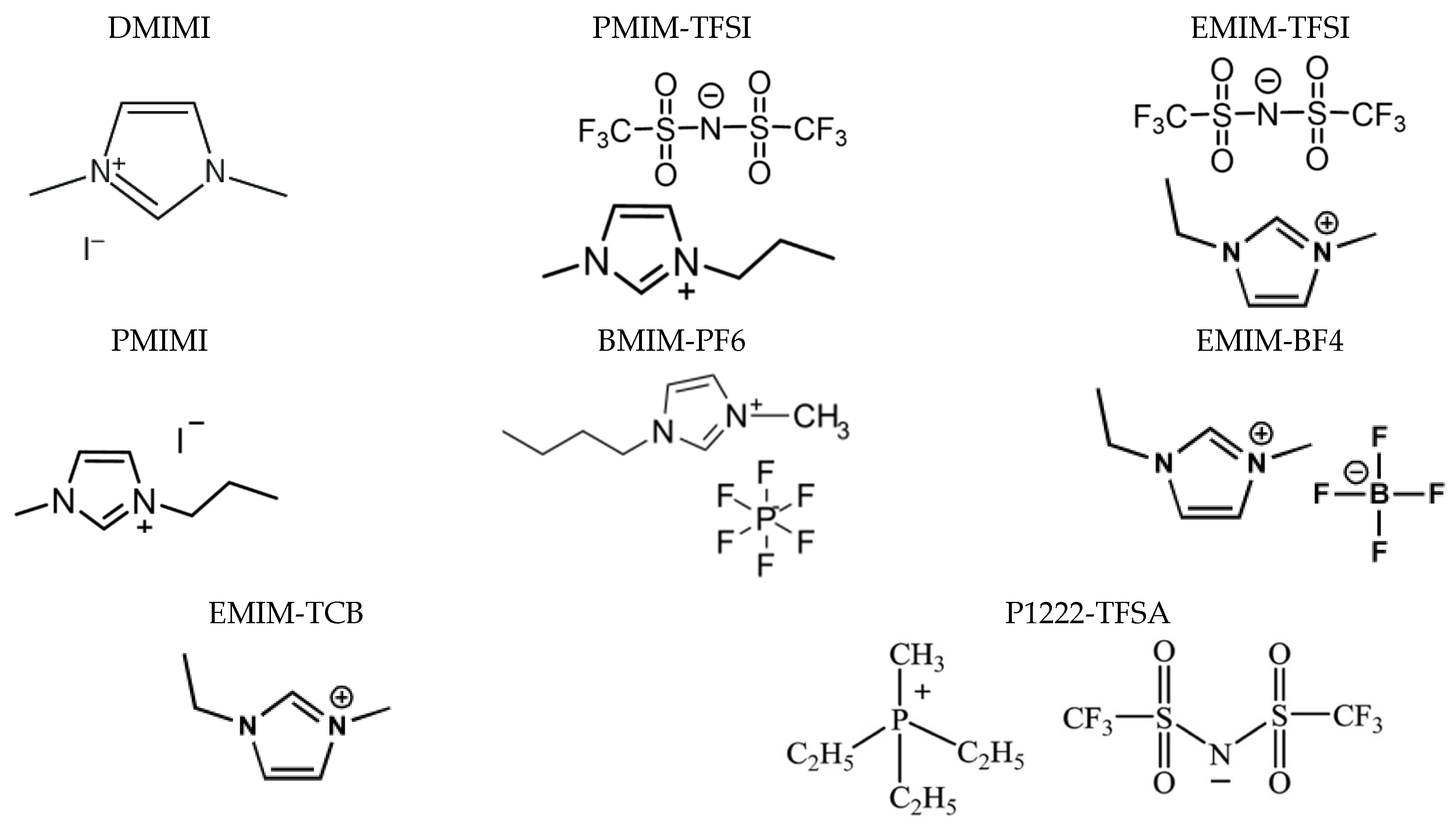
3.3. Ionic Liquid Electrolytes

Ionic liquids are molten salts at ambient conditions and are used as solvents in the preparation of liquid electrolytes as an alternative to highly volatile acetonitrile. They are also used as ionic conductors in DSSCs (Table S2 in Supplementary Materials) due to their higher chemical, electrochemical and thermal stability [17].
They are composed of an organic bulky cation and an anion (Figure 5) with ionic conductivity decreasing generally with the side-chain length [125,126]. Their physical properties can easily be tuned by modifying the ionic functionality [127] with important consequences for ion diffusivity and cell efficiency [125]. To confront the mass transport limitation observed for pure ionic liquids, highly viscous ionic liquids are often blended with less viscous ionic solvents as illustrated in Table S2 in Supplementary Materials. However, liquid state prevails and vacuum or injection filling remains the most used cell assembly approach, as for “classical” liquid electrolytes [31,125,128,129,130,131,132]. Adding polymers, dielectric solvents and/or inorganic fillers to ionic liquids turns them into gels [133] or solids [134,135], thus reducing the leakage risks and accessing other, more scalable, electrolyte deposition methods such as screen printing or (hot)pressing. Inorganic fillers, in addition to thickening the electrolyte mix, have an important role in enhancing the ionic mobility through the electrolyte gel/membrane by reducing the interaction between the polymer chains and blocking the iodide to interact with the TiO2 photoelectrode. Adding polymers also leads to a similar anticorrosion effect, which explains why polymer electrolytes have a slightly higher Voc than liquid ones [71,73,135,136]. However, lower Jsc is generally observed compared to liquid counterparts, owing to the low polymer electrolyte penetration into the TiO2 pores.
Most of these polymers are thixotropic, meaning their viscosity decreases with increasing share rate, which is ideal for printing process compatibility [41,73]. However, little progress is reported on flexible DSSCs based on this type of electrolyte, with all the devices presented in Table S2 in Supplementary Materials, being prepared on rigid substrates with a sealant in between, indicating the persistence of a liquid phase in the electrolyte after device assembly.

3.4. Composite Electrolytes

Composite polymer electrolytes (CPE) have been prepared by the addition of inorganic fillers such as TiO2 [71,73,134], ZnO [41], SiO2 [132], carbon derivates [137,138,139] or natural phylosilicate-based clays [140,141] in the polymer or ionic liquid-based electrolytes. The addition of such fillers permits improving the mechanical, interfacial and ionic conductivity properties of the polymer electrolytes.

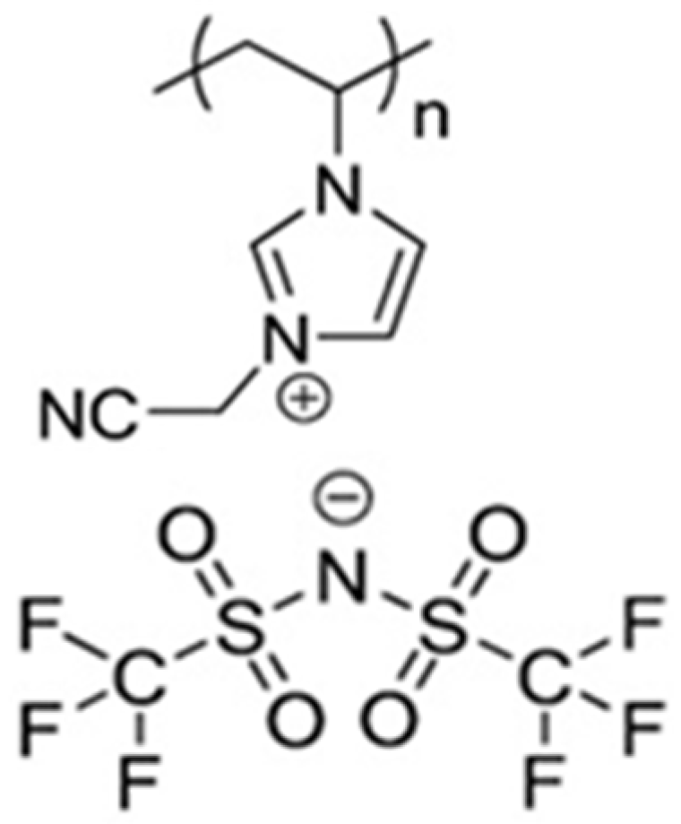
3.5. Poly(ionic liquids)

In recent years, polymeric ionic liquids or poly(ionic liquids) (PILs) have attracted growing attention as they combine both the novel properties of ionic liquids and improved mechanical durability and dimensional control of polymers, as shown in Figure 6 [142,143,144]. PILs are typically solid or viscous liquids, depending on their structure, glass transition temperature (Tg) and molecular weight. Although the cations are bound to the polymer, the redox species ( I and I 3 ) are mobile. The ionic liquid part of the PILs gives rise to a high ionic conductivity and tunable chemical structure and redox potential (Figure 6) [42,145]. Due to these unique properties, PILs are used as electrolytes in DSSCs in various forms: additives in liquid electrolytes [35,146], membranes [73,147,148], blends with well-matched ILs [102] or even in the pure form [149,150].
Table S3 in Supplementary Materials summarizes the best achievements in DSSCs with PIL-based electrolytes in liquid or (quasi-)solid-state form. None of the summarized liquid poly(ionic liquid) electrolytes were designed for printing, as they are generally used in their liquid form in the devices [102,151,152]. The few reported solid devices are based on electrolyte-swelled membranes [148] and device assembly is done via a separator.
Among poly(ionic liquids), a new category of polysiloxane-based electrolyte has emerged from the batteries field showing incredible potential for solid film preparation [153], which is further highlighted in Section 4.

4. Polysiloxane-Based Electrolytes

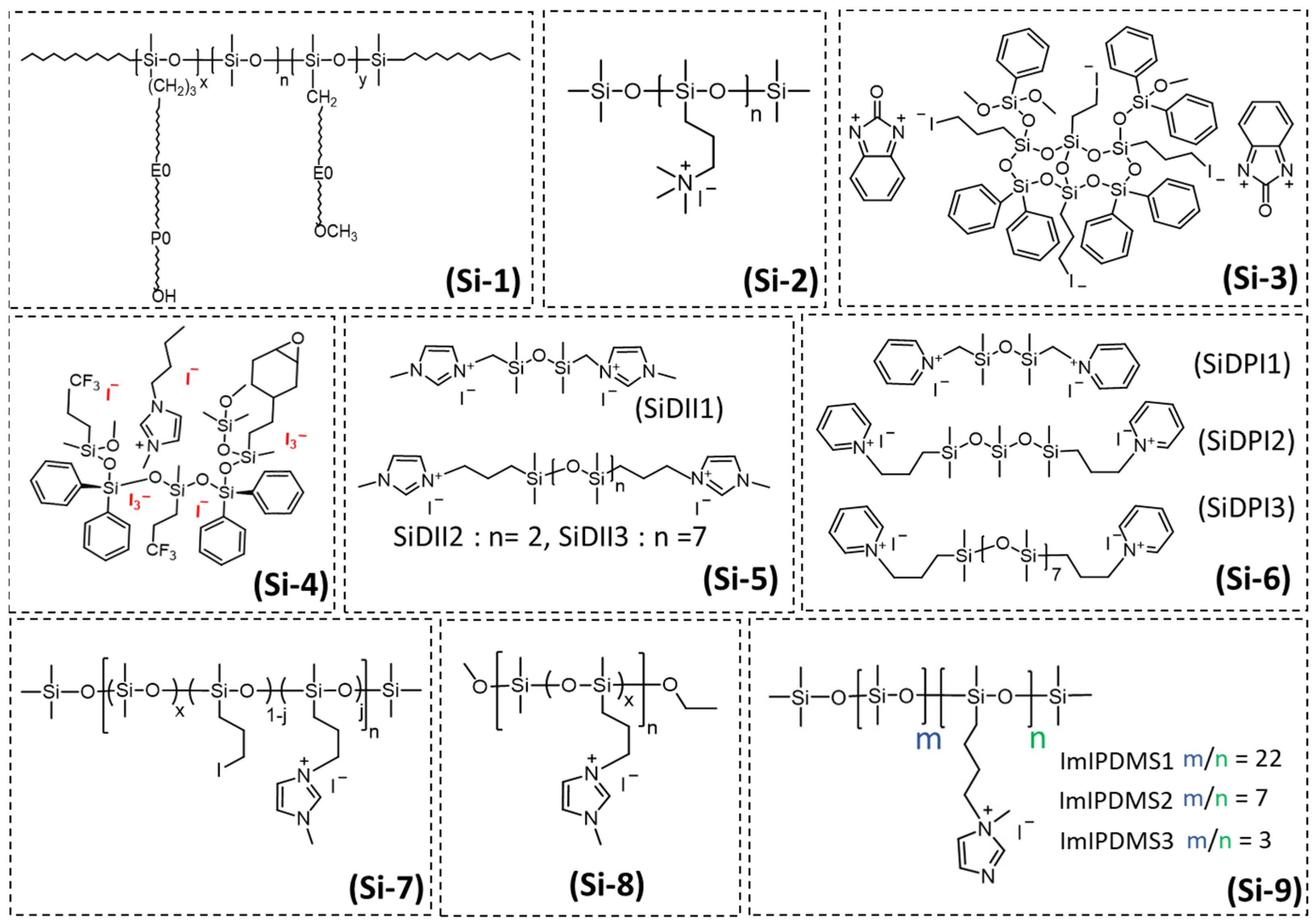
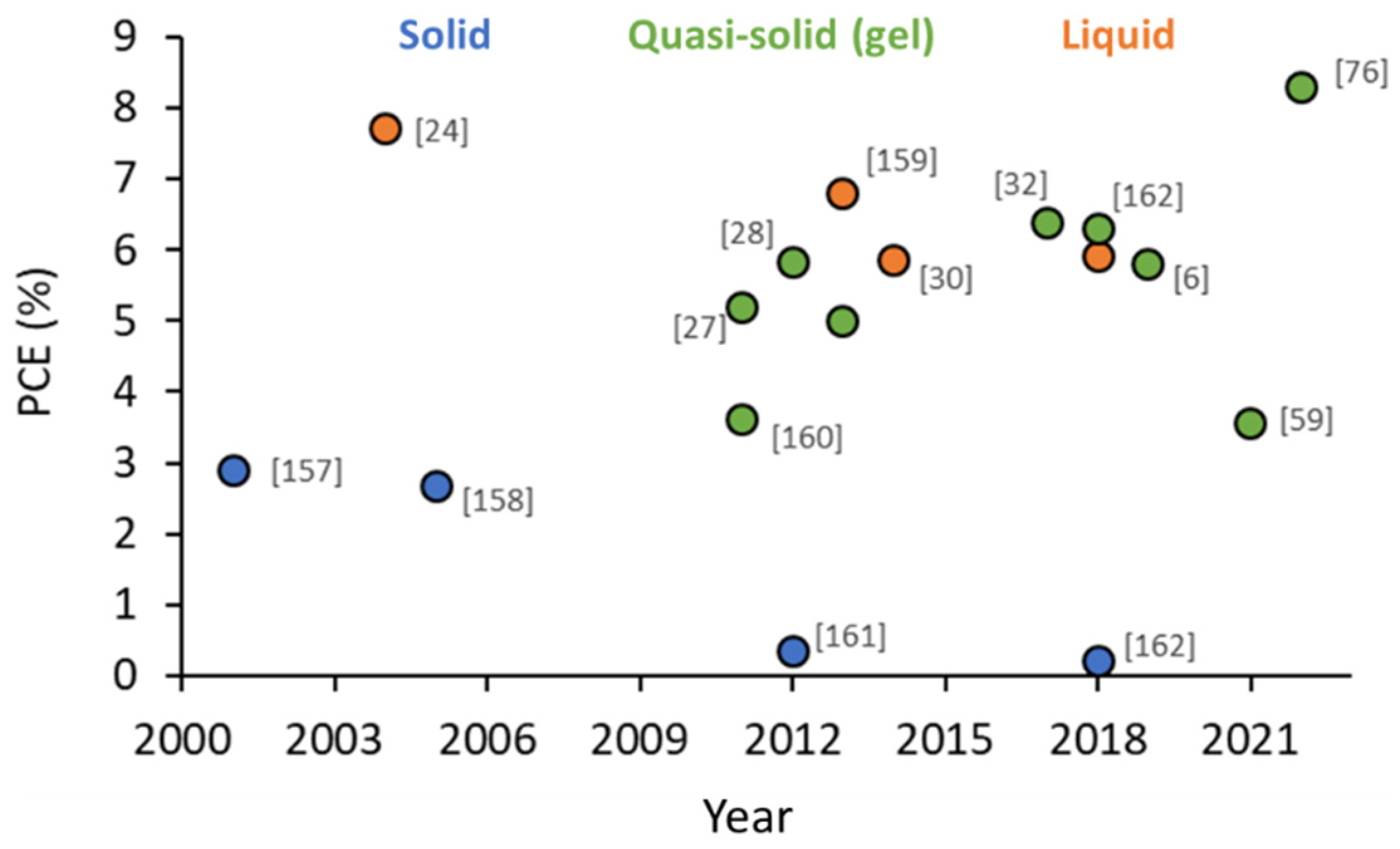
4.1. State-of-the-Art of Polysiloxane-Based Electrolytes in DSSCs

Although they have a slightly lower ionic conductivity than previously presented electrolytes (10−4–10−5 S/cm2), polysiloxane electrolytes are appealing for DSSC implementation as they present high chemical and thermal stability, as well as low toxicity [154].
As shown in Figure 7, along the years, different polysiloxanes have been prepared for DSSC application owing to their highly flexible backbone, with the barrier energy to bond rotation being only 0.8 kJ mol−1, as well as their very low Tg (−123 °C), high free volumes and polar side chains [155].
As for poly(ionic liquids), the nonpolar polymer backbone is bulky and determines the electrolyte viscosity and, consequently, the mass transport, whereas the ionic species move more or less freely among the siloxane chains, contributing to the ionic conductivity. The viscosity of polysiloxane increases linearly with the average molecular weight, branch content and branch length [156], as further detailed in Section 4.3.
In 2001, Ren et al. [157], introduced for the first time the use of polysiloxane-based electrolytes for DSSC applications. The novel electrolyte (Si-1 in Figure 7) was crosslinked with PEO chains. Briefly, polymethylhydrosiloxane precursor with Si-H and PEO (macromonomer) were mixed with LiI (20 wt.%), EC/PC (3:1, v:v) and a crosslinker and heated at 80 °C for 30 min. Then, I2 (5 wt.%) was added. The electrolyte was casted on the photoanode and joining with the Pt counter electrode was realized by in situ crosslinking at 60 °C. The energy conversion efficiency of the DSSC was very low, 2.9%, due to low ionic mobility (Table 2).
In 2004, a similar efficiency was reached (2.67%) for a polysiloxane electrolyte plasticized with 10% PAN [158]. Figure 8 displays the yearly evolution of the photovoltaic parameters for the polysiloxane-based electrolytes in liquid, quasi-solid or solid-state devices.
The lowest reported efficiencies for polysiloxane-based DSSCs were based on solid electrolytes or very viscous ones (Figure 8 and Table 2) with obvious limits in terms of mass and ionic transfer properties. At the opposite end, as expected, much higher efficiencies were reported for polysiloxane-based liquid-state DSSCs (Figure 8).
Much more development was realized for the quasi-solid (gel-like) electrolytes, with record efficiencies of 6.8% and 8.3% reported for iodine containing [158] and iodide-free [76] electrolytes (see Figure 8). Relying on their high flexibility in terms of side-chain grafting, several ways were explored for controlling viscosity and crosslinking.
As such, low viscosity ionic liquids [30,159,160,161,162] or polymer crosslinkers [157] were blended with the polysiloxane electrolytes to reduce polymer interchain interaction and facilitate ion percolation [163].
In 2004, polysiloxane containing quaternary ammonium group (Si-2 in Figure 7), I2 and 50 wt.% of EC/PC (8:2) (w/w) was used as an electrolyte. The ambient conductivity of this plasticized electrolyte reached up to 1.9 × 10⁻³ S cm−1 and the DSSC showed performances comparable to liquid electrolyte [24].
In 2011, Yang et al., grafted imidazolium iodide moieties to the polysiloxane by simply mixing TESPIm+I ionic liquid with tetraethoxysilane (TEOS) in ethanol in the presence of HCl [160]. It is the first report of polysiloxane electrolyte modification with ionic liquids for DSSC application. To obtain a membrane, the previously prepared composition was mixed with PVDF in a 2/1 weight proportion and an antisolvent. Membrane crosslinking was achieved by heating at 80 °C (Table 2). The membrane swelled with an iodide-based liquid electrolyte sandwiched between the photoanode and the counter electrode without a separator, but modest PCE values were reported (3.61%). The same year, Jung et al. [27] reached higher efficiencies, 5.2% (Table 2), for DSSC comprising a new ionic siloxane hybrid electrolyte. The iodide-oligosiloxane monomer was synthesized by a simple sol gel condensation of 3-iodopropyltrimethoxysilane and diphenylsilanediol and the membrane crosslinking was achieved through thermal excitation in the presence of 2-benzimidazolone (Si-3 in Figure 7). They concluded that both the composition and concentration of the oligosiloxane used in the electrolyte affect the performance of the DSSCs.
In 2012, Bae et al. [28] fabricated an oligosiloxane gel electrolyte by introducing a novel in situ gelation of the liquid electrolyte (Si-4 in Figure 7). The alkoxysilane monomers are capable of gelling the liquid electrolyte through a sol–gel reaction, resulting in an effective infiltration and contact. The DSSC showed reduced charge recombination and an improved PCE of 5.8% (Table 2) with long-term stability (1000 h at 50 °C).
Table 2. Best yearly reported photovoltaic parameters for the DSSCs (liquid, quasi-solid and solid) based on polysiloxane electrolytes. Please refer to corresponding references for electrolyte components abbreviation full description.
Electrolyte CompositionIonic Conductivity
(mS/cm)
Viscosity
(cPs)
Deposition MethodJsc
(mA cm−2)
Voc (V)FF
(%)
PCE
(%)
Ref.
Polymethylhydrosiloxane + PEO, 20 wt% LiI, EC/PC (3:1, v:v), 5 wt% I2 1.1 Blade-casting + pressing1.70.72692.90[157]
1 M PSQAS, 0.05 M I2, 50 wt% of EC/PC (8/2) (w/w)1.9--160.56507.70[24]
1 M PSQAS, 0.05 M I2, 50 wt% of EC/PC + 10% PAN2.97 Blade-casting + pressing7.50.63572.67[158]
Il-SiO2/PVDF (1:2) with 0.5 M NaI, 0.05 M I2, 0.1 TBP in PC: EC 4: 6 (w/w) 3.4-Pressing11.190.70503.61[160]
0.6 M ID33, 0.1 M LiI, 0.5 M TBP, 0.05 M I2 in MPN + BI--Injection + in situ curing 10.300.76685.20[27]
0.25 M ECTS, 0.75 M FTMS, 1.5 M DPSD, 0.7 M BMIMI, 0.14 M I2, 0.1 M LiI, 0.25 M TBP in MPN0.1915,700Injection filling + T polymerization10.90.79685.83[28]
PSEO+ 10% PMIMI, 0.5 M NH4I, 0.1 M TBAI, 0.5 M DMPII, 0.1 M LiI, 0.2 M I20.1320,000Injected at 70 °C1.740.470.410.33[161]
0.5 M SiDiII1 or 0.5 M SiDII2 or 0.5 M SiDII3 with 0.05 M I2, 0.5 M TBP, 0.1 M GuSCN, in MPN3.91312-12.90.72676.2[164]
4.0112512.50.72676.0
2.884311.50.71625.0
0.03 M SiDPI2, 0.6 M PPI, 0.1 M GNCS, 0.05 M I2, 0.5 M (TBP) in MPN. 3.1--15.850.70616.8[159]
40 wt% GL11_Q55, 0.15 M I2, 0.27 M LiI in MPN0.6-Injection + in situ curing at 75 °C13.840.63675.84[30]
40 wt% IP-PDMS, 0.9 M DMPII, 0.15 M I2, in MPN8.4220,000Injection + in situ curing at 60 °C13.20.69706.37[32]
ImIPDMS1 *
ImIPDMS2 *
ImIPDMS3 *
ImIPDMS2:MPITFSI (1:1) *
ImIPDMS2:MPII (1:1) *
ImI-PDMS3:EC (3:1) *
0.9 × 10−213,000Injection4.20.65622.5[165]
0.8 × 10−2127,0005.70.56633.0
1.6 × 10−21,200,0005.90.11250.2
0.84909.00.61665.6[162]
0.236009.90.62625.9
1.1-9.80.65646.3
ImIPDMS2:MPII (1:3) *0.351200Injection9.690.61625.80[166]
ImI-PDMS3:EC (3:1)1.1-Injection5.480.69583.55[59]
ImI-PDMS3:EC (2:1) *
ImI-PDMS3:EC (2:1)
2.1-Injection15.350.64666.50[76]
-19.400.70618.30
* These electrolytes contain 0.05 M I2.
The same year, a PSEO gel was synthesized by Wand et al. [161] through the hydroxilation of poly(methylhydrosiloxane) (PMHS) and poly(ethyl glycol) methyl ether methacrylate (PEGMEMA), followed by the addition of 0.5 M NH4I, 0.1 M TBAI, 0.5 M DMPII, 0.1 M LiI, 0.2 M I2 and solvent evaporation. However, poor PCE performances (0.33%, see Table 2) were obtained, most certainly due to the high viscosity of the gel electrolyte, which was not able to properly penetrate into the TiO2 photoanode network.
In 2013, Lee et al. [164] used oligosiloxanediimidazolium iodides (SiDII1, SiDII2, and SiDII3) having different viscosities (Si-5 in Figure 7). The electrolytes based on SiDII1 and SiDII2 showed a maximum efficiency of 6.2% and 6.0% (Table 2), respectively, owing to their superior ionic conductivity. Later the same year, Lee’s group developed electrolytes based on functionalized oligosiloxane by replacing the oligosiloxanediimidazolium iodides with pyridinium iodides (Si-6 in Figure 7 [159]. The SiDPI2 electrolyte showed a maximum efficiency of 6.8% due to its superior diffusion coefficient and 60 days of device stability at RT.
In 2014, Manca et al. [30] reported the implementation of poly[(3-N-methylimidazolium-propyl)methylsiloxane-co-dimethylsiloxane]iodides (Si-7 in Figure 7) as suitable polymeric hosts for a novel class of in situ crosslinkable iodine/iodide-based gel electrolytes for DSSCs. The polymer gel electrolytes were prepared by dissolving the poly(3-iodopropylmethylsiloxane-co-dimethylsiloxane) polymer (40 wt.%) in the liquid electrolyte consisting of I2, LiI, 1,2-dimethyl-3-propylimidazolium iodide (DMPII) in MPN. The overall value of the iodide species in electrolyte was around 1M. A stoichiometric amount of bis(3-aminopropyl)-terminated poly(dimethylsiloxane) was then added to the polymeric solutions, acting as a crosslinking agent. The electrolyte was injected between the two electrodes and cured in situ at low temperature (75 °C), showing a maximum efficiency of 5.84% for an electrolyte, which is rather viscous. Interestingly, this high viscosity and its Newtonian behavior (lower viscosity for higher shear rates) indicate compatibility with blade-coating processes and hot lamination is possible as the electrolyte thermal stability exceeds 250 °C. Recently, the same group reported the synthesis of an ion conductive polysiloxane, named poly[(3-N-methylimidazoliumpropyl)methylsiloxane-co-dimethylsiloxane]iodide (IP-PDMS) (Si-8 in Figure 7) [32]. The electrolyte was prepared by dissolving about 40 wt.% of synthesized IP-PDMS in liquid electrolytes consisting of 0.9 M DMPII ionic liquid and 0.15 M I2 in MPN. The final amount of solvent in the prepared electrolyte was rather high, about 60 wt.%, which allowed facile cell filling. The electrolyte was cured in situ at 60 °C and conversion efficiencies of about 6.45% and stable operation over 1000 h under light soaking at 40 °C at 0.44 sun could be achieved.
In 2017, new poly(1-N-methylimidazolium-pentylpolydimethylsiloxane)iodide electrolytes were prepared by Bharwal et al. [165] with different degrees of ionic functionalization (low—ImIPDMS1, medium—ImIPDMS2 and high—ImIPDMS3, Si-9 in Figure 7). This proved to be an effective way of controlling both viscosity and Tg, i.e., with increasing functionalization, the Tg decreased and the viscosity increased (Table 2). Unfortunately, low photovoltaic performances were obtained due to the poor electrolyte penetration into the photoanode and the low ionic mobility (Table 2). In order to decrease the PILs viscosity and improve the ionic transport, MPITFSI and MPII ionic liquids were added [162]. The functional properties of these different blends depend on both the IL nature (Figure 9a) and its concentration (Figure 9b) [165]. A large improvement of the ionic conductivity was obtained for ImI-PDMS2:MPITFSI (1:1) and ImI-PDMS2: MPII (1:1) mixes with efficiencies reaching 5.6%–5.9% (Table 2).
In addition to their good solubility in ionic liquids, polysiloxanes are also highly soluble in high-boiling solvents such as PC (propylene carbonate) and EC (ethylene carbonate). Even more, adding EC as plasticizer to ImI-PDMS3 increased the ionic diffusion by facilitating the ions dissociation [162] following a Grotthuss mechanism with conduction taking place through the iodide ions (see Section 4.3).
Due to the high nonpolar and hydrophobic character of the siloxanes backbone and high ionicity of side chains in ImI-PDMS3, hydrophobic/hydrophilic phase-separated domains (Figure 10) are formed with ionic imidazolium groups solvated and favorably dissociated by the highly polar EC solvent. A record PCE value and outstanding long-term stability were obtained for the optimized ImI-PDMS3:EC 3:1 ratio, 6.3% and 250 days aging in ambient conditions, respectively.
In 2019 [166], comparable efficiencies (5.8%) were reported for the ImI-PDMS2/MPII containing a higher proportion of MPII (1:3 weight ratio) in combination with a double porosity (8–10 nm mesopores + 60–70 nm macropores) home-designed TiO2, as opposed to the commercial mesoporous (20 nm pore size) TiO2 [162]. It was the first time that the influence of porosity was studied for DSSCs based on polysiloxane polymer electrolytes, thus illustrating the importance of effective electrolyte penetration and interfacial contact for device performance.
These polysiloxanes are very attractive for future printing processes as they are thermally and (electro)chemically stable, have good ionic conductivity, can act both as electrolyte and redox mediator [76], are good solvents for other polymers [157,160] and ionic liquids [28,32,161,162] and are compatible with high-boiling solvents like MPN.

4.2. Iodine-Free Polysiloxane Electrolytes

The presence of elemental iodine (I2) in standard liquid electrolytes generates visible-light-absorbing I 3 species, which competes with the photosensitizer (dye) adsorbed on the TiO2 surface, reducing the maximum Jsc that can be achieved by DSSC [94]. Because of the proximity effect, the oxidized dye and the surplus I 3 may form an ion pair, which speeds up the electron recombination process. In order to reduce the resistance of DSSCs and increase the overall conversion efficiency, metal counter electrodes are commonly used for large-scale commercial DSSCs modules. However, scaling up DSSCs is complicated due to the corrosion of the I 3 / I redox couple with the metallic counter electrodes, which could also affect the stability of DSSC modules. It is crucial to create I2 free electrolytes to counteract these drawbacks.
An important breakthrough for the development of iodine-free DSSCs was reported in 2021 by Bharwal et al. [59], which reported high efficiencies (3.55%, Table 2) for the ImI-PDMS3:EC iodine-free electrolyte in back-illuminated flexible devices with TiO2 nanotubes on Ti foil as photoelectrodes. Even more, outstanding long-term stability was reported under accelerated aging, 500 h under 1 sun and 50 °C, owing to the reduced charge recombination and extended electron lifetime. In 2022, the same authors published the highest ever reported efficiency for iodine-free polysiloxane, 8.3% (Table 2) [76], for the same type of EC modified ImI-PDMS3 polysiloxane electrolyte used with traditional mesoporous TiO2 photelectrodes. The devices retained 84% of their initial efficiency after ambient aging for 26 months.
Following, the thermophysical, rheological and electrochemical properties, as well as the mass and ionic transport properties, of polysiloxane-based electrolytes are described in view of their future exploitation using up-scalable deposition techniques.

4.3. Properties of Polysiloxane-Based Electrolytes

4.3.1. Thermophysical Properties

The polysiloxanes are thermally stable well above 200 °C, when dehydration and then decomposition occur [24,157,164]. However, the upper limit of the thermal stability range of DSSCs is determined by the dye sensitizer, whose stability is generally below 100 °C [167] but well above the normal DSSC-operating temperature.
Thermogravimetric analysis of the pure polysiloxane-based electrolytes have shown that the glass transition temperature (Tg) is lower than −100 °C [165], meaning poor chain mobility with negative consequences on mass and ion transport but also on the final electrolyte film flexibility. The Tg of polysiloxanes could be increased by simply functionalizing [67], modifying the siloxane chain length [164] or mixing the polysiloxanes with ionic liquids [162]. These additives act as spacers between the polymer chains, reducing the interactions between them and leading to reduced viscosity and improved electrolyte film processability along with improved ionic conductivity. Thus, they represent viable strategies for controlling the viscosity in view of printing. Similarly, adding plasticizers [168,169] or inorganic fillers [124,170,171] increase the Tg with a positive effect on ionic conductivity.
Polysiloxane-based gel electrolytes with good thermal stability were prepared by Cipolla et al. [32] by mixing various amounts of IP-PDMS (50%–80%) with 0.9 M of DMPII, 0.15 M of I2 in 3-methoxypropionitrile. Thermal stability (Figure 10a) up to 270 °C and only a slight drop in viscosity with heating from RT to 50 °C followed by a steady variation up to 80 °C (Figure 10b) reported for the gel electrolytes containing at least 50% of PGE polymer.

4.3.2. Ionic Conductivity

The polysiloxane-based electrolytes are amorphous at room temperature [153], and the Vogel–Tammann–Fulcher (VTF) model was used to explain the ionic conductivity variation with temperature [24,67,162]. According to the VTF model (Equation (3)) the charge transport through the free volume is favored by polymer segments movement.
σ = A T exp ( E a R T T 0 )
In this formula, A is a pre-exponential factor related to the number of charge carriers (S cm−1 K1/2), Ea is pseudo activation energy (J mol−1) corresponding to ion-carrier diffusion, and T0 is the ideal glass transition temperature at which ion mobility goes to zero (K). Above T0, thermal motion of the polymer chains initiates the transportation of ions. The value of T0 is usually 50 K or 25 K below Tg. The nonlinearity seems to be more noticeable for highly functionalized polysiloxane electrolytes, as illustrated in Figure 11a [172]. The trend does not change after mixing the same polysiloxanes with ionic liquids (Figure 11b) [172]. Nevertheless, the type of solvent or plasticizing agent seems to have a different effect on the ionic conductivity variation with temperature (Figure 11c) [76]. It is interesting to notice in Figure 11a that the highly functionalized ImI-PDMS3 polymer has a higher ionic conductivity despite its higher viscosity (Table 2). In highly viscous systems, carrier transportation through an electron exchange mechanism (Grotthus-like mechanism) was proposed [76]. This mechanism relies on the hole hopping and bond exchange between the polyiodide species grouped in the hydrophilic domains (Figure 11d), owing to the high ionicity of the side chains. The hydrophilic domains are thus enclosed between the hydrophobic domains constituted by the polysiloxane backbone. Polyiodide dissociation can be encouraged by using highly polar solvents such as EC [162].
According to the Einstein–Stokes formula (Equation (4)) the ionic conductivity and diffusion coefficient of the electrolytes largely depend on the viscosity [173,174]. Here, k is the Boltzmann constant, T is the temperature, μ is the viscosity of the solvent and Rion is the spherical radius of diffusion species. Thus, a large solute ion radius and high fluidity (1/μ) are expected to cause high ion mobility.
D g e n k T µ R i o n
To understand how structural parameters affect ionic conductivity, the relationship between the conductivity and viscosity (the ionicity concept) of the polymer blends can be examined according to Walden’s rule, i.e., mobility (μ) and molar conductivity (Λ) are proportional to fluidity according to μ∼1/η and Λɳα = constant (α is the slope of the Walden line) [174,175]. Ideally, for α > 1, the polymer segmental relaxation phenomena do not influence the ionic conductivity of the electrolyte. When the slope equals to unity (α = 1), the polymer electrolyte is fully dissociated with no ion–ion interaction, as for classical dilute KCl solution.
Bharwal et al. studied the influence of polysiloxane degree of functionalization and ionic liquid proportion on the viscosity–ionic conductivity decoupling [165]. The lower functionalized ImIPDMS1 and ImIPDMS2 electrolyte points are below the ideal Walden line (Figure 12a), indicating that the ionic conductivities are somewhat decreased as a result of ion-pair interaction, meaning the polymer chain movement due to shear stress or temperature factors are involved in the ion percolation mechanism.
By increasing the polysiloxane functionalization, a decoupling of the viscosity and ionic conductivity could be achieved (point above the KCl line) owing to a nanoscale phase separation between the hydrophobic polymer backbone and hydrophilic ionic groups, following the previously mentioned Grotthuss mechanism. The same authors showed that, with increasing ionic liquid amount, the ionicity of the electrolyte increases with points remaining below the ideal KCl line (Figure 12b).
Ideal Walden behavior was reported for polysiloxane electrolytes based on oligo/poly(methyl(2-(tris(2-H methoxyethoxy)silyl)ethyl)siloxane mixed with the LiTFSI, LiFSI and LiPF6 ionic liquids [176]. Indeed, for these systems, the rate of ionic diffusion is much faster than the rate of structural relaxation of polymer molecules. A better decoupling was observed with increasing polymer chain length.

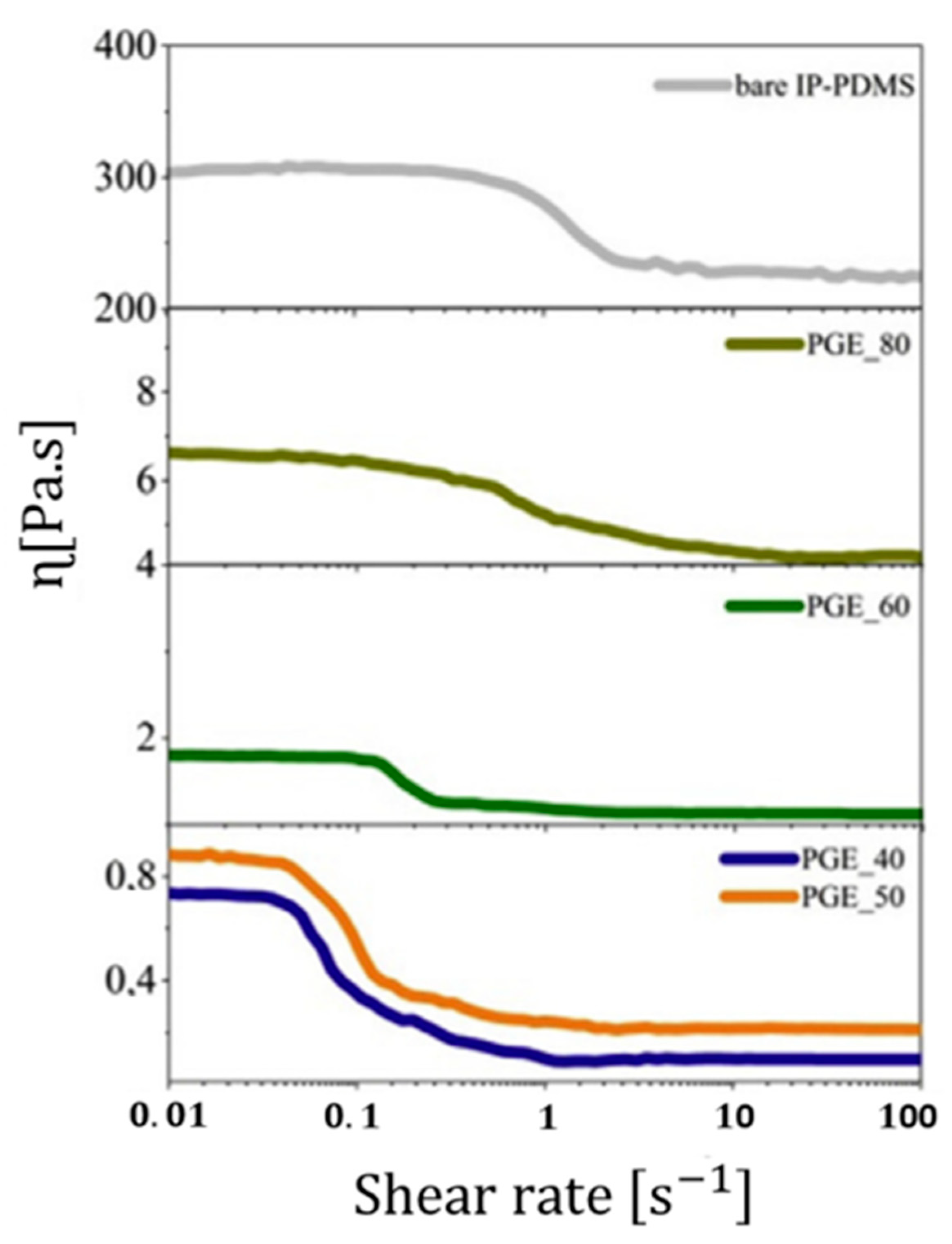
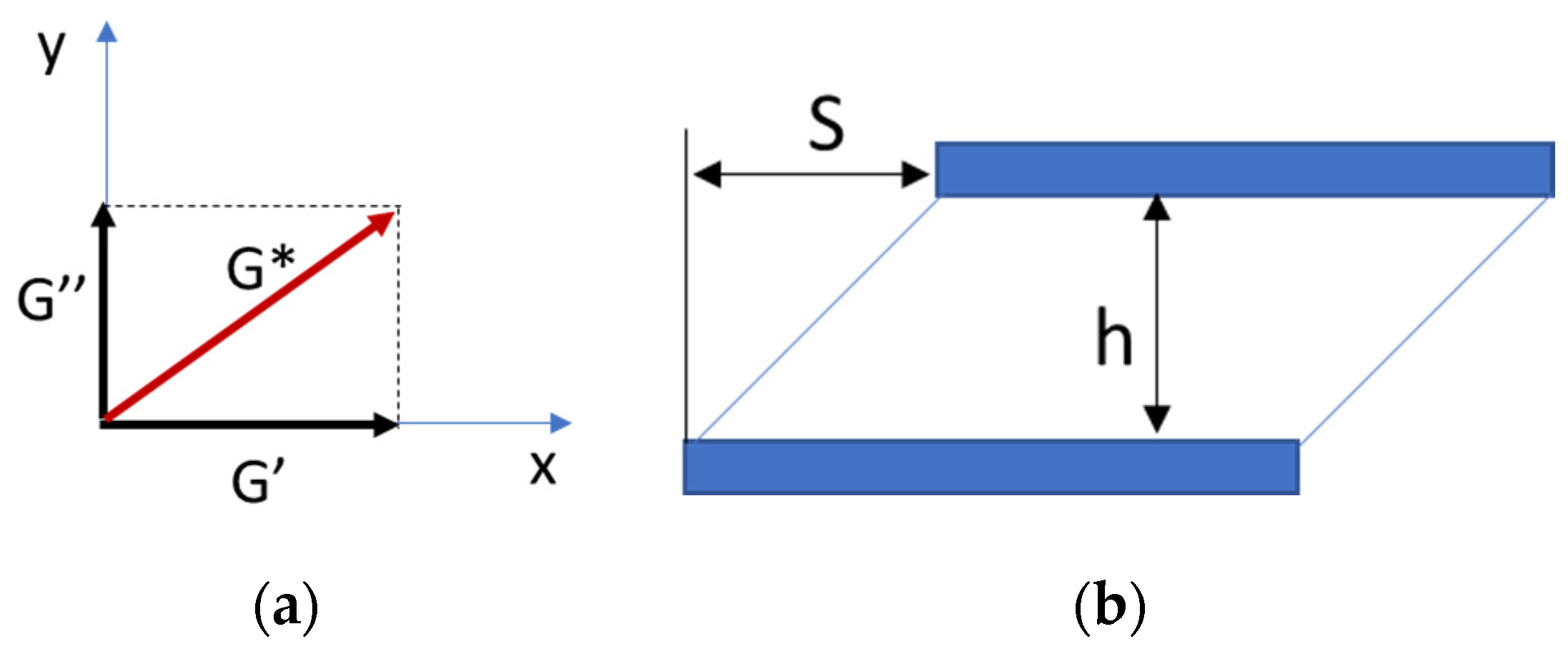
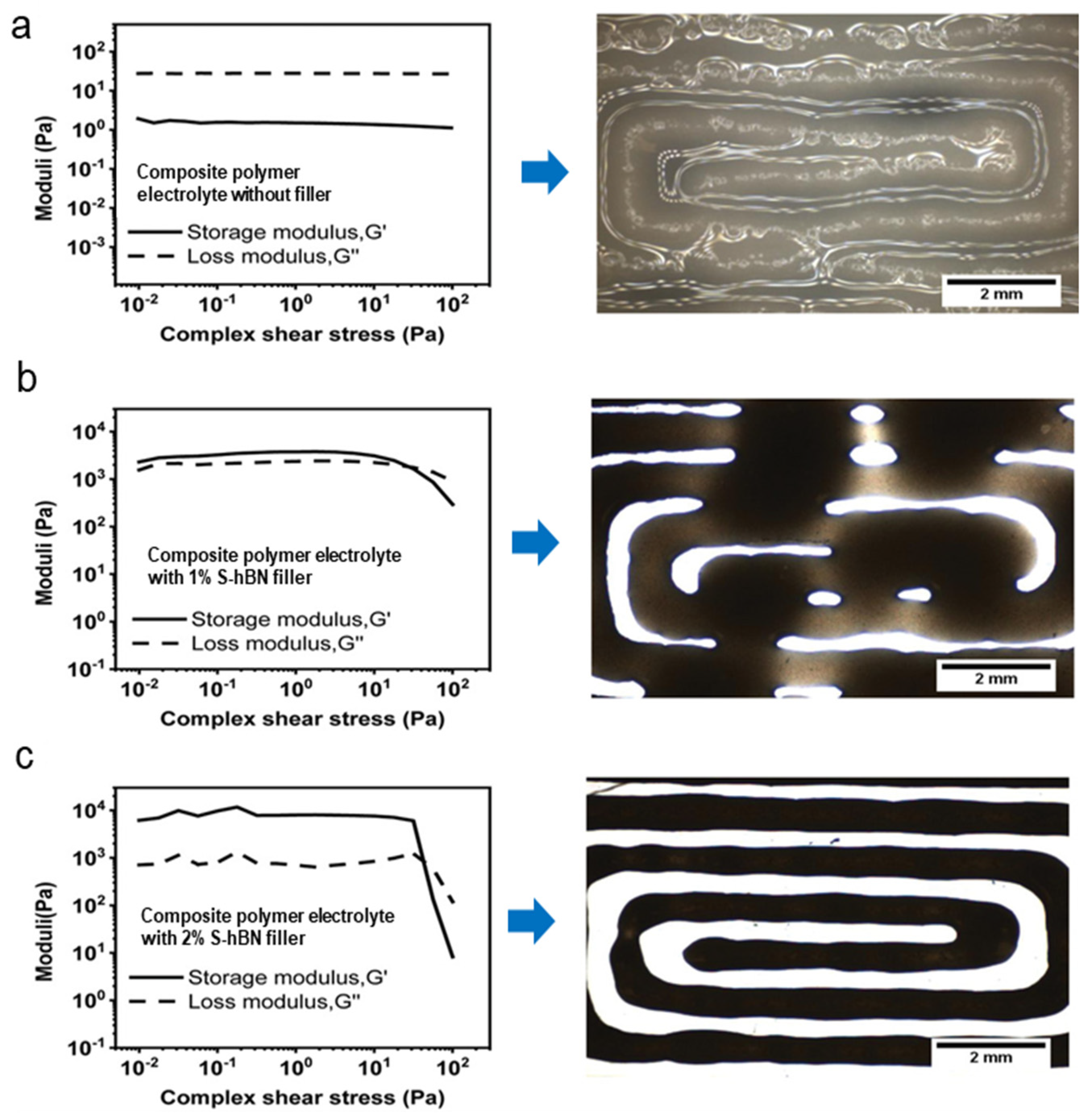
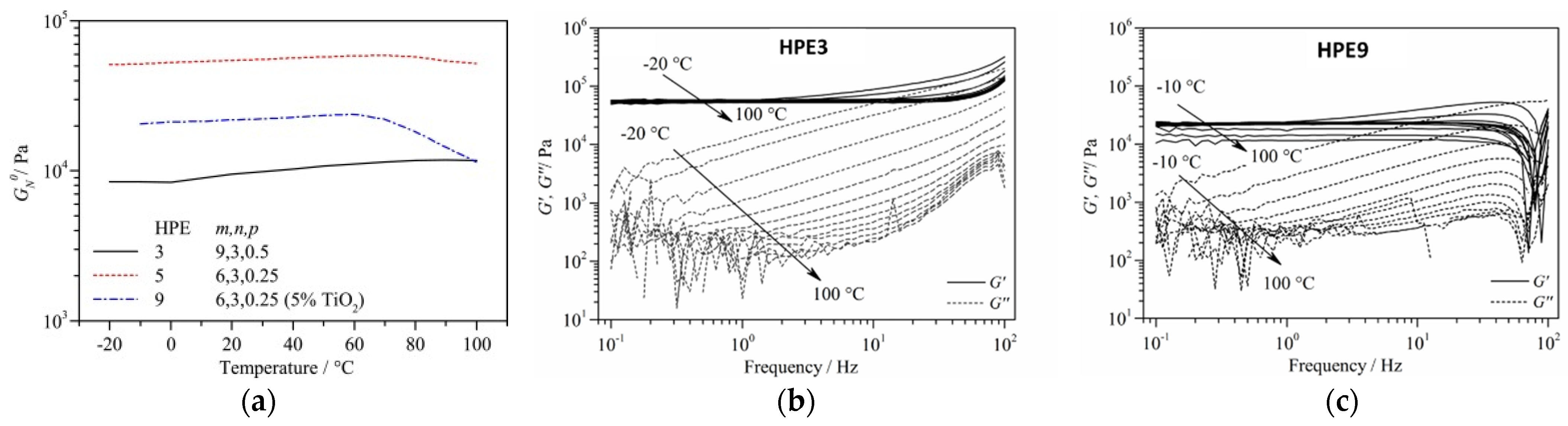
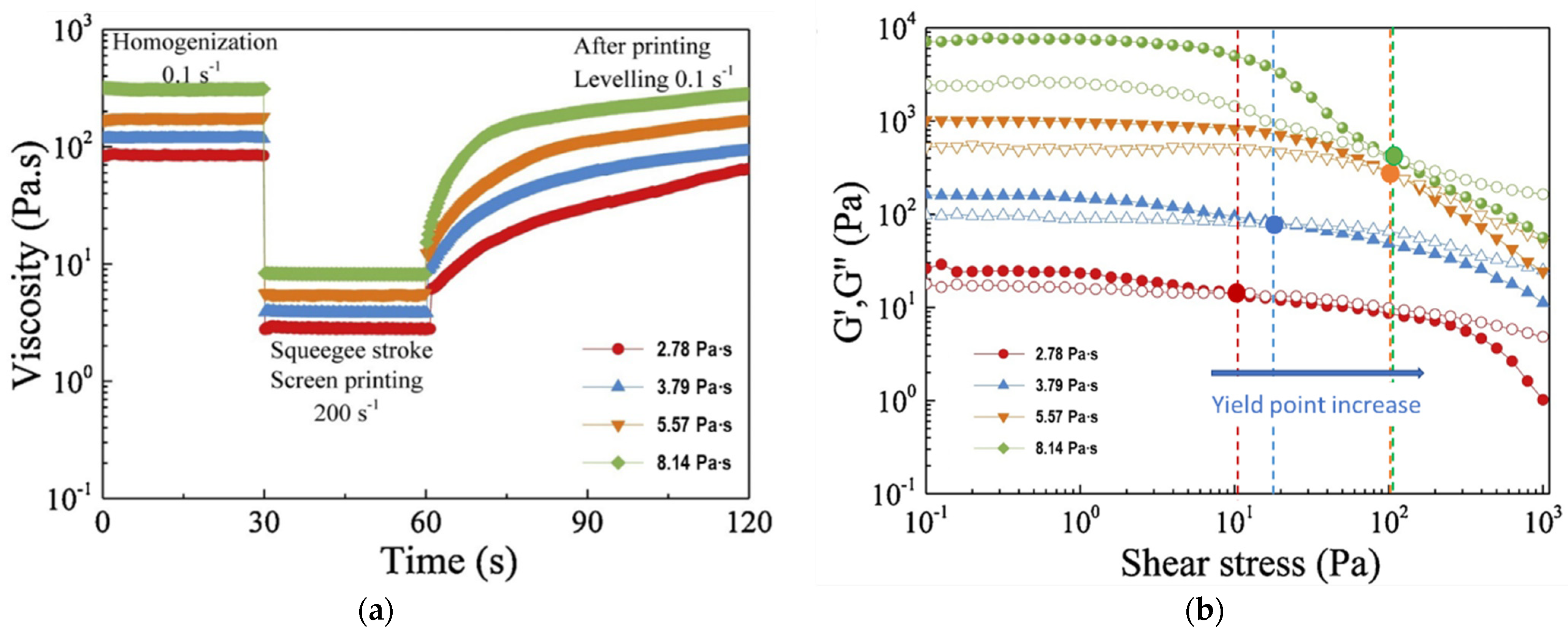
4.3.3. Rheological Properties

As a matter of fact, all the polysiloxane-based electrolytes are characterized by non-Newtonian behavior [32,165] i.e., the viscosity decreases with the increasing shear rate, with a shift in the yield point as a function of composition. Wang et al. [167] have demonstrated that the presence of Newtonian or non-Newtonian behavior is highly dependent on the degree of functionalization of polysiloxane-based liquid electrolytes used in DSSCs. They reported a rather Newtonian behavior up to 90 °C for solvent-free low functionalized polysiloxane electrolytes and temperature-dependent non-Newtonian (shear-thinning) behavior for highly functionalized counterparts.
Polymer gel electrolytes were prepared by Cipolla et al. [32] by dissolving IP-PDMS into an ionic liquid consisting of 0.9 M of DMPII, 0.15 M of I2 in 3-methoxypropionitrile. The yield point (the lowest shear stress above which the electrolyte will behave like a liquid) increased with increasing polymer content (Figure 13). With the increasing polymer amount, the chain-packing density increases with less free volume available for the alignment of polymer chains, thus pushing the flowing point toward higher shear rates.
The polymer amount affects the viscoelastic properties during printing as well as the green properties, such as the strength, density and topological structure after drying. Rheological measurements using either rotational and oscillation tests are used to determine the flow behavior when stress is applied onto the sample or to study the viscoelastic behavior, respectively. The plot between storage modulus (G′) and loss modulus (GG″) versus the shear strain provides the linear viscoelastic region in the amplitude sweep test and gives information about the polymer gel or membrane stability as well as on the elastic properties domination over the viscous properties. The storage G′ and loss G″moduli are the real and imaginary parts of the complex modulus (Figure 14a). The storage modulus G′ represents the elastic portion of the viscoelastic behavior, which partly describes the solid-state behavior of the sample. The loss modulus G″ characterizes the viscous portion of the viscoelastic behavior, which can be attributed to the liquid-state behavior of the sample. Otherwise, the complex shear modulus G* (in Pa) is defined by Equation (5), where ζ is the shear-stress amplitude (ζ = F/A) in Pa and γA is the strain amplitude which is dimensionless or expressed in % (γ = s/h, where s is the liquid plates deflection path and h is the distance between the plates (Figure 14b) [177].
G* = ζ/γ
The shear-thinning effect is less important for screen or blade-coating deposition techniques, for which rather low deposition speeds are used and thick wet layers are deposited. However, the same phenomenon becomes important in spray or inkjet printing processes, as it prevents spraying/printing head clogging, enables obtaining a continuous jet while maintaining a high throughput and controls the printing resolution. The influence of polymer ink rheological properties on the quality of the inkjet-printed pattern is clearly highlighted in Figure 15. For the polymer ink without the S-hBN (sulphonated–hexabornnitride) filler addition, the loss modulus (G″) dominates in the range of shear stress from 0.1 to 100 Pa, revealing a liquidlike behavior, which leads to the collapse of the printed pattern due to the low storage modulus (Figure 15a) [178]. Once the S-hBN filler is added, different viscoelastic properties are observed: the storage modulus (G′) of the inks is higher than the loss modulus (G″) in the region of 10−1 to 10 Pa, indicating a solid-like behavior (Figure 15b,c) with an increase of 3–4 orders of their values. Beyond the yield point (point where the G′ decreases), the viscous characteristic becomes dominant in the high shear stress region. With increasing filler concentration, chain alignment is hampered due to the strong filler–polymer interaction at low shear stress, thus explaining the increase in the static viscosity. However, at high shear stress, this interaction is weaker, allowing the orientation of the polymer chains along the flow.
In conclusion, the polymer inks with S-hBN filler could be extruded smoothly through the nozzle at high shear stress with structure recovery after stress release. The polymer ink containing 2% of filler showed the highest storage modulus (>5 × 10³ Pa) with a high difference between G′ and G″, and, thus, a stiff structure after printing enabling the maintenance of the printed architecture (Figure 15c) as well as satisfying ionic conductivity (0.47 mS cm−1).
Solvent-free polysiloxane-based gel electrolytes were prepared by the sol–gel reaction of PEG-functionalized polymethylsiloxane, followed by dissolution of LiTFSI and radical polymerization of terminal vinyl moieties for Li-based battery applications [130]. The rheological analysis highlights that the size of the methoxy-terminated chains and the addition of an inorganic filler can influence the structural integrity. The density of crosslinking is higher in the electrolyte HP5 containing shorter PEG side chains compared to HP3, leading to a higher plateau storage modulus. This is constant over the studied temperature domain (Figure 16a), proving a solid elastic behavior.
Both the storage (G′) and loss (G″) moduli increase with temperature, with G′ always higher than G″ in the 0.1 to 100 Pa shear stress domain (as expected for a crosslinked polymer), and with no visible flow/melting point up to 100 °C (Figure 16b). However, when TiO2 is added as a filler in the same electrolyte, the polymer electrolyte loses rigidity with the plateau shear modulus decreasing (Figure 16c) and the appearance of an inflexion point at temperatures higher than 60 °C. The electrolyte application domain is slightly limited, as abrupt falls in G′ and G″ are noticed for shear rates above 40 s−1 at RT (Figure 16c), indicating gel structure corruption.
Chen et al. [179] studied the linear viscoelastic properties of polysiloxane electrolytes with phosphonium and oligo(ethylene oxide) side chains containing ionic monomers. They observed that, by increasing the ionic content, the polymer relaxation is delayed (λ = 1/ωc, in s), thus extending the solidlike elastic behavior (G′ > G″), with no flow point limit visible at temperatures around Tg and high deformation frequencies.
Iodopropyl-branched polysiloxane gel electrolytes (Figure 17a) with low temperature thermal crosslinking were reported by De Gregorio et al. [30]. At the initial stage, these electrolytes appear as viscous liquids but after a few minutes curing at 75 °C, an abrupt increase of both moduli is observed with G′ crossing G″ (Figure 17b), which then reaches a plateau marking the end of the crosslinking process. The elastic modulus (G′) reaches a maximum value of around 1.1 kPa after 240 min of curing and the electrolyte ionic conductivity stabilizes at 6.65 × 10⁻² mS cm − 1 (Figure 17c) for lower quaternization rates (GL11_Q55°). The amount of unquaternized iodopropyl influenced both the viscoelastic properties and the ionic conductivity of these systems. The polysiloxane electrolyte gelation time depends on the chain length and crosslinker [180]. Shi et al. [181] showed that the polysiloxane electrolyte flexibility can be improved by increasing the poly(ethylene glycol) diacrylate—PEGDA reticulation precursor chain length owing to Tg decreasing, as highlighted by the blue shift of the loss tangent (tan δ = G′/G″) peak maximum (Figure 18).
Polymer inks’ gelation temperature- and time-dependent behavior significantly affect their printability and shape retention performance, whereas the mechanical strength of the ink is important for the structural stability of the entire DSSC. There are not enough reports on the viscoelastic properties of the polysiloxane-based nor other types of polymer electrolytes used in DSSCs. Thus, much research is needed to optimize the viscoelastic properties of the electrolytes to fit the different spraying or printing techniques and to fulfill the temperature, ionic-conductivity, chemical and electrochemical operating conditions. In this review, we attempt to shed some light on this topic and the desired polymer electrolyte ink properties for a spray or specific printing process are further discussed in Section 5.2.

4.3.4. Electrochemical Stability and Redox Potential

The electrochemical stability of the electrolyte impacts the stability of DSSCs. A number of factors affect the electrochemical stability of redox active ions and molecules in an electrolyte solution. They are connected with (i) the intrinsic electronic properties of both oxidized and reduced forms of a given redox couple, and (ii) their interactions with the environment. The latter are largely determined by the structural changes of the surrounding electrolyte solution accompanying the electron transfer reaction.
All the polysiloxane electrolytes prepared so far for DSSCs rely on the iodine/iodide redox couple as redox mediator. The usable electrochemical window is determined by the potential at which the oxidation/reduction reactions of the electrolyte occur and can be determined by cyclic voltammetry. An example of cyclic voltammetry curve is shown in Figure 19a for the ImIPDMS2-MPII electrolyte, for which oxidation/reduction processes occur outside the −1.0 and 0.8 V vs. Ag/Ag+ (−2.25 and 3.85 V vs. Li/Li+) potential window, thus, a comfortable working potential range [76].
The polysiloxane electrolytes redox potential gives an indication of the expected open-circuit potential and the projected cell performance. The lower the redox potential, the higher the open-circuit potential. In iodine-containing polysiloxane, the redox potential depends on the chemical environment. As such, shifting of the I / I 3 redox potential with the degree of polysiloxane substitution or the type of ionic liquid could be observed (Figure 19b) and related to a more or less facile redox species dissociation [x]. In their study, Assary et al. [182] have shown that various electron-donating and withdrawing substituents influence the oxidation potential of polysiloxanes. Thus, we expect changes to occur as a function of the type and quantity of plasticizing agent or viscosity controlling agent, which are common practices for tuning the printable ink properties.

5. Current DSSC Modules Fabrication and Device Configurations

5.1. Progress in Large Scale DSSCs Modules Development

Transferring from lab scale to an industrial printing process manufacturing is not yet straightforward from the point of view of the types of electrolytes and device configurations tested so far. Although much progress has been achieved for the deposition of the TiO2 photoelectrodes by using printing techniques (Table 3) at high or low processing temperature as a function of the type of substrate, the traditional electrolyte vacuum or injection filling method is still recurrently used for building devices on rigid or flexible substrate. The electrolyte is mainly used in its liquid form [183,184,185,186,187,188,189,190,191,192] or is further solidified through heating [193,194] or UV exposure [195] after filling.
The current processing of larger scale DSSCs has not evolved much yet. The photoanode and counter electrode are each separately deposited on the substrate, usually by screen printing, followed by thermal annealing for particle sintering (Figure 20) in case of glass substrates [196,197]. Obviously for multiple DSSC cells connection in series or parallel, conductive buss bars, usually Ag, are printed followed by protective layer coating to prevent corrosion. After dye sensitization, the photoanode is assembled with the counter electrode via a separator, which also plays the role of sealant (Figure 20), and then the electrolyte is filled in between.
The screen-printing method is by far the most exploited for the photoelectrode and counter electrode deposition, but not for the electrolyte; even if based on the reported rheological properties, the gel-like electrolytes should be compatible with such deposition methods. Roll-to-roll processing has so far been tested only for solid state DSSCs [198], where the redox mediator is replaced by a hole collector. From the commercial point of view, options exist on the market as thoroughly summarized by Aslan et al. [197] with companies like GCell, NREL, Konarka, Dyenamo or 3G Solar already offering solutions for portable electronic devices, Internet of Things and sensors. However, it is hard to gather information on the current state of development in electrolyte formulations and deposition technologies.

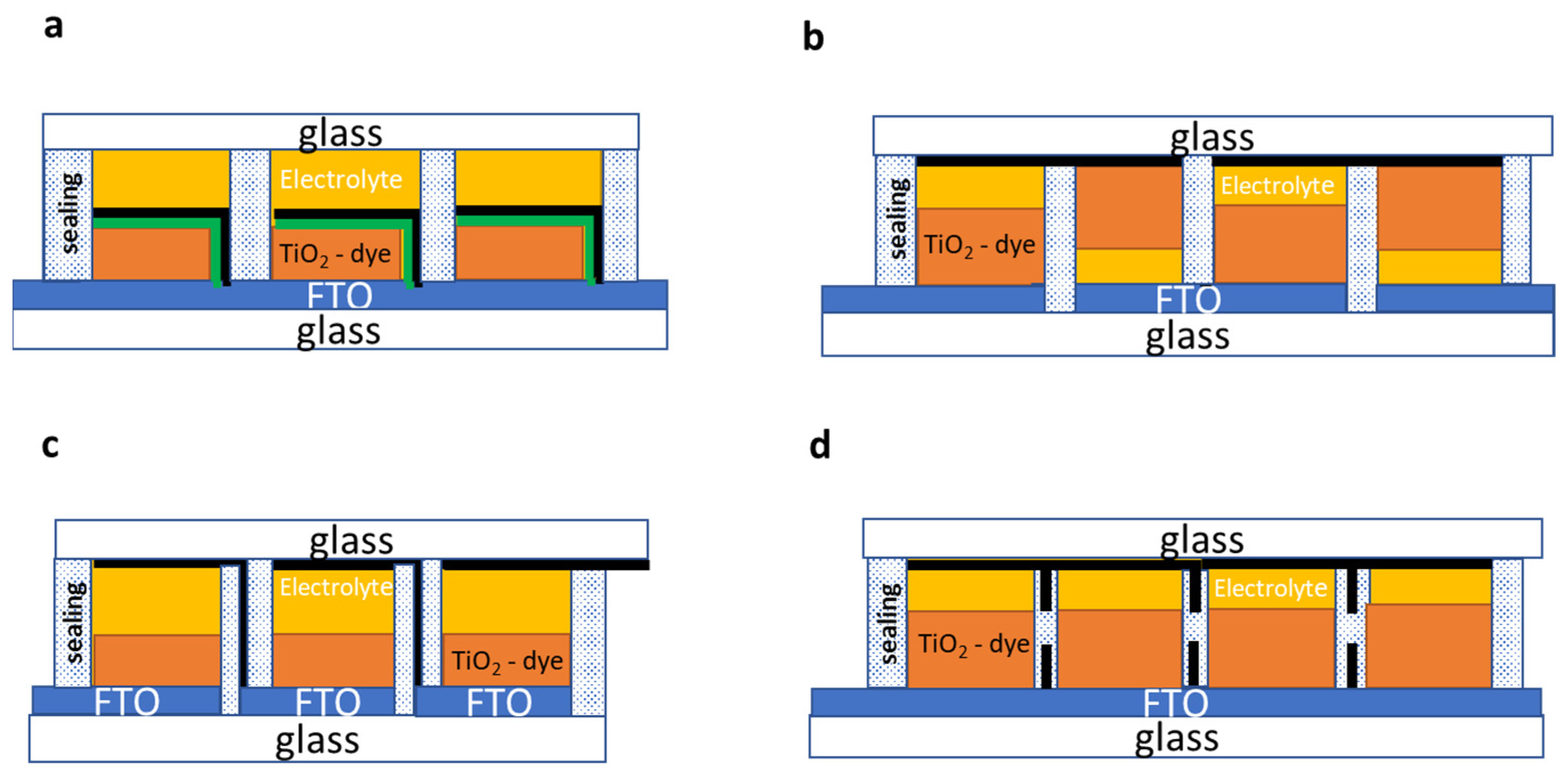
5.2. DSSC Module Configuration

Different DSSC module connections were reported (refer to Table 3), including series or parallel configurations, for maximizing the voltage or the current output, respectively. Three types of configurations are generally exploited for the series connection: the monolithic (Figure 21a), the W-series (Figure 21b), the Z-series (Figure 21c) and parallel connection (Figure 21d).
The monolithic configuration (Figure 21a) is economically more interesting as only one conductive substrate is used and the fabrication process is much simplified since components are stacked one by one on the substrate. However, cell operation relies on proper electrolyte infiltration in the dye-sensitized TiO2 and the porous barrier layer. For this reason, the operation of this type of device relies on uniform liquid electrolyte injection filling [183,184]. Therefore, any of the polysiloxane-based electrolytes with lower viscosity (<10,000 cPs) can be used in such devices, since effective pore filling in standard [162] or porosity-tuned [199] TiO2 electrodes has already been proven. Most of the time, the electrolyte remains in its liquid form; however, the use of thermosetting PEO/PVDF-based electrolytes, which are liquid when injected and become solid after thermal treatment, was also reported [193] in large surface modules. Encouraging results were also obtained on lab-scale devices containing such thermosetting electrolytes based on polysiloxane polymers [27,30,32]. The advantage of this configuration is that no special care must be given to electrolyte volume contraction since device sealing from UV and ambient factors is realized after polymerization. However, special attention must be given to the sealing-processing temperature which should be lower than the dye-degradation temperatures (<100 °C).
For the W-series connection, a higher active surface can be attained as no conductive interconnections have to be printed in between the two opposite electrodes lines [191]. However, cell separation is required, as illustrated in Figure 21b. The difficulty of this design lies in matching the performance of each cell as front and back illumination are alternating, with reversed-side illuminated cells having a lower short-circuit current due to light absorption by the electrolyte and the counter electrode. In terms of electrolyte printing, the W-series configuration needs more precision in masking and in controlling the printed layer thickness since the electrolyte has to be correspondingly deposited on each side, on top of the TiO2 electrode, and ensures a proper interface contact with both the C/Pt and FTO-coated substrates. This would also imply matching TiO2 layer printing quality on the two substrates. This is why viscoelastic thermosetting electrolytes, which are injected after heating (60 °C < Tflow < 100 °C) and which solidify after cooling, are more easily manipulated for building such device configurations. The gelation point should lie somewhere between −10 and 50 °C, which corresponds to the DSSC operational range [200], especially for vertically mounted large-scale DSSCs where failure owing to gravity-entrained electrolyte flow or phase separation represents a high risk. Photo crosslinking can also be envisaged [201,202] as long as both sides of the device are irradiated.
The Z-series configuration consists of similar electrode configurations interconnected through conductive buss bars, as shown in Figure 21c. Each cell is also isolated to prevent buss-bar corrosion by the redox electrolyte [186,190,192]. The advantage of the Z-contact module is the high voltage output, while the disadvantages are the small active area due to the three layers (sealing/conductive/sealing) needed between the cells and the low fill factor deriving from the conductive layer series resistance. As for the W-series connection, matching the cells thickness is important; thus, good control over the electrolyte layer printing thickness must be ensured. For this module design specifically, since thick conductive buss bars (30–50 µm) must be deposited in between each cell, the electrolyte film volume variations must be minimized. Consequently, solvent-poor or solvent-free polymer electrolytes with thermosetting or thermoplastic properties should be used. As opposed to the W configuration, the Z-series structure should be simpler to fabricate by using current in-line printing processes since the electrolyte is printed on the same electrode (TiO2 photoelectrode). For this configuration, ensuring counter electrode layer flexibility and minimizing the TiO2 and electrolyte layer thickness is very important when aiming for stable devices.
Finally, for parallel connected modules, the voltage output is maximized. The cells are connected topwise and bottomwise (Figure 21d) through the counter electrode and the conductive substrate, respectively [187,188,194]. In addition, electron collectors are deposited in the form of grids surrounding the individual cells to maximize the charge collection and by pass the conductive layer series resistance.
For parallel connected modules, as for those in a series, viscous (polysiloxane) electrolytes with thermosetting or thermoplastic properties should be targeted for effective photoelectrode penetration and for facile device lamination. Photopolymerization would only be possible through the transparent counter electrode, provided that the used sensitizer is UV-stable.

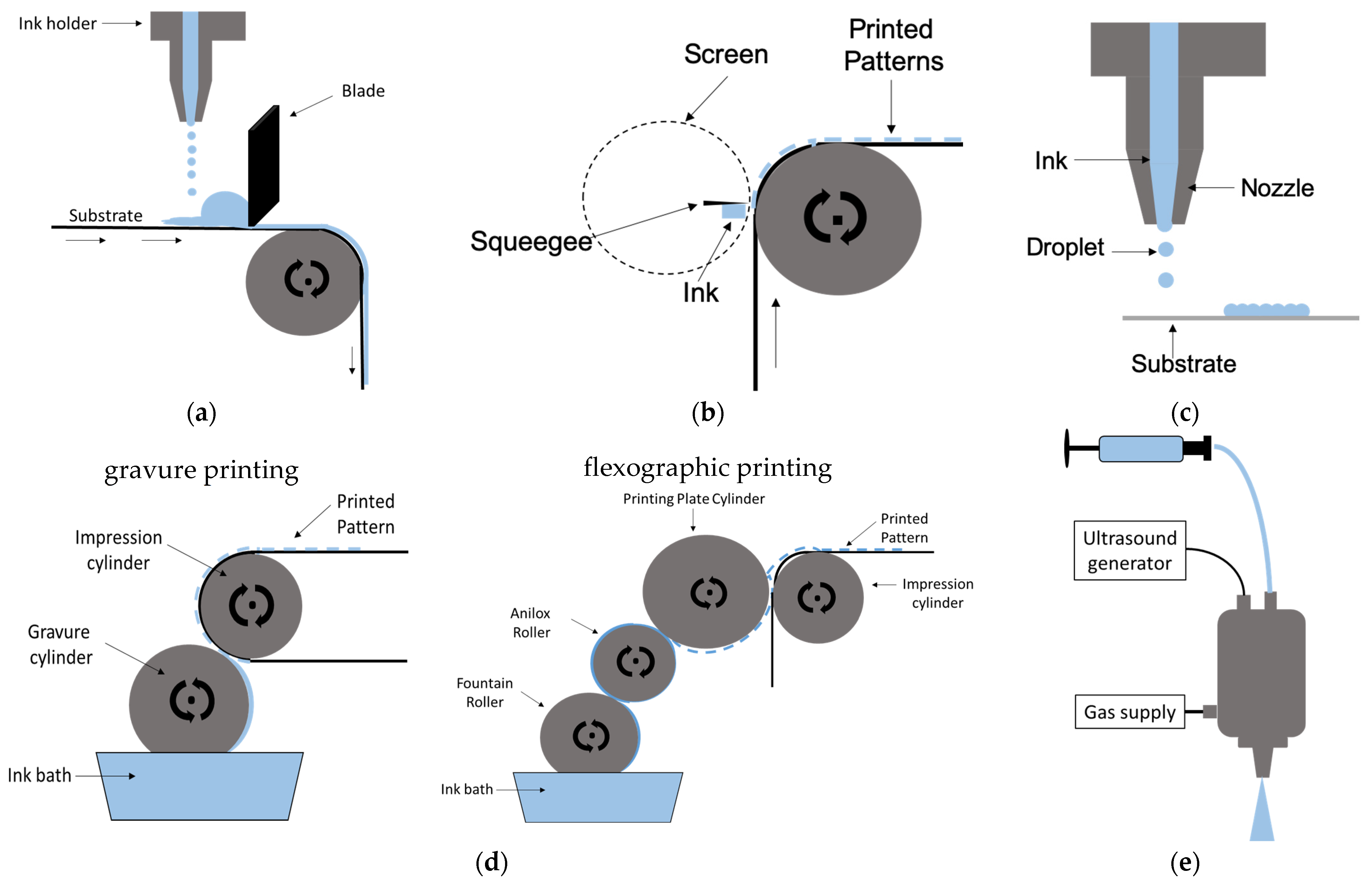
5.3. Polysiloxane Viable Printing Technologies

As detailed earlier, polysiloxane electrolytes are ideal candidates for the development of printing processes owing to their favorable thermal, chemical and electrochemical stability but also due to their high versatility in solubilizing ionic liquids and compatibility with other polymers and organic solvents. The methods used for controlling the polysiloxane viscosity were already described in Section 4.3. As follows, the printability of the polymer electrolytes, including those that are polysiloxane-based, is further evaluated with regard to the different printing technologies and device designs. The rheological properties of the electrolyte inks and the mechanical properties of the resulting films in view of the different printing technologies are further discussed.
A simplified representation of scalable electrolyte layer deposition technologies is presented in Figure 22, whereas Table 4 gathers the operation limits characteristic of each printing technology, including the electrolyte ink rheology, printing throughput and printed layer thickness and resolution. Based on the viscosity values reported in Table 2 and rheological properties presented in Section 4.3.3, spraying and inkjet printing of polysiloxane-based electrolytes are very challenging in terms of viscosity and surface tension adjustment. Blade, slot or screen printing are better suited and more easily transposed to continuous online roll-to-roll processes, as detailed further.

5.3.1. Blade Coating

Blade coating is a very versatile deposition technique, compatible from medium viscous to thick pastes, with viscosities ranging from 1000 to 50,000 cPs [203] (Table 4).
The blade-coating technique involves spreading the material with the help of a sharp blade that is never in direct contact with the substrate (Figure 22a). Substrate heating is often used to encourage film reticulation especially when consecutive layers have to be deposited. The wet layer thickness is determined by the blade distance to the substrate, the coating speed and the paste viscosity [41]. Typically, thick wet layers (10 to 150 µm) are deposited with a modest layer uniformity (±1 µm.) (Table 4). Substrate patterning can be realized by using a mask with a predefined pattern and thickness as illustrated in Figure 22a or by pumping the ink through patterned coating heads (also called slot-dye coating). For a traditional blade-coating process, the presence of a shear-thinning effect is not wanted as it will destabilize the coating by increasing the minimum wet layer thickness [204]. Neither is the surface wetting, as large quantities of polymer electrolyte are poured on the substrate. Liquid wetting can be easily fixed by corona or plasma treatment while decreasing the coating gap allows depositing thinner films and working at higher coating speeds [205].
The shear stress ( γ ˙ in s−1) for blade and slot-dye coating can be calculated according to Equations (6) and (7) [206], where υ is the coating speed (cms−1), h is the slot height (cm), Q is the solution flow (cm3 s−1) and b is the slot width (cm).
γ ˙ = υ h
γ ˙ a p p = 6 · Q b   h 2
The shear stress typically lies in the range of 103–104 s−1. The thickness t of the deposited layer is given by Equation (8) [207]:
t = ɸ υ · w · s %
where ɸ is the flow rate of the paste coming out from the leak, υ is the speed of the system, w is the width of the coated surface and s% is the solid content.
For blade-coating processing of viscous polysiloxane inks, viscosity stabilization should be checked for shear rates superior to 50 s−1 [208,209] and a viscoelastic behavior (elastic modulus exceeding the loss modulus) confirmed in the processing frequency domain, with a storage modulus exceeding 10 Pa for structural stability. Whenever the ink is supplied through a coating head as in slot-dye coating, the liquid surface tension should be kept between 25 and 50 mN/m [210]. For uniform wet film application, proper leveling and smooth crack-free layer development, the polymer ink should present a thixotropic behavior with a medium recovery time (solid-like behavior recovery after the blading shear stress is removed) (Figure 23). A too fast recovery rate for such thick wet layers, as those obtained by blade coating, might cause ribbing effects (Figure 24), whereas fast solvent evaporation can lead to film cracking. Ideally, the recovery time should be in the range of few minutes [211].
For both blade and slot-dye coating, high-boiling solvents should be chosen to avoid film cracking and layer thickness inhomogeneity due to fast solvent evaporation, as well as to avoid injection-slot clogging.
Composition tuning for attaining electrolyte film flexibility for plastic devices, but also film cohesion and crack-free property, are key aspects for cell durability. For increasing film flexibility, apart from the reticulating agents (PEO, PVA, PMMA, PAN, etc.), plasticizing agents such as PVB, PVDF, PVA or PEG have to be added [186,194,210] in combination with high-boiling solvents. PVB-based and PVDF-based electrolytes have higher stability and processability, while PEO-based electrolytes provide the best ionic conductivity and width of the electrochemical window. PVDF-based electrolytes can also offer high ironic conductivity and a wide electrochemical window, as long as an effective electrode’s pore filling is ensured [212,213,214].

5.3.2. Screen Printing

Screen printing allows better precision in the obtained layer thickness (±100 nm). Materials deposition geometry is defined by a flexible mesh, or mask, having the desired pattern through which the precursor paste is squeezed by a squeegee (Figure 22b). The wet layer thickness can reach 500 µm, but lies typically below 100 µm, and is determined by the mesh and screen geometry that defines the printed volume, the paste dry content and rheology [215]. In rotary screen printing, the mesh is mounted on a roller and a squeegee forces the ink through the mesh and onto the substrate.
If the printed polymer is to be deposited with high dimensional specificity, it must wet the substrate, have a minimum viscosity of 500 cPs [216] and a fast recovery rate in order to maintain its structural stability after deposition. As for the blade-coating technology, the liquid surface tension is not so critical because the substrate surface tension can be easily tuned by plasma [217] or corona [218] treatment. In general, the inks surface tension must be 10 mN/m lower than that of the substrate [209,219].
Various large-area DSSC modules and panels based on screen-printing fabrication processes have been reported (Table 3) for which the electrolyte was filled through a hole. Developing a fully screen-printed DSSC depends on developing a suitable polymer electrolyte.
Electrolytes with a jelly structure are not suitable for screen printing because their structure will be destroyed and they become liquid at very low shear-thinning rates. Thermally or UV-curable polymer electrolytes with tuned viscoelastic properties adapted to the processing deposition rates should be designed.
Fully continuous processing is best achieved through rotary screen printing, which uses the same principle as blade coating, although in this case, the web of the screen is folded onto a tube and the squeegee and the ink are placed inside the tube. As the screen rotates with the same speed as the substrate, the ink is continuously pushed through the open area of the screen by the stationary squeegee, making a full print upon every rotation. Much higher processing speeds can be achieved by use of rotary screen printing (>50 m/min). With the screen-printing process, a printing resolution of 50 lines/cm can be reached [220].
The deformation rates in screen printing are in the order of 103 s−1, whereas the squeegee lift-off after pattern deposition is in the order of millisecond [221], meaning that the polymer ink should be able to rapidly transit (within few dozens of seconds) from liquid-like to solid-like behavior (i.e., have a fast recovery rate) when passing from high (injection equivalent) shear-stress to static conditions. The recovery time is highly dependent on the ink viscosity, as illustrated in Figure 24a, and should be in the range of few seconds [222]. The yield point (transition from viscous to liquid-like behavior) should be achieved for screen-printing corresponding shear rates (shear stress > 50 s−1), with the storage modulus dominating over the loss modulus above the yield point (as for the ink with 5.57 Pa·s viscosity, orange traces in Figure 24b), with values exceeding 10 Pa for achieving pattern structural stability.
Figure 24. Illustration of recovery rate (a) and storage and loss moduli crossing (yield) point variation (b) as a function of ink viscosity for screen-printing equivalent shear stress values. Adapted with permission from [221]. Copyright 2023, Springer.
Coatings 13 01164 g024

5.3.3. Flexographic and Gravure Printing

In flexographic printing, the transfer of ink happens through direct contact of a soft printing plate cylinder onto which the desired motif stands out as a relief. The ink is transferred to the printing plate via a ceramic anilox roller with engraved microcavities embedded into the exterior surface. The anilox cylinder is continuously supplied with ink by contact with a fountain roller that is partly immersed in an ink bath. The excess ink is removed by a blade ensuring good control of the wet layer thickness [223].
In gravure printing, an image is created by engraving a negative of the image being printed onto a gravure cylinder, which is then coated with ink and the image is transferred to the substrate using pressure.
These methods allow printing layers of 1 to 50 µm thick [224] with a resolution of 70 to 130 lines/cm, with superior resolutions for gravure printing [225]. The thicknesses of the deposited layers depend on the speed of the press, the transfer characteristics of the product, its viscosity (10–500 cPs) and the surface condition of the support.
In these inks, the solvents are temporary components since they are eliminated by evaporation and/or infiltration during the drying of the ink. They do not theoretically contribute to the properties of the printed ink film. For polymer printing, the solvents used in gravure should have a high-boiling point (toluene, glycol ethers, esters, 3-methoxypropionitrile—MPN or N-methylpyrrolidone—NMP). Similar rheological properties as for screen-printed inks should be targeted, with the difference that for this process, the polymer ink viscosity should be lower.

5.3.4. Inkjet Printing

The inkjet printing technique involves release of small ink drops through a printhead, controlled by the inkjet printer itself. This printhead contains a series of nozzles, which allow the ink drops to be released on to the substrate (see Figure 22e). To produce and control the droplets, two main methods are used, either continuous ink jet (CIJ) or drop-on-demand (DOD). In the case of CIJ, each drop is electrostatically charged and then accelerated by an electric field toward the substrate that slides along a plane, while the drop generator ejects the ink drops. The DOD involves hardware/software techniques for drop formation: the ejection occurs only when needed according to the pattern to be printed. The DOD method is more suitable for patterns that are more complex since its accuracy is much higher.
Ink stability at rest determines the shelf-life, whereas the rheological properties decide the printing throughput and ink spreading on the substrate. Usually, the viscosity required for inkjet printing is rather low (<20 cP) [226] and particle sizes should not exceed 200–500 nm to avoid printing-head clogging [227]. The ink surface tension should not exceed 30 mN/m (Table 4).
The representative characteristic dimensionless numbers that affect the behavior of the ink are the Reynolds number (Re), Weber number (We) and Ohnesorge number (Oh) [133,134,228].
R e = υ ρ α ɳ
W e = υ 2 ρ α γ
O h = W e R e = ɳ ( γ ρ α )
In these equations, υ , α, ρ , ɳ and γ represent the velocity, characteristic length (typically drop diameter), density, dynamic viscosity and surface tension of the polymer ink, respectively. Re and We refer to the ratio of the inertial force to the viscous force, and the balance between the inertial force and the surface tension, respectively, while Oh relates the viscous force to the inertial force and surface tension. The Z parameter (Z = 1/Oh) is a key property for the inkjet process since it is directly connected to the rheological properties of the polymer ink, such as dynamic viscosity ( ɳ ), density ( ρ ), surface tension (γ) and the characteristic length (a), which is the diameter of the nozzle. Therefore, the Z parameter of the electrolyte-based inks has to be optimized within the printability region determined by Reis (1 < Z < 10) [212]. At low Z values, viscous dissipation prevents drop ejection, whereas at high Z values, the primary drop is accompanied by a large number of satellite drops.
The minimum pressure required to start a flow for the ink with a yield stress can be described by p m i n = 4 L D ζ [229,230] where pmin is the minimum pressure required, L is the nozzle length, D is the nozzle diameter, and ζ is the yield stress of inks. The shear stress during inkjet printing can be calculated by using Equation (12), where Q is the polymer ink-flow rate (mL/s) and R is the nozzle radius (mm).
γ ˙ a p p = 4 · Q π R 3
The strong shear-thinning and fast recovery behavior (faster than for screen printing) are highly desirable in injection-based printing processes as shear-thinning behavior enables the easy extrusion of inks through a narrow opening and the rapid-recovery behavior allows the inks to quickly achieve enough mechanical strength after printing to resist deformation. During viscous polymer injection, a low yield stress is highly desirable as the injection is not continuous but starts and stops frequently during printing. Yield stresses of inks is determined as the crossover point where G′ equals to G′′, as previously illustrated in Figure 13. The shear rate for spraying or the inkjet process is very high (104–105 s−1).
Generally, the clogging issue appears if an overlarge filler is used, solvent evaporates too fast and/or the ink is poorly dispersed. To avoid these issues, the size of filler particles, if present, should be less than 1/10th of the diameter of the printing head aperture [231], high-boiling solvents should be used and polymer ink surface tension and viscosity should be adjusted, respectively.

5.3.5. Spray Coating

The spray process is divided in three main steps: (a) transport of the precursor solution toward the spraying nozzle; (b) atomization of the precursor solution that generates the aerosol; and (c) precursor spreading and wet film formation on the substrate, as illustrated in Figure 22e. During aerosol transport, the fine liquid droplets flow rate ( F a ) is described by Equation (13), where P is the vapor pressure, η the viscosity, σ the surface tension and K a coefficient depending on the power used to generate the mist [232].
F a = K P σ ɳ
The viscosity limit drops significantly for this process. Ideally, they should not exceed 150 cPs [233]. Of course, more viscous polymer inks can be sprayed if the proper nozzle aperture is chosen, knowing that the spray-coating resolution decreases with the aperture size.
Viscoelasticity, shear viscosity and surface tension have been reported as key properties affecting the spray performance with direct impact on the droplet size distribution generated by either ultrasonic, two-fluid or pressure nozzles [234,235,236].
During mixing and pumping, the polymer ink (which might contain inorganic filler particles) is exposed to shear rates between 1 and 100 s−1 or even higher, whereas during airless spraying, shear-rates up to 105–106 s−1 are reached [237]. Wet layer levelling is very important during spraying, as it determines the layer homogeneity and occurs for shear rates between 10−2 and 1 s−1, as for blade-coating methods. The shear stress for spray coating can be calculated according to Equation (12) [206], where Q is the solution flow.
The spraying of polymer electrolytes is carried out at room temperature with previous solution heating (often reported for injecting thermosetting or thermoplastic polymer electrolytes) for more facile injection. Solvent evaporation and film drying steps are required to achieve layer crosslinking. Sometimes the substrates are slightly heated to achieve film stabilization. As for slot-dye coating, medium recovery rates should be used to allow proper liquid film leveling.

6. Summary and Prospects

Generally speaking, since the energy demand has increased significantly in the last 30 years, we are always in search of environmentally friendly, alternative sources of energy, whether for high-, medium- or low-energy consumers, as any effort in this direction can lower the worldwide energy production impact. In this sense, dye-sensitized solar cells (DSSCs) are an ideal alternative energy source exploiting both solar and artificial light with a great potential for contributing to static or remote applications such as the Internet of Things (IoT) or portable electronics.
Although the DSSC processing technology is quite mature for small- and medium-scale devices based on liquid electrolytes, with efficiencies reaching competitive values as those reported by traditional Si solar panels (15.2% reported in 2023), its mass production is limited by the short-term stability induced by the electrolyte liquid usage itself. Likewise, current device component fabrication and encapsulation cannot be adapted to an online fabrication process. This also explains the rather slow progress in DSSC efficiency. Indeed, the highest reported performances still refer to liquid or quasi-solid electrolyte-based electrolytes with most advances mainly concerning the development of new (co)sensitization methods enabling visible and near-infrared light harvesting; new electrolyte compositions comprising jellifying agents, fillers or polymers that reduce the risk of leakage; and the development of new redox couples with lower redox potential for increasing the open-circuit potential or the development of solvent or iodine-free electrolytes for improved device stability.
Nevertheless, in the majority of cases, the device encapsulation is based on joining the chemically deposited dye-sensitized photoanode with the physically deposited counter electrode via a separator, which also serves as sealant and adhesive, followed by electrolyte filling in between. Even more, except the all-solid monolithic and junction DSSC device designs, which lead to modest performances due to the lower photoanode specific surface, poor electrolyte penetration and extended charge diffusion path, all the other device structures proposed were mostly tested with liquidlike electrolytes. Consequently, the development of judiciously tailored printable electrolytes to fit the different device configurations is highly important for the rapid mass production and commercialization of efficient and stable next-generation DSSCs. Thus, in the following years, we expect to witness intensive and rapid development in the field of printable electrolytes capable of meeting the current online roll-to-roll-like modules processing demand, with Z-series and parallel configurations having the highest potential for high scale exploitation.
Related to this, we particularly highlight in this review the amazing properties and versatility (compatible with high boiling-point solvents and ionic liquids) of polysiloxane-based electrolytes. Indeed, their high thermal and electrochemical stability, low toxicity, high ionic conductivity and their potential to act both as electrolyte and redox mediators render them very attractive for the future development of printable electrolytes. Furthermore, high consideration is given to the printability of the polysiloxane-based electrolytes with respect to roll-to-roll-like printing technologies and online device encapsulation. As highlighted in the review, the polymer electrolyte, and in particular the polysiloxanes rheological properties, can easily be tuned to fit almost all printing technologies by adding ionic liquids and by tuning the type of side chain or the degree of functionalization. Adding polymers and fillers is an imaginable strategy for tuning ionic conductivity and mechanical properties, as well as the polymer reticulation mechanism, which has barely been explored, even for common electrolyte compositions.
In terms of scalable deposition methods, the inkjet printing and spraying methods impose the highest restrictions in terms of viscosity and are less suited for any polymer electrolyte processing but are already explored for electrode dye sensitization and photoanode deposition. Screen printing, blade or slot-dye coating or any combination of these are the most promising electrolyte deposition processes for achieving precise substrates patterning and a fine layer thickness control.
Once an online fabrication process is developed, the potential for exploiting this technology for low-power consumers is endless, including displays, smart sensors, IoT, portable electronics and smart windows.

Supplementary Materials

The following supporting information can be downloaded at: https://www.mdpi.com/article/10.3390/coatings13071164/s1, Table S1: Performance of thermosetting and thermoplastic electrolytes in DSSCs; Table S2: Photovoltaic performances of DSSCs using liquid and (quasi-) solid electrolytes based on ionic liquids under AM 1.5 simulated solar light irradiation; Table S3: Best photovoltaic performances for the iodide containing PILs-based DSSCs reported in literature.

Author Contributions

L.M. manuscript conceptualization, drafting and revision, A.K.B. manuscript drafting and revision, N.D. figure conceptualization and manuscript drafting, J.D. bibliography synthesis into Tables, P.C. manuscript editing and revision as well as funding acquisition, F.B. and R.C. manuscript revision and funding acquisition. All authors have read and agreed to the published version of the manuscript.

Funding

This research was funded by Agence Nationale de la Recherche grant number 17-CE05-0020 and IDS FunMAT (International Doctorate School in Functional Materials) grant number 2010-0004/0001.

Institutional Review Board Statement

Not applicable.

Informed Consent Statement

Not applicable.

Data Availability Statement

Literature data analyzed in this study were a re-analysis of existing data, which are openly available at locations cited in the reference section.

Conflicts of Interest

The authors declare no conflict of interest.

References

  1. Available online: https://www.spglobal.com/commodityinsights/en/market-insights/latest-news/oil/100621-global-energy-demand-to-grow-47-by-2050-with-oil-still-top-source-us-eia (accessed on 3 March 2023).
  2. Available online: http://www.greenpeace.org/international/en/publications/Campaign-reports/ClimateReports/Energy-Revolution-2015/ (accessed on 3 March 2023).
  3. Green, M.A.; Emery, K.; Hishikawa, Y.; Warta, W.; Dunlop, E.D. Solar Cell Efficiency Tables (Version 48). Prog. Photovolt. Res. Appl. 2016, 24, 905–913. [Google Scholar] [CrossRef] [Green Version]
  4. Zhao, J.; Wang, A.; Green, M.A.; Ferrazza, F. 19.8% Efficient “Honeycomb” Textured Multicrystalline and 24.4% Monocrystalline Silicon Solar Cells. Appl. Phys. Lett. 1998, 73, 1991–1993. [Google Scholar] [CrossRef]
  5. Zhang, Z.; Xi, F.; Ma, Q.; Wan, X.; Li, S.; Ma, W.; Chen, X.; Chen, Z.; Deng, R.; Ji, J.; et al. A Nanosilver-Actuated High-Performance Porous Silicon Anode from Recycling of Silicon Waste. Mater. Today Nano 2022, 17, 100162. [Google Scholar] [CrossRef]
  6. Eshraghi, N.; Mahmoud, A.; Cloots, R.; Boschini, F. Silicon-Carbon Composite Anode Material. WO2,020,099,589A1, 22 May 2022. [Google Scholar]
  7. Chopra, K.L.; Paulson, P.D.; Dutta, V. Thin-Film Solar Cells: An Overview. Prog. Photovolt. Res. Appl. 2004, 12, 69–92. [Google Scholar] [CrossRef]
  8. Bloss, W.H.; Pfisterer, F.; Schubert, M.; Walter, T. Thin-Film Solar Cells. Prog. Photovolt. Res. Appl. 1995, 3, 3–24. [Google Scholar] [CrossRef]
  9. Mirabi, E.; Abarghuie, F.A.; Arazi, R. Integration of Buildings with Third-Generation Photovoltaic Solar Cells: A Review. Clean Energy 2021, 5, 505–526. [Google Scholar] [CrossRef]
  10. Ehrler, B.; Alarcón-Lladó, E.; Tabernig, S.W.; Veeken, T.; Garnett, E.C.; Polman, A. Photovoltaics Reaching for the Shockley–Queisser Limit. ACS Energy Lett. 2020, 5, 3029–3033. [Google Scholar] [CrossRef]
  11. Berhe, T.A.; Su, W.-N.; Chen, C.-H.; Pan, C.-J.; Cheng, J.-H.; Chen, H.-M.; Tsai, M.-C.; Chen, L.-Y.; Dubale, A.A.; Hwang, B.-J. Organometal Halide Perovskite Solar Cells: Degradation and Stability. Energy Environ. Sci. 2016, 9, 323–356. [Google Scholar] [CrossRef]
  12. Ragoussi, M.-E.; Torres, T. New Generation Solar Cells: Concepts, Trends and Perspectives. Chem. Commun. 2015, 51, 3957–3972. [Google Scholar] [CrossRef] [Green Version]
  13. O’Regan, B.; Grätzel, M. A Low-Cost, High-Efficiency Solar Cell Based on Dye-Sensitized Colloidal TiO2 Films. Nature 1991, 353, 737–740. [Google Scholar] [CrossRef]
  14. Kalyanasundaram, K. Dye-Sensitized Solar Cells; EPFL Press: Lausanne, France, 2010. [Google Scholar]
  15. Kokkonen, M.; Talebi, P.; Zhou, J.; Asgari, S.; Soomro, S.A.; Elsehrawy, F.; Halme, J.; Ahmad, S.; Hagfeldt, A.; Hashmi, S.G. Advanced Research Trends in Dye-Sensitized Solar Cells. J. Mater. Chem. A 2021, 9, 10527–10545. [Google Scholar] [CrossRef] [PubMed]
  16. Wu, J.; Lan, Z.; Lin, J.; Huang, M.; Huang, Y.; Fan, L.; Luo, G. Electrolytes in Dye-Sensitized Solar Cells. Chem. Rev. 2015, 115, 2136–2173. [Google Scholar] [CrossRef]
  17. Iftikhar, H.; Sonai, G.G.; Hashmi, S.G.; Nogueira, A.F.; Lund, P.D. Progress on Electrolytes Development in Dye-Sensitized Solar Cells. Materials 2019, 12, 1998. [Google Scholar] [CrossRef] [PubMed] [Green Version]
  18. Pradhan, S.C.; Hagfeldt, A.; Soman, S. Resurgence of DSCs with Copper Electrolyte: A Detailed Investigation of Interfacial Charge Dynamics with Cobalt and Iodine Based Electrolytes. J. Mater. Chem. A 2018, 6, 22204–22214. [Google Scholar] [CrossRef]
  19. Ren, Y.; Zhang, D.; Suo, J.; Cao, Y.; Eickemeyer, F.T.; Vlachopoulos, N.; Zakeeruddin, S.M.; Hagfeldt, A.; Grätzel, M. Hydroxamic Acid Pre-Adsorption Raises the Efficiency of Cosensitized Solar Cells. Nature 2023, 613, 60–65. [Google Scholar] [CrossRef]
  20. Santos, F.; Ivanou, D.; Mendes, A. The Renaissance of Monolithic Dye-Sensitized Solar Cells. Mater. Today Commun. 2022, 32, 104030. [Google Scholar] [CrossRef]
  21. Zhang, D.; Stojanovic, M.; Ren, Y.; Cao, Y.; Eickemeyer, F.T.; Socie, E.; Vlachopoulos, N.; Moser, J.-E.; Zakeeruddin, S.M.; Hagfeldt, A.; et al. A Molecular Photosensitizer Achieves a Voc of 1.24 V Enabling Highly Efficient and Stable Dye-Sensitized Solar Cells with Copper(II/I)-Based Electrolyte. Nat. Commun. 2021, 12, 1777. [Google Scholar] [CrossRef]
  22. Hagfeldt, A.; Grätzel, M. Molecular Photovoltaics. Acc. Chem. Res. 2000, 33, 269–277. [Google Scholar] [CrossRef] [Green Version]
  23. Pettersson, H.; Gruszecki, T.; Johansson, L.-H.; Johander, P. Manufacturing Method for Monolithic Dye-Sensitised Solar Cells Permitting Long-Term Stable Low-Power Modules. Sol. Energy Mater. Sol. Cells 2003, 77, 405–413. [Google Scholar] [CrossRef]
  24. Kang, J.-J.; Li, W.-Y.; Lin, Y.; Li, X.-P.; Xiao, X.-R.; Fang, S.-B. Synthesis and Ionic Conductivity of a Polysiloxane Containing Quaternary Ammonium Groups. Polym. Adv. Technol. 2004, 15, 61–64. [Google Scholar] [CrossRef]
  25. Chiba, Y.; Islam, A.; Watanabe, Y.; Komiya, R.; Koide, N.; Han, L. Dye-Sensitized Solar Cells with Conversion Efficiency of 11.1%. Jpn. J. Appl. Phys. 2006, 45, L638–L640. [Google Scholar] [CrossRef]
  26. Yamaguchi, T.; Tobe, N.; Matsumoto, D.; Nagai, T.; Arakawa, H. Highly Efficient Plastic-Substrate Dye-Sensitized Solar Cells with Validated Conversion Efficiency of 7.6%. Sol. Energy Mater. Sol. Cells 2010, 94, 812–816. [Google Scholar] [CrossRef]
  27. Jung, K.; Bae, J.-Y.; Yun, H.-G.; Kang, M.G.; Bae, B.-S. Novel Ionic Iodide-Siloxane Hybrid Electrolyte for Dye-Sensitized Solar Cells. ACS Appl. Mater. Interfaces 2011, 3, 293–298. [Google Scholar] [CrossRef]
  28. Bae, J.-Y.; Lim, D.; Yun, H.-G.; Kim, M.; Jin, J.; Bae, B.-S. A Quasi-Solid-State Dye-Sensitized Solar Cell Based on Sol–Gel Derived in Situ Gelation of a Siloxane Hybrid Electrolyte. RSC Adv. 2012, 2, 5524. [Google Scholar] [CrossRef]
  29. Jiang, D.; Hao, Y.; Shen, R.; Ghazarian, S.; Ramos, A.; Zhou, F. Effective Blockage of the Interfacial Recombination Process at TiO2 Nanowire Array Electrodes in Dye-Sensitized Solar Cells. ACS Appl. Mater. Interfaces 2013, 5, 11906–11912. [Google Scholar] [CrossRef] [PubMed]
  30. Gregorio, G.L.D.; Giannuzzi, R.; Cipolla, M.P.; Agosta, R.; Grisorio, R.; Capodilupo, A.; Suranna, G.P.; Gigli, G.; Manca, M. Iodopropyl-Branched Polysiloxane Gel Electrolytes with Improved Ionic Conductivity upon Cross-Linking. Chem. Commun. 2014, 50, 13904–13906. [Google Scholar] [CrossRef] [Green Version]
  31. Kakiage, K.; Aoyama, Y.; Yano, T.; Oya, K.; Fujisawa, J.; Hanaya, M. Highly-Efficient Dye-Sensitized Solar Cells with Collaborative Sensitization by Silyl-Anchor and Carboxy-Anchor Dyes. Chem. Commun. 2015, 51, 15894–15897. [Google Scholar] [CrossRef] [PubMed]
  32. Cipolla, M.P.; Gregorio, G.L.D.; Grisorio, R.; Giannuzzi, R.; Gigli, G.; Suranna, G.P.; Manca, M. An Ion Conductive Polysiloxane as Effective Gel Electrolyte for Long Stable Dye Solar Cells. J. Power Sources 2017, 356, 191–199. [Google Scholar] [CrossRef]
  33. Cao, Y.; Liu, Y.; Zakeeruddin, S.M.; Hagfeldt, A.; Grätzel, M. Direct Contact of Selective Charge Extraction Layers Enables High-Efficiency Molecular Photovoltaics. Joule 2018, 2, 1108–1117. [Google Scholar] [CrossRef] [Green Version]
  34. Wang, H.; Huang, S.; Wang, S.; Hu, Z.; Ding, G.; Qian, X.; Chen, Z. Colloid Synthesis of CuFeSe2 Nanocubes as Efficient Electrocatalysts for Dye-Sensitized Solar Cells. J. Electroanal. Chem. 2019, 834, 26–32. [Google Scholar] [CrossRef]
  35. Tseng, S.-K.; Wang, R.-H.; Wu, J.-L.; Jyothibasu, J.P.; Wang, T.-L.; Chu, C.-Y.; Lee, R.-H. Synthesis of a Series of Novel Imidazolium-Containing Ionic Liquid Copolymers for Dye-Sensitized Solar Cells. Polymer 2020, 210, 123074. [Google Scholar] [CrossRef]
  36. Grobelny, A.; Shen, Z.; Eickemeyer, F.T.; Antariksa, N.F.; Zapotoczny, S.; Zakeeruddin, S.M.; Grätzel, M. A Molecularly Tailored Photosensitizer with an Efficiency of 13.2% for Dye-Sensitized Solar Cells. Adv. Mater. 2023, 35, 2207785. [Google Scholar] [CrossRef] [PubMed]
  37. Raga, S.R.; Fabregat-Santiago, F. Temperature Effects in Dye-Sensitized Solar Cells. Phys. Chem. Chem. Phys. 2013, 15, 2328. [Google Scholar] [CrossRef] [PubMed]
  38. Jiang, N.; Sumitomo, T.; Lee, T.; Pellaroque, A.; Bellon, O.; Milliken, D.; Desilvestro, H. High Temperature Stability of Dye Solar Cells. Sol. Energy Mater. Sol. Cells 2013, 119, 36–50. [Google Scholar] [CrossRef]
  39. Mariani, P.; Vesce, L.; Carlo, A.D. The Role of Printing Techniques for Large-Area Dye Sensitized Solar Cells. Semicond. Sci. Technol. 2015, 30, 104003. [Google Scholar] [CrossRef]
  40. Jackson, S.; Dickens, T. Rheological and Structural Characterization of 3D-Printable Polymer Electrolyte Inks. Polym. Test. 2021, 104, 107377. [Google Scholar] [CrossRef]
  41. Liu, I.-P.; Chen, Y.-Y.; Cho, Y.-S.; Wang, L.-W.; Chien, C.-Y.; Lee, Y.-L. Double-Layered Printable Electrolytes for Highly Efficient Dye-Sensitized Solar Cells. J. Power Sources 2021, 482, 228962. [Google Scholar] [CrossRef]
  42. Hagfeldt, A.; Boschloo, G.; Sun, L.; Kloo, L.; Pettersson, H. Dye-Sensitized Solar Cells. Chem. Rev. 2010, 110, 6595–6663. [Google Scholar] [CrossRef]
  43. Grätzel, M. Photovoltaic Performance and Long-Term Stability of Dye-Sensitized Meosocopic Solar Cells. C. R. Chim. 2006, 9, 578–583. [Google Scholar] [CrossRef]
  44. Grätzel, M. Conversion of Sunlight to Electric Power by Nanocrystalline Dye-Sensitized Solar Cells. J. Photochem. Photobiol. Chem. 2004, 164, 3–14. [Google Scholar] [CrossRef]
  45. Listorti, A.; O’Regan, B.; Durrant, J.R. Electron Transfer Dynamics in Dye-Sensitized Solar Cells. Chem. Mater. 2011, 23, 3381–3399. [Google Scholar] [CrossRef]
  46. Yu, H.; Zhang, S.; Zhao, H.; Will, G.; Liu, P. An Efficient and Low-Cost TiO2 Compact Layer for Performance Improvement of Dye-Sensitized Solar Cells. Electrochim. Acta 2009, 54, 1319–1324. [Google Scholar] [CrossRef] [Green Version]
  47. Venkatesan, S.; Lin, W.-H.; Teng, H.; Lee, Y.-L. High-Efficiency Bifacial Dye-Sensitized Solar Cells for Application under Indoor Light Conditions. ACS Appl. Mater. Interfaces 2019, 11, 42780–42789. [Google Scholar] [CrossRef]
  48. Kang, J.S.; Kim, J.; Kim, J.-Y.; Lee, M.J.; Kang, J.; Son, Y.J.; Jeong, J.; Park, S.H.; Ko, M.J.; Sung, Y.-E. Highly Efficient Bifacial Dye-Sensitized Solar Cells Employing Polymeric Counter Electrodes. ACS Appl. Mater. Interfaces 2018, 10, 8611–8620. [Google Scholar] [CrossRef]
  49. Hashmi, G.; Miettunen, K.; Peltola, T.; Halme, J.; Asghar, I.; Aitola, K.; Toivola, M.; Lund, P. Review of Materials and Manufacturing Options for Large Area Flexible Dye Solar Cells. Renew. Sustain. Energy Rev. 2011, 15, 3717–3732. [Google Scholar] [CrossRef] [Green Version]
  50. Yun, S.; Freitas, J.N.; Nogueira, A.F.; Wang, Y.; Ahmad, S.; Wang, Z.-S. Dye-Sensitized Solar Cells Employing Polymers. Prog. Polym. Sci. 2016, 59, 1–40. [Google Scholar] [CrossRef]
  51. Noorasid, N.S.; Arith, F.; Mustafa, A.N.; Azam, M.A.; Mahalingam, S.; Chelvanathan, P.; Amin, N. Current Advancement of Flexible Dye Sensitized Solar Cell: A Review. Optik 2022, 254, 168089. [Google Scholar] [CrossRef]
  52. Wu, J.; Lan, Z.; Lin, J.; Huang, M.; Huang, Y.; Fan, L.; Luo, G.; Lin, Y.; Xie, Y.; Wei, Y. Counter Electrodes in Dye-Sensitized Solar Cells. Chem. Soc. Rev. 2017, 46, 5975–6023. [Google Scholar] [CrossRef] [PubMed] [Green Version]
  53. Mathew, S.; Yella, A.; Gao, P.; Humphry-Baker, R.; Curchod, B.F.E.; Ashari-Astani, N.; Tavernelli, I.; Rothlisberger, U.; Nazeeruddin, M.K.; Grätzel, M. Dye-Sensitized Solar Cells with 13% Efficiency Achieved through the Molecular Engineering of Porphyrin Sensitizers. Nat. Chem. 2014, 6, 242–247. [Google Scholar] [CrossRef] [Green Version]
  54. Huang, Y.-T.; Lee, H.; Li, W.-D.; Feng, S.-P. Engineered Platinum Nanoparticles via Pulse Electrochemical Deposition for Bifacially Transparent and Efficient Full-Plastic Dye-Sensitized Solar Cells. J. Power Sources 2019, 435, 226801. [Google Scholar] [CrossRef]
  55. Sasidharan, S.; Pradhan, S.C.; Jagadeesh, A.; Nair, B.N.; Mohamed, A.A.P.; N, N.U.K.; Soman, S.; Hareesh, U.N.S. Bifacial Dye-Sensitized Solar Cells with Enhanced Light Scattering and Improved Power Conversion Efficiency under Full Sun and Indoor Light Conditions. ACS Appl. Energy Mater. 2020, 3, 12584–12595. [Google Scholar] [CrossRef]
  56. So, S.; Hwang, I.; Yoo, J.; Mohajernia, S.; Mačković, M.; Spiecker, E.; Cha, G.; Mazare, A.; Schmuki, P. Inducing a Nanotwinned Grain Structure within the TiO2 Nanotubes Provides Enhanced Electron Transport and DSSC Efficiencies >10%. Adv. Energy Mater. 2018, 8, 1800981. [Google Scholar] [CrossRef]
  57. Zheng, B.; Zhu, Q.; Shang, J.K. Low-Temperature UV Irradiation of Carbon/AgNWs Counter Electrodes for Inexpensive Flexible Dye-Sensitized Solar Cells. Sol. Energy 2021, 230, 996–1003. [Google Scholar] [CrossRef]
  58. An, J.; Guo, W.; Ma, T. Enhanced Photoconversion Efficiency of All-Flexible Dye-Sensitized Solar Cells Based on a Ti Substrate with TiO2 Nanoforest Underlayer. Small 2012, 8, 3427–3431. [Google Scholar] [CrossRef] [PubMed]
  59. Bharwal, A.K.; Salian, G.D.; Manceriu, L.; Mahmoud, A.; Alloin, F.; Iojoiu, C.; Djenizian, T.; Ruiz, C.M.; Pasquinelli, M.; Toupance, T.; et al. Plasticized I2-Free Polysiloxane Ionic Conductors as Electrolytes for Stable and Flexible Solid-State Dye-Sensitized Solar Cells. Appl. Surf. Sci. Adv. 2021, 5, 100120. [Google Scholar] [CrossRef]
  60. Lee, C.-H.; Chiu, W.-H.; Lee, K.-M.; Hsieh, W.-F.; Wu, J.-M. Improved Performance of Flexible Dye-Sensitized Solar Cells by Introducing an Interfacial Layer on Ti Substrates. J. Mater. Chem. 2011, 21, 5114. [Google Scholar] [CrossRef]
  61. Mariani, P.; Agresti, A.; Vesce, L.; Pescetelli, S.; Palma, A.L.; Tomarchio, F.; Karagiannidis, P.; Ferrari, A.C.; Carlo, A.D. Graphene-Based Interconnects for Stable Dye-Sensitized Solar Modules. ACS Appl. Energy Mater. 2021, 4, 98–110. [Google Scholar] [CrossRef]
  62. Lee, K.-M.; Chiu, W.-H.; Lu, M.-D.; Hsieh, W.-F. Improvement on the Long-Term Stability of Flexible Plastic Dye-Sensitized Solar Cells. J. Power Sources 2011, 196, 8897–8903. [Google Scholar] [CrossRef]
  63. Rossi, F.D.; Mincuzzi, G.; Giacomo, F.D.; Fahlteich, J.; Amberg-Schwab, S.; Noller, K.; Brown, T.M. A Systematic Investigation of Permeation Barriers for Flexible Dye-Sensitized Solar Cells. Energy Technol. 2016, 4, 1455–1462. [Google Scholar] [CrossRef]
  64. Yang, J.; Min, M.; Yoon, Y.; Kim, W.J.; Kim, S.; Lee, H. Impermeable Flexible Liquid Barrier Film for Encapsulation of DSSC Metal Electrodes. Sci. Rep. 2016, 6, 27422. [Google Scholar] [CrossRef] [Green Version]
  65. Yuwawech, K.; Wootthikanokkhan, J.; Wanwong, S.; Tanpichai, S. Polyurethane/esterified cellulose nanocrystal composites as a transparent moisture barrier coating for encapsulation of dye sensitized solar cells. J. Appl. Polym. Sci. 2017, 134, 45010. [Google Scholar] [CrossRef] [Green Version]
  66. Miettunen, K.; Halme, J.; Lund, P. Metallic and Plastic Dye Solar Cells. Wiley Interdiscip. Rev. Energy Environ. 2013, 2, 104–120. [Google Scholar] [CrossRef] [Green Version]
  67. AL-Baradi, A.M. Sputtered and Heat-Treated TiO2 Electrodes for Dye-Sensitized Solar Cells Applications. Results Phys. 2020, 17, 103109. [Google Scholar] [CrossRef]
  68. Aitola, K.; Sonai, G.G.; Markkanen, M.; Kaschuk, J.J.; Hou, X.; Miettunen, K.; Lund, P.D. Encapsulation of Commercial and Emerging Solar Cells with Focus on Perovskite Solar Cells. Sol. Energy 2022, 237, 264–283. [Google Scholar] [CrossRef]
  69. Su’ait, M.S.; Rahman, M.Y.A.; Ahmad, A. Review on Polymer Electrolyte in Dye-Sensitized Solar Cells (DSSCs). Sol. Energy 2015, 115, 452–470. [Google Scholar] [CrossRef]
  70. Lee, C.-P.; Ho, K.-C. Poly(Ionic Liquid)s for Dye-Sensitized Solar Cells: A Mini-Review. Eur. Polym. J. 2018, 108, 420–428. [Google Scholar] [CrossRef]
  71. Wang, C.; Wang, L.; Shi, Y.; Zhang, H.; Ma, T. Printable Electrolytes for Highly Efficient Quasi-Solid-State Dye-Sensitized Solar Cells. Electrochim. Acta 2013, 91, 302–306. [Google Scholar] [CrossRef]
  72. Liu, I.-P.; Hung, W.-N.; Teng, H.; Venkatesan, S.; Lin, J.-C.; Lee, Y.-L. High-Performance Printable Electrolytes for Dye-Sensitized Solar Cells. J. Mater. Chem. A 2017, 5, 9190–9197. [Google Scholar] [CrossRef]
  73. Pavithra, N.; Asiri, A.M.; Anandan, S. Fabrication of Dye Sensitized Solar Cell Using Gel Polymer Electrolytes Consisting Poly(Ethylene Oxide)-Acetamide Composite. J. Power Sources 2015, 286, 346–353. [Google Scholar] [CrossRef]
  74. Seidalilir, Z.; Malekfar, R.; Wu, H.-P.; Shiu, J.-W.; Diau, E.W.-G. High-Performance and Stable Gel-State Dye-Sensitized Solar Cells Using Anodic TiO2 Nanotube Arrays and Polymer-Based Gel Electrolytes. ACS Appl. Mater. Interfaces 2015, 7, 12731–12739. [Google Scholar] [CrossRef]
  75. Lee, H.-S.; Han, C.-H.; Sung, Y.-M.; Sekhon, S.S.; Kim, K.-J. Gel Electrolyte Based on UV-Cured Polyurethane for Dye-Sensitized Solar Cells. Curr. Appl. Phys. 2011, 11, S158–S162. [Google Scholar] [CrossRef]
  76. Bharwal, A.K.; Manceriu, L.; Olivier, C.; Mahmoud, A.; Iojoiu, C.; Toupance, T.; Ruiz, C.M.; Pasquinelli, M.; Duché, D.; Simon, J.-J.; et al. Remarkable 8.3% Efficiency and Extended Electron Lifetime towards Highly Stable Semi-Transparent Iodine-Free DSSCs by Mitigating the in-Situ Triiodide Generation. Chem. Eng. J. 2022, 446, 136777. [Google Scholar] [CrossRef]
  77. Park, S.-H.; Lim, J.; Kwon, Y.S.; Song, I.Y.; Choi, J.M.; Song, S.; Park, T. Tunable Nanoporous Network Polymer Nanocomposites Having Size-Selective Ion Transfer for Dye-Sensitized Solar Cells. Adv. Energy Mater. 2013, 3, 184–192. [Google Scholar] [CrossRef]
  78. Kwon, J.; Park, N.-G.; Lee, J.Y.; Ko, M.J.; Park, J.H. Highly Efficient Monolithic Dye-Sensitized Solar Cells. ACS Appl. Mater. Interfaces 2013, 5, 2070–2074. [Google Scholar] [CrossRef]
  79. Mohan, V.M.; Murakami, K.; Kono, A.; Shimomura, M. Poly(Acrylonitrile)/Activated Carbon Composite Polymer Gel Electrolyte for High Efficiency Dye Sensitized Solar Cells. J. Mater. Chem. A 2013, 1, 7399. [Google Scholar] [CrossRef]
  80. Rong, Y.; Li, X.; Liu, G.; Wang, H.; Ku, Z.; Xu, M.; Liu, L.; Hu, M.; Yang, Y.; Zhang, M.; et al. Monolithic Quasi-Solid-State Dye-Sensitized Solar Cells Based on Iodine-Free Polymer Gel Electrolyte. J. Power Sources 2013, 235, 243–250. [Google Scholar] [CrossRef]
  81. Santos, F.; Hora, C.; Ivanou, D.; Mendes, A.M. Efficient Liquid-Junction Monolithic Cobalt-Mediated Dye-Sensitized Solar Cells for Solar and Artificial Light Conversion. ACS Appl. Energy Mater. 2021, 4, 5050–5058. [Google Scholar] [CrossRef]
  82. Kato, N.; Moribe, S.; Shiozawa, M.; Suzuki, R.; Higuchi, K.; Suzuki, A.; Sreenivasu, M.; Tsuchimoto, K.; Tatematsu, K.; Mizumoto, K.; et al. Improved Conversion Efficiency of 10% for Solid-State Dye-Sensitized Solar Cells Utilizing P-Type Semiconducting CuI and Multi-Dye Consisting of Novel Porphyrin Dimer and Organic Dyes. J. Mater. Chem. A 2018, 6, 22508–22512. [Google Scholar] [CrossRef] [Green Version]
  83. Zhang, W.; Wu, Y.; Bahng, H.W.; Cao, Y.; Yi, C.; Saygili, Y.; Luo, J.; Liu, Y.; Kavan, L.; Moser, J.-E.; et al. Comprehensive Control of Voltage Loss Enables 11.7% Efficient Solid-State Dye-Sensitized Solar Cells. Energy Environ. Sci. 2018, 11, 1779–1787. [Google Scholar] [CrossRef] [Green Version]
  84. Freitag, M.; Teuscher, J.; Saygili, Y.; Zhang, X.; Giordano, F.; Liska, P.; Hua, J.; Zakeeruddin, S.M.; Moser, J.-E.; Grätzel, M.; et al. Dye-Sensitized Solar Cells for Efficient Power Generation under Ambient Lighting. Nat. Photonics 2017, 11, 372–378. [Google Scholar] [CrossRef] [Green Version]
  85. Burschka, J.; Dualeh, A.; Kessler, F.; Baranoff, E.; Cevey-Ha, N.-L.; Yi, C.; Nazeeruddin, M.K.; Grätzel, M. Tris(2-(1H-Pyrazol-1-Yl)Pyridine)Cobalt(III) as p-Type Dopant for Organic Semiconductors and Its Application in Highly Efficient Solid-State Dye-Sensitized Solar Cells. J. Am. Chem. Soc. 2011, 133, 18042–18045. [Google Scholar] [CrossRef] [PubMed]
  86. Hashmi, S.G.; Özkan, M.; Halme, J.; Zakeeruddin, S.M.; Paltakari, J.; Grätzel, M.; Lund, P.D. Dye-Sensitized Solar Cells with Inkjet-Printed Dyes. Energy Environ. Sci. 2016, 9, 2453–2462. [Google Scholar] [CrossRef] [Green Version]
  87. Feng, J.; Liu, G.; Ma, T.; Hu, Z.; Wu, K.; Zhang, W. The Performance of Dye-Sensitized Solar Cells Using Different Carbon Materials as Counter Electrodes. Carbon 2013, 51, 436. [Google Scholar] [CrossRef]
  88. Kumar, D.K.; Swami, S.K.; Dutta, V.; Chen, B.; Bennett, N.; Upadhyaya, H.M. Scalable Screen-Printing Manufacturing Process for Graphene Oxide Platinum Free Alternative Counter Electrodes in Efficient Dye Sensitized Solar Cells. FlatChem 2019, 15, 100105. [Google Scholar] [CrossRef]
  89. Roy, A.; Ghosh, A.; Bhandari, S.; Selvaraj, P.; Sundaram, S.; Mallick, T.K. Color Comfort Evaluation of Dye-Sensitized Solar Cell (DSSC) Based Building-Integrated Photovoltaic (BIPV) Glazing after 2 Years of Ambient Exposure. J. Phys. Chem. C 2019, 123, 23834–23837. [Google Scholar] [CrossRef] [Green Version]
  90. Huaulmé, Q.; Mwalukuku, V.M.; Joly, D.; Liotier, J.; Kervella, Y.; Maldivi, P.; Narbey, S.; Oswald, F.; Riquelme, A.J.; Anta, J.A.; et al. Photochromic Dye-Sensitized Solar Cells with Light-Driven Adjustable Optical Transmission and Power Conversion Efficiency. Nat. Energy 2020, 5, 468–477. [Google Scholar] [CrossRef]
  91. Naim, W.; Novelli, V.; Nikolinakos, I.; Barbero, N.; Dzeba, I.; Grifoni, F.; Ren, Y.; Alnasser, T.; Velardo, A.; Borrelli, R.; et al. Transparent and Colorless Dye-Sensitized Solar Cells Exceeding 75% Average Visible Transmittance. JACS Au 2021, 1, 409–426. [Google Scholar] [CrossRef]
  92. Kato, N.; Takeda, Y.; Higuchi, K.; Takeichi, A.; Sudo, E.; Tanaka, H.; Motohiro, T.; Sano, T.; Toyoda, T. Degradation Analysis of Dye-Sensitized Solar Cell Module after Long-Term Stability Test under Outdoor Working Condition. Sol. Energy Mater. Sol. Cells 2009, 93, 893–897. [Google Scholar] [CrossRef]
  93. Ali, B.M.; Kumar, K.A.; Bargathulla, I.; Sathiyaraj, S.; Nasar, A.S. Elimination of 50% Iodine and Excellent Performance of Dye-Sensitized Solar Cell Enabled by TEMPO Radical Dendrimer–Iodide Dual Redox Systems. ACS Appl. Energy Mater. 2020, 3, 10506–10514. [Google Scholar] [CrossRef]
  94. Chalkias, D.A.; Charalampopoulos, C.; Andreopoulou, A.K.; Karavioti, A.; Stathatos, E. Spectral Engineering of Semi-Transparent Dye-Sensitized Solar Cells Using New Triphenylamine-Based Dyes and an Iodine-Free Electrolyte for Greenhouse-Oriented Applications. J. Power Sources 2021, 496, 229842. [Google Scholar] [CrossRef]
  95. Wang, Y. Recent Research Progress on Polymer Electrolytes for Dye-Sensitized Solar Cells. Sol. Energy Mater. Sol. Cells 2009, 93, 1167–1175. [Google Scholar] [CrossRef]
  96. Wright, P.V. Polymer Electrolytes—The Early Days. Electrochim. Acta 1998, 43, 1137–1143. [Google Scholar] [CrossRef]
  97. Wu, J.H.; Lan, Z.; Lin, J.M.; Huang, M.L.; Hao, S.C.; Sato, T.; Yin, S. A Novel Thermosetting Gel Electrolyte for Stable Quasi-Solid-State Dye-Sensitized Solar Cells. Adv. Mater. 2007, 19, 4006–4011. [Google Scholar] [CrossRef]
  98. Wu, J.H.; Hao, S.C.; Lan, Z.; Lin, J.M.; Huang, M.L.; Huang, Y.F.; Fang, L.Q.; Yin, S.; Sato, T. A Thermoplastic Gel Electrolyte for Stable Quasi-Solid-State Dye-Sensitized Solar Cells. Adv. Funct. Mater. 2007, 17, 2645–2652. [Google Scholar] [CrossRef]
  99. Noto, V.D.; Lavina, S.; Giffin, G.A.; Negro, E.; Scrosati, B. Polymer Electrolytes: Present, Past and Future. Electrochim. Acta 2011, 57, 4–13. [Google Scholar] [CrossRef]
  100. Gorlov, M.; Kloo, L. Ionic Liquid Electrolytes for Dye-Sensitized Solar Cells. Dalton Trans. 2008, 2655–2666. [Google Scholar] [CrossRef]
  101. Chuang, P.-Y.; Chang, L.-Y.; Chuang, C.-N.; Chen, S.-H.; Lin, J.-J.; Ho, K.-C.; Hsieh, K.-H. A Novel Gel Electrolyte Based on Polyurethane for Highly Efficient in Dye-Sensitized Solar Cells. J. Polym. Res. 2016, 23, 214. [Google Scholar] [CrossRef]
  102. Wang, G.; Yan, C.; Zhang, J.; Hou, S.; Zhang, W. Highly Efficient Solid-State Dye-Sensitized Solar Cells Based on Hexylimidazolium Iodide Ionic Polymer Electrolyte Prepared by in Situ Low-Temperature Polymerization. J. Power Sources 2017, 345, 131–136. [Google Scholar] [CrossRef]
  103. Wang, C.; Li, X.; Zhou, J.; Tian, W.; Ji, J.; Wu, Y.; Tan, S. Poly(Ionic Liquid) Bridge Joining Smectic Lamellar Conducting Channels in Photoelectrochemical Devices as High-Performance Solid-State Electrolytes. ACS Appl. Energy Mater. 2021, 4, 9479–9486. [Google Scholar] [CrossRef]
  104. Zhou, J.; Li, X.; Wang, C.; Tian, W.; Ji, J.; Wu, Y.; Tan, S. In-Situ Construction of Dual-Physical-Network within Ionic Liquid Crystals in Photoelectrochemical Devices for Enhancing Mechanical Strength and Charge Transport as Efficient Solid-State Electrolytes. Chem. Eng. Sci. 2022, 248, 117239. [Google Scholar] [CrossRef]
  105. He, J.; Wu, W. Development of High-Performance UV Solidification All-Solid-State Dye-Sensitized Solar Cells. Energy Technol. 2022, 10, 2200313. [Google Scholar] [CrossRef]
  106. Bella, F.; Vlachopoulos, N.; Nonomura, K.; Zakeeruddin, S.M.; Grätzel, M.; Gerbaldi, C.; Hagfeldt, A. Direct Light-Induced Polymerization of Cobalt-Based Redox Shuttles: An Ultrafast Way towards Stable Dye-Sensitized Solar Cells. Chem. Commun. 2015, 51, 16308–16311. [Google Scholar] [CrossRef] [PubMed] [Green Version]
  107. Bella, F.; Ozzello, E.D.; Bianco, S.; Bongiovanni, R. Photo-Polymerization of Acrylic/Methacrylic Gel–Polymer Electrolyte Membranes for Dye-Sensitized Solar Cells. Chem. Eng. J. 2013, 225, 873–879. [Google Scholar] [CrossRef]
  108. Lan, Z.; Wu, J.; Hao, S.; Lin, J.; Huang, M.; Huang, Y. Template-Free Synthesis of Closed-Microporous Hybrid and Its Application in Quasi-Solid-State Dye-Sensitized Solar Cells. Energy Environ. Sci. 2009, 2, 524. [Google Scholar] [CrossRef]
  109. Sonai, G.G.; Tiihonen, A.; Miettunen, K.; Lund, P.D.; Nogueira, A.F. Long-Term Stability of Dye-Sensitized Solar Cells Assembled with Cobalt Polymer Gel Electrolyte. J. Phys. Chem. C 2017, 121, 17577–17585. [Google Scholar] [CrossRef]
  110. Pavithra, N.; Velayutham, D.; Sorrentino, A.; Anandan, S. Poly(Ethylene Oxide) Polymer Matrix Coupled with Urea as Gel Electrolyte for Dye Sensitized Solar Cell Applications. Synth. Met. 2017, 226, 62–70. [Google Scholar] [CrossRef]
  111. Won, L.J.; Kim, J.H.; Thogiti, S. A Polymer Electrolyte for Dye-Sensitized Solar Cells Based on a Poly(Polyvinylidenefluoride-Co-Hexafluoropropylene)/Hydroxypropyl Methyl Cellulose Blend. Electron. Mater. Lett. 2018, 14, 342–347. [Google Scholar] [CrossRef]
  112. Song, D.; Cho, W.; Lee, J.H.; Kang, Y.S. Toward Higher Energy Conversion Efficiency for Solid Polymer Electrolyte Dye-Sensitized Solar Cells: Ionic Conductivity and TiO2 Pore-Filling. J. Phys. Chem. Lett. 2014, 5, 1249–1258. [Google Scholar] [CrossRef]
  113. Apostolopoulou, A.; Margalias, A.; Stathatos, E. Functional Quasi-Solid-State Electrolytes for Dye Sensitized Solar Cells Prepared by Amine Alkylation Reactions. RSC Adv. 2015, 5, 58307–58315. [Google Scholar] [CrossRef]
  114. Venkatesan, S.; Obadja, N.; Chang, T.-W.; Chen, L.-T.; Lee, Y.-L. Performance Improvement of Gel- and Solid-State Dye-Sensitized Solar Cells by Utilization the Blending Effect of Poly (Vinylidene Fluoride-Co-Hexafluropropylene) and Poly (Acrylonitrile-Co-Vinyl Acetate) Co-Polymers. J. Power Sources 2014, 268, 77–81. [Google Scholar] [CrossRef]
  115. Bella, F.; Nair, J.R.; Gerbaldi, C. Towards Green, Efficient and Durable Quasi-Solid Dye-Sensitized Solar Cells Integrated with a Cellulose-Based Gel-Polymer Electrolyte Optimized by a Chemometric DoE Approach. RSC Adv. 2013, 3, 15993. [Google Scholar] [CrossRef]
  116. Hsu, H.-L.; Tien, C.-F.; Yang, Y.-T.; Leu, J. Dye-Sensitized Solar Cells Based on Agarose Gel Electrolytes Using Allylimidazolium Iodides and Environmentally Benign Solvents. Electrochim. Acta 2013, 91, 208–213. [Google Scholar] [CrossRef]
  117. Zebardastan, N.; Khanmirzaei, M.H.; Ramesh, S.; Ramesh, K. Novel Poly(Vinylidene Fluoride-Co-Hexafluoro Propylene)/Polyethylene Oxide Based Gel Polymer Electrolyte Containing Fumed Silica (SiO2) Nanofiller for High Performance Dye-Sensitized Solar Cell. Electrochim. Acta 2016, 220, 573–580. [Google Scholar] [CrossRef]
  118. Mohan, K.; Dolui, S.; Nath, B.C.; Bora, A.; Sharma, S.; Dolui, S.K. A Highly Stable and Efficient Quasi Solid State Dye Sensitized Solar Cell Based on Polymethyl Methacrylate (PMMA)/Carbon Black (CB) Polymer Gel Electrolyte with Improved Open Circuit Voltage. Electrochim. Acta 2017, 247, 216–228. [Google Scholar] [CrossRef]
  119. Zheng, J. Graphene Tailored Polymer Gel Electrolytes for 9.1%-Efficiency Quasi-Solid-State Dye-Sensitized Solar Cells. J. Power Sources 2017, 348, 239–245. [Google Scholar] [CrossRef]
  120. Masud; Kim, K.M.; Kim, H.K. Highly Efficient Gel Electrolytes by End Group Modified PEG-Based ABA Triblock Copolymers for Quasi-Solid-State Dye-Sensitized Solar Cells. Chem. Eng. J. 2021, 420, 129899. [Google Scholar] [CrossRef]
  121. Liu, L.; Wu, Y.; Chi, F.; Yi, Z.; Wang, H.; Li, W.; Zhang, Y.; Zhang, X. An Efficient Quasi-Solid-State Dye-Sensitized Solar Cell with Gradient Polyaniline-Graphene/PtNi Tailored Gel Electrolyte. Electrochim. Acta 2019, 316, 125–132. [Google Scholar] [CrossRef]
  122. Liow, K.S.; Sipaut, C.S.; Mansa, R.F.; Ung, M.C.; Ebrahimi, S. Effect of PEG Molecular Weight on the Polyurethane-Based Quasi-Solid-State Electrolyte for Dye-Sensitized Solar Cells. Polymers 2022, 14, 3603. [Google Scholar] [CrossRef]
  123. Balamurugan, S.; Ganesan, S.; Kamaraj, S.; Mathew, V.; Kim, J.; Arumugam, N.; Almansour, A.I. Effect of Poly (Ethylene Glycol) Gel Polymer Electrolyte Consist of Novel Heteroleptic Cobalt Redox Shuttle and Pyridine Based Organic Additive on Performance of Dye Sensitized Solar Cells. Opt. Mater. 2022, 125, 112082. [Google Scholar] [CrossRef]
  124. Li, B.; Wang, L.; Kang, B.; Wang, P.; Qiu, Y. Review of Recent Progress in Solid-State Dye-Sensitized Solar Cells. Sol. Energy Mater. Sol. Cells 2006, 90, 549–573. [Google Scholar] [CrossRef]
  125. Ozawa, H.; Tawaraya, Y.; Arakawa, H. Effects of the Alkyl Chain Length of Imidazolium Iodide in the Electrolyte Solution on the Performance of Black-Dye-Based Dye-Sensitized Solar Cells. Electrochim. Acta 2015, 151, 447–452. [Google Scholar] [CrossRef]
  126. Song, D.; Choi, Y.-S.; Kim, B.S.; Kim, H.S.; Kang, Y.S. Size Effects of Imidazolium Cations Bearing Cyanoethyl Group on Performance of Dye-Sensitized Solar Cells. Mater. Lett. 2019, 246, 137–140. [Google Scholar] [CrossRef]
  127. Decoppet, J.-D.; Khan, S.B.; Al-Ghamdi, M.S.A.; Alhogbi, B.G.; Asiri, A.M.; Zakeeruddin, S.M.; Grätzel, M. Influence of Ionic Liquid Electrolytes on the Photovoltaic Performance of Dye-Sensitized Solar Cells. Energy Technol. 2017, 5, 321–326. [Google Scholar] [CrossRef]
  128. Ozawa, H.; Okuyama, Y.; Arakawa, H. Dependence of the Efficiency Improvement of Black-Dye-Based Dye-Sensitized Solar Cells on Alkyl Chain Length of Quaternary Ammonium Cations in Electrolyte Solutions. ChemPhysChem 2014, 15, 1201–1206. [Google Scholar] [CrossRef]
  129. Fang, Y.; Ma, P.; Cheng, H.; Tan, G.; Wu, J.; Zheng, J.; Zhou, X.; Fang, S.; Dai, Y.; Lin, Y. Synthesis of Low-Viscosity Ionic Liquids for Application in Dye-Sensitized Solar Cells. Chem.—Asian J. 2019, 14, 4201–4206. [Google Scholar] [CrossRef] [PubMed]
  130. Bousrez, G.; Renier, O.; Adranno, B.; Smetana, V.; Mudring, A.-V. Ionic Liquid-Based Dye-Sensitized Solar Cells—Insights into Electrolyte and Redox Mediator Design. ACS Sustain. Chem. Eng. 2021, 9, 8107–8114. [Google Scholar] [CrossRef]
  131. Tedla, A.; Tai, Y. Influence of Binary Solvent System on the Stability and Efficiency of Liquid Dye Sensitized Solar Cells. J. Photochem. Photobiol. Chem. 2018, 358, 70–75. [Google Scholar] [CrossRef]
  132. Lennert, A.; Wagner, K.; Yunis, R.; Pringle, J.M.; Guldi, D.M.; Officer, D.L. Efficient and Stable Solid-State Dye-Sensitized Solar Cells by the Combination of Phosphonium Organic Ionic Plastic Crystals with Silica. ACS Appl. Mater. Interfaces 2018, 10, 32271–32280. [Google Scholar] [CrossRef]
  133. Boaretto, N.; Horn, T.; Popall, M.; Sextl, G. Optimization of the Transport and Mechanical Properties of Polysiloxane/Polyether Hybrid Polymer Electrolytes. Electrochim. Acta 2017, 241, 477–486. [Google Scholar] [CrossRef]
  134. Venkatesan, S.; Liu, I.-P.; Lin, J.-C.; Tsai, M.-H.; Teng, H.; Lee, Y.-L. Highly Efficient Quasi-Solid-State Dye-Sensitized Solar Cells Using Polyethylene Oxide (PEO) and Poly(Methyl Methacrylate) (PMMA)-Based Printable Electrolytes. J. Mater. Chem. A 2018, 6, 10085–10094. [Google Scholar] [CrossRef]
  135. Thomas, M.; Rajiv, S. Porous Membrane of Polyindole and Polymeric Ionic Liquid Incorporated PMMA for Efficient Quasi-Solid State Dye Sensitized Solar Cell. J. Photochem. Photobiol. Chem. 2020, 394, 112464. [Google Scholar] [CrossRef]
  136. Venkatesan, S.; Liu, I.-P.; Li, C.-W.; Tseng-Shan, C.-M.; Lee, Y.-L. Quasi-Solid-State Dye-Sensitized Solar Cells for Efficient and Stable Power Generation under Room Light Conditions. ACS Sustain. Chem. Eng. 2019, 7, 7403–7411. [Google Scholar] [CrossRef]
  137. Gun, J.; Kulkarni, S.A.; Xiu, W.; Batabyal, S.K.; Sladkevich, S.; Prikhodchenko, P.V.; Gutkin, V.; Lev, O. Graphene Oxide Organogel Electrolyte for Quasi Solid Dye Sensitized Solar Cells. Electrochem. Commun. 2012, 19, 108–110. [Google Scholar] [CrossRef]
  138. Benedetti, J.E.; Corrêa, A.A.; Carmello, M.; Almeida, L.C.P.; Gonçalves, A.S.; Nogueira, A.F. Cross-Linked Gel Polymer Electrolyte Containing Multi-Wall Carbon Nanotubes for Application in Dye-Sensitized Solar Cells. J. Power Sources 2012, 208, 263–270. [Google Scholar] [CrossRef] [Green Version]
  139. Prabakaran, K.; Palai, A.K.; Mohanty, S.; Nayak, S.K. Aligned Carbon Nanotube/Polymer Hybrid Electrolytes for High Performance Dye Sensitized Solar Cell Applications. RSC Adv. 2015, 5, 66563–66574. [Google Scholar] [CrossRef]
  140. Venkatesan, S.; Lee, Y.-L. Nanofillers in the Electrolytes of Dye-Sensitized Solar Cells—A Short Review. Coord. Chem. Rev. 2017, 353, 58–112. [Google Scholar] [CrossRef]
  141. Prabakaran, K.; Mohanty, S.; Nayak, S.K. Chemically Exfoliated Nanosilicate Platelet Hybridized Polymer Electrolytes for Solid State Dye Sensitized Solar Cells. New J. Chem. 2015, 39, 8602–8613. [Google Scholar] [CrossRef]
  142. Yuan, J.; Mecerreyes, D.; Antonietti, M. Poly(Ionic Liquid)s: An Update. Prog. Polym. Sci. 2013, 38, 1009–1036. [Google Scholar] [CrossRef]
  143. Shaplov, A.S.; Marcilla, R.; Mecerreyes, D. Recent Advances in Innovative Polymer Electrolytes Based on Poly(Ionic Liquid)s. Electrochim. Acta 2015, 175, 18–34. [Google Scholar] [CrossRef]
  144. Miralles-Comins, S.; Zanatta, M.; Sans, V. Advanced Formulations Based on Poly(Ionic Liquid) Materials for Additive Manufacturing. Polymers 2022, 14, 5121. [Google Scholar] [CrossRef]
  145. Manceriu, L.; Bharwal, A.K. DSSC Performance of Polysiloxane Bearing Imidazolium Iodide Side Chain as function of Ionic Liquid substituent. 2022; manuscript under preparation. [Google Scholar]
  146. Lin, F.-S.; Sakthivel, M.; Fan, M.-S.; Lin, J.-J.; Jeng, R.-J.; Ho, K.-C. A Novel Multifunctional Polymer Ionic Liquid as an Additive in Iodide Electrolyte Combined with Silver Mirror Coating Counter Electrodes for Quasi-Solid-State Dye-Sensitized Solar Cells. J. Mater. Chem. A 2021, 9, 4907–4921. [Google Scholar] [CrossRef]
  147. Jeon, N.; Jo, S.-G.; Kim, S.-H.; Park, M.-S.; Kim, D.-W. Quasi-Solid-State Polymer Electrolytes Based on a Polymeric Ionic Liquid with High Ionic Conductivity and Enhanced Stability. J. Electrochem. Sci. Technol. 2017, 8, 257–264. [Google Scholar] [CrossRef]
  148. Pang, H.-W.; Yu, H.-F.; Huang, Y.-J.; Li, C.-T.; Ho, K.-C. Electrospun Membranes of Imidazole-Grafted PVDF-HFP Polymeric Ionic Liquids for Highly Efficient Quasi-Solid-State Dye-Sensitized Solar Cells. J. Mater. Chem. A 2018, 6, 14215–14223. [Google Scholar] [CrossRef]
  149. Chi, W.S.; Koh, J.K.; Ahn, S.H.; Shin, J.-S.; Ahn, H.; Ryu, D.Y.; Kim, J.H. Highly Efficient I2-Free Solid-State Dye-Sensitized Solar Cells Fabricated with Polymerized Ionic Liquid and Graft Copolymer-Directed Mesoporous Film. Electrochem. Commun. 2011, 13, 1349–1352. [Google Scholar] [CrossRef]
  150. Chi, W.S.; Roh, D.K.; Lee, C.S.; Kim, J.H. A Shape- and Morphology-Controlled Metal Organic Framework Template for High-Efficiency Solid-State Dye-Sensitized Solar Cells. J. Mater. Chem. A 2015, 3, 21599–21608. [Google Scholar] [CrossRef]
  151. Lin, Y.-F.; Li, C.-T.; Lee, C.-P.; Leu, Y.-A.; Ezhumalai, Y.; Vittal, R.; Chen, M.-C.; Lin, J.-J.; Ho, K.-C. Multifunctional Iodide-Free Polymeric Ionic Liquid for Quasi-Solid-State Dye-Sensitized Solar Cells with a High Open-Circuit Voltage. ACS Appl. Mater. Interfaces 2016, 8, 15267–15278. [Google Scholar] [CrossRef]
  152. Chang, L.-Y.; Lee, C.-P.; Li, C.-T.; Yeh, M.-H.; Ho, K.-C.; Lin, J.-J. Synthesis of a Novel Amphiphilic Polymeric Ionic Liquid and Its Application in Quasi-Solid-State Dye-Sensitized Solar Cells. J. Mater. Chem. A 2014, 2, 20814–20822. [Google Scholar] [CrossRef]
  153. Yue, L.; Ma, J.; Zhang, J.; Zhao, J.; Dong, S.; Liu, Z.; Cui, G.; Chen, L. All Solid-State Polymer Electrolytes for High-Performance Lithium Ion Batteries. Energy Storage Mater. 2016, 5, 139–164. [Google Scholar] [CrossRef]
  154. Kang, Y.; Lee, J.; Suh, D.H.; Lee, C. A New Polysiloxane Based Cross-Linker for Solid Polymer Electrolyte. J. Power Sources 2005, 146, 391–396. [Google Scholar] [CrossRef]
  155. Mark, J.E. Overview of siloxane polymers. In Silicones and Silicone-Modified Materials; ACS Symposium Series; American Chemical Society: Washington, DC, USA, 2000; Volume 729, pp. 1–10. [Google Scholar]
  156. Zolper, T.; Jungk, M.; Marks, T.J. Modelling Polysiloxane Volume and Viscosity Variations with Molecular Structure and thermodynamic State. J. Tribol. 2013, 136, 011801. [Google Scholar] [CrossRef]
  157. Ren, Y.; Zhang, Z.; Gao, E.; Fang, S.; Cai, S. A Dye-Sensitized Nanoporous TiO2 Photoelectrochemical Cell with Novel Gel Network Polymer Electrolyte. J. Appl. Electrochem. 2001, 31, 445–447. [Google Scholar] [CrossRef]
  158. Li, W.; Kang, J.; Li, X.; Fang, S.; Lin, Y.; Wang, G.; Xiao, X. A Novel Polymer Quaternary Ammonium Iodide and Application in Quasi-Solid-State Dye-Sensitized Solar Cells. J. Photochem. Photobiol. Chem. 2005, 170, 1–6. [Google Scholar] [CrossRef]
  159. Lee, S.; Jeon, Y.; Lim, Y.; Cho, Y.; Lee, S.; Kim, W. Novel Pyridinium Iodide Containing Siloxane High Performance Electrolyte for Dye-Sensitized Solar Cell. Bull. Korean Chem. Soc. 2013, 34, 2583–2588. [Google Scholar] [CrossRef] [Green Version]
  160. Yang, Y.; Tao, J.; Jin, X.; Qin, Q. New Microporous Polymer Electrolyte Based on Polysiloxane Grafted with Imidazolium Iodide Moieties for DSSC. Int. J. Photoenergy 2011, 2011, 405738. [Google Scholar] [CrossRef] [Green Version]
  161. Wang, F.-M.; Chu, C.-H.; Tung, Y.-L.; Hwang, B.-J.; Wang, Y.-Y.; Wan, C.-C.; Santhanam, R. Synthesis of Copolymer Electrolytes Based on Polysiloxane and Their High Temperature Durability Analysis for Solvent-Free Dye-Sensitized Solar Cells. J. Solid State Electrochem. 2012, 16, 649–656. [Google Scholar] [CrossRef]
  162. Bharwal, A.K.; Manceriu, L.; Iojoiu, C.; Dewalque, J.; Toupance, T.; Hirsch, L.; Henrist, C.; Alloin, F. Ionic-Liquid-like Polysiloxane Electrolytes for Highly Stable Solid-State Dye-Sensitized Solar Cells. ACS Appl. Energy Mater. 2018, 1, 4106–4114. [Google Scholar] [CrossRef]
  163. Agmon, N. The Grotthuss Mechanism. Chem. Phys. Lett. 1995, 244, 456–462. [Google Scholar] [CrossRef]
  164. Lee, S.; Jeon, Y.; Lim, Y.; Hossain, M.A.; Lee, S.; Cho, Y.; Ju, H.; Kim, W. A New Siloxane Containing Imidazolium Iodide as Electrolyte for Dye-Sensitized Solar Cell. Electrochim. Acta 2013, 107, 675–680. [Google Scholar] [CrossRef]
  165. Bharwal, A.K.; Nguyen, N.A.; Iojoiu, C.; Henrist, C.; Alloin, F. New Polysiloxane Bearing Imidazolium Iodide Side Chain as Electrolyte for Photoelectrochemical Cell. Solid State Ion. 2017, 307, 6–13. [Google Scholar] [CrossRef]
  166. Bharwal, A.K.; Manceriu, L.; Alloin, F.; Iojoiu, C.; Dewalque, J.; Toupance, T.; Henrist, C. Bimodal Titanium Oxide Photoelectrodes with Tuned Porosity for Improved Light Harvesting and Polysiloxane-Based Polymer Electrolyte Infiltration. Sol. Energy 2019, 178, 98–107. [Google Scholar] [CrossRef]
  167. Yadav, S.K.; Ravishankar, S.; Pescetelli, S.; Agresti, A.; Fabregat-Santiago, F.; Carlo, A.D. Stability of Dye-Sensitized Solar Cells under Extended Thermal Stress. Phys. Chem. Chem. Phys. 2017, 19, 22546–22554. [Google Scholar] [CrossRef]
  168. Zhang, Z.; Fang, S. Novel Network Polymer Electrolytes Based on Polysiloxane with Internal Plasticizer. Electrochim. Acta 2000, 45, 2131–2138. [Google Scholar] [CrossRef]
  169. Hou, X.; Siow, K.S. Mechanical Properties and Ionic Conductivities of Plasticized Polymer Electrolytes Based on ABS/PMMA Blends. Polymer 2000, 41, 8689–8696. [Google Scholar] [CrossRef]
  170. Pitawala, H.M.J.C.; Dissanayake, M.A.K.L.; Seneviratne, V.A. Combined Effect of Al2O3 Nano-Fillers and EC Plasticizer on Ionic Conductivity Enhancement in the Solid Polymer Electrolyte (PEO)9LiTf. Solid State Ion. 2007, 178, 885–888. [Google Scholar] [CrossRef]
  171. Liu, Y.; Lee, J.Y.; Hong, L. In Situ Preparation of Poly(Ethylene Oxide)–SiO2 Composite Polymer Electrolytes. J. Power Sources 2004, 129, 303–311. [Google Scholar] [CrossRef]
  172. Ishimaru, N.; Kubo, W.; Kitamura, T.; Yanagida, S.; Tsukahara, Y.; Maitani, M.M.; Wada, Y. Quasi-Gel-State Ionic Liquid Electrolyte with Alkyl-Pyrazolium Iodide for Dye-Sensitized Solar Cells. Mater. Sci. Eng. B 2011, 176, 996–1001. [Google Scholar] [CrossRef]
  173. Ghosh, B.D.; Lott, K.F.; Ritchie, J.E. Conductivity Dependence of PEG Content in an Anhydrous Proton Conducting Sol−Gel Electrolyte. Chem. Mater. 2005, 17, 661–669. [Google Scholar] [CrossRef]
  174. Yoshizawa, M.; Xu, W.; Angell, C.A. Ionic Liquids by Proton Transfer: Vapor Pressure, Conductivity, and the Relevance of Δp K a from Aqueous Solutions. J. Am. Chem. Soc. 2003, 125, 15411–15419. [Google Scholar] [CrossRef]
  175. Celik-Kucuk, A.; Abe, T. Polysiloxane-based Electrolytes: Influence of Salt Type and Polymer Chain Length on the Physical and Electrochemical Properties. ChemPhysChem 2023, 24, e202200527. [Google Scholar] [CrossRef]
  176. Bresser, D.; Lyonnard, S.; Iojoiu, C.; Picard, L.; Passerini, S. Decoupling Segmental Relaxation and Ionic Conductivity for Lithium-Ion Polymer Electrolytes. Mol. Syst. Des. Eng. 2019, 4, 779–792. [Google Scholar] [CrossRef] [Green Version]
  177. Mezger, T.G. Applied Rheology: With Joe Flow on Rheology Road; Anton Paar Gmbh: Graz, Austria, 2017. [Google Scholar]
  178. Cheng, M.; Ramasubramanian, A.; Rasul, M.G.; Jiang, Y.; Yuan, Y.; Foroozan, T.; Deivanayagam, R.; Saray, M.T.; Rojaee, R.; Song, B.; et al. Direct Ink Writing of Polymer Composite Electrolytes with Enhanced Thermal Conductivities. Adv. Funct. Mater. 2021, 31, 2006683. [Google Scholar] [CrossRef]
  179. Chen, Q.; Liang, S.; Shiau, H.; Colby, R.H. Linear Viscoelastic and Dielectric Properties of Phosphonium Siloxane Ionomers. ACS Macro Lett. 2013, 2, 970–974. [Google Scholar] [CrossRef]
  180. Zhang, Z.; Jin, J.; Bautista, F.; Lyons, L.; Shariatzadeh, N.; Sherlock, D.; Amine, K.; West, R. Ion Conductive Characteristics of Cross-Linked Network Polysiloxane-Based Solid Polymer Electrolytes. Solid State Ion. 2004, 170, 233–238. [Google Scholar] [CrossRef]
  181. Shi, L.; Wang, W.; Wang, C.; Zhou, Y.; Feng, Y.; Jia, T.; Wang, F.; Min, Z.; Hu, J.; Xue, Z. In Situ Formed Cross-Linked Polymer Networks as Dual-Functional Layers for High-Stable Lithium Metal Batteries. J. Energy Chem. 2023, 79, 253–262. [Google Scholar] [CrossRef]
  182. Assary, R.S.; Curtiss, L.A.; Redfern, P.C.; Zhang, Z.; Amine, K. Computational Studies of Polysiloxanes: Oxidation Potentials and Decomposition Reactions. J. Phys. Chem. C 2011, 115, 12216–12223. [Google Scholar] [CrossRef]
  183. Pettersson, H.; Gruszecki, T.; Schnetz, C.; Streit, M.; Xu, Y.; Sun, L.; Gorlov, M.; Kloo, L.; Boschloo, G.; Häggman, L.; et al. Parallel-Connected Monolithic Dye-Sensitised Solar Modules. Prog. Photovolt. Res. Appl. 2010, 18, 340–345. [Google Scholar] [CrossRef]
  184. Takeda, Y.; Kato, N.; Higuchi, K.; Takeichi, A.; Motohiro, T.; Fukumoto, S.; Sano, T.; Toyoda, T. Monolithically Series-Interconnected Transparent Modules of Dye-Sensitized Solar Cells. Sol. Energy Mater. Sol. Cells 2009, 93, 808–811. [Google Scholar] [CrossRef]
  185. Hinsch, A.; Veurman, W.; Brandt, H.; Aguirre, R.L.; Bialecka, K.; Jensen, K.F. Worldwide First Fully Up-Scaled Fabrication of 60 × 100 cm2 Dye Solar Module Prototypes. Prog. Photovolt. Res. Appl. 2012, 20, 698–710. [Google Scholar] [CrossRef]
  186. Giordano, F.; Guidobaldi, A.; Petrolati, E.; Vesce, L.; Riccitelli, R.; Reale, A.; Brown, T.M.; Carlo, A.D. Realization of High Performance Large Area Z-Series-Interconnected Opaque Dye Solar Cell Modules. Prog. Photovolt. Res. Appl. 2013, 21, 1653–1658. [Google Scholar] [CrossRef]
  187. Li, B.; Huang, F.; Zhong, J.; Xie, J.; Wen, M.; Peng, Y. Fabrication of Flexible Dye-Sensitized Solar Cell Modules Using Commercially Available Materials. Energy Technol. 2016, 4, 536–542. [Google Scholar] [CrossRef]
  188. Chiu, W.-H.; Lee, K.-M.; Suryanarayanan, V.; Hsu, J.-F.; Wu, M.-C. Controlled Photoanode Properties for Large-Area Efficient and Stable Dye-Sensitized Photovoltaic Modules. Nanomaterials 2021, 11, 2125. [Google Scholar] [CrossRef] [PubMed]
  189. Godfroy, M.; Liotier, J.; Mwalukuku, V.M.; Joly, D.; Huaulmé, Q.; Cabau, L.; Aumaitre, C.; Kervella, Y.; Narbey, S.; Oswald, F.; et al. Benzothiadiazole-Based Photosensitizers for Efficient and Stable Dye-Sensitized Solar Cells and 8.7% Efficiency Semi-Transparent Mini-Modules. Sustain. Energy Fuels 2021, 5, 144–153. [Google Scholar] [CrossRef]
  190. Vesce, L.; Mariani, P.; Calamante, M.; Dessì, A.; Mordini, A.; Zani, L.; Carlo, A.D. Process Engineering of Semitransparent DSSC Modules and Panel Incorporating an Organic Sensitizer. Sol. RRL 2022, 6, 2200403. [Google Scholar] [CrossRef]
  191. Han, L.; Fukui, A.; Chiba, Y.; Islam, A.; Komiya, R.; Fuke, N.; Koide, N.; Yamanaka, R.; Shimizu, M. Integrated Dye-Sensitized Solar Cell Module with Conversion Efficiency of 8.2%. Appl. Phys. Lett. 2009, 94, 013305. [Google Scholar] [CrossRef]
  192. Barichello, J.; Vesce, L.; Mariani, P.; Leonardi, E.; Braglia, R.; Carlo, A.D.; Canini, A.; Reale, A. Stable Semi-Transparent Dye-Sensitized Solar Modules and Panels for Greenhouse Application. Energies 2021, 14, 6393. [Google Scholar] [CrossRef]
  193. Rong, Y.; Li, X.; Ku, Z.; Liu, G.; Wang, H.; Xu, M.; Liu, L.; Hu, M.; Xiang, P.; Zhou, Z.; et al. Monolithic All-Solid-State Dye-Sensitized Solar Module Based on Mesoscopic Carbon Counter Electrodes. Sol. Energy Mater. Sol. Cells 2012, 105, 148–152. [Google Scholar] [CrossRef]
  194. Wu, C.; Chen, B.; Zheng, X.; Priya, S. Scaling of the Flexible Dye Sensitized Solar Cell Module. Sol. Energy Mater. Sol. Cells 2016, 157, 438–446. [Google Scholar] [CrossRef]
  195. Fu, C.; Iacob, M.; Sheima, Y.; Battaglia, C.; Duchêne, L.; Seidl, L.; Opris, D.M.; Remhof, A. A Highly Elastic Polysiloxane-Based Polymer Electrolyte for All-Solid-State Lithium Metal Batteries. J. Mater. Chem. A 2021, 9, 11794–11801. [Google Scholar] [CrossRef]
  196. Fakharuddin, A.; Jose, R.; Brown, T.M.; Fabregat-Santiago, F.; Bisquert, J. A Perspective on the Production of Dye-Sensitized Solar Modules. Energy Env. Sci. 2014, 7, 3952–3981. [Google Scholar] [CrossRef]
  197. Aslam, A.; Mehmood, U.; Arshad, M.H.; Ishfaq, A.; Zaheer, J.; Khan, A.U.H.; Sufyan, M. Dye-Sensitized Solar Cells (DSSCs) as a Potential Photovoltaic Technology for the Self-Powered Internet of Things (IoTs) Applications. Sol. Energy 2020, 207, 874–892. [Google Scholar] [CrossRef]
  198. Available online: https://gcell.com/about-g24-power/manufacturing-process (accessed on 3 March 2023).
  199. Bharwal, A.K.; Manceriu, L.; Alloin, F.; Iojoiu, C.; Dewalque, J.; Toupance, T.; Henrist, C. Tuning Bimodal Porosity in TiO2 Photoanodes towards Efficient Solid-State Dye-Sensitized Solar Cells Comprising Polysiloxane-Based Polymer Electrolyte. Microporous Mesoporous Mater. 2019, 273, 226–234. [Google Scholar] [CrossRef]
  200. Kim, J.H.; Moon, K.J.; Kim, J.M.; Lee, D.; Kim, S.H. Effects of Various Light-Intensity and Temperature Environments on the Photovoltaic Performance of Dye-Sensitized Solar Cells. Sol. Energy 2015, 113, 251–257. [Google Scholar] [CrossRef]
  201. Wei, M.; Han, J.; Gao, Y.; Jiang, S.; Sun, F. Surface Morphology and Property of UV-Cured Film Containing Photopolymerizable Polysiloxane-Based Nanogels with Initiating Capability. Int. J. Ind. Chem. 2019, 10, 281–289. [Google Scholar] [CrossRef] [Green Version]
  202. Talianov, P.M.; Rzhevskii, S.S.; Pankin, D.V.; Deriabin, K.V.; Islamova, R.M.; Manshina, A.A. Structural Features of Functional Polysiloxanes Radical and Ionic Photo-Curing for Laser Printing Applications. J. Polym. Res. 2021, 28, 37. [Google Scholar] [CrossRef]
  203. Hoth, C.N.; Schilinsky, P.; Choulis, S.A.; Balasubramanian, S.; Brabec, C.J. Solution-processed organic photovoltaics. In Applications of Organic and Printed Electronics, Integrated Circuits and Systems; Cantatore, E., Ed.; Wiley-VCH Verlag: Berlin, Germany, 2013. [Google Scholar]
  204. Khandavalli, S.; Rothstein, J.P. The Effect of Shear-Thickening on the Stability of Slot-Die Coating. AIChE J. 2016, 62, 4536–4547. [Google Scholar] [CrossRef]
  205. Davis, R.L.; Jayaraman, S.; Chaikin, P.M.; Register, R.A. Creating Controlled Thickness Gradients in Polymer Thin Films via Flowcoating. Langmuir 2014, 30, 5637–5644. [Google Scholar] [CrossRef]
  206. Available online: www.malvern.com (accessed on 3 March 2023).
  207. Chen, K.-R.; Yeh, H.-F.; Chen, H.-C.; Liu, T.-J.; Huang, S.-J.; Wu, P.-Y.; Tiu, C. Optical-Electronic Properties of Carbon-Nanotubes Based Transparent Conducting Films. Adv. Chem. Eng. Sci. 2013, 03, 105–111. [Google Scholar] [CrossRef] [Green Version]
  208. Yang, H.; Jiang, P. Large-Scale Colloidal Self-Assembly by Doctor Blade Coating. Langmuir 2010, 26, 13173–13182. [Google Scholar] [CrossRef]
  209. Piffet, C.; Vertruyen, B.; Caes, S.; Thomassin, J.-M.; Broze, G.; Malherbe, C.; Boschini, F.; Cloots, R.; Mahmoud, A. Aqueous Processing of Flexible, Free-Standing Li4Ti5O12 Electrodes for Li-Ion Batteries. Chem. Eng. J. 2020, 397, 125508. [Google Scholar] [CrossRef]
  210. Blake, T.D. The Physics of Moving Wetting Lines. J. Colloid Interface Sci. 2006, 299, 1–13. [Google Scholar] [CrossRef]
  211. Varela López, F.; Rosen, M. Rheological Effects in Roll Coating of Paints. Lat. Am. Appl. Res. 2002, 32, 247–252. [Google Scholar]
  212. Wan, Z.; Xu, M.; Fu, Z.; Li, D.; Mei, A.; Hu, Y.; Rong, Y.; Han, H. Screen Printing Process Control for Coating High Throughput Titanium Dioxide Films toward Printable Mesoscopic Perovskite Solar Cells. Front. Optoelectron. 2019, 12, 344–351. [Google Scholar] [CrossRef]
  213. Ohno, H.; Yoshizawa, M.; Ogihara, W. Development of New Class of Ion Conductive Polymers Based on Ionic Liquids. Electrochim. Acta 2004, 50, 255–261. [Google Scholar] [CrossRef]
  214. Priyanka, C.; Kumari, P.; Mridula, T. PVDF-Based Nanocomposite Polymer Electrolyte for Enhancement in Stability of Dye-Sensitized Solar Cells. In Proceedings of the National Workshop on Recent Advances in Condensed Matter and High Energy Physics; Pandey, K.L., Priya, P.K., Yadav, U.K., Khandai, P.K., Eds.; Spinger Proceeding in Physics; Spinger: Berlin/Heidelberg, Germany, 2022; Volume 278. [Google Scholar] [CrossRef]
  215. Krebs, F.C. Fabrication and Processing of Polymer Solar Cells: A Review of Printing and Coating Techniques. Sol. Energy Mater. Sol. Cells 2009, 93, 394–412. [Google Scholar] [CrossRef]
  216. Lv, S.; Ye, S.; Chen, C.; Zhang, Y.; Wu, Y.; Wang, Y.; Tang, R.; De Souza, M.M.; Liu, X.; Zhao, X. Reactive Inkjet Printing of Graphene Based Flexible Circuits and Radio Frequency Antennas. J. Mater. Chem. C 2021, 9, 13182–13192. [Google Scholar] [CrossRef]
  217. Chung, Y.M.; Jung, M.J.; Han, J.G.; Lee, M.W.; Kim, Y.M. Atmospheric RF Plasma Effects on the Film Adhesion Property. Thin Solid Films 2004, 447–448, 354–358. [Google Scholar] [CrossRef]
  218. Lindner, M.; Rodler, N.; Jesdinszki, M.; Schmid, M.; Sängerlaub, S. Surface Energy of Corona Treated PP, PE and PET Films, Its Alteration as Function of Storage Time and the Effect of Various Corona Dosages on Their Bond Strength after Lamination. J. Appl. Polym. Sci. 2018, 135, 45842. [Google Scholar] [CrossRef] [Green Version]
  219. Aydemir, C.; Altay, B.N.; Akyol, M. Surface Analysis of Polymer Films for Wettability and Ink Adhesion. Color Res. Appl. 2021, 46, 489–499. [Google Scholar] [CrossRef]
  220. Hoff, S.B. Screen Printing: A Contemporary Approach; Delmar Publishers: Huntington Beach, CA, USA, 2006. [Google Scholar]
  221. Donley, G.J.; Hyde, W.W.; Rogers, S.A.; Nettesheim, F. Yielding and Recovery of Conductive Pastes for Screen Printing. Rheol. Acta 2019, 58, 361–382. [Google Scholar] [CrossRef]
  222. Hong, H.; Jiyong, H.; Moon, K.-S.; Yan, X.; Wong, C. Rheological Properties and Screen Printability of UV Curable Conductive Ink for Flexible and Washable E-Textiles. J. Mater. Sci. Technol. 2021, 67, 145–155. [Google Scholar] [CrossRef]
  223. Søndergaard, R.R.; Hösel, M.; Krebs, F.C. Roll-to-Roll Fabrication of Large Area Functional Organic Materials. J. Polym. Sci. Part B Polym. Phys. 2013, 51, 16–34. [Google Scholar] [CrossRef]
  224. Kapur, N.; Hewson, R.; Sleigh, P.A.; Summers, J.L.; Thompson, H.M.; Abbott, S.J. A Review of Gravure Coating Systems. Convertech e-Print 2011, 1, 56–60. [Google Scholar]
  225. Available online: https://www.prismpak.com/Printing-Options-s/103.htm (accessed on 3 March 2023).
  226. Jung, S.; Sou, A.; Banger, K.; Ko, D.-H.; Chow, P.C.Y.; McNeill, C.R.; Sirringhaus, H. All-Inkjet-Printed, All-Air-Processed Solar Cells. Adv. Energy Mater. 2014, 4, 1400432. [Google Scholar] [CrossRef]
  227. Moreira, T.; Maia, M.; Parola, A.J.; Zangoli, M.; Maria, F.D.; Laia, C.A.T. Chapter 12—Ink-Jet-Printed Semiconductor Electrochromic Nanoparticles: Development and Applications in Electrochromism. In Chemical Solution Synthesis for Materials Design and Thin Film Device Applications; Das, S., Dhara, S., Eds.; Elsevier: Amsterdam, The Netherlands, 2021. [Google Scholar] [CrossRef]
  228. Aram, E.; Ehsani, M.; Khonakdar, H.A. Improvement of Ionic Conductivity and Performance of Quasi-Solid-State Dye Sensitized Solar Cell Using PEO/PMMA Gel Electrolyte. Thermochim. Acta 2015, 615, 61–67. [Google Scholar] [CrossRef]
  229. Pospischil, M.; Specht, J.; Konig, M.; Horteis, M.; Mohr, C.; Clement, F.; Biro, D. Paste Rheology Correlating With Dispensed Finger Geometry. IEEE J. Photovolt. 2014, 4, 498–503. [Google Scholar] [CrossRef]
  230. Sweeney, M.; Campbell, L.L.; Hanson, J.; Pantoya, M.L.; Christopher, G.F. Characterizing the Feasibility of Processing Wet Granular Materials to Improve Rheology for 3D Printing. J. Mater. Sci. 2017, 52, 13040–13053. [Google Scholar] [CrossRef]
  231. Thakur, N.; Murthy, H. Simulation Study of Droplet Formation in Inkjet Printing Using ANSYS FLUENT. J. Phys. Conf. Ser. 2022, 2161, 012026. [Google Scholar] [CrossRef]
  232. Duminica, F.-D.; Maury, F.; Abisset, S. Pyrosol Deposition of Anatase TiO2 Thin Films Starting from Ti(OiPr)4/Acetylacetone Solutions. Thin Solid Films 2007, 515, 7732–7739. [Google Scholar] [CrossRef] [Green Version]
  233. Fernando, R.H.; Xing, L.-L.; Glass, J.E. Rheology Parameters Controlling Spray Atomization and Roll Misting Behavior of Waterborne Coatings. Prog. Org. Coat. 2000, 40, 35–38. [Google Scholar] [CrossRef]
  234. Broniarz-Press, L.; Sosnowski, T.R.; Matuszak, M.; Ochowiak, M.; Jabłczyńska, K. The Effect of Shear and Extensional Viscosities on Atomization of Newtonian and Non-Newtonian Fluids in Ultrasonic Inhaler. Int. J. Pharm. 2015, 485, 41–49. [Google Scholar] [CrossRef]
  235. Porfirio, T.; Galindo-Rosales, F.J.; Campo-Deaño, L.; Vicente, J.; Semião, V. Rheological Characterization of Polymeric Solutions Used in Spray Drying Process. Eur. J. Pharm. Sci. 2021, 158, 105650. [Google Scholar] [CrossRef] [PubMed]
  236. Duta, A.; Perniu, D.; Isac, L.; Enesca, A. Chapter 9: Crystalline Wide Bandgap Semiconductors with Optoelectronic Properties. In Handbook of Functional Nanomaterials. Volume 1: Synthesis and Modification; Nova Publisher: Hauppauge, NY, USA, 2013. [Google Scholar]
  237. Mihelčič, M.; Gunde, M.K.; Perše, L.S. Rheological Behavior of Spectrally Selective Coatings for Polymeric Solar Absorbers. Coatings 2022, 12, 388. [Google Scholar] [CrossRef]
Figure 1. Graph showing the evolution of simulated outdoor conversion efficiency in DSSCs as a function of years [20,21,22,23,24,25,26,27,28,29,30,31,32,33,34,35,36].
Coatings 13 01164 g001
Figure 2. DSSC conventional structure (a) and charge transfer processes at the origin of sunlight to electrical current conversion (b).
Coatings 13 01164 g002
Figure 3. Maximum power calculation based on the I-V curve registered under light irradiation.
Coatings 13 01164 g003
Figure 4. Configurations of current DSSC structures: (A) conventional structure with bifacial illumination; (B) conventional with back illumination due to the nontransparent metallic substrate; (C) double-layer conventional DSSCs where different electrolytes are separately coated onto the photo and counter electrodes; (D) monolithic liquid configuration where the photoanode and counter electrode are both supported on the same substrate; and (E,F) junction configuration where the redox liquid electrolyte mediator is replaced by a polymer or inorganic hole transporting material (HTM).
Coatings 13 01164 g004
Figure 5. Chemical structures of the most common ionic liquids with varying anionic functionalities (DMIMI—1,3-dimethylimidazolium iodide, PMIM-TFSI—1-propyl-3-methylimidazolium trifluoromethanesulfonyl)imide, EMIM-TFSI—1-ethyl-3-methyl imidazolium trifluoromethanesulfonyl)imide, PMIMI—1-propyl-3-methylimidazolium iodide, BMIM-PF6—1-butyl-3-methylimidazolium hexafluorophosphate, EMIM-BF4—1-ethyl-3-methyl imidazolium tetrafluoroborate, EMIM-TCB—1-ethyl-3-methyl imidazolium tetracyanoborate, P1222-TFSA—Triethylmethylphosphonium bis (trifluoromethanesulfonyl)amide).
Coatings 13 01164 g005
Figure 6. Chemical structure of a typical poly(ionic liquid)—Poly(1-vinyl-3-alkyl-imidazolium cation and a TFS counterion.
Coatings 13 01164 g006
Figure 7. Structure of polysiloxane-based electrolytes used in DSSCs.
Coatings 13 01164 g007
Figure 8. Yearly evolution of the photovoltaic efficiency for DSSCs based on polysiloxane electrolytes as a function of the electrolyte state (liquid, quasi-solid or gel like and solid).
Coatings 13 01164 g008
Figure 9. (a) Ionic conductivity at 25 °C vs. the amount of MPII and MPITFSI in the ImI-PDMS poly(ionic liquids) and (b) variation of the diffusion coefficient with the EC amount reproduced with permission from the S.I. of [165]. Copyright 2023, Elsevier.
Coatings 13 01164 g009
Figure 10. Thermogravimetric plots (a) and variation of dynamic viscosity with temperature of IP-PDMS polysiloxane-based gel electrolytes as a function of the PGE polymer content (b). Reprinted with permission from [32]. Copyright 2023, Elsevier.
Coatings 13 01164 g010
Figure 11. Ionic conductivity variation with polysiloxane degree of functionalization (a), reproduced with permission from [76], Copyright 2023, Elsevier, with the quantity of low-viscosity ionic liquid (b), adapted with permission from [165]. Copyright 2023, Elsevier and as a function of the type of plasticizer used (c), reproduced with permission from [24]. Copyright 2023, John Wiley. Illustration of the hydrophobic/hydrophilic domains separation according to the Grotthus mechanism for the ImI-PDMS3: EC (3:1) mixture (d), reproduced with permission from [162]. Copyright 2023, ACS.
Coatings 13 01164 g011
Figure 12. Walden plot of polysiloxane electrolytes as a function of the degree of functionalization at 25 °C (a) and Walden plot of ImIPDMS2 as a function of the ionic liquid blend with (b). Figures adapted with permission from [165]. Copyright 2023, Elsevier.
Coatings 13 01164 g012
Figure 13. Example of shear-thinning behavior in polysiloxane-based gel electrolytes containing different amounts of polymer, measured at room temperature. Reproduced with permission from [32]. Copyright 2023, Elsevier.
Coatings 13 01164 g013
Figure 14. Illustration of the complex shear modulus G* vector and its real (G′) and imaginary (G″) components (a) and of the two-plates model used to define the strain amplitude (b).
Coatings 13 01164 g014
Figure 15. Storage (G′) and loss (G′’) moduli as a function of the complex share stress for composite polymer electrolytes with various filler contents ((a)—without filler, (b)—1% of S-hBN filler and (c)—2% of S-hBN filler) and its influence on the quality of the printed pattern. Adapted with permission from [178]. Copyright 2023, John Wiley.
Coatings 13 01164 g015
Figure 16. Plateau storage modulus variation as a function of temperature for the polysiloxane-based HPE3, HPE5 and HPE9 electrolytes (a), storage (G′) and loss (G″) moduli variation as a function of the shear stress in the same temperature domain for HPE3 (b) and HPE9 (c) electrolytes. Reproduced with permission from [130]. Copyright 2023, ACS.
Coatings 13 01164 g016
Figure 17. Synthetic procedure adopted for the preparation of the 3-iodopropyl-branched polysiloxane electrolytes (a), evolution of the storage and loss moduli upon oscillatory strain (b) and evolution of the ionic conductivity (c). Adapted with permission from [30]. Copyright 2023, RSC.
Coatings 13 01164 g017
Figure 18. Variation of the loss tangent tanδ of dual functional crosslinked solid polysiloxane-based electrolytes (noted with SPE) with temperature as a function of crosslinker—TMPMP or—PETMP and PEGDA chain length—200, 400 or 600, showing the glass transitions as the peak maximum. Reprinted with permission from ref. [181]. Copyright 2023, Elsevier.
Coatings 13 01164 g018
Figure 19. I-V plot of the PS2-MPII electrolyte without I2 in inert atmosphere (a) (reproduced with permission from the S.I. of ref. [76], Copyright 2023, Elsevier) and redox potential shift as function of polysiloxane degree of substitution or the type of ionic liquid grafted (b) [145]. In Figure 19b, the shift in the oxidation and reduction peaks values is indicated through dotted lines.
Coatings 13 01164 g019
Figure 20. Current processing steps for the fabrication of conventional DSSCs comprising a redox mediator.
Coatings 13 01164 g020
Figure 21. Monolithic (a), W-series (b), Z-series (c) and parallel (d) connection of DSSC modules.
Coatings 13 01164 g021
Figure 22. Illustration of the blade and slot-dye (a), (rotary) screen-printing (b), inkjet-printing (c), gravure and flexographic-printing (d) and spray-coating (e) techniques.
Coatings 13 01164 g022
Figure 23. Influence of recovery rate on the bar-coated layers homogeneity. Fast recovery (green dotted line) leads to a ribbing effect whereas slower recovery through optimized thixotropic behavior (continuous green line) leads to an homogeneous coating.
Coatings 13 01164 g023
Table 3. State-of-the art in DSSC modules fabrication. Classification as a function of configuration. Copyright obtained for each module picture, copyright 2023, Laura Manceriu.
ConfigurationSubstrateElectrodes Deposition MethodElectrolyte
Composition
Electrolyte DepositionModule SizePicturePerformance/StabilityRef.
MonolithicGlass/
FTO
Screen printing0.1 M I2, 0.8 M BMII, 0.1 M GuSCN, 0.5 M N-butylbenzimidazole in MPNDrop-casted3.38 cm2 active TiO2 area/cells
17 cm2 module total area
13.5 cm2 active TiO2 area/module
Coatings 13 01164 i0015.2% at AM1.5 200 W/m2
2000 h at 50 °C under 1 sun
at Voc
[183]
Glass/
FTO
Screen printingPEO/PVDF/LiI/I2 Vacuum filling + thermal curing at 80 °C for 24 h61.1 cm2 active TiO2 areaCoatings 13 01164 i0022.57%
1000 h at 60 °C and 85% RH in dark
200 cycles between −10 °C and +60 °C
[193]
Glass/
FTO
Screen printing1,2-dimethyl-3-propylimidazolium iodide, N-methylbenzimidazole, iodine and γ-butyrolactoneInjection filling 9.5 cm × 9.5 cmCoatings 13 01164 i003<2.5% (estimated)
2000 h at 60 °C under 1 sun
[184]
ParallelITO/
PET
Screen printingLiquid electrolyte SB-163 (IoLiTec)Injection followed by hot lamination at 110 °C10 cm × 10 cmCoatings 13 01164 i0043.61%[194]
ITO/
PET
Screen printing0.4 M I2, 0.4 M LiI 0.4 M TBAI and N-methylbenzimidazole in 0.3 M MPNVacuum filling10 cm × 10 cmCoatings 13 01164 i0052.95% under 1 sun[187]
Glass/
FTO
Screen printing0.8 M PMII, 0.1 M I2, and 0.5 M TBP in MPNInjection filling10 cm × 10 cm
48.7 cm2 active area
and
10 cm × 15 cm
81.3 cm2 active area
Coatings 13 01164 i0068.1% (10 cm × 10 cm)
8.06% (10 cm × 15 cm)
600 h at 60 °C, 60% RH and 1 sun (stability test on 5 cm × 5 cm module).
[188]
W-seriesGlass/
FTO
Screen printingIodolyte HI-30 (Solaronix)Vacuum filled14 cm2 active area
23 cm2 total area
8.73%
7000 h ISOS-L-2 (65 °C and 1 sun) with Mosalyte TDE-250 ionic liquid-based electrolyte (Solaronix)
[189]
Glass/
FTO
Screen printing and sputtering I / I 3 redox coupleInjection filling5.0 cm × 5.3 cm
25.45 cm2 aperture area
Coatings 13 01164 i0078.2%[191]
Z-seriesGlass/
FTO
Screen printing EL-HPE (Dyesol)Vacuum filling42.7 cm2 aperturre area
31.2 cm2 active area
Coatings 13 01164 i0086.9% [186]
Glass/
FTO
Screen printingHSE-GreatCell Solar liquid electrolyteVacuum filling20 cm × 19.2 cm
312.9 cm2 aperture area
221 cm2 active area
Coatings 13 01164 i0093.88%
1000 h at 60 °C in dark, 85 °C in dark or continuous light soaking att1 sun at MPP
3.83% outdoor testing cond.
[192]
Glass/
FTO
Screen printing0.1 M I2, 0.1 M GuSCN, 0.5 M n-butylbenzimidazole PMII, ACNInjection filling60 cm × 100 cm
10 cm × 10 cm
Coatings 13 01164 i0102.3% at 1 SUN
1000 h at 85 °C in dark + hail test
4.4%
[185]
Glass/FTOScreen printingHSE electrolyte, Great Cell SolarVacuum filling20 cm × 20 cm
222 cm2 active area
315.4 cm2 aperture area
And
0.2 m2 panel active area (picture)
0.35 m2 panel total area
Coatings 13 01164 i0115.1% (20 cm × 20 cm)
1.8% at 0.94 sun (0.2 m2 panel, outdoor conditions, 60° tilt angle)
2.65% at 0.73 sun (0.2 m2 panel, outdoor conditions, 60° tilt angle)
1000 h ISOS-D-2 (85 °C in dark) for 20 cm × 20 cm module
1000 h ISOS-L-1 (light soaking at 1 sun at MPP) for 20 cm × 20 cm module
[190]
Pictures of modules reprinted with permission from corresponding sources. Copyright 2023.
Table 4. Polymer ink and printed layer properties.
Printing TechnologyWet Layer ThicknessLayer Thickness ResolutionViscosity
(cPs)
Surface Tension (mN/m)Deposition Speed
Blade-coating/flatbed screen printing/slot-dye coating10–150 µm±1 µm1000–50,00025–500<20 m/min
(Rotary) Screen printing5–100 µm±100 nm500–10,00020–6050 m/min
Gravure and Flexographic printing1–50 µm±1 µm10–1000<40100 m/min
Inkjet printing<10 µm±100 nm<20<30200 m/min
Spray coating0.2–10 µm±500 nm10–150<30<10 m/min
Disclaimer/Publisher’s Note: The statements, opinions and data contained in all publications are solely those of the individual author(s) and contributor(s) and not of MDPI and/or the editor(s). MDPI and/or the editor(s) disclaim responsibility for any injury to people or property resulting from any ideas, methods, instructions or products referred to in the content.

