Article

Effects of the Ratio of Nano-Cu to Hydroxylated MWCNTs on Anticorrosion and Surface Conductivity of Cu/MWCNT Epoxy Coatings on a Steel Substrate

School of Civil Engineering and Architecture, Zhejiang Sci-Tech University, Hangzhou 310018, China
*
Author to whom correspondence should be addressed.
Coatings 2023, 13(6), 1116; https://doi.org/10.3390/coatings13061116
Submission received: 7 April 2023 / Revised: 2 June 2023 / Accepted: 15 June 2023 / Published: 17 June 2023

Abstract

:
Epoxy coatings provide an economical and practical solution for combating steel corrosion. However, epoxy coatings have poor conductivity, resulting in the accumulation of electrostatic charges. The surface conductivity and anticorrosion properties of epoxy coatings can be improved by adding nano-Cu and hydroxylated multi-walled carbon nanotubes (MWCNTs). This paper investigates the impact of MWCNTs at different concentrations (2.5, 5%) and the ratio of nano-Cu to MWCNTs on the surface conductivity and anticorrosion properties of epoxy coatings on a steel substrate. The findings from the four-probe method of measuring surface resistance indicated that the surface resistivity of steel coated with an epoxy composite of 5% MWCNTs and 65% nano-Cu (Cu65/MWCNT5) was significantly lower, approximately by one order of magnitude, compared to steel coated with a 5% MWCNT (MWCNT5) epoxy coating. When the Cu65/MWCNT5-coated steel was immersed in a 3.5 wt % NaCl solution for 30 days, it was observed that there was a minimal effect on its surface resistivity. The inclusion of a high content of MWCNTs facilitates a more uniform distribution of Cu particles within the epoxy coatings, thereby improving the anticorrosion properties of these coatings on a steel substrate. This was further corroborated by the results of the polarization curves and electrochemical impedance spectroscopy, demonstrating that the Cu65/MWCNT5 epoxy coating on a steel substrate offers exceptional anticorrosion and barrier protection properties. The corrosion rate of steel with a Cu65/MWCNT5 epoxy coating was three orders of magnitude lower than that of steel with a Cu65/MWCNT2.5 epoxy coating, at 4.79 × 10⁻⁷ mm/year.

1. Introduction

Steel is popularly applied in structures in harsh environments, and damage to 80% of building structures results from steel corrosion [1]. Hence, improving the corrosion resistance of steel has become a hot topic in civil engineering [2,3,4]. Applying an anticorrosive resin coating on steel is one alternative for reducing its corrosion rate [5,6]. Resin coating has poor electrical conductivity [7], so it separates from the steel due to the electrostatic charge accumulation during its service life; that is, debonding occurs [8,9]. This is particularly relevant in the construction of grounding grids and oil and gas pipelines, where a decrease in grid conductivity [10] and pipeline explosions [11] can occur. Therefore, the need for a coating with high conductivity and superior anticorrosion characteristics is evident [12].
Nanoparticles, such as metal and conductive carbon, have been added to the epoxy as conductive fillers to enhance the surface conductivity of epoxy coatings [13,14]. Nano-Cu is commonly used as a conductive filler because of its high electron density. Although the electrical conductivity of Cu is only 94% of that of Ag, Ag is 100 times more expensive than Cu [15]. While Cu facilitates electron movement within a three-dimensional space, it is important to note that its average free path length is limited to approximately 3 nm [16]. In contrast, multi-walled carbon nanotubes (MWCNTs) exhibit unique radial conductivity and an impressively high mean free path length that extends into the tens of microns [17]. The conductivity is predominantly determined by the mean free path length and the electron density state. Consequently, a Cu/MWCNT epoxy coating is prepared by mixing MWCNTs with a long mean free path length and nano-Cu possessing high electron density, thereby optimizing the surface conductivity of the epoxy coating [18]. Wang et al. [19] explored the impact of different Cu particle sizes and coating rates on the conductivity of Cu/CNT epoxy coatings. Their findings revealed that Cu could significantly augment the conductivity of the Cu/CNT epoxy coatings, with conductivity increasing rapidly as the size of Cu decreased from 100 to 2 nm. In addition, the electromigration lifespan of Cu/CNT composites surpasses that of Cu by more than fivefold [20].
Incorporating nano-Cu and MWCNTs as inorganic fillers within an epoxy polymer effectively reduces the porosity and provides a tortuous diffusion path for deleterious substances, thereby enhancing the barrier properties of the epoxy coating on the steel substrate [21]. This not only ensures that these fillers are dispersed within the coating to fill cavities and bridge cracks, but also prevents the epoxy from depolymerizing during the curing process, leading to a more uniform coating [22,23,24]. In support of these observations, Shao et al. reported that a nanocomposite coating synthesized from hydroxylated MWCNTs and Cu via electrodeposition exhibited superior anticorrosion properties [25]. The anticorrosion properties of MWCNTs/Cu epoxy on the steel substrate are related to the addition of Cu and MWCNTs [26,27]. Shukla et al. [28] fabricated Cu/CNT composites using the vacuum hot pressing method. Their results indicated that increasing the MWCNT content densified the Cu/CNT-composite structure and improved its durability. Zhu et al. [29] investigated the performance of superhydrophobic anticorrosive Cu/MWCNT epoxy coatings on steel substrates. Compared with the corrosion rate of an epoxy coating on a steel substrate with a nano-Cu/MWCNT ratio of 30:1, the corrosion rate of an epoxy coating on a steel substrate with a Cu/MWCNT ratio of 15:1 decreased by 67.22%, due to the increased addition of MWCNTs. The nano-Cu and MWCNTs formed a micro-nano structure within the coating, contributing to its enhanced anticorrosion properties.
Therefore, this study aims to investigate the anticorrosion characteristics and surface conductivity of Cu/MWCNT epoxy coatings applied to steel substrates. The objective is to develop a steel substrate epoxy coating system enriched with nano-Cu/MWCNTs. The effects of adding MWCNTs on the anticorrosion properties and surface conductivity of nano-Cu/MWCNT epoxy coatings and MWCNT epoxy coatings on a steel substrate were investigated in a 3.5 wt % NaCl solution. Moreover, the effect of the ratio of nano-Cu to hydroxyl MWCNTs on the dispersion of the Cu/MWCNT epoxy coating was analyzed through micro characterization, and its impact on the anticorrosion properties and surface conductivity of the epoxy resin was explored.

2. Materials and Methods

2.1. Materials

The substrate material used was HPB300 steel bars, produced by Fugang Metal Products Co., Ltd., Zhejiang, China. according to GB/T1499.1 standard [30], with a diameter and height of 20 and 15 mm, respectively. The bars’ chemical composition is shown in Table 1. The surface of the steel bars was polished using an angle grinder. Hydroxylated MWCNTs and the dispersant, poly(vinylpyrrolidone) (PVP), were supplied by Carbon Feng Graphene Technology Co., Ltd., Suzhou, China. The detailed parameters of the MWCNTs were provided by the manufacturer. The MWCNTs were 11.5 ± 3.5 nm in diameter, 40 ± 10 nm in length, 230 ± 20 mm2/g in specific surface area, 5.57 wt % in oxygen content and more than 95% pure. Copper nanoparticles with a size range of 30–50 nm were procured from Xindan Alloy Welding Material Spraying Co., Ltd., Nangong, China. The epoxy resin (SWR618 E-51) and the hardening agent (D230) were purchased from Nantong Xinchen Synthetic Materials Co., Ltd., Nantong, China.

2.2. Preparation of Coatings

Table 2 presents the components of the coating. A composite coating, with a mass ratio of nano-Cu to resin of 65% (relative to the epoxy’s mass), exhibited the lowest resistivity [31]. When the mass ratio of MWCNT to resin was less than 5% (relative to the epoxy’s mass), only minor aggregations of MWCNTs were observed in the composite coating [32]. Therefore, the mass ratio of nano-Cu to resin was set at 65%, while the mass ratio of hydroxylated MWCNTs to resin varied from 0 to 5%. The pure epoxy resin coating served as the insulating material (with a conductivity of (7.08 ± 0.09) × 10−14 S/m < 10−10 S/m); the Cu65 coating was used as the control group [33]. The epoxy resin, hardening agent, and 95% ethanol were combined at a weight ratio of 3:1:1. The ethanol, used solely to ensure the coating’s fluidity for better conductive medium dispersion, evaporates during the coating formation process [34]. PVP was added as a dispersant for MWCNTs, accounting for 10% of the MWCNT’s mass. The mixture was then stirred at 700 rpm and 35 °C using a magnetic stirring rod. The conductive medium was gradually added to the mixture according to the ratios listed in Table 2 and stirred for 10 min to prepare an anticorrosive conductive coating.
The surface of the steel bars was polished with emery paper and cleaned with 95% ethanol to remove natural oxides and stimulate chemical activity [35]. One surface of the steel bars was covered by the coating with a glue head dropper, and their opposite surface was attached to two wires. The specimens were cured in an oven at 60 °C for 4 h. The thickness of the coating measured 300 ± 30 µm using a coating film detector (EC-770, Yuwen Measurement Technology Co., Ltd., Shenzhen, China). Another coat of resin with a thickness of 1 mm covered the circumferential direction of the steel bars to prevent the corrosive medium from penetrating from this direction. The specimens were immersed in the 3.5 wt % NaCl solution at 20 °C.

2.3. Electrical Conductivity

The electrical conductivity of the coatings was assessed using an ST2258C multifunctional digital four-probe tester (Suzhou Lattice Electronics Co., Ltd., Suzhou, China), while their thickness was measured using a film detector (EC-770, Yuwen Measurement Technology Co., Ltd., Shenzhen, China). The thickness and electrical conductivity of the coatings were measured at five positions for each specimen, and the test results determined the mean thickness and electrical conductivity of the coatings. Equation (1) calculated the resistivity of the coatings:
ρ = R × d
where ρ (Ω·m), R (MΩ/□), and d (µm) are the resistivity, square resistance, and thickness of the coating, respectively.

2.4. Electrochemical Test

Specimens were removed from the 3.5 wt % NaCl solution after soaking for 3 h, 3 days, 8 days, 15 days, and 30 days, and then dried with paper towels. Potential polarization curves (PC) and electrochemical impedance spectroscopy (EIS) were conducted at room temperature (25 °C) in the laboratory using the CS2350H electrochemical workstation (Wuhan Coster Instrument Co., Ltd., Wuhan, China). The electrochemical tests were based on a standard three-electrode system [27]. The specimen coated with the anticorrosive conductive coating with an exposed area of about 2.5 cm2 was used as the working electrode, and the graphite electrode was used as the counter electrode. A saturated calomel electrode (SCE) was used as the reference. The medium was a 3.5 wt % NaCl solution. Electrochemical parameters were set according to the suggestion of the authors of Ref. [36]. All data were recorded and presented without IR compensation. At the beginning of the experiment, the open-circuit potential (OCP) was detected. When the system reached a stable state, the electrochemical test was conducted, and the polarization curves and impedance spectra were recorded automatically. The frequency of the EIS test ranged from 10–2 to 105 Hz, and the AC excitation signal amplitude was 10 mV. Potentiometric polarization tests at −500–500 mV (relative to the reference electrode) were used in the electrochemical testing device, and the scanning rate was 0.5 mV/s.

3. Results and Discussion

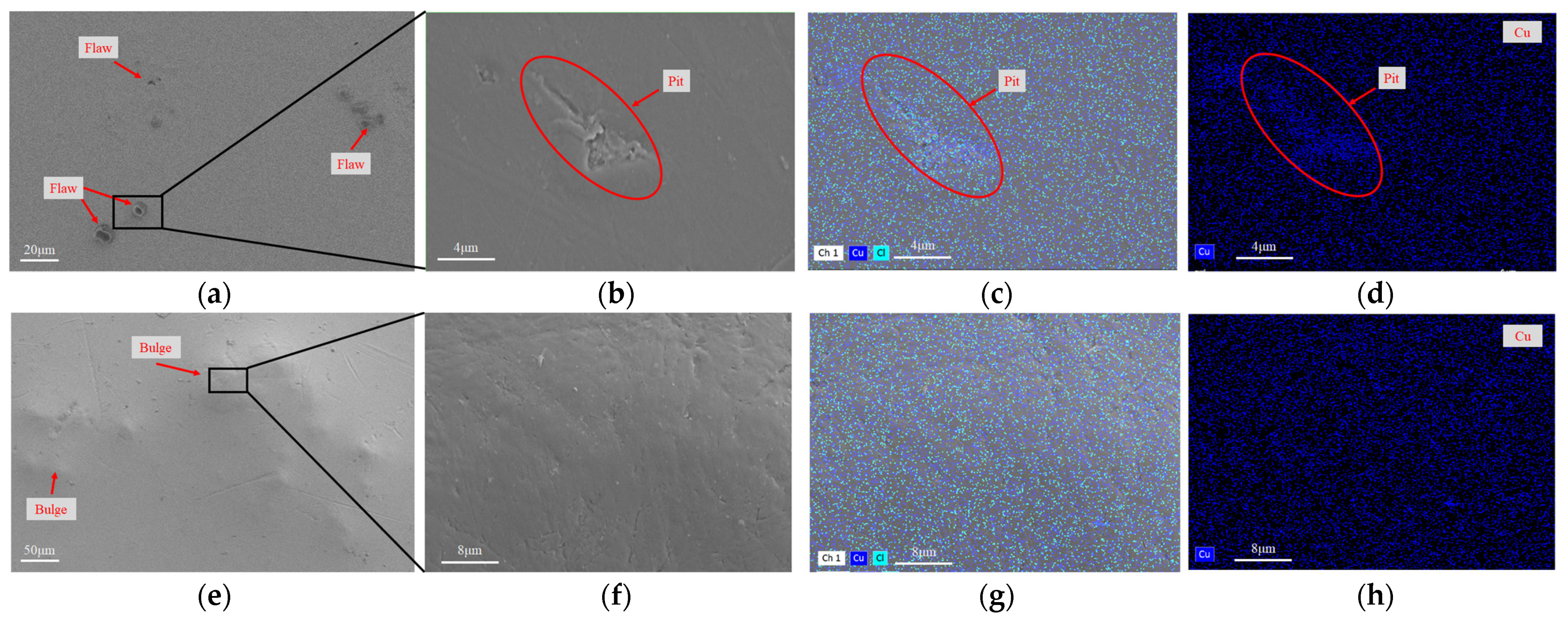
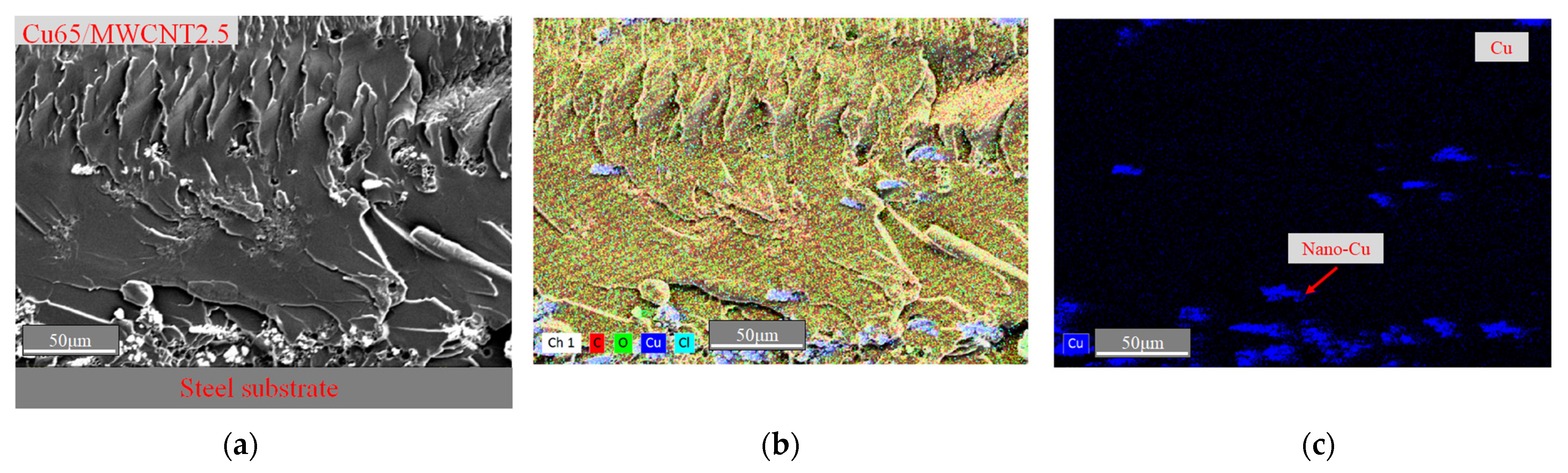
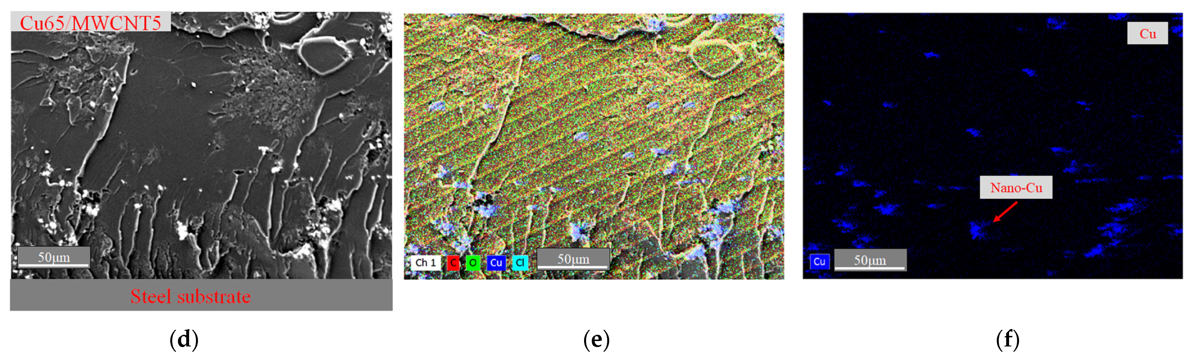
3.1. Morphology of Cu/MWCNT Epoxy Coatings

Figure 1 shows the SEM images and EDS mappings of the specimens after 30 days in the 3.5 wt % NaCl solution. Figure 1a displays the microstructures of the surface of coating Cu65/MWCNT2.5 after 30 days of immersion in the 3.5 wt % NaCl solution. The surface of the Cu65/MWCNT2.5 specimen showed several flaws ranging from 5 to 10 µm in diameter. Upon further magnification of the box in Figure 1a, pits were observed, as depicted in Figure 1b. The EDS mapping was performed on the surface zone of Figure 1b to obtain Figure 1c. The EDS mapping of Figure 1c separated the Cu elements to produce Figure 1d, indicating that nano-Cu was clustered in the pits. This clustering of nano-Cu led to defects between the epoxy and nano-Cu [37]. These defects subsequently propagated due to the continuous hydrolysis of the epoxy surrounding the defects during immersion in a 3.5 wt % NaCl solution [38], resulting in pit formation.
Figure 1e displays the microstructures of the surface of coating Cu65/MWCNT5 after 30 days of immersion in the 3.5 wt % NaCl solution. Compared with Figure 1a, Figure 1e shows that there were no flaws but many bulges on its surface. This is due to the high addition of MWCNTs forming a dense physical barrier structure [39], resulting in increased fracture toughness of the coating and preventing the formation of flaws. Further magnification of the box in Figure 1e is shown in Figure 1f, and it revealed a rough but crack-free surface, as shown in Figure 1f. The surface zone of Figure 1f was performed by using the EDS mapping analysis, as shown in Figure 1g. The distribution of Cu elements as shown in Figure 1h, indicated the uniform distribution of the nano-Cu element within the coating. This was attributed to the effects of the adsorption of hydroxylated MWCNTs on Cu nanoparticles [40]. It indicated an even dispersion of nano-Cu within the epoxy coating. Cu65/MWCNT5 exhibited fewer defects compared to Cu65/MWCNT2.5, suggesting superior corrosion resistance in the former.
Figure 2a,d show SEM images of the cross-section of the Cu65/MWCNT2.5 and Cu65/MWCNT5 epoxy coating peeling from the steel surface after 30 days of immersion in a 3.5 wt % NaCl solution, respectively. In comparison to Figure 2d, Figure 2a reveals a substantial number of holes in the coating near the steel substrate interface. This suggests that increasing the weight percentage of MWCNTs from 2.5 to 5% strengthens the bond between the epoxy coating and the steel substrate. The cross-section of the coating component in Figure 2a,d was obtained using EDS mapping analysis. The distribution of C, O, Cu and Cl elements was detected, and is shown in Figure 2b,e. The distribution of C, O and Cl elements in Figure 2b,e was excluded, and the distribution of Cu elements is shown in Figure 2c,f. Figure 2c demonstrates the distribution of Cu through the cross-section of Cu65/MWCNT2.5. It was observed that most Cu nanoparticles clustered towards the bottom of the coating. This resulted in low surface conductivity due to the nonconductive epoxy resin present on the top surface. Figure 2f displays the copper distribution in the cross-section of the Cu65/MWCNT5 specimen. Compared to the distribution of nano-Cu in the epoxy coating of Cu65/MWCNT5 in Figure 2c, nano-Cu was distributed through the coating more evenly. These findings suggest that the addition of MWCNTs significantly influences the distribution of nano-Cu within the epoxy coating. The hydroxylated MWCNTs have an adsorption effect on the nano-Cu [34], and prevent the nano-Cu from clustering at the bottom of the coating which, as a result, improves the coating surface’s conductivity.

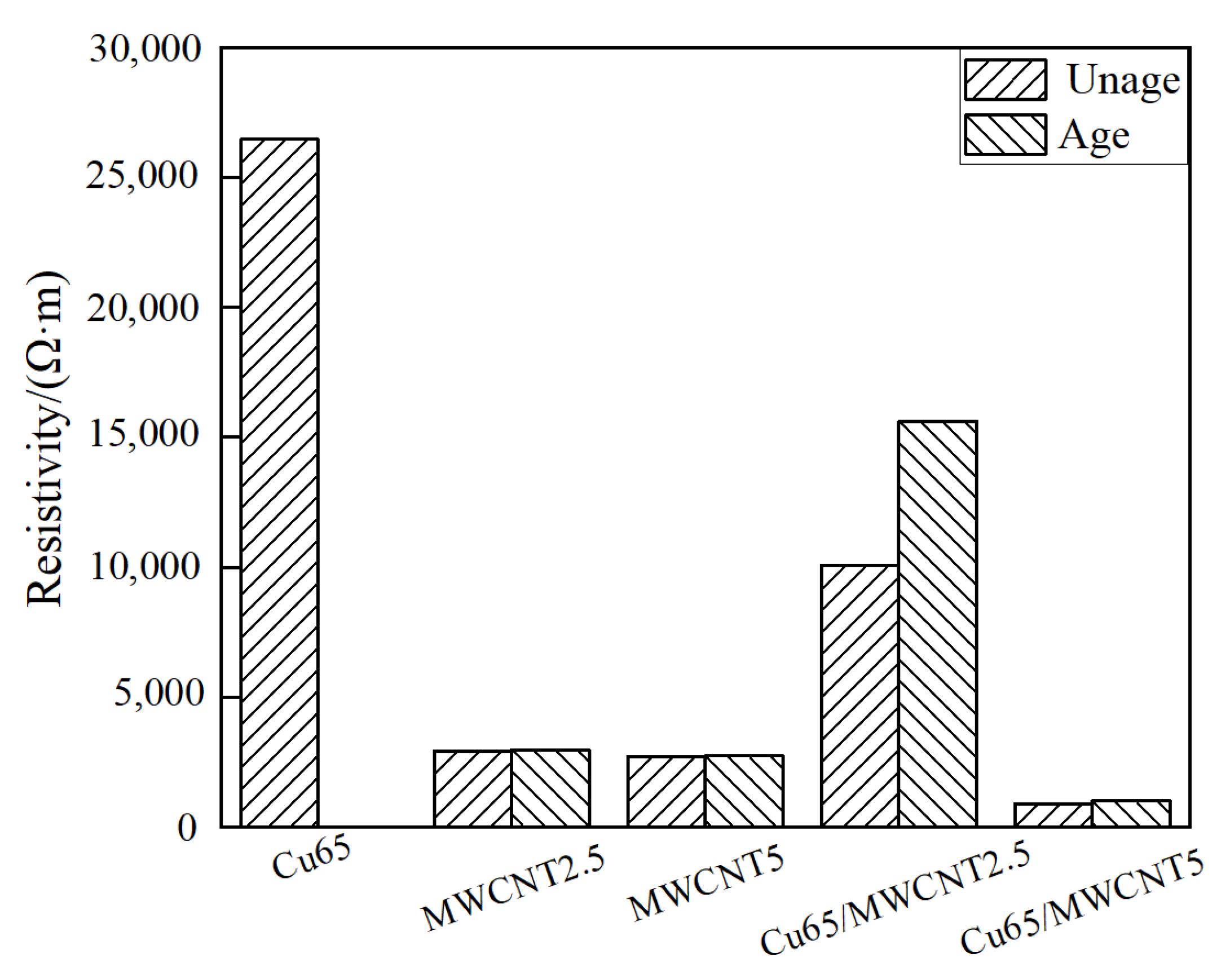
3.2. Electrical Conductivity

Table 3 lists the resistivity of the control specimen and the coatings immersed in the 3.5 wt % NaCl solution for 30 days. In the case of unaged specimens, the resistivity of the nano-Cu epoxy coating was one order of magnitude higher than that of the hydroxylated MWCNT epoxy coating. The density of the nano-Cu was higher than that of the epoxy resin, and the nano-Cu agglomerated at the bottom of the coating. Thus, the epoxy resin layer separated from the mixed layer of nano-Cu and epoxy resin. The presence of the epoxy resin layer results in low conductivity from the nano-Cu epoxy coating. The hydroxylated MWCNTs dispersed more uniformly than the Cu nanoparticles in the epoxy resin. The hydroxylated MWCNTs with a distance of less than 1.4 nm were close enough to form conductive junctions, allowing electrons to transfer between the junctions through a tunneling mechanism [41]. The resistivity of the MWCNT epoxy coating decreased with increasing hydroxylated MWCNT content. The resistivity of specimen MWCNT2.5 was 8.16% higher than that of coating MWCNT5. The higher the hydroxylated MWCNT content, the greater the number of conductive junctions formed.
The resistivity of specimen Cu65/MWCNT5 declined one order of magnitude compared to that of coating MWCNT5. A high content of hydroxylated MWCNTs improved the dispersion of nano-Cu in the coating. In fact, since hydroxylated MWCNTs can adsorb nano-Cu [42], adding hydroxylated MWCNTs enhances the uniform dispersion of the nano-Cu in the resin matrix. The high density of nano-Cu and the large mean free path of hydroxylated MWCNTs led to a higher conductivity in the nano-Cu/MWCNT epoxy coatings than that of the hydroxylated MWCNT epoxy coating and nano-Cu epoxy coating [43]. When the content of hydroxylated MWCNTs drops from 5.0 to 2.5%, the resistivity of the nano-Cu/MWCNT epoxy coating increases. For example, the resistivity of specimen Cu65/MWCNT2.5 was one order of magnitude higher than that of specimen MWCNT2.5, which was due to the high density of nano-Cu deposited at the bottom of the coating with hydroxylated MWCNTs, thickening the nonconductive epoxy resin on the surface and increasing the surface resistivity.
Figure 3 illustrates the variation in conductivity of the steel coatings both prior to and following the 30-day immersion in a 3.5 wt % NaCl solution. The nano-Cu epoxy coating exhibited a loss in surface electrical conductivity compared to the unaged specimens, due to the oxidation of nano-Cu into nonconductive CuO [22], which resulted in a surface coating square resistance exceeding 100 MΩ/□. In contrast, the resistivity of the hydroxylated MWCNT epoxy coating remained stable after 30 days of immersion in the 3.5 wt % NaCl solution. This is attributable to the superior corrosion resistance and stable conductivity of hydroxylated MWCNTs [44]. The resistivity of the Cu65/MWCNT2.5 specimens decreased by 55.5%. Previous SEM observations indicated that nano-Cu aggregated in Cu65/MWCNT2.5, and these aggregated nano-Cu sites became the weak areas in the coating. These sites were easily oxidized into nonconductive CuO, leading to the breakdown of the conductive grid and an increase in the surface coating resistance [19]. However, the resistivity of the Cu65/MWCNT5 specimens decreased by only 10.7%. This is due to the hydroxylated MWCNTs forming a compact structure that prevents coating defects [39] and inhibits the oxidation of nano-Cu, thus maintaining the coating’s electrical conductivity.

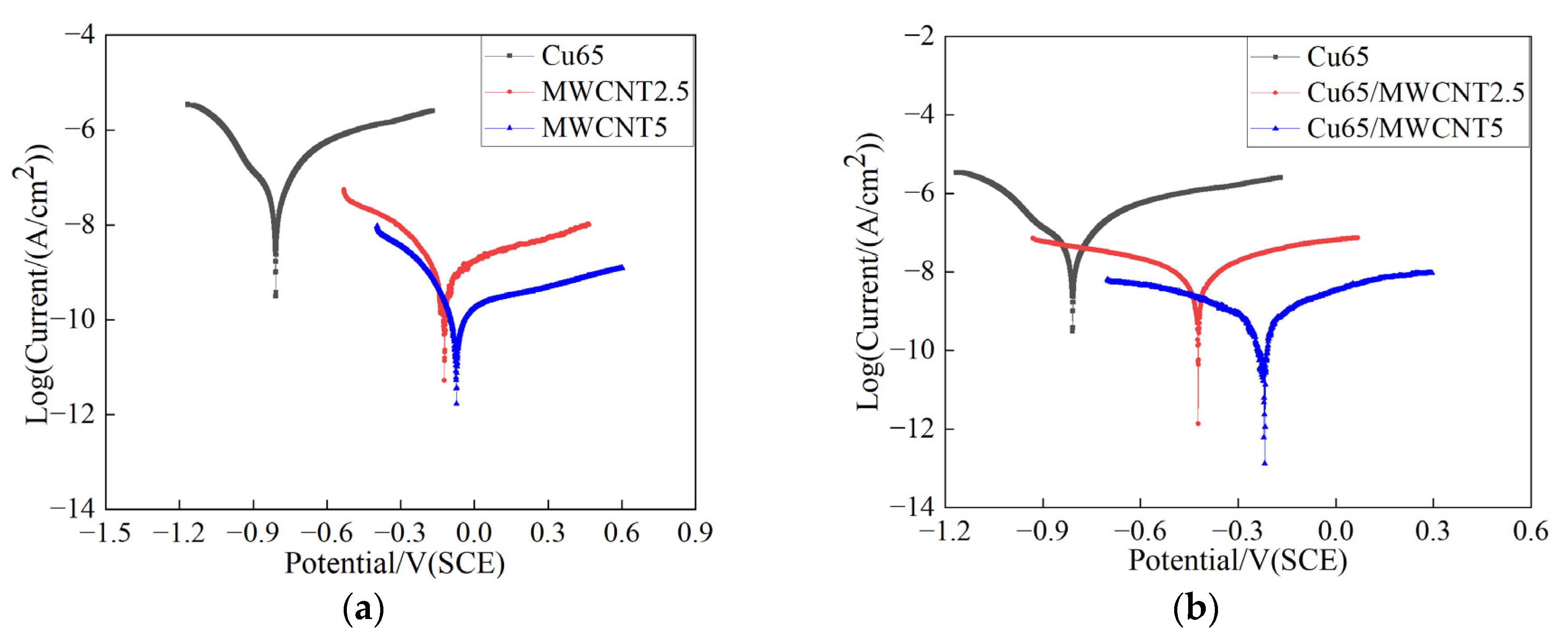
3.3. Polarization Curves

Figure 4 presents the Tafel polarization curve of the anticorrosive conductive coating following 30 days of immersion in a 3.5 wt % NaCl solution. The anticorrosion property of the coating is evaluated by the corrosion rate of the steel bars (CR, mm/year) [45], as expressed in Equation (2). The corrosion rate is determined by the corrosion current density (Icorr), which is obtained from the polarization curve by fitting the Tafel extrapolation method and Stern–Geary formula, as given in Equations (3) and (4). The corrosion rates and fitted parameters of the Tafel extrapolation method and the Stern–Geary formula are listed in Table 4.
CR = A × I corr n × F × ρ = 0.116 × I corr
where A represents the atomic weight of iron (55.85 g/mol); n, F, and ρ denote the charge transfer number of the chemical reaction, the Faraday constant (96,485.33 C/mol), and the density of iron (7.86 g/cm3), respectively.
η = a ± β log i
where η represents overpotential, a and β are constants, and i is the current density.
I corr = β a + β c ( 2.303 × R p ) × ( β a × β c )
where βa and βc denote the anode and cathode polarization slopes, respectively, which can be obtained by Equation (3); Rp is the polarization resistance.
Figure 4a reveals that the corrosion current of the Cu/MWCNT epoxy coating was significantly lower than that of the epoxy coating (10−9–10−6 A/cm2 [46]). This was ascribed to the addition obstructing the entry of corrosive ions and extending the corrosion path of the epoxy coating [47]. The nano-Cu epoxy coating had a higher corrosion current density and smaller corrosion potential than the other specimens, implying that the anticorrosion property of the nano-Cu epoxy coating is lower than that of the hydroxylated MWCNT epoxy coating. Table 4 shows that the CR of the Cu65 coating is one and two orders of magnitude higher than that of coatings MWCNT2.5 and MWCNT5, respectively. Defects or disruptions in the nano-Cu epoxy may facilitate the entry of corrosive media into the coating, thereby reducing its corrosion resistance [29]. The hydroxylated MWCNTs, however, form a physical barrier layer at the coating–electrolyte interface that exhibits excellent corrosion resistance and low chemical reactivity [39]. The corrosion rate of coating MWCNT5 was one order of magnitude lower than that of specimen MWCNT2.5 because a higher content of MWCNTs forms a denser structure in the coating, leading to a further improvement in corrosion resistance.
Figure 4b shows that adding hydroxylated MWCNTs to nano-Cu epoxy coatings can improve the anticorrosion property of the coating and shift its corrosion potential toward that of precious metals. The corrosion resistance of the Cu65/MWCNT epoxy coating improves with the increase in the hydroxylated MWCNT content. Table 4 demonstrates that the corrosion rate (CR) of the Cu65/MWCNT2.5 coating was 1.9% lower than that of specimen Cu65. At the same time, the CR of coating Cu65/MWCNT5 was three orders of magnitude lower than that of specimen Cu65, indicating that hydroxylated MWCNTs could have a remarkable effect on the anticorrosion property of the Cu/MWCNT epoxy coatings. At a low content of hydroxylated MWCNTs, the nano-Cu aggregates form weak regions in the coating. On the other hand, when the hydroxylated MWCNTs are abundant, their large surface area prevents the oxidation of the copper nanoparticles. The uniform distribution of MWCNTs inhibits local nano-Cu corrosion and enhances uniform corrosion, promoting corrosion resistance [48].
In addition, the corrosion rate of coating Cu65/MWCNT5 was 41.59% lower than that of specimen MWCNT5, which indicates the interactions between hydroxylated MWCNTs and nano-Cu. The hydroxylated MWCNTs increase the toughness of the coating [49]; the oxidation of the copper nanoparticles prevents the coating from cracking and further fills in the pores in the MWCNT epoxy coating, resulting in a longer corrosion path and a denser coating.

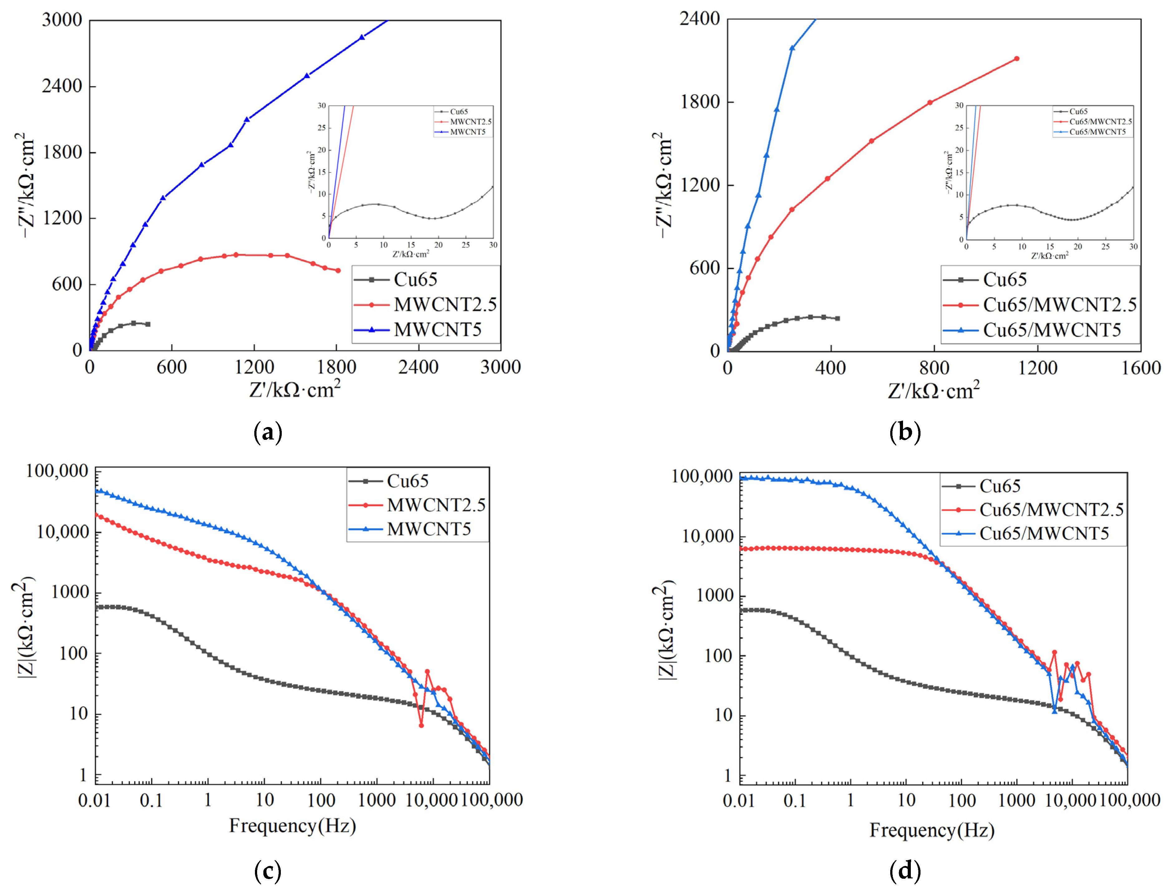
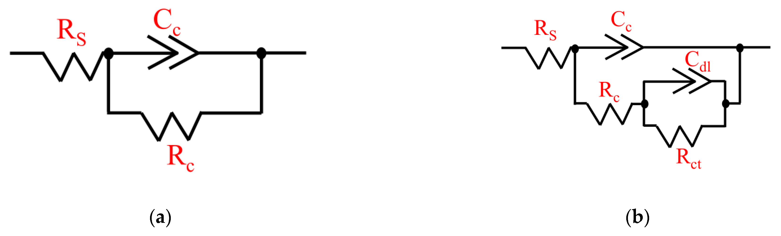
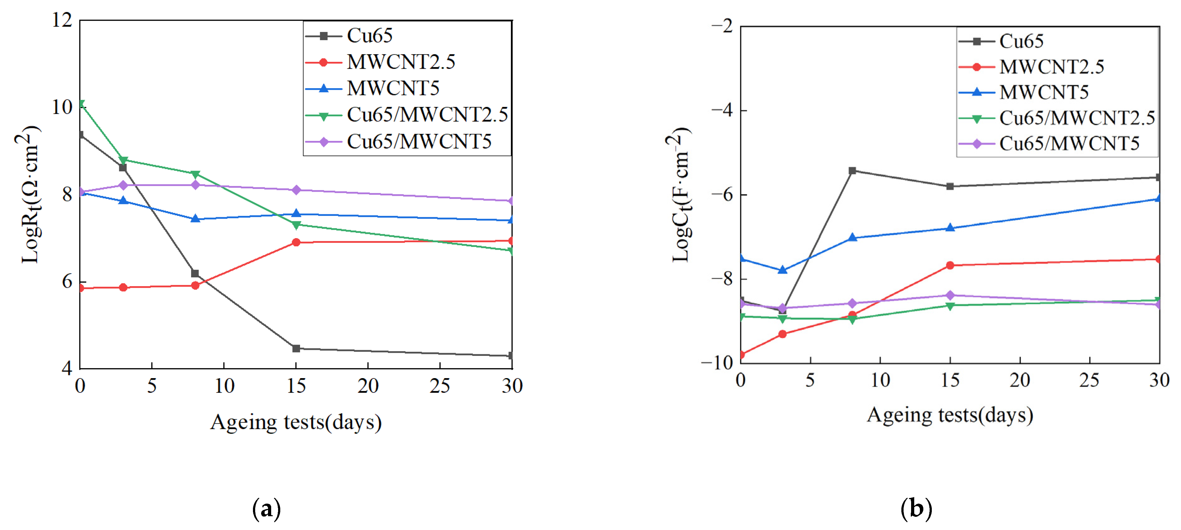
3.4. Electrochemical Impedance Spectroscopy

Figure 5 plots the Nyquist curves of the coatings immersed in 3.5 wt % NaCl solution for 30 days. Compared to the other coatings, the curve of specimen Cu65 had two semicircles, which indicated that the corrosive medium penetrated the coating and corroded the steel bars. Figure 5a shows that the capacitance arc diameter of the MWCNT epoxy coating was much higher than that of the nano-Cu epoxy coating. It has been reported that the diameter of the semicircle represents the impedance of the coating [50]. Thus, the hydroxylated MWCNT epoxy coating had much better charge-transfer resistance than the nano-Cu epoxy coating, proving that the MWCNT epoxy coating had better anticorrosion properties than the nano copper epoxy coating. The capacitance arc diameter of the MWCNT epoxy coating increased with the MWCNT content. Hence, the capacitance arc diameter of the MWCNT5 coating was much larger than that of coating MWCNT2.5, implying that the anticorrosion property of the MWCNT epoxy coatings increases with the rise in MWCNT content. Figure 5b shows the effects of the mixture of nano-Cu and MWCNTs on the charge-transfer resistance of the coatings. The capacitance arc diameter of specimen Cu65/MWCNT was much larger than that of coating Cu65 and increased significantly as the MWCNT content rose. This result was similar to that of the polarization curve, indicating that adding MWCNTs to the nano-Cu epoxy coating effectively increases the charge-transfer resistance and improves the anticorrosion property of the coating.
The low-frequency impedance modulus ( Z 0.01 Hz ) was employed to evaluate the anticorrosion property of the coatings [51]. The Bode plots made it possible to directly compare the ( Z 0.01 Hz ) of different coatings. Figure 5c illustrates that the impedance moduli ( Z 0.01 Hz ) for specimens Cu65, MWCNT2.5, and MWCNT5 were 5.73 × 10² kΩ·cm2, 1.94 × 10⁴ kΩ·cm2, and 4.77 × 10⁴ kΩ·cm2, respectively. The impedance modulus of the MWCNTs epoxy coatings was two orders of magnitude higher than that of the nano-Cu epoxy coating, signifying that the MWCNT epoxy coatings exhibited superior anticorrosion properties. Figure 5d reveals that the impedance moduli ( Z 0.01 Hz ) of specimens Cu65/MWCNT2.5 and Cu65/MWCNT5 were 6.35 × 10³ kΩ·cm2 and 9.67 × 10⁴ kΩ·cm2, respectively. Notably, the impedance modulus of coating Cu65/MWCNT2.5 was 67.3% lower than that of specimen MWCNT2.5, while the impedance modulus of specimen Cu65/MWCNT5 was 102.7% higher than that of coating MWCNT5. The presence of MWCNTs in the Cu65/MWCNT epoxy coatings significantly affected the low-frequency impedance modulus. At an MWCNT content of 2.5%, the nano-Cu became the coating’s weak region, and corrosive ions created a corrosion path through the corrosion of the copper nanoparticles. However, when the MWCNT content rose to 5%, they formed a dense structure that hindered the entry of corrosive ions, and nano-Cu filled the pores between MWCNTs, thus extending the corrosion paths.
Figure 6 illustrates an electrochemical equivalent circuit model for analysis of the EIS diagram to further analyze the corrosion behavior of the coatings. Rs, Rc, and Rct represent the solution, coating, and charge-transfer resistance, respectively. Cc and Cdl indicate the coating capacitance and the double-layer capacitance, respectively. Previous research results [52,53] are utilized in Figure 6a to fit a Nyquist graph with a single semicircle, and Figure 6b to fit a Nyquist diagram with two semicircles. All the fitted parameters are listed in Table 5. Total resistance (Rt) and total capacitance (Ct) were calculated according to the fitted results to analyze the effect of the anticorrosive coating on preventing the corrosion of the steel bars, as expressed in Equations (5) and (6) [54].
Rt = Rc + Rct
Ct = Cc + Cdl
Figure 7 represents the Rt and Ct of the specimens in the 3.5 wt % NaCl solution. Figure 7a shows that the Rt of coatings Cu65 and Cu65/MWCNT2.5 decreased with an extended immersion period. This is because the nano-Cu in the coating oxidizes into CuO during immersion in the NaCl solution, which forms a gap between the CuO and the epoxy, allowing the charge to directly penetrate the coating and infiltrate the matrix. The Rt of specimen Cu65/MWCNT2.5 declined more slowly than that of coating Cu65 as the immersion period lengthened, due to the dense structure formed by the corrosion-resistant MWCNTs which inhibited the charge transfer in the coating. Interestingly, the Rt of coating MWCNT2.5 also diminished with an extended immersion period. This is because the low addition (2.5%) MWCNT epoxy coating behaved similarly to a pure epoxy coating at the initial corrosion stage [53]. As corrosion progressed, the MWCNTs increasingly obstruct the corrosive ions, leading to an extension of the corrosion path and an increase in coating resistance. The Rt of coatings MWCNT5 and Cu65/MWCNT5 remained high, with their final charge-transfer resistance exceeding that of the other coatings. This is attributable to the dense structure formed by the high addition MWCNTs. This structure effectively blocks the entry of the corrosive medium, prevents the oxidation of nano-Cu, and enhances the coating’s toughness, thus inhibiting crack formation and charge transfer.
Figure 7b demonstrates that the Ct of specimens MWCNT2.5 and MWCNT5 increased as the immersion period extended because hydroxylated MWCNTs and epoxy resin are hydrophilic, and the constant intrusion of water molecules into the coating enlarged the dielectric constant [55]. The Ct of specimen Cu65 suddenly rose after 10 days of immersion in the NaCl solution because the corrosive medium invades the interface between the coating and the substrate. The opening of corrosion channels promotes water permeability and increases the dielectric constant of the coating. The Ct of coatings Cu/MWCNT2.5 and Cu/MWCNT5 remained stable during the 30 days of immersion in the NaCl solution because the compact structure formed by the MWCNTs prevented the medium from corroding the copper nanoparticles. The nano-Cu also blocked the diffusion of water molecules, so the dielectric constant of the coating remained stable. These results indicate that the Cu/MWCNT epoxy coatings have better barrier properties than the Cu epoxy or MWCNT epoxy coatings.

4. Conclusions

This study explored the conductivity and anticorrosion properties of Cu/MWCNT epoxy coatings on a steel substrate. The effects of MWCNT content on the conductivity and anticorrosion properties of Cu/MWCNT epoxy coatings were evaluated and compared with nano-Cu epoxy and MWCNT epoxy coatings. The influence of the nano-Cu and hydroxylated MWCNT ratio on the dispersion within the Cu/MWCNT epoxy coatings was analyzed, and the surface conductivity and anticorrosion behavior of Cu/MWCNT epoxy coatings was hypothesized. Based on the above results and discussions, several conclusions were drawn:
  • The presence of a high content of MWCNTs (5%) promoted the dispersion of nano-Cu within the epoxy coating, effectively preventing the formation of coating defects.
  • As the MWCNT content increased, the resistivity of the Cu/MWCNT epoxy coatings decreased. Specimen Cu65/MWCNT2.5 exhibited higher resistivity than coating MWCNT2.5, while specimen Cu65/MWCNT5 displayed lower resistivity than coating MWCNT5.
  • By incorporating MWCNTs, the surface resistance stability of nano-Cu epoxy coating can be enhanced. After being immersed in a 3.5 wt % NaCl solution for 30 days, the resistivity of Cu65/MWCNT5 only increased by 10.7%.
  • The Tafel and EIS results were in agreement. The epoxy coating comprising 5% hydroxylated MWNCTs and 65% nano-Cu exhibited the most robust anticorrosion properties on the steel substrate, with a corrosion current of 0.0413 nA/cm², a corrosion rate of 4.79 × 10⁷ mm/year, and an impedance of 9.67 × 10⁴ kΩ·cm².

Author Contributions

Formal analysis, data curation, visualization, writing—original draft, Y.Y.; supervision, investigation, writing—review and editing, M.L.; conceptualization, methodology, writing—review and editing, resources, funding acquisition, Y.P. All authors have read and agreed to the published version of the manuscript.

Funding

The authors gratefully acknowledge the financial support from the National Natural Science Foundation of China [grant numbers: 51908507, 52278280], the Scientific Research Fund of Zhejiang Provincial Education Department [grant number: Y202250470], and the Zhejiang Provincial Natural Science Foundation project number [grant number: LY19E080029].

Institutional Review Board Statement

Not applicable.

Informed Consent Statement

Not applicable.

Data Availability Statement

Some or all of the data, models, or codes that support the findings of this study are available from the corresponding author upon reasonable request.

Acknowledgments

The authors would like to thank Zhejiang Sci-Tech University for the support of this project.

Conflicts of Interest

The authors declare no conflict of interest.

References

  1. Alhozaimy, A.; Hussain, R.R.; Al-Negheimish, A. Electro-chemical investigation for the effect of rebar source and surface condition on the corrosion rate of reinforced concrete structures under varying corrosive environments. Constr. Build. Mater. 2020, 244, 118317. [Google Scholar] [CrossRef]
  2. Soufeiani, L.; Foliente, G.; Nguyen, K.T.; San Nicolas, R. Corrosion protection of steel elements in façade systems–A review. J. Build. Eng. 2020, 32, 101759. [Google Scholar] [CrossRef]
  3. Qu, F.; Li, W.; Dong, W.; Tam, V.W.; Yu, T. Durability deterioration of concrete under marine environment from material to structure: A critical review. J. Build. Eng. 2021, 35, 102074. [Google Scholar] [CrossRef]
  4. Xian, G.; Guo, R.; Li, C.; Hong, B. Mechanical properties of carbon/glass fiber reinforced polymer plates with sandwich structure exposed to freezing-thawing environment: Effects of water immersion, bending loading and fiber hybrid mode. Mech. Adv. Mater. Struct. 2022, 30, 814–834. [Google Scholar] [CrossRef]
  5. Lyon, S.B.; Bingham, R.; Mills, D.J. Advances in corrosion protection by organic coatings: What we know and what we would like to know. Prog. Org. Coat. 2017, 102, 2–7. [Google Scholar] [CrossRef] [Green Version]
  6. Kumar, A.; Kumar, K.; Ghosh, P.K.; Yadav, K. MWCNT/TiO2 hybrid nano filler toward high-performance epoxy composite. Ultrason. Sonochemistry 2018, 41, 37–46. [Google Scholar] [CrossRef]
  7. Hu, Q.; Chen, Z.; Xi, L.; Wang, X.; Wang, H. The application of epoxy resin coating in grounding grid. In IOP Conference Series: Materials Science and Engineering; IOP Publishing: Bristol, UK, 2018; p. 012110. [Google Scholar]
  8. Zhang, C.; Liao, Y.; Gao, X.; Zhao, J.; Yuan, Y.; Liao, R. Research advances of soil corrosion of grounding grids. Micromachines 2021, 12, 513. [Google Scholar] [CrossRef] [PubMed]
  9. Chen, W.; Bi, R.; Wang, J.; Chen, H. Review of grounding grids corrosion diagnosis. Int. J. Comput. Electr. Eng. 2013, 5, 309. [Google Scholar] [CrossRef] [Green Version]
  10. Liang, G. The research of the power plant and substation grounding network reconstruction Inner Mongolia region. In Proceedings of the 2014 China International Conference on Electricity Distribution (CICED), Shenzhen, China, 23–26 September 2014; pp. 388–395. [Google Scholar]
  11. Ranjith, R.; Rai, V.; Temizel, C. State-of-the-art materials in petroleum facilities and pipelines. In Sustainable Materials for Oil and Gas Applications; Elsevier: Amsterdam, The Netherlands, 2021; pp. 207–246. [Google Scholar]
  12. Hu, H.; Luo, R.; Fang, M.; Zeng, S.; Hu, F. A new optimization design for grounding grid. Int. J. Electr. Power Energy Syst. 2019, 108, 61–71. [Google Scholar] [CrossRef]
  13. Shen, W.; Feng, L.; Liu, X.; Luo, H.; Liu, Z.; Tong, P.; Zhang, W. Multiwall carbon nanotubes-reinforced epoxy hybrid coatings with high electrical conductivity and corrosion resistance prepared via electrostatic spraying. Prog. Org. Coat. 2016, 90, 139–146. [Google Scholar] [CrossRef]
  14. Aradhana, R.; Mohanty, S.; Nayak, S.K. A review on epoxy-based electrically conductive adhesives. Int. J. Adhes. Adhes. 2020, 99, 102596. [Google Scholar] [CrossRef]
  15. Stewart, I.E.; Ye, S.; Chen, Z.; Flowers, P.F.; Wiley, B.J. Synthesis of Cu–Ag, Cu–Au, and Cu–Pt core–shell nanowires and their use in transparent conducting films. Chem. Mater. 2015, 27, 7788–7794. [Google Scholar] [CrossRef]
  16. Hjortstam, O.; Isberg, P.; Söderholm, S.; Dai, H. Can we achieve ultra-low resistivity in carbon nanotube-based metal composites? Appl. Phys. A 2004, 78, 1175–1179. [Google Scholar] [CrossRef]
  17. Dekker, C. Carbon nanotubes as molecular quantum wires. Phys. Today 1999, 52, 22–30. [Google Scholar] [CrossRef]
  18. Jayathilaka, W.; Chinnappan, A.; Ramakrishna, S. A review of properties influencing the conductivity of CNT/Cu composites and their applications in wearable/flexible electronics. J. Mater. Chem. 2017, 5, 9209–9237. [Google Scholar] [CrossRef]
  19. Wang, Y.; Wang, X.; Cao, X.; Gong, S.; Xie, Z.; Li, T.; Wu, C.; Zhu, Z.; Li, Z. Effect of nano-scale Cu particles on the electrical property of CNT/polymer nanocomposites. Compos. Part A: Appl. Sci. Manuf. 2021, 143, 106325. [Google Scholar] [CrossRef]
  20. Chai, Y.; Chan, P.C. High electromigration-resistant copper/carbon nanotube composite for interconnect application. In Proceedings of the 2008 IEEE International Electron Devices Meeting, San Francisco, CA, USA; 5–17 December 2008; IEEE: Piscataway, NJ, USA, 2008; pp. 1–4. [Google Scholar]
  21. Shi, X.; Nguyen, T.A.; Suo, Z.; Liu, Y.; Avci, R. Effect of nanoparticles on the anticorrosion and mechanical properties of epoxy coating. Surf. Coat. Technol. 2009, 204, 237–245. [Google Scholar] [CrossRef]
  22. Navik, R.; Ding, X.; Huijun, T.; Zhao, Y. Facile synthesis of highly oxidation stable nanosilver-coated copper nanowires for transparent flexible electrodes. Ind. Eng. Chem. Res. 2020, 60, 263–272. [Google Scholar] [CrossRef]
  23. Cubides, Y.; Su, S.S.; Castaneda, H. Influence of zinc content and chloride concentration on the corrosion protection performance of zinc-rich epoxy coatings containing carbon nanotubes on carbon steel in simulated concrete pore environments. Corrosion 2016, 72, 1397–1423. [Google Scholar] [CrossRef]
  24. Jeon, H.; Park, J.; Shon, M. Corrosion protection by epoxy coating containing multi-walled carbon nanotubes. J. Ind. Eng. Chem. 2013, 19, 849–853. [Google Scholar] [CrossRef]
  25. Fu, S.; Chen, X.; Liu, P.; Liu, W.; Liu, P.; Zhang, K.; Chen, H. Electrodeposition and properties of composites consisting of carbon nanotubes and copper. J. Mater. Eng. Perform. 2018, 27, 5511–5517. [Google Scholar] [CrossRef]
  26. Mohammed, M.M.; Elsayed, E.M.; El-Kady, O.A.; Alsaleh, N.A.; Elsheikh, A.H.; Essa, F.A.; Ahmadein, M.; Djuansjah, J. Electrochemical Behavior of Cu-MWCNT Nanocomposites Manufactured by Powder Technology. Coatings 2022, 12, 409. [Google Scholar] [CrossRef]
  27. Song, R.; Zhang, S.; He, Y.; Li, H.; Fan, Y.; He, T.; Zhang, Y.; Xiang, Y.; Zhang, H. Effect of H-MWCNTs addition on anti-corrosion performance and mechanical character of Ni-Cu/H-MWCNTs composite coatings prepared by pulse electrodeposition technique. Colloids Surf. A: Physicochem. Eng. Asp. 2021, 630, 127519. [Google Scholar] [CrossRef]
  28. Shukla, A.; Nayan, N.; Murty, S.; Sharma, S.; Chandran, P.; Bakshi, S.R.; George, K.M. Processing of copper–carbon nanotube composites by vacuum hot pressing technique. Mater. Sci. Eng. A 2013, 560, 365–371. [Google Scholar] [CrossRef]
  29. Zhu, Z.; Kang, S.; Chen, H.; Zhao, Q.; Huo, Z.; Li, P.; Cao, Q.; Lu, C. Preparation and properties of CNTs-Cu hybrids/epoxy superhydrophobic and anticorrosive coatings. J. Ind. Eng. Chem. 2023, 119, 605–618. [Google Scholar] [CrossRef]
  30. GB/T 1499.1-2017; State General Administration of the People’s Republic of China. Steel for the Reinforcement of Concrete—Part 1: Hot Rolled Plain Bars. China Standard Press: Beijing, China, 2017.
  31. Dang, Z.-M.; Zhang, B.; Li, J.; Zha, J.-W.; Hu, G.-H. Copper particles/epoxy resin thermosetting conductive adhesive using polyamide resin as curing agent. Appl. Polym. Sci. 2012, 126, 815–821. [Google Scholar] [CrossRef]
  32. Zhang, F.; Qian, H.; Wang, L.; Wang, Z.; Du, C.; Li, X.; Zhang, D. Superhydrophobic carbon nanotubes/epoxy nanocomposite coating by facile one-step spraying. Surf. Coat. Technol. 2018, 341, 15–23. [Google Scholar] [CrossRef]
  33. Ranjbar, Z.; Yari, H. Modeling of electrical conductive graphene filled epoxy coatings. Prog. Org. Coat. 2018, 125, 411–419. [Google Scholar]
  34. Uthaman, A.; Lal, H.M.; Li, C.; Xian, G.; Thomas, S. Mechanical and water uptake properties of epoxy nanocomposites with surfactant-modified functionalized multiwalled carbon nanotubes. Nanomaterials 2021, 11, 1234. [Google Scholar] [CrossRef]
  35. Hirata, M.; Gotou, T.; Horiuchi, S.; Fujiwara, M.; Ohba, M. Thin-film particles of graphite oxide 1: High-yield synthesis and flexibility of the particles. Carbon 2004, 42, 2929–2937. [Google Scholar] [CrossRef]
  36. Qian, H.; Xu, Z.; Chen, S.; Liu, Y.; Yan, D. Silicon carbide/enamel composite coatings for steel corrosion protection: Microstructure, thermal expansion behavior, and anti-corrosion performance. Surf. Coat. Technol. 2022, 434, 128172. [Google Scholar] [CrossRef]
  37. Cui, C.Q.; Tay, H.; Chai, T.; Ggopalakrishan, R.; Lim, T. Surface Treatment of Copper for the Adhesion Improvement to Epoxy Mold Compounds, 1998 Proceedings. 48th Electronic Components and Technology Conference (Cat. No. 98CH36206); IEEE: Piscataway, NJ, USA, 1998; pp. 1162–1166. [Google Scholar]
  38. Ramezanzadeh, B.; Attar, M. Studying the corrosion resistance and hydrolytic degradation of an epoxy coating containing ZnO nanoparticles. Mater. Chem. Phys. 2011, 130, 1208–1219. [Google Scholar] [CrossRef]
  39. Alishahi, M.; Monirvaghefi, S.M.; Saatchi, A.; Hosseini, S.M. The effect of carbon nanotubes on the corrosion and tribological behavior of electroless Ni–P–CNT composite coating. Appl. Surf. Sci. 2012, 258, 2439–2446. [Google Scholar] [CrossRef]
  40. Gojny, F.H.; Wichmann, M.H.G.; Köpke, U.; Fiedler, B.; Schulte, K. Carbon nanotube-reinforced epoxy-composites: Enhanced stiffness and fracture toughness at low nanotube content. Compos. Sci. Technol. 2004, 64, 2363–2371. [Google Scholar] [CrossRef]
  41. Chen, X.-C.; Ren, K.-F.; Lei, W.-X.; Zhang, J.-H.; Martins, M.C.L.; Barbosa, M.A.; Ji, J. Self-healing spongy coating for drug “cocktail” delivery. ACS Appl. Mater. Interfaces 2016, 8, 4309–4313. [Google Scholar] [CrossRef]
  42. Park, M.; Kim, B.-H.; Kim, S.; Han, D.-S.; Kim, G.; Lee, K.-R. Improved binding between copper and carbon nanotubes in a composite using oxygen-containing functional groups. Carbon 2011, 49, 811–818. [Google Scholar] [CrossRef]
  43. Mandal, P.; Mondal, S.C. Investigation of Electro-Thermal property for Cu-MWCNT composite coating on anodized 6061 aluminium alloy. Appl. Surf. Sci. 2018, 454, 138–147. [Google Scholar] [CrossRef]
  44. Tian, J.; Li, C.; Xian, G. A layered superhydrophobic coating with excellent mechanical robustness and anti-corrosion performances. J. Mater. Res. Technol. 2022, 21, 4281–4298. [Google Scholar] [CrossRef]
  45. Zhu, Y.; Zhang, Z. Investigation of the anticorrosion layer of reinforced steel based on graphene oxide in simulated concrete pore solution with 3 wt.% NaCl. J. Build. Eng. 2021, 44, 103302. [Google Scholar] [CrossRef]
  46. Wang, F.; Feng, L.; Huang, Y.; Li, G.; Zhai, Z. Effect of coating process on the properties of multi-walled carbon nanotubes/waterborne polyurethane anticorrosive and conductive coating. AIP Adv. 2019, 9, 035241. [Google Scholar] [CrossRef] [Green Version]
  47. Ollik, K.; Lieder, M. Review of the application of graphene-based coatings as anticorrosion layers. Coatings 2020, 10, 883. [Google Scholar] [CrossRef]
  48. Chen, X.; Chen, C.; Xiao, H.; Cheng, F.; Zhang, G.; Yi, G. Corrosion behavior of carbon nanotubes–Ni composite coating. Surf. Coat. Technol. 2005, 191, 351–356. [Google Scholar] [CrossRef]
  49. Sharma, N.; Sharma, S.; Sharma, S.K.; Mahajan, R.L.; Mehta, R. Evaluation of corrosion inhibition capability of graphene modified epoxy coatings on reinforcing bars in concrete. Constr. Build. Mater. 2022, 322, 126495. [Google Scholar] [CrossRef]
  50. Li, J.; Gan, L.; Liu, Y.; Mateti, S.; Lei, W.; Chen, Y.; Yang, J. Boron nitride nanosheets reinforced waterborne polyurethane coatings for improving corrosion resistance and antifriction properties. Eur. Polym. J. 2018, 104, 57–63. [Google Scholar] [CrossRef]
  51. Ramezanzadeh, B.; Moghadam, M.M.; Shohani, N.; Mahdavian, M. Effects of highly crystalline and conductive polyaniline/graphene oxide composites on the corrosion protection performance of a zinc-rich epoxy coating. Chem. Eng. J. 2017, 320, 363–375. [Google Scholar] [CrossRef]
  52. Cai, G.; Xiao, S.; Deng, C.; Jiang, D.; Zhang, X.; Dong, Z. CeO2 grafted carbon nanotube via polydopamine wrapping to enhance corrosion barrier of polyurethane coating. Corros. Sci. 2021, 178, 109014. [Google Scholar] [CrossRef]
  53. Chen, S.; Wang, X.; Zhu, G.; Lu, Z.; Zhang, Y.; Zhao, X.; Hou, B. Developing multi-wall carbon nanotubes/Fusion-bonded epoxy powder nanocomposite coatings with superior anti-corrosion and mechanical properties. Colloids Surf. A Physicochem. Eng. Asp. 2021, 628, 127309. [Google Scholar] [CrossRef]
  54. Qu, L.; Wang, Q.; Xu, S.; Wang, N.; Shi, Z. Chloride corrosion resistance of double-layer anticorrosive coating in simulated concrete pore solution. Constr. Build. Mater. 2021, 295, 123682. [Google Scholar] [CrossRef]
  55. Liu, J.; Lei, Y.; Qiu, Z.; Li, D.; Liu, T.; Zhang, F.; Sun, S.; Chang, X.; Fan, R.; Yin, Y. Insight into the impact of conducting polyaniline/graphene nanosheets on corrosion mechanism of zinc-rich epoxy primers on low alloy DH32 steel in artificial sea water. J. Electrochem. Soc. 2018, 165, C878. [Google Scholar] [CrossRef]
Figure 1. The SEM micrographs and EDS mappings of specimens (ad) Cu65/MWCNT2.5 and (eh) Cu65/MWCNT5 following 30-day immersion in 3.5 wt % NaCl solution.
Coatings 13 01116 g001
Figure 2. The SEM-EDS of the full cross-section of specimens (ac) Cu65/MWCNT2.5 and (df) Cu65/MWCNT5 following 30-day immersion in the 3.5 wt % NaCl solution.
Coatings 13 01116 g002aCoatings 13 01116 g002b
Figure 3. Resistivity of different steel coatings before and after immersion in a 3.5 wt %NaCl solution for 30 days.
Coatings 13 01116 g003
Figure 4. The Tafel polarization curves of the (a) Cu epoxy or MWCNT epoxy coatings and (b) the anticorrosive conductive Cu/MWCNT epoxy coatings soaked in the 3.5 wt % NaCl solution for 30 days.
Coatings 13 01116 g004
Figure 5. The (a,b) Nyquist and (c,d) Bode plots from the EIS of the (a,c) Cu epoxy or MWCNT epoxy coatings and (b,d) the anticorrosive conductive Cu/MWCNT epoxy coatings soaked in the 3.5 wt % NaCl solution for 30 days.
Coatings 13 01116 g005
Figure 6. The equivalent circuit model used to fit the Nyquist diagram of (a) a single semicircle and (b) two semicircles.
Coatings 13 01116 g006
Figure 7. Comparing the (a) Rct and (b) Cc of the coatings immersed in the 3.5 wt % NaCl solution for 0–30 days.
Coatings 13 01116 g007
Table 1. Chemical composition of steel bar (wt. %).
Type of SteelCMnSiSPFe
HPB3000.210.630.350.0240.02198.765
Table 2. Mixing contents of the four components of the coating.
SpecimensMWCNTs (g)Cu (g)Epoxy (g)PVP (g)
MWCNT2.51.0-40.00.1
MWCNT52.0-40.00.2
Cu65-26.040.0-
Cu65/MWCNT2.51.026.040.00.1
Cu65/MWCNT52.026.040.00.2
Note: “MWCNT” and “Cu” indicate that the conductive medium consists of hydroxylated multi-walled carbon nanotubes and copper nanoparticles, respectively. The numbers 2.5, 5, and 65 denote the mass ratio of the conductive medium to the resin, i.e., 2.5, 5.0, and 65%, respectively. For instance, “Cu65/MWCNT2.5” represents a composite epoxy coating with a copper nanoparticle–resin mass ratio of 65% and a hydroxylated multi-walled carbon nanotube–resin mass ratio of 2.5%.
Table 3. The conductivity parameters of different coatings.
SpecimensThickness (µm)Square Resistance (MΩ/□)Resistivity (Ω·m)
Cu65-0D293 ± 1290.29426,456.142
MWCNT2.5-0D317 ± 179.2052917.985
MWCNT5-0D299 ± 99.0232697.877
Cu65/MWCNT2.5-0D310 ± 1232.47610,067.56
Cu65/MWCNT5-0D307 ± 142.933900.431
Cu65-30D293 ± 18--
MWCNT2.5-30D317 ± 69.3582966.486
MWCNT5-30D299 ± 129.1442734.056
Cu65/MWCNT2.5-30D310 ± 850.37215,615.32
Cu65/MWCNT5-30D307 ± 83.248997.136
Note: “Cu65-30D” failed to be measured due to square resistance exceeding the measuring range (100 MΩ/□).
Table 4. The Tafel polarization parameters.
SpecimensEcorr
(V(SCE))
Icorr (A/cm2)βa (mV)βc (mV)Corrosion Rate (mm/year)
Cu65−0.8084.98 × 10−8177.35169.035.78 × 10−4
MWCNT2.5−0.1221.17 × 10−9536.79191.251.36 × 10−5
MWCNT5−0.0727.07 × 10−111498191.788.20 × 10−7
Cu65/MWCNT2.5−0.4234.89 × 10−810972569.75.67 × 10−4
Cu65/MWCNT5−0.2184.13 × 10−1196.565104.194.79 × 10−7
Table 5. The fitted results of the electrochemical equivalent circuit.
SpecimenTimeRc (Ω·cm2)Cc (F·cm2)n1Rct (Ω·cm2)Cdl (F·cm2)n2Model
Cu653 h2.39 × 1093.12 × 10−90.87---(a)
3 days4.23 × 1081.78 × 10−90.93---(a)
8 days5.95 × 1046.01 × 10−130.971.47 × 1063.79 × 10−60.57(b)
15 days2.98 × 1044.52 × 10−90.869.59 × 1051.58 × 10−60.77(b)
30 days2.00 × 1041.83 × 10−90.957.12 × 1052.63 × 10−60.71(b)
MWCNT2.53 h7.26 × 1051.61 × 10−100.98---(a)
3 days7.50 × 1055.01 × 10−100.66---(a)
8 days8.36 × 1051.41 × 10−90.96---(a)
15 days8.16 × 1062.15 × 10−80.89---(a)
30 days8.77 × 1063.01 × 10−80.89---(a)
MMWCNT53 h1.13 × 1083.06 × 10−80.69---(a)
3 days7.22 × 1071.61 × 10−80.65---(a)
8 days2.76 × 1079.55 × 10−80.35---(a)
15 days3.65 × 1071.61 × 10−70.65---(a)
30 days2.60 × 1078.13 × 10−70.79---(a)
Cu65/MWCNT2.53 h1.30 × 10101.33 × 10−90.91---(a)
3 days6.39 × 1081.20 × 10−90.93---(a)
8 days3.07 × 1081.15 × 10−90.95---(a)
15 days2.09 × 1072.41 × 10−90.85---(a)
30 days5.23 × 1063.20 × 10−90.80---(a)
Cu65/MWCNT53 h1.16 × 1082.60 × 10−90.85---(a)
3 days1.66 × 1082.06 × 10−90.88---(a)
8 days1.69 × 1082.69 × 10−90.84---(a)
15 days1.31 × 1084.17 × 10−90.78---(a)
30 days7.29 × 1072.52 × 10−90.87---(a)
Disclaimer/Publisher’s Note: The statements, opinions and data contained in all publications are solely those of the individual author(s) and contributor(s) and not of MDPI and/or the editor(s). MDPI and/or the editor(s) disclaim responsibility for any injury to people or property resulting from any ideas, methods, instructions or products referred to in the content.

