Article

The Interplay Effects between Feed-Gas Composition and Bias Plasma Condition during Active-Screen Plasma Nitrocarburizing with a Solid Carbon Source

1
Institute of Materials Engineering, Technische Universität Bergakademie Freiberg, 09599 Freiberg, Germany
2
Center for Efficient High Temperature Processes and Materials Conversion, Technische Universität Bergakademie Freiberg, 09599 Freiberg, Germany
3
Leibniz Institute for Plasma Science and Technology (INP), 17489 Greifswald, Germany
*
Author to whom correspondence should be addressed.
Coatings 2023, 13(6), 1103; https://doi.org/10.3390/coatings13061103
Submission received: 25 April 2023 / Revised: 30 May 2023 / Accepted: 7 June 2023 / Published: 15 June 2023
(This article belongs to the Section Surface Characterization, Deposition and Modification)

Abstract

:
Recent technological development of utilizing an active screen made of solid carbon for plasma-assisted thermochemical diffusion treatments opens up new possibilities for control over the in situ generated treatment environment to guarantee reproducible treatment conditions and material responses. Until now, the investigations of active-screen plasma nitrocarburizing (ASPNC) using an active screen manufactured from solid carbon focused on the influence of a single treatment parameter variation on the material response. In this systematic study, experiments were conducted to vary the H2-N2 feed-gas composition while varying the bias plasma power. The experiments served to better understand a simultaneous variation in the mentioned parameters on the resulting treatment environment and material response during ASPNC of AISI 316L austenitic stainless steel. Therefore, nitriding and carburizing effects in the expanded austenite layer can be obtained. It is shown that an increased nitriding effect, i.e., nitrogen diffusion depth and content, was achieved in case of biased conditions and for H2-N2 feed-gas compositions with higher N2 amounts. On the contrary, an increased carburizing effect, i.e., carbon diffusion depth and content, was achieved in nonbiased conditions, independent from the H2-N2 feed-gas composition.

1. Introduction

The surface properties of conventionally used austenitic stainless steels often do not fully satisfy the desired characteristics in terms of sufficient surface hardness and wear resistance for the intended applications. Therefore, modification of these surface properties is required, aiming at the reliable performance and long lifetime of the components manufactured from such steels. Low-temperature plasma-assisted thermochemical diffusion treatments such as plasma nitriding (PN) [1,2], plasma carburizing (PC) [3,4,5] and plasma nitrocarburizing (PNC) [6] can be effectively applied to improve the surface hardness and wear resistance of austenitic stainless steels without negatively affecting their high general corrosion resistance [7,8]. Moreover, it has been shown that the pitting corrosion resistance to a variety of chloride-containing media improved significantly compared to untreated steels [9,10]. During such a low-temperature treatment, due to the low mobility of chromium (Cr) atoms as compared to the interstitial nitrogen (N) and/or carbon (C) atoms, formation of chromium nitride/carbide precipitates is kinetically suppressed [11,12]. This leads to the formation of a modified surface layer of a supersaturated solid solution of N and/or C atoms in the face-centred cubic (fcc) structure of austenite, known as “expanded austenite”, being free of chromium nitride/carbide precipitates [12]. In particular, PNC treatment of austenitic stainless steel results in a duplex-layer structure of expanded austenite due to the simultaneous incorporation of N and C atoms, which consists of a near-surface N-expanded austenite (γN) layer on top of a C-expanded austenite (γC) layer [13,14]. Due to the different nature of the C and N atoms, the properties of the generated duplex layer (γNC) can be different from pure-γN and pure-γC layers. For instance, with PN treatment, the hardness of the generated γN layer is higher, but the thickness is lower [15], whereas in PC treatment, the hardness of the γC layer is lower, but the depth can be much higher [5].
Recent technological developments in plasma-assisted thermochemical diffusion treatments have resulted in the application of a high-cathodic potential to a meshed screen, the active screen (AS), instead of the workload [16,17,18]. The AS is placed upstream relative to the workload so that the workload is located in the afterglow of the AS plasma [19]. The AS plasma provides (i) the generation of highly reactive gas species from the precursor feed gases, and (ii) a radiation-controlled temperature homogeneity in the workload. Recently, an AS manufactured from a solid carbon material, such as carbon-fibre-reinforced carbon (CFC), was used for plasma-assisted thermochemical diffusion treatments [20,21]. By utilizing a CFC-AS, only ASPC and ASPNC treatments can be realized by introducing H2 and N2+H2 feed-gas compositions into the reactor, respectively [22]. Here, the carbon-containing gas species for the carburizing effect are generated in situ via chemical sputtering of the CFC-AS upon interacting with the H2-N2 plasma [23,24], and their concentrations can be tuned based on the level of the plasma power at the CFC-AS and the feed-gas composition [25,26]. Moreover, the in situ generation of different carbon-containing species during ASPC and ASPNC leads to high complexity of the resulting treatment environment with respect to the variety of molecular reaction products such as ammonia (NH3), hydrocarbons (CxHy) and CN compounds (CN and HCN) [27,28]. Therefore, in situ plasma diagnostics such as laser absorption spectroscopy (LAS) and optical emission spectroscopy (OES) are required during treatment to gain insight into the reaction products, their absolute concentrations and potential interactions with the material surface [27,29].
In order to obtain the desired surface properties of the generated expanded austenite layer via ASPNC with a CFC-AS, it is necessary to have knowledge of the relationship between (i) crucial treatment parameters (such as feed-gas composition, temperature, pressure and plasma conditions, e.g., AS and bias plasma characteristics such as current, voltage and power); (ii) the resulting treatment environment, which consists of the generated reactive process-relevant species, as measured using in situ plasma diagnostics; and (iii) the characteristics of the generated expanded austenite layer with respect to the contents and diffusion depths of the interstitial atoms (N and C), which can be considered as nitriding and carburizing effects. Among the crucial treatment parameters in ASPNC, the feed-gas composition, treatment duration, treatment temperature and the level of plasma power applied at the workload, as well as at the AS, have great influences on the nitriding and the carburizing effects on the treated samples, and thus on the ability to tune the properties of the generated duplex-layer structure of the expanded austenite layer. Previously, several studies were conducted to separately optimize the treatment temperature [30], the level of bias plasma power [25,26] and the feed-gas composition [31] during the ASPNC treatment of AISI 316L with a CFC-AS to achieve a thick and pure expanded austenite layer with high surface hardness along with good corrosion resistance. However, due to the novelty of using solid-state carbon (such as CFC) as an AS material, the connection between the effects caused by both the feed-gas composition and the bias plasma power on the treatment environment and, consequently, on the material response has not yet been investigated to achieve tuneable surface properties of the resulting expanded austenite duplex layer using ASPNC with an CFC-AS.
In the present study, the interplay effects between the gas composition and the bias plasma power on the resulting treatment environments, the nitriding and carburizing effects and, consequently, the contents and depths of diffusive interstitial N and C atoms into the austenitic steel are investigated. Therefore, the combination of both parameters to fully control the nitriding and carburizing effect in the ASPNC process was systematically studied for a wide range of treatment parameters to meet the treatment requirements for different applications. The information regarding the generated treatment environment measured in situ using LAS and OES plasma diagnostics during treatment, as well as changes in the structural and compositional properties of AISI 316L steel after the ASPNC treatment with a CFC-AS, were investigated using optical light microscopy and glow discharge optical emission spectroscopy (GDOES).

2. Materials and Methods

The austenitic stainless-steel-grade AISI 316L (chemical composition in wt.%: C0.03, Cr16.9, Ni10.3, Mo2.19, Mn1.72, Si0.28 and Fe balance; from Metallzuschnitte, Bad Wildbad, Germany) was chosen for the ASPNC investigations. Cylindrical samples of 20 mm in diameter and 5 mm in thickness were machined from a commercial cylindrical bar. All samples were ground up to 800 SiC paper grid, cleaned with ethanol in an ultrasonic bath, and dried in hot air prior to the treatments. The ASPNC treatments were performed in an industrial-scale cold-wall reactor (Figure 1) with a vacuum reactor of 1 m in diameter and 1 m in height using an AS manufactured from CFC material [29,31]. The ASPNC treatment parameters were chosen on the basis of our previous treatments.
After inserting the samples inside the reactor, ASPNC treatment started by evacuating the reactor to a base pressure of 0.8 mbar. Subsequently, the desired feed-gas mixture of H2:N2, depending on the treatment condition, was introduced into the reactor at a total flow rate of ΦTotal = 60 slh to maintain a pressure of p = 1.6 mbar, and the screen plasma, operating with a commercial pulse DC power supply (Klöckner Ionon GmbH, Leverkusen, Germany), was turned on to heat the samples. After reaching a temperature of 250 °C, measured using thermocouples integrated within the workload, the bias plasma power, operating with a commercial pulse DC power supply (Magpuls GmbH, Sinzheim, Germany), was set to PBias = 0, 0.6 or 1.2 kW, depending on the desired experimental conditions, until the samples were heated to 430 °C. Next, the total flow rate of the H2:N2 feed-gas mixture was increased to ΦTotal = 80 slh and the pressure was increased to p = 3 mbar. After reaching the desired treatment temperature of 460 °C, the treatment conditions were maintained for 5 h. After the treatment was finished, the reactor was cooled to room temperature with a H2 flow.
Plasma diagnostics were performed using LAS and OES in a separate experiment but under comparable treatment conditions, where a model probe, an assembly of interconnected steel rings, provided the optical path through the active treatment zone of the reactor and enabled simulating the biased conditions, replacing the workload (Figure 1). Each spectroscopic measurement was conducted 20 min after setting the desired treatment parameters for a new experimental condition to be studied. This waiting-time (stabilization time) between each measurement was determined to be the minimum interval required to reach stability of the treatment temperature and AS plasma power. The measurement and data evaluation procedures for LAS have been described recently in detail in [32]. Briefly, a single absorption path of 125 cm in length through the reactor was used, considering a 100 cm path inside the inner reactor volume and a 25 cm path through the reactor walls and holders of the infrared transmissive windows. The spectral lines of HCN 1356.70877 cm−1 and NH3 1388.05517 cm−1 were observed in the spectra. The spectral data, compiled from the works [33,34,35,36,37] for HCN and [38,39,40,41,42] for NH3, presented in HITRAN database [43] were used for the determination of the molecular concentrations from absorption spectra. The effective temperature used, Teff, determined from the Doppler broadening of the absorption line, and the values of the line strength, S(Teff), are shown in Table 1.
For the OES, part of the surface of the model probe was imaged using a quartz lens onto an input aperture of an optical fibre, which guided the emitted light into a spectrometer. The spectrometer was a combination of a 0.5 m Acton monochromator (SpectraPro 2500i, Acton Research Corporation, Acton, MA, USA) with a 2400 grooves per millimetre grating and an Andor CCD camera (DU440-BU2, Andor Technology, Belfast, Northern Ireland, UK). The line-of-sight crossed the intensive glow of the AS plasma; thus, both discharge regions, i.e., the screen and the bias plasma, contributed to the optical signal. The peak intensities of the (0-0) bands of CN violet system at 388.34 nm and the first positive system of N2+ at 391.44 nm were recorded simultaneously in one spectral window, as shown in [29]. The optical alignment was fixed during the experiment so that the reactor volume monitored with OES was constant. This allows a relative comparison of the OES signals under different experimental conditions.
Generally, for reliable thermochemical diffusion treatments of stainless steels, it is necessary to first remove or reduce the passive layer on the surface (known as surface activation) to allow diffusion of N and C atoms into the austenite [44]. However, when a nonbiased condition (PBias = 0 kW) was applied in this work during ASPNC treatments, i.e., no plasma was applied at the treated samples, the main mechanism for surface activation was the reaction of the in situ generated HCN molecules with the surface [45]. In contrast, under biased conditions (PBias = 0.6 and 1.2 kW), ion sputtering of the surfaces can also effectively contribute to the removal of the passive layer in addition to the reaction of HCN molecules with the surface [44].
After the ASPNC treatments, a standard procedure including cross sectioning, embedding, grinding and polishing was followed to prepare the cross-sectional specimens for metallographic examinations. Therefore, the cross-sectional specimens were chemically etched with the etchant Beraha II to check the microstructure and assess the thickness of the expanded austenite layer using a Carl Zeiss Neophot 30 optical light microscope (Carl Zeiss Jena GmbH, Oberkochen, Germany) equipped with a JVC TK C1381CCD camera and Image C/A4i thickness analysis software (Soft Imaging System GmbH, Münster, Germany). In addition, the ASPNC-treated samples were analysed with GDOES on a LECO SDP 750 spectrometer (LECO Instrumente GmbH, Mönchengladbach, Germany) to determine the concentration–depth profiles of nitrogen, carbon and other elements.

3. Results

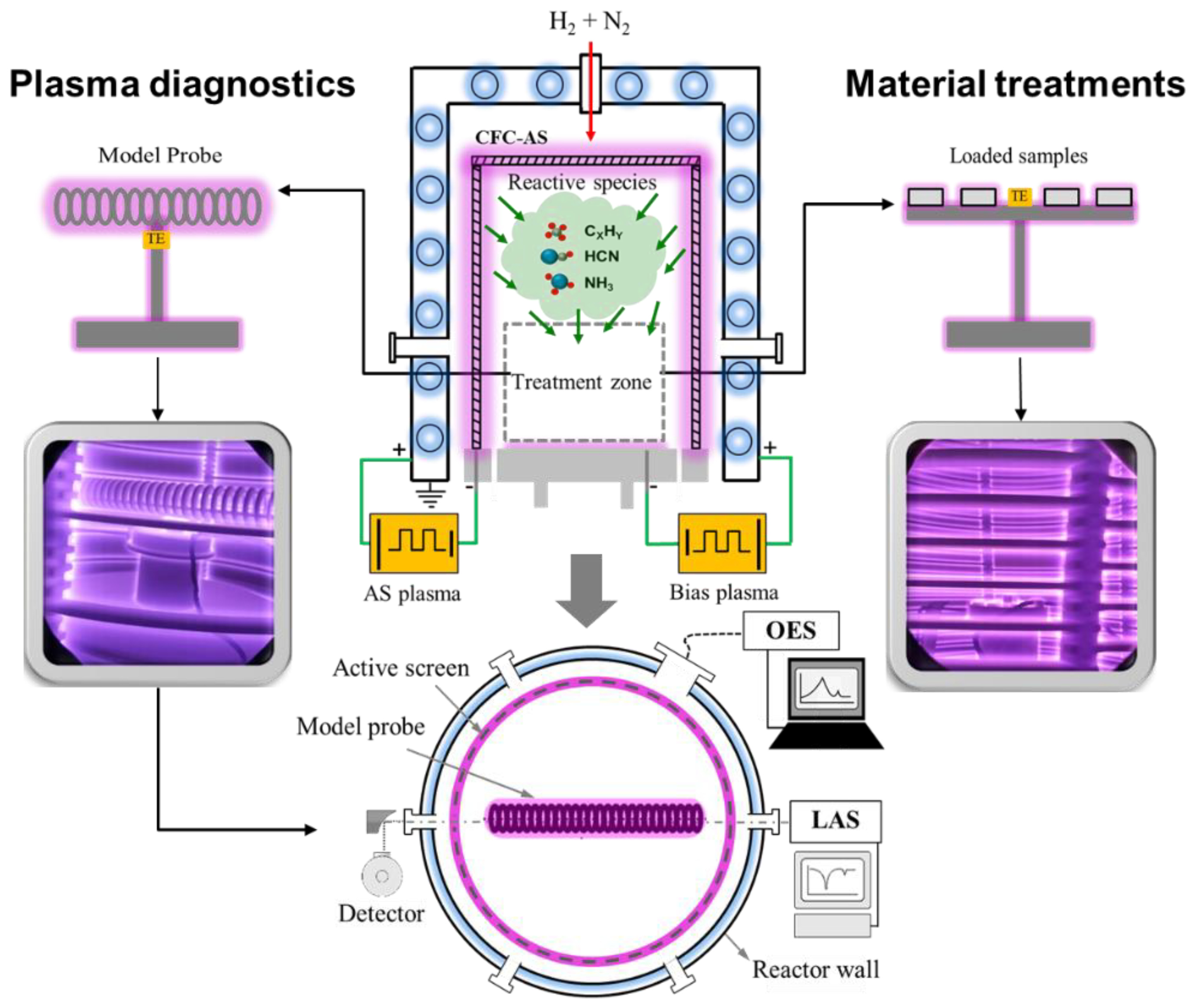
3.1. Behaviour of Cold-Wall Reactor during ASPNC

During the ASPNC treatments in the industrial-scale cold-wall reactor, the AS plasma power, current and voltage increased by decreasing the bias plasma power at a constant feed-gas composition and treatment temperature (Figure 2). A proportional–integral–derivative (PID) controller (K.S.L AUTOMATION SARL, Ettelbruck, Luxembourg) regulated the AS plasma power to achieve and stabilize the set treatment temperature, measured with thermocouples next to the workload. Accordingly, when a weak bias plasma power was applied at the components, the additional heating caused by the resulting bias plasma power led to the reduction in the AS plasma power to maintain the treatment temperature. This leads to a decrease in the rate of chemical sputtering of the CFC-AS by increasing the bias plasma power in case of treatments using a CFC-AS, which leads to lower concentrations of the carbon-containing gas species (Figure 2c). In addition, increasing the amount of N2 feed gas in the mixture at a constant bias plasma power led to a decrease in AS plasma power, voltage and current (Figure 2). Here, the AS plasma power was decreased with further admixture of the N2 feed gas to maintain a desired treatment temperature (Figure 2c). This may be attributed to the difference in the heat conductivity and density of H2 compared to N2 [25,26].

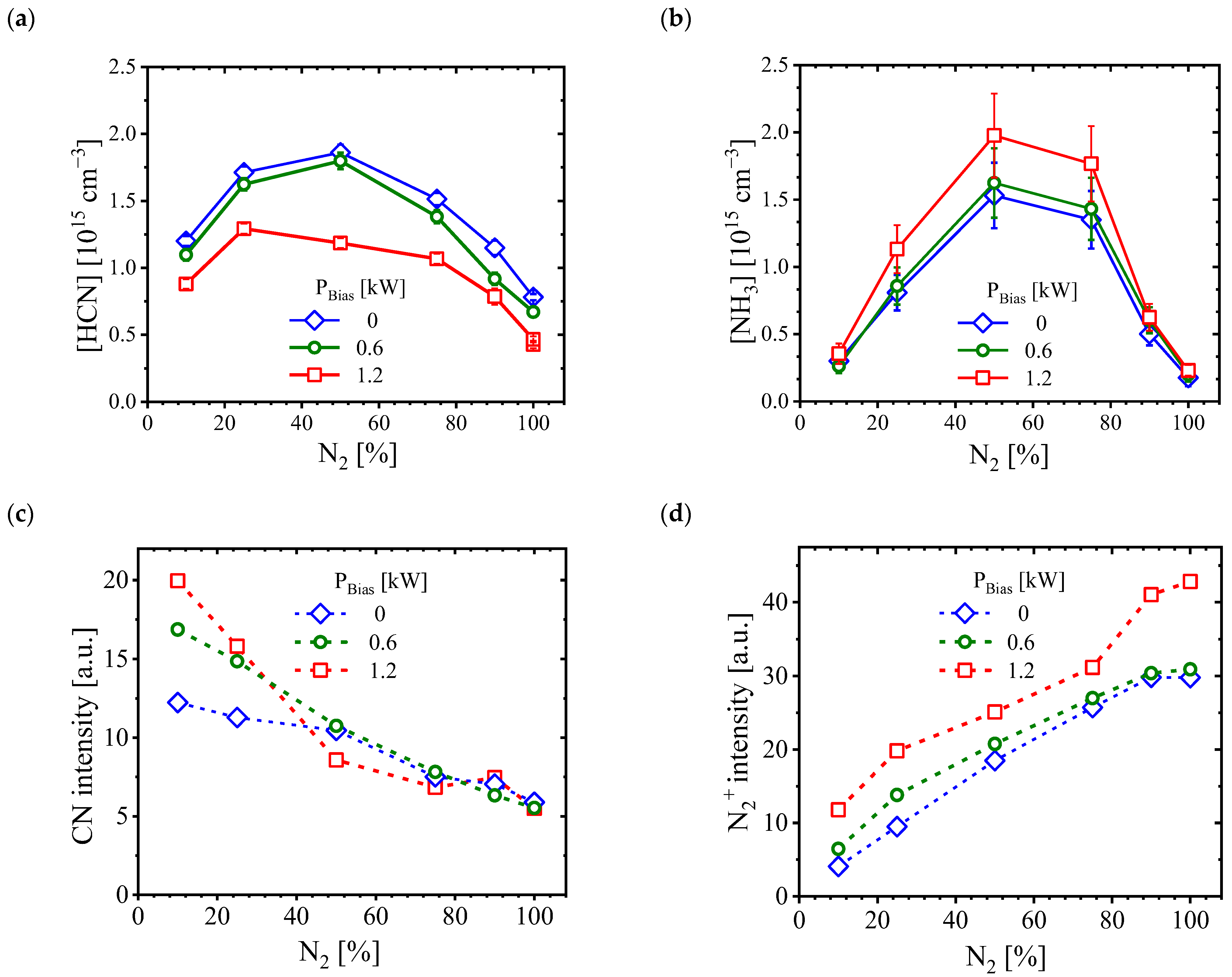
3.2. In Situ Plasma Diagnostics

During the ASPNC treatments with a CFC-AS, various saturated (CH4 and C2H6) and unsaturated hydrocarbons (C2H2 and C2H4), radicals (CH3), ammonia (NH3) and cyanides (HCN and C2N2) were formed. The absolute concentrations of the two most important process-relevant species HCN and NH3 were determined by utilizing LAS in situ at different bias conditions of 0, 0.6 and 1.2 kW as a function of the feed-gas composition (N2 in vol.%) (Figure 3a,b). The variation in feed-gas composition affected the concentrations of HCN and NH3 in such a way that the highest concentrations of both species were achieved at 50% N2 in all three cases of the applied bias conditions, whereas significantly lower concentrations of both species were gained at 10% and 90% N2. In addition, Figure 3a,b show that increasing the bias power from 0 to 1.2 kW led to a decrease in the HCN concentration and an increase in the NH3 concentration.
Figure 3c,d show the intensities of CN and N2+ measured in situ by utilizing OES, respectively. At the lowest N2 feed-gas composition, the highest signal intensity of CN was observed for all conditions. However, increasing the N2 feed-gas composition resulted in a decrease in the CN signal intensity (Figure 3c). In addition, the OES data showed that the application of the bias power enhanced the signal intensity of the N2+ ion near the surface of the model probe (Figure 3d). In addition, the admixture of more N2 led to an increase in the signal intensity of N2+ for all conditions. It is worth mentioning here that, in the case of nonbiased condition, the measured signal intensities of N2+ and CN were mainly from the negative glow that formed around the AS due to the lack of discharge plasma at the model probe. In this case, the dependence of the intensities of the species on the amount of N2 feed gas is governed by the variation in the AS plasma power due to the different N2 amounts.

3.3. Structural Properties of Expanded Austenite Layer

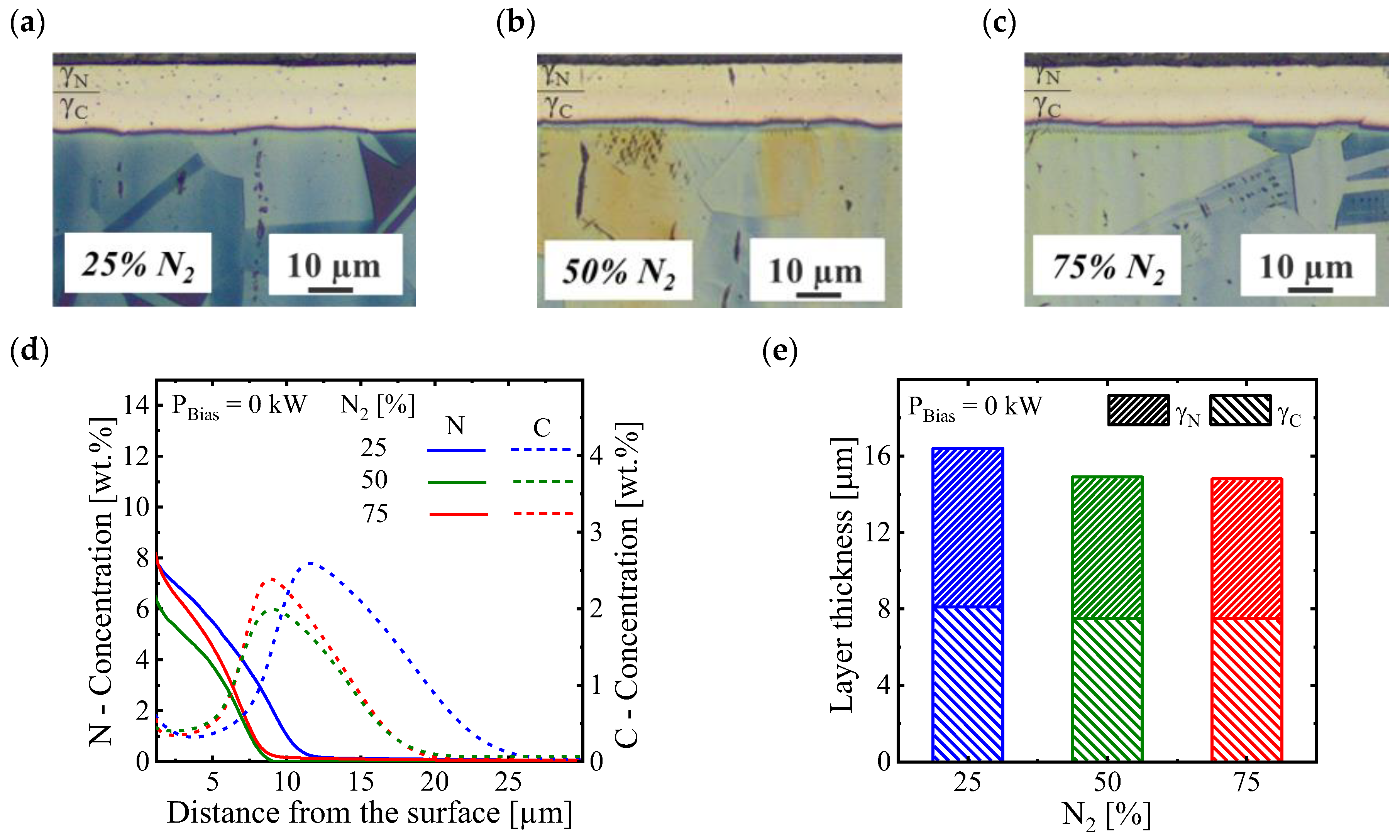
3.3.1. Effect of Gas Composition in a Nonbiased Condition

The cross-sectional optical micrographs of ASPNC AISI 316L samples treated at different feed-gas compositions under a nonbiased condition (PBias = 0 kW) are illustrated in Figure 4a–c. For all gas compositions investigated, a dual-layer structure consisting of a nitrogen-expanded austenite (γN) on top of a carbon-expanded austenite (γC) was formed (Figure 4a–c). The concentration–depth profiles of C and N in wt.%, measured with GDOES from the generated expanded austenite layers, are shown in Figure 4d. From the GDOES results, it can be concluded that for all feed-gas compositions investigated, the highest nitrogen content of about 6–8 wt.% was achieved near the surface (Figure 4d). In contrast, the maximum carbon content of up to 2–2.5 wt.% was introduced in the γC layer. The thicknesses of the expanded austenite layers generated in the case of a nonbiased condition are shown in Figure 4e. It was found that for ASPNC-treated samples, the thicknesses of γN and γC were roughly identical (γN ≅ γC) at each gas composition (Figure 4e). Furthermore, it was observed that the total thicknesses of expanded austenite layers (γNC) were approximately identical at about 15.8 µm.

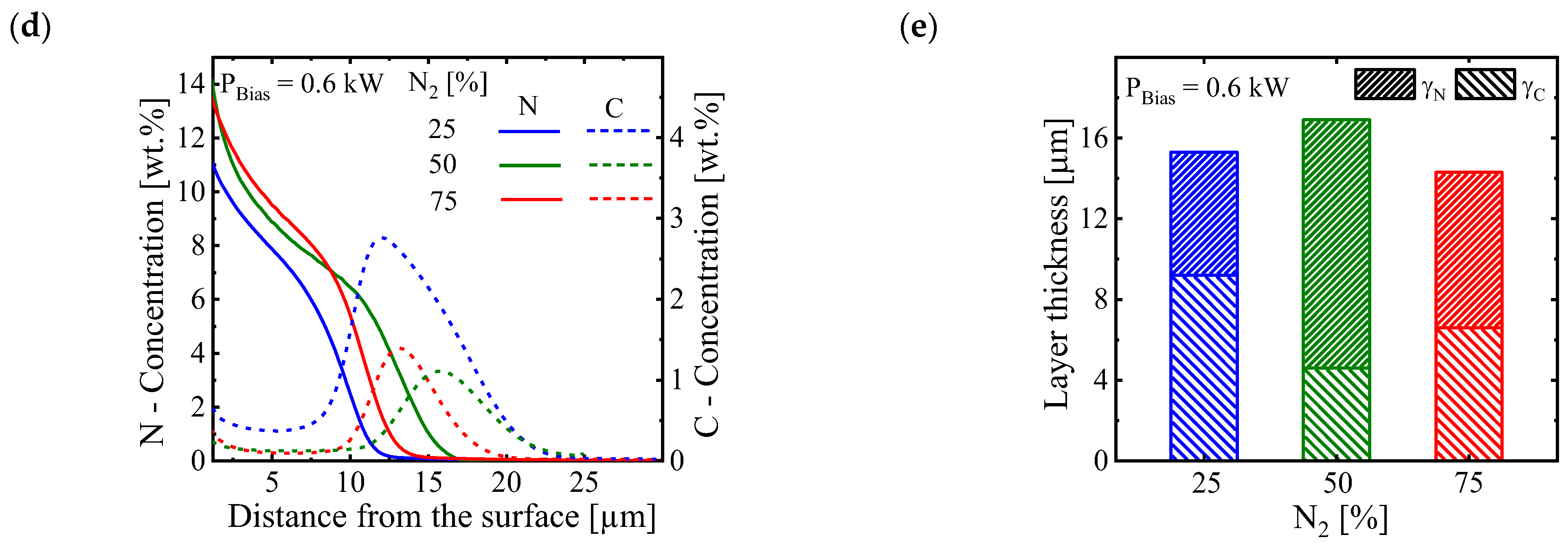
3.3.2. Effect of Gas Composition at 0.6 kW Biased Condition

The cross-sectional optical micrographs of ASPNC AISI 316L samples treated at different feed-gas compositions under a 0.6 kW biased condition applied at the treated samples are illustrated in Figure 5a–c. Similar to the nonbiased condition, it was found that for all investigated feed-gas compositions, a dual-layer structure consisting of a γN layer on top of a γC layer was formed (Figure 5a–c). The concentration–depth profiles of C and N in wt.% are shown in Figure 5d. From the GDOES results, it can be concluded that for all investigated treatment conditions, the highest nitrogen content was around 11–14 wt.% (Figure 5d). A maximum carbon content of up to 3 wt.% was introduced in the γC layer in the case of 25% N2, whereas a maximum carbon content of up to 1.3 wt.% was achieved in the other conditions. The thicknesses of the expanded austenite layers generated under 0.6 kW biased condition are shown in Figure 5e. It can be concluded that by increasing the N2 content, the total thickness of the generated expanded austenite layers (γNC) remained approximately the same at about 15.6 µm (Figure 5e). Furthermore, it was found that the thicknesses of γN and γC varied depending on the amount of N2 feed gas added (Figure 5e).

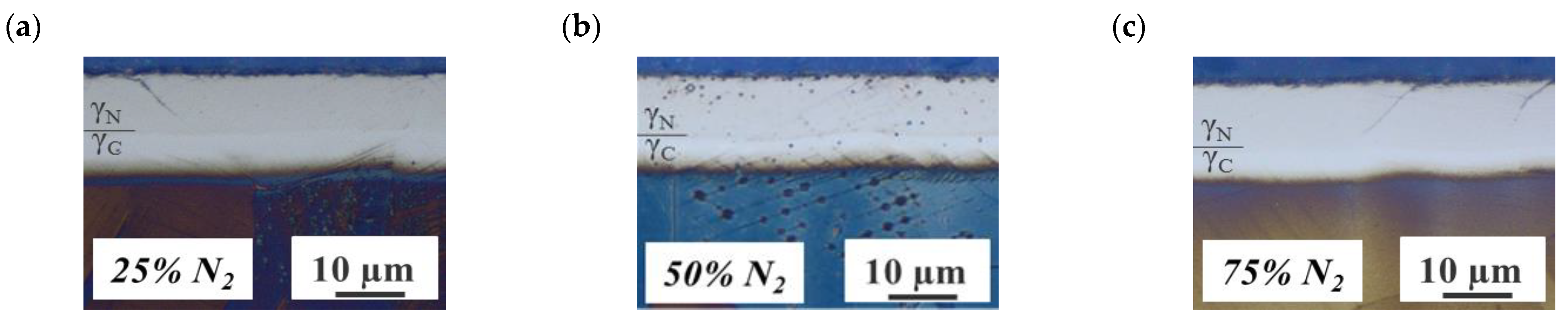
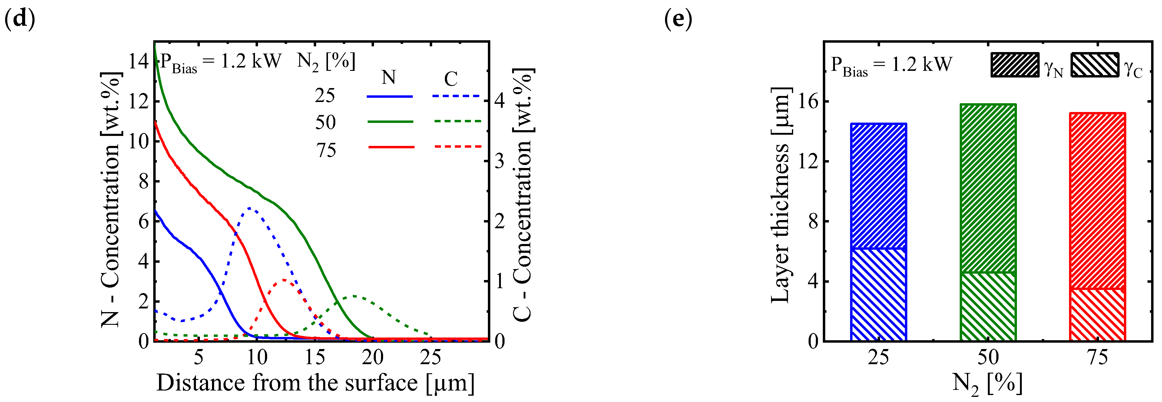
3.3.3. Effect of Gas Composition at 1.2 kW Biased Condition

The cross-sectional optical micrographs of ASPNC AISI 316L samples treated at different gas compositions under a 1.2 kW biased condition (PBias = 1.2 kW) are illustrated in Figure 6a–c. Again, in all gas compositions investigated, a dual-layer structure consisting of a γN layer on top of a γC layer was formed (Figure 6a–c). The concentration–depth profiles of C and N in wt.% are shown in Figure 6d. From the GDOES results, it can be concluded that in the case of 25% N2, the highest N content of about 6 wt.% was obtained, whereas for the other feed-gas compositions, the highest N content of about 11–14 wt.% was obtained (Figure 6d). Moreover, in the case of 25% N2, a maximum carbon content of up to 2 wt.% was introduced in the γC layer, whereas for the other gas compositions a maximum carbon content of up to 0.9–1.1 wt.% was introduced. The thicknesses of the expanded austenite layers generated under a 1.2 kW biased condition are shown in Figure 6e. It was revealed that by increasing the N2 feed-gas content, the total thickness of the generated expanded austenite layers remained approximately the same, at about 15.6 µm (Figure 6e). In addition, it was found that the thicknesses of γN and γC varied depending on the amount of N2 feed gas added (Figure 6e).

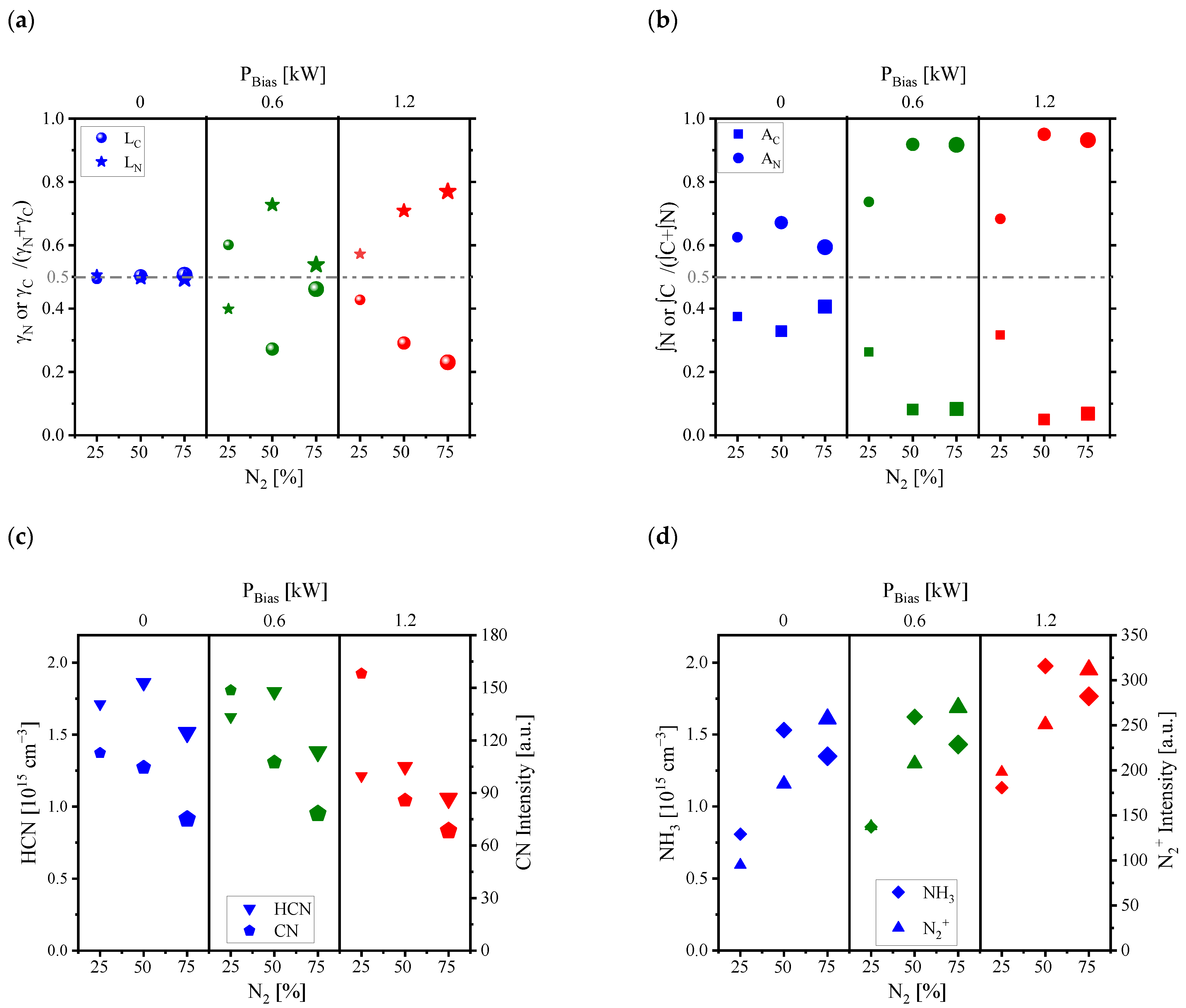
3.4. The Interplay Effects between Feed-Gas Compositions and Bias Conditions

In the current work, it is shown that the ability to change crucial treatment parameters, such as feed-gas composition and/or bias plasma conditions, in ASPNC treatments with a CFC-AS allows one to influence the concentrations/intensities of the generated reactive process-relevant species (such as CN, N2+, HCN and NH3) in the resulting treatment environment (Figure 3). This, in turn, allows one to control the surface properties of the generated C- and N-expanded austenite layers by tailoring the γN- and γC-layer thicknesses, as well as the contents of interstitial N and C diffused into the austenite (Figure 4, Figure 5 and Figure 6). In order to better clarify such correlations, the interplay effects between the feed-gas composition and the bias plasma condition in the ASPNC treatment with a CFC-AS and their influence on the structural properties of the generated expanded austenite layers, the characteristics of the generated modified layer can be evaluated based on two factors, namely, the thickness of the generated γN and γC layers (diffusion depth factor, LN,C) and the contents of interstitial N and C atoms inside the expanded austenite (concentration factor; AN,C):
LN or C = Layer thickness of γN or γC/Sum of the γN and γC layer thicknesses
AN or C = Integrated area over the concentration profile of N or C/Sum of the integrated areas over concentration profiles of N and C
The main objective is thus to find a correlation between (i) the treatment parameters (Figure 2) (gas composition and bias condition), (ii) the resulting treatment environment in terms of the type and concentrations/intensities of generated species (CN, N2+, HCN and NH3) (Figure 3) and (iii) the material response in terms of the two defined factors (LN, C and AN,C).
Table 2 gives the estimated values for the thickness of the γN and γC layers, as well as the integrated area over the N and C concentration–depth profiles (∫N and ∫C) extracted from the GDOES results of the treated samples in the different conditions investigated. From the data in Table 2, the diffusion depth factors (LN and LC) and the concentration factors (AN and AC) were determined, which are presented in Figure 7. The variations in the defined factors LC, LN, AC and AN (LN and AN correspond to the nitriding whereas LC and AC correspond to the carburizing effects at the treated samples) as a function of the N2 amount in the feed-gas composition and/or bias conditions are shown in Figure 7a,b, whereas the variations in the HCN, CN, N2+ and NH3 concentrations/intensities (corresponding to the reactivity of the generated treatment environment) as a function of the N2 amount in the feed-gas composition and/or biased conditions are shown in Figure 7c,d. Therefore, the correlation between concentrations/intensities of the generated process-relevant species (Figure 7c,d) in the treatment environment with the resulting nitriding and carburizing effects (Figure 7a,b) in the treated sample under a defined treatment condition can be extracted. As an example, from Figure 7b,d, it can be concluded that the N concentration factors (AN) followed a similar trend as the N2+ signal intensities, and to a lesser extent as the NH3 concentrations, by varying the N2 feed gas and/or bias conditions.

4. Discussion

The duplex-layer structure of expanded austenite generated with the nitrocarburizing treatment combines the advantages of both carburized and nitrided layers: a smooth case–core transition of hardness and residual stress and a high hardness in the outer zone to improve wear resistance. In addition, the combination of C and N expanded austenite layers results in a higher load-bearing capacity of the material. Moreover, the graded interstitial content in the duplex-layer structure of the expanded austenite is beneficial for the fatigue properties [46,47]. During ASPNC treatments, there are three driving forces governing the N diffusion (and thus the nitriding effect) into the austenite: (i) The negatively charged sample can attract positively charge ions such as N2+ more efficiently in the case of the biased condition than in the nonbiased condition. (ii) By increasing the level of bias plasma power at the workload, the amount of N2+ generated that contributes to the nitriding effect also increased (Figure 3d). (iii) As the content of N2 in the feed gas increased, the amount of N2+ increased. Consequently, there was more N2+ available for the nitriding effect (Figure 3d).
As mentioned before, in case of ASPNC treatments with a CFC-AS at nonbiased condition (PBias = 0), the main mechanism for surface de-passivation is governed by the reaction of the in situ generated CN compounds (such as HCN and CN) with the surface [45]. Here, due to the generation of these CN compounds with relatively high concentrations at different feed-gas compositions (Figure 3a,c), the passive layer at the surface was effectively de-passivated for all feed-gas compositions investigated. Moreover, such high concentrations of CN compounds provide sufficient amount of N and C at the surface that can diffuse into the de-passivated steel, and an identical total layer thickness of expanded austenite (γNC) of about 15.8 µm were obtained (Figure 4e) for all feed-gas compositions investigated. Therefore, it can be concluded that the surface activation and the total thickness of expanded austenite layer (γNC) generated in ASPNC treatments with a CFC-AS at a nonbiased condition were independent from the feed-gas composition (Figure 4).
It was shown that by increasing N2 in the feed-gas composition, the detected CN intensity near the sample surface slightly decreased under nonbiased condition (Figure 7c). This may be related to the slightly lower AS plasma power at the low N2 content (Figure 2c and Figure 3c). It is worth to mention here that the measured N2+ intensity at nonbiased condition is mainly attributed to the ionization of N2 due to the plasma at the AS. It should be noted that for treatments at nonbiased condition, the main mechanism for N and/or C uptake is the adsorption (physical or chemical) of gas molecules (in particular CN compounds) from the treatment environment at the surface of the treated samples. Therefore, the nitriding effect induced by attracting of N2+ ions at the surface are really minor due to the noncharged samples.
It was also shown that under this condition (PBias = 0), approximately identical diffusion depth factors for both N and C of 0.5 were estimated (LC = LN) for different amounts of N2 feed gas (Figure 7a). Therefore, the LC and LN at nonbiased condition are comparable and independent of the added amount of N2 feed gas (Figure 7a). However, the concentration factors for N and C are estimated to be about 0.6 and 0.4, respectively (Figure 7b), for different amounts of N2 feed gas. Therefore, it can be concluded that estimated values of AC and AN at nonbiased conditions are independent from the added amount of N2 feed gas and AC < AN. As a result, in case of treatments under nonbiased condition, more N diffused into the austenite than C, whereas comparable layer thicknesses were measured for both N and C.
In the two biased conditions (0.6 and 1.2 kW), both N2+ and CN compounds (HCN and CN) can effectively contribute to the nitriding and carburizing effects. At the low amount of N2 feed gas (25%), the detected CN intensity was higher than in the nonbiased condition (Figure 7c). Furthermore, in this condition, the detected N2+ intensity at the samples position (model probe) was relatively low due to the low amount of N2 in the feed-gas composition (Figure 7d). It can be proposed that for both biased conditions using 25% N2 feed gas, both nitriding and carburizing effects were still governed by the surface adsorption of CN compounds, whereas N2+ made a minor contribution to the nitriding effect. However, at a bias power of 0.6 kW, the diffusion depth factors were LC ≃ 0.6 and LN ≃ 0.4 whereas at a bias power of 1.2 kW, the diffusion depth factors were LC ≃ 0.4 and LN ≃ 0.6. This can be correlated to the higher N2+ intensity at the 1.2 kW bias power condition compared to the 0.6 kW condition, which increases the N2+ ion contribution. Furthermore, the concentration factors of AC ≃ 0.3 and AN ≃ 0.7 were estimated for both biased conditions using 25% N2 feed-gas admixture. As the N2 feed gas increased (to 50% and 75%), due to the presence of more N2 for ionization, the intensity of N2+ near the sample surface (model probe) enhanced and consequently there was more N2+ at the samples that could reach the sample surface and be effectively taken up by the negatively charged samples (Figure 7d). On the other hand, the intensity of CN, which is mainly responsible for the carburizing in this condition, decreased by increasing the N2 feed-gas admixture. As a result, a more dominant ion nitriding effect is expected by increasing the N2 feed-gas admixture rather than the surface adsorption of CN compounds. Furthermore, in case of both biased conditions (0.6 kW and 1.2 kW), the same trend for the N and C concentrations factors was observed when varying the feed-gas composition. For both biased conditions, a high N concentration factor of about 0.9 was estimated, whereas the C concentrations factor was estimated to be about 0.1 (Figure 7a). It can be suggested that the amount of C and N diffused into the austenite was independent of the level of bias plasma, if any was applied.

5. Conclusions

It was shown that the ability to adjust the crucial ASPNC treatment parameters, such as feed-gas composition and/or level of bias plasma power, offers a wide range of possibilities to influence the treatment environment in terms of the concentrations of the process-relevant species generated, and thus tailor the carbon and nitrogen diffusion profiles (depth and concentration) within the treated material. This, in turn, provides different options for the modification of the structural properties of the generated dual-layer structure of expanded austenite (γNC), which may have some potential applications. In addition, it was shown that despite the variation in the N2 feed gas, the bias plasma condition (biased or nonbiased) at the treated samples as well as its level strongly influenced the nitriding and carburizing effects. Therefore, the applicability and combination of both approaches for controlling the nitriding and carburizing effects in ASPNC treatment were successfully demonstrated. The nitriding effect, i.e., nitrogen diffusion depth and content within the expanded austenite, strongly increased when applying bias plasma under high-N2 fractions in the H2-N2 feed gas, whereas an increased carburizing effect, i.e., carbon diffusion depth and content, was achieved under nonbiased conditions and independent from the H2-N2 feed-gas composition. Such an adjustment is possible with the interplay effects between the composition of the feed gas and the bias conditions due to their effects on both the diffusion depths and the contents of imposed N and C.

Author Contributions

Conceptualization, S.M.J. and A.D.; methodology, S.M.J. and A.V.P.; formal analysis, A.V.P. and A.P.; investigation, S.M.J. and A.V.P.; writing—original draft preparation, S.M.J.; writing—review and editing, A.V.P., A.D., J.-P.H.v.H. and H.B.; visualization, S.M.J.; supervision, H.B., J.R. and J.-P.H.v.H.; project administration, A.D.; funding acquisition, H.B., A.D., J.R. and J.-P.H.v.H. All authors have read and agreed to the published version of the manuscript.

Funding

The authors appreciate the Federal Ministry of Education and Research (BMBF) for providing financial support in the framework of the validation funding VIP+ in the project PNC-Control (project numbers 03VP05501 and 03VP05502).

Institutional Review Board Statement

Not applicable.

Informed Consent Statement

Not applicable.

Data Availability Statement

Not applicable.

Conflicts of Interest

The authors declare no conflict of interest.

References

  1. Borgioli, F.; Galvanetto, E.; Bacci, T. Surface Modification of Austenitic Stainless Steel by Means of Low Pressure Glow-Discharge Treatments with Nitrogen. Coatings 2019, 9, 604. [Google Scholar] [CrossRef] [Green Version]
  2. Mingolo, N.; Tschiptschin, A.; Pinedo, C. On the formation of expanded austenite during plasma nitriding of an AISI 316L austenitic stainless steel. Surf. Coat. Technol. 2006, 201, 4215–4218. [Google Scholar] [CrossRef]
  3. Souza, R.; Ignat, M.; Pinedo, C.; Tschiptschin, A. Structure and properties of low temperature plasma carburized austenitic stainless steels. Surf. Coat. Technol. 2009, 204, 1102–1105. [Google Scholar] [CrossRef]
  4. Molleja, J.G.; Nosei, L.; Ferrón, J.; Bemporad, E.; Lesage, J.; Chicot, D.; Feugeas, J. Characterization of expanded austenite developed on AISI 316L stainless steel by plasma carburization. Surf. Coat. Technol. 2010, 204, 3750–3759. [Google Scholar] [CrossRef]
  5. Werner, K.V.; Che, H.L.; Lei, M.K.; Christiansen, T.L.; Somers, M.A.J. Low Temperature Carburizing of Stainless Steels and the Development of Carbon Expanded Austenite. HTM J. Heat Treat. Mater. 2022, 77, 3–15. [Google Scholar] [CrossRef]
  6. Chen, F.-S.; Chang, C.-N. Effect of CH4 addition on plasma nitrocarburizing of austenitic stainless steel. Surf. Coat. Technol. 2003, 173, 9–18. [Google Scholar] [CrossRef]
  7. Spies, H.-J.; Eckstein, C.; Biermann, H.; Franke, A. Corrosion behaviour of stainless steels after low temperature thermochemical treatment. Mater. Werkst. 2010, 41, 133–141. [Google Scholar] [CrossRef]
  8. Köster, K.; Kaestner, P.; Bräuer, G.; Hoche, H.; Troßmann, T.; Oechsner, M. Material condition tailored to plasma nitriding process for ensuring corrosion and wear resistance of austenitic stainless steel. Surf. Coat. Technol. 2013, 228, S615–S618. [Google Scholar] [CrossRef]
  9. Fossati, A.; Borgioli, F.; Galvanetto, E.; Bacci, T. Corrosion resistance properties of glow-discharge nitrided AISI 316L austenitic stainless steel in NaCl solutions. Corros. Sci. 2006, 48, 1513–1527. [Google Scholar] [CrossRef]
  10. Flis, J. Corrosion and passivation of plasma nitrided stainless steels. Surf. Eng. 2010, 26, 103–113. [Google Scholar] [CrossRef]
  11. Sun, Y.; Haruman, E. Low Temperature Plasma Surface Alloying of Austenitic Stainless Steels. Solid State Phenom. 2006, 118, 85–90. [Google Scholar] [CrossRef]
  12. Borgioli, F. From Austenitic Stainless Steel to Expanded Austenite-S Phase: Formation, Characteristics and Properties of an Elusive Metastable Phase. Metals 2020, 10, 187. [Google Scholar] [CrossRef] [Green Version]
  13. Sun, Y.; Haruman, E. Influence of processing conditions on structural characteristics of hybrid plasma surface alloyed austenitic stainless steel. Surf. Coat. Technol. 2008, 202, 4069–4075. [Google Scholar] [CrossRef]
  14. Sun, Y. Production of nitrogen and carbon S phases in austenitic stainless steels by hybrid plasma surface alloying. Surf. Eng. 2010, 26, 114–122. [Google Scholar] [CrossRef]
  15. Heras, E.D.L.; Ybarra, G.; Lamas, D.; Cabo, A.; Dalibon, E.L.; Brühl, S.P. Plasma nitriding of 316L stainless steel in two different N2-H2 atmospheres—Influence on microstructure and corrosion resistance. Surf. Coat. Technol. 2017, 313, 47–54. [Google Scholar] [CrossRef]
  16. Li, C.X.; Bell, T.; Dong, H. A Study of Active Screen Plasma Nitriding. Surf. Eng. 2002, 18, 174–181. [Google Scholar] [CrossRef]
  17. Spies, H.-J.; Burlacov, I.; Börner, K.; Biermann, H. IFHTSE Global 21: Heat treatment and surface engineering in the twenty-first century Active screen plasma nitriding and nitrocarburising of steels: An overview. Int. Heat Treat. Surf. Eng. 2014, 8, 94–106. [Google Scholar] [CrossRef]
  18. Georges, J. Nitriding Process and Nitriding Furnace Therefor. U.S. Patent 5,989,363, 23 November 1999. [Google Scholar]
  19. Li, C.X.; Georges, J.; Li, X. Active screen plasma nitriding of austenitic stainless steel. Surf. Eng. 2002, 18, 453–457. [Google Scholar] [CrossRef]
  20. Burlacov, I.; Hamann, S.; Spies, H.J.; Dalke, A.; Röpcke, J.; Biermann, H. A Novel Approach of Plasma Nitrocarburizing Using a Solid Carbon Active Screen—A Proof of Concept. HTM J. Heat Treat. Mater. 2017, 72, 254–259. [Google Scholar] [CrossRef]
  21. Dalke, A.; Burlacov, I.; Spies, H.-J.; Biermann, H. Use of a solid carbon precursor for DC plasma nitrocarburizing of AISI 4140 steel. Vacuum 2018, 149, 146–149. [Google Scholar] [CrossRef]
  22. Dalke, A.; Burlacov, I.; Hamann, S.; Puth, A.; Spies, H.-J.; Röpcke, J.; Biermann, H. Plasma Nitrocarburizing of AISI 316L Austenitic Stainless Steel Applying a Carbon Active Screen: Status and Perspectives. HTM J. Heat Treat. Mater. 2018, 73, 246–257. [Google Scholar] [CrossRef]
  23. Hopf, C.; Jacob, W. Bombardment of graphite with hydrogen isotopes: A model for the energy dependence of the chemical sputtering yield. J. Nucl. Mater. 2005, 342, 141–147. [Google Scholar] [CrossRef]
  24. Jacob, W.; Hopf, C.; Schlüter, M. Chemical sputtering of carbon by nitrogen ions. Appl. Phys. Lett. 2005, 86, 204103. [Google Scholar] [CrossRef]
  25. Jafarpour, S.M.; Puth, A.; Dalke, A.; Böcker, J.; Pipa, A.; Röpcke, J.; van Helden, J.-P.H.; Biermann, H. Solid carbon active screen plasma nitrocarburizing of AISI 316L stainless steel in cold wall reactor: Influence of plasma conditions. J. Mater. Res. Technol. 2020, 9, 9195–9205. [Google Scholar] [CrossRef]
  26. Böcker, J.; Puth, A.; Dalke, A.; Röpcke, J.; van Helden, J.-P.H.; Biermann, H. Influence of the Active Screen Plasma Power during Afterglow Nitrocarburizing on the Surface Modification of AISI 316L. Coatings 2020, 10, 1112. [Google Scholar] [CrossRef]
  27. Hamann, S.; Burlacov, I.; Spies, H.J.; Biermann, H.; Röpcke, J. Spectroscopic investigations of plasma nitriding processes: A comparative study using steel and carbon as active screen materials. J. Appl. Phys. 2017, 121, 153301. [Google Scholar] [CrossRef]
  28. Puth, A.D.F.; Kusýn, L.; Pipa, A.; Burlacov, I.; Dalke, A.; Hamann, S.; van Helden, J.-P.H.; Biermann, H.; Röpcke, J. Spectroscopic study of plasma nitrocarburizing processes with an industrial-scale carbon active screen. Plasma Sources Sci. Technol. 2020, 29, 035001. [Google Scholar] [CrossRef]
  29. Jafarpour, S.M.; Pipa, A.V.; Puth, A.; Dalke, A.; Röpcke, J.; van Helden, J.-P.H.; Biermann, H. Effects of Plasma-Chemical Composition on AISI 316L Surface Modification by Active Screen Nitrocarburizing Using Gaseous and Solid Carbon Precursors. Metals 2021, 11, 1411. [Google Scholar] [CrossRef]
  30. Jafarpour, S.; Dalke, A.; Biermann, H. Plasma Nitrocarburizing of AISI 316L Austenitic Stainless Steel: A First Step for Treatment of Components with Complex Geometries. HTM J. Heat Treat. Mater. 2020, 75, 95–112. [Google Scholar] [CrossRef]
  31. Dalke, A.; Burlacov, I.; Hamann, S.; Puth, A.; Böcker, J.; Spies, H.-J.; Röpcke, J.; Biermann, H. Solid carbon active screen plasma nitrocarburizing of AISI 316L stainless steel: Influence of N2-H2 gas composition on structure and properties of expanded austenite. Surf. Coat. Technol. 2019, 357, 1060–1068. [Google Scholar] [CrossRef]
  32. Pipa, A.V.; Puth, A.; Böcker, J.; Jafarpour, S.; Dalke, A.; Biermann, H.; Röpcke, J.; van Helden, J.H. Laser absorption spectroscopy for plasma-assisted thermochemical treatment I: Applicability of Beer-Lambert law and interpretation of spectroscopic data. Plasma Sources Sci. Technol. 2023; in press. [Google Scholar]
  33. Maki, A.; Mellau, G.; Klee, S.; Winnewisser, M.; Quapp, W. High-Temperature Infrared Measurements in the Region of the Bending Fundamental of H12C14N, H12C15N, and H13C14N. J. Mol. Spectrosc. 2000, 202, 67–82. [Google Scholar] [CrossRef] [Green Version]
  34. Maki, A.; Quapp, W.; Klee, S. Intensities of Hot-Band Transitions: HCN Hot Bands. J. Mol. Spectrosc. 1995, 171, 420–434. [Google Scholar] [CrossRef]
  35. Barber, R.J.; Strange, J.K.; Hill, C.; Polyansky, O.L.; Mellau, G.C.; Yurchenko, S.N.; Tennyson, J. ExoMol line lists—III. An improved hot rotation-vibration line list for HCN and HNC. Mon. Not. R. Astron. Soc. 2014, 437, 1828–1835. [Google Scholar] [CrossRef] [Green Version]
  36. Harris, G.J.; Tennyson, J.; Kaminsky, B.M.; Pavlenko, Y.V.; Jones, H.R.A. Improved HCN/HNC linelist, model atmospheres and synthetic spectra for WZ Cas. Mon. Not. R. Astron. Soc. 2006, 367, 400–406. [Google Scholar] [CrossRef] [Green Version]
  37. Makhnev, V.Y.; Kyuberis, A.A.; Polyansky, O.L.; Mizus, I.I.; Tennyson, J.; Zobov, N.F. A new spectroscopically-determined potential energy surface and ab initio dipole moment surface for high accuracy HCN intensity calculations. J. Mol. Spectrosc. 2018, 353, 40–53. [Google Scholar] [CrossRef] [Green Version]
  38. Cottaz, C.; Kleiner, I.; Tarrago, G.; Brown, L.R.; Margolis, J.S.; Poynter, R.L.; Pickett, H.M.; Fouchet, T.; Drossart, P.; Lellouch, E. Line Positions and Intensities in the 2ν2ν4 Vibrational System of 14NH3 near 5–7 µm. J. Mol. Spectrosc. 2000, 203, 285–309. [Google Scholar] [CrossRef]
  39. Down, M.J.; Hill, C.; Yurchenko, S.N.; Tennyson, J.; Brown, L.R.; Kleiner, I. Re-analysis of ammonia spectra: Updating the HITRAN 14NH3 database. J. Quant. Spectrosc. Radiat. Transf. 2013, 130, 260–272. [Google Scholar] [CrossRef] [Green Version]
  40. Yurchenko, S.N. A theoretical room-temperature line list for 15NH3. J. Quant. Spectrosc. Radiat. Transf. 2015, 152, 28–36. [Google Scholar] [CrossRef] [Green Version]
  41. Canè, E.; Di Lonardo, G.; Fusina, L.; Tamassia, F.; Predoi-Cross, A. Spectroscopic characterization of the ν2 = 3 and ν2 = ν4 = 1 states for 15NH3 from high resolution infrared spectra. J. Quant. Spectrosc. Radiat. Transf. 2020, 250, 106987. [Google Scholar] [CrossRef]
  42. Canè, E.; Di Lonardo, G.; Fusina, L.; Tamassia, F.; Predoi-Cross, A. The ν2 = 1, 2 and ν4 = 1 bending states of 15NH3 and their analysis at experimental accuracy. J. Chem. Phys. 2019, 150, 194301. [Google Scholar] [CrossRef] [PubMed]
  43. Gordon, I.E.; Rothman, L.S.; Hargreaves, R.J.; Hashemi, R.; Karlovets, E.V.; Skinner, F.M.; Conway, E.K.; Hill, C.; Kochanov, R.V.; Tan, Y.; et al. The HITRAN2020 molecular spectroscopic database. J. Quant. Spectrosc. Radiat. Transf. 2022, 277, 107949. [Google Scholar] [CrossRef]
  44. Baranowska, J. Importance of surface activation for nitrided layer formation on austenitic stainless steel. Surf. Eng. 2010, 26, 293–298. [Google Scholar] [CrossRef]
  45. Hoshino, K.; Miyashita, M.; Kawamura, T.; Totsuka, T.; Eiraku, H.; Yashiro, K.; Kurosawa, T. Method for Activating Surface of Metal Member. EP 1707646 A1, 4 October 2006. [Google Scholar]
  46. Czerwiec, T.; He, H.; Marcos, G.; Thiriet, T.; Weber, S.; Michel, H. Fundamental and Innovations in Plasma Assisted Diffusion of Nitrogen and Carbon in Austenitic Stainless Steels and Related Alloys. Plasma Process. Polym. 2009, 6, 401–409. [Google Scholar] [CrossRef]
  47. Nascimento, F.C.; Lepienski, C.M.; Foerster, C.E.; Assmann, A.; da Silva, S.L.R.; Siqueira, C.J.d.M.; Chinelatto, A.L. Structural, mechanical, and tribological properties of AISI 304 and AISI 316L steels submitted to nitrogen–carbon glow discharge. J. Mater. Sci. 2009, 44, 1045–1053. [Google Scholar] [CrossRef]
Figure 1. Schematic diagram of the industrial-scale cold-wall ASPNC reactor with a CFC-AS (centre), illustrating the plasma diagnostics (left and bottom) and material treatment (right) setups (Adapted from Ref. [29]).
Coatings 13 01103 g001
Figure 2. Variation in CFC-AS current (a), voltage (b) and power (c) as a function of feed-gas composition (N2 in vol.%) under different bias conditions (PBias = 0, 0.6, 1.2 kW) using p = 3 mbar, T = 460 °C and ΦTotal = 80 slh treatment parameters.
Coatings 13 01103 g002
Figure 3. LAS and OES data recorded during ASPNC with a CFC-AS under different bias conditions and feed-gas compositions. (a) Concentration of HCN, (b) concentration of NH3, (c) signal intensity of CN and (d) signal intensity of N2+ using p = 3 mbar, T = 460 °C and ΦTotal = 80 slh treatment parameters.
Coatings 13 01103 g003
Figure 4. Cross-sectional optical light microscopy images (ac), concentration–depth profiles (d) and layer thicknesses (e) of ASPNC AISI 316L samples treated in a nonbiased condition (PBias = 0 kW), under variation in the feed-gas composition at p = 3 mbar, T = 460 °C, ΦTotal = 80 slh and t = 5 h as treatment parameters. In sub-figures (a,b) and (e), γN indicates the N-expanded austenite layer and γC indicates the C-expanded austenite layer.
Coatings 13 01103 g004
Figure 5. Cross-sectional optical light microscopy images (ac), concentration–depth profiles (d) and expanded austenite layer thicknesses (e) of ASPNC AISI 316L samples treated in a 0.6 kW biased condition (PBias = 0.6 kW) under variation in the feed-gas composition using p = 3 mbar, T = 460 °C, ΦTotal = 80 slh and t = 5 h treatment parameters.
Coatings 13 01103 g005aCoatings 13 01103 g005b
Figure 6. Cross-sectional optical light microscopy images (ac) as well as concentration–depth profiles (d) and expanded austenite layer thicknesses (e) of ASPNC AISI 316L samples treated in a 1.2 kW biased condition (PBias = 1.2 kW) under variation in the feed-gas composition using p = 3 mbar, T = 460 °C, ΦTotal = 80 slh and t = 5 h treatment parameters.
Coatings 13 01103 g006aCoatings 13 01103 g006b
Figure 7. Diffusion depth factors, LN or C (a) and concentration factors, AN or C (b) for N and C extracted from generated expanded austenite layers of ASPNC AISI 316L samples treated in different feed-gas compositions under the variation in bias plasma power. Concentrations of HCN and NH3 evaluated from in situ LAS measurements, as well as the intensities of signals of detected CN and N2+ measured with OES for comparable treatments (c,d). The error bar for the concentration factor was around 8%, whereas the error bar for diffusion depth factor was around 10%. The size of the symbols increases with increasing level of N2 feed-gas admixture. Blue color refers to PBias = 0 kW, green color refers to PBias = 0.6 kW and red color refers to PBias = 1.2 kW.
Coatings 13 01103 g007
Table 1. Molecules monitored with LAS and relevant spectral line data: wavenumbers (ν), temperature determined from the Doppler broadening of the line (Teff), corresponding line strength S(Teff) and references from which spectroscopic-relevant molecular properties have been taken.
Moleculeν, cm−1Teff, KS(Teff), cmReferences
HCN1356.708777725 ± 757.415 × 10⁻²¹[37,38,39,40,41]
NH31388.05517725 ± 757.365 × 10⁻²¹[42,43,44,45,46]
Table 2. Measured values for the thicknesses of the γN and γC layers and the integrated area over N (∫N) and C (∫C) inside the expanded austenite layers prepared at different feed-gas compositions under the variation in the bias plasma power.
PBias
[kW]
25% N250% N275% N2
∫NγN∫CγC∫NγN∫CγC∫NγN∫CγC
046.98.1 µm28.18.3 µm37.67.4 µm19.27.5 µm28.87.3 µm18.97.5 µm
0.668.76.1 µm24.59.2 µm100.512.3 µm8.94.6 µm92.97.7 µm8.46.6 µm
1.232.368.3 µm156.2 µm12711.2 µm6.64.6 µm7011.7 µm5.13.5 µm
Disclaimer/Publisher’s Note: The statements, opinions and data contained in all publications are solely those of the individual author(s) and contributor(s) and not of MDPI and/or the editor(s). MDPI and/or the editor(s) disclaim responsibility for any injury to people or property resulting from any ideas, methods, instructions or products referred to in the content.

