Article

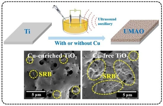
Ultrasound-Auxiliary Preparation of Antifouling Cu-Enriched Titanium Oxide Ceramic Layer

1
Key Laboratory of Material Chemistry for Energy Conversion and Storage, Ministry of Education, Hubei Key Laboratory of Material Chemistry and Service Failure, School of Chemistry and Chemical Engineering, Huazhong University of Science and Technology, 1037 Luoyu Road, Hongshan District, Wuhan 430074, China
2
School of Optical and Electronic Information, Huazhong University of Science and Technology, Wuhan 430074, China
*
Authors to whom correspondence should be addressed.
These authors contributed equally to this work.
Coatings 2023, 13(6), 1099; https://doi.org/10.3390/coatings13061099
Submission received: 11 May 2023 / Revised: 9 June 2023 / Accepted: 12 June 2023 / Published: 14 June 2023
(This article belongs to the Special Issue Wear, Friction and Corrosion of New Alloys (Bulk and Coatings))

Abstract

:
The limited antifouling capability of Ti-based components could jeopardize their applications in petroleum engineering. In this work, a Cu-enriched TiO2 coating has been fabricated using an ultrasound-auxiliary micro-arc oxidation (UMAO) method. The Cu enrichment of TiO2 affects its morphology, phase component and chemical configuration, leading to the slightly enhanced corrosion resistance of the Cu-enriched TiO2 coating relative to that free of Cu. Finally, the antifouling capability against sulphate-reducing bacteria (SRB) is significantly improved by preventing the formation of biofilm after the Cu enrichment of TiO2, which potentially widens its application in petroleum engineering.

Graphical Abstract

1. Introduction

Characterized by excellent corrosion resistance, high specific strength and high fatigue tolerance, Ti and its alloys are promising materials for petroleum engineering [1]. After years of technical investigations and estimations, commercially available Ti-based components that meet the requirements of mechanical strength and corrosion resistance for hydrocarbon well components in the petroleum industry have already been developed by the company RMI Titanium [2,3,4].
However, metallic components are inevitably exposed to a wide range of microbes during service in petroleum engineering, which may cause microbiologically influenced corrosion (MIC) considering the increasingly harsh environment of the petroleum industry [5,6,7]. To prevent the negative influence of MIC on these metallic components, it is necessary to increase their antifouling capabilities against microbes [8,9,10,11,12].
Sulphate-reducing bacteria (SRB), which have been widely used in the oil production system, may cause MIC, which is responsible for many industrial failures [6,7,13]. SRB tend to grow in anaerobic niches. After the initial adhesion, the extracellular polymeric substance (EPS) produced by SRB could gradually lead to the formation of a biofilm, which provides a suitable environment for the rapid proliferation of SRB and finally results in irreversible bio-fouling associated with SRB. The formation of SRB biofilm may give rise to serious MIC due to the following reasons. First, SRB in biofilm reduces sulphate to hydrogen sulphide (H2S), which thus acidifies the chemical environment to increase the corrosion susceptibility of the metallic substrate [6]. Second, the EPS produced by SRB biofilm accelerates the corrosion of the metallic substrate due to its high capability to bind with metal ions [14]. More importantly, hydrogenase from SRB biofilm could dramatically increase the cathodic hydrogen evolution reaction, which accelerates the corresponding anodic dissolution of the metallic substrate [6,15,16].
Even though Ti and its alloys generally display excellent corrosion resistance, it has been reported that the presence of a reducing environment of SRB culture could promote the breakdown of TiO2 film, which promotes the pitting corrosion of Ti via the formation of titanium sulphide [17]. For the petroleum industry, pitting corrosion could be dangerous, and may act as the nucleation for cracking and perforation with prolonged service periods and thereby give rise to catastrophic results. Therefore, it is necessary to endow Ti with antifouling capability against SRB.
Cu, as an effective antimicrobial agent [18,19,20], could offer a desirable antimicrobial capacity that impedes bacteria growth and thereby prevents the formation of biofilms. Nowadays, after the banning of tin-containing antifouling paints [21], antifouling coatings are mainly formulated with Cu-based compounds [8,9,10,11,22,23]. Hence, the fabrication of Cu-enriched coating on a Ti substrate could be promising in terms of enhancing its antifouling performance.
One of the most effective methods to produce Cu-enriched coating on a Ti substrate is micro-arc oxidation (MAO) [24,25]. As a typical valve metal, TiO2-based ceramic coating could grow in situ on the Ti substrate with the incorporation of Cu by simply adding Cu species as the electrolytic components [18,25,26,27,28]. In addition, the resulting ceramic coating produced through the MAO method exhibits a high chemical inertness, which means it could act as a physical barrier to improve the corrosion resistance of the Ti substrate [29,30,31]. Meanwhile, the high hardness of the ceramic coating also improves the wear resistance of the Ti substrate [32,33]. However, even with the successful incorporation of Cu into TiO2, the incorporation efficacy of Cu via the MAO method is generally low [27,28,34,35], therefore necessitating the addition of a large amount of Cu-containing electrolytic components for the fabrication of a Cu-enriched ceramic coating with the desired antifouling performance.
Two potential methods have been proposed to increase the incorporation efficacy. First, relative to conventional Cu sources such as Cu salts and Cu-containing nanoparticles, by using negatively charged Cu sources, such as Cu-EDTA complexes [18,19,26], the electro-migration process benefits the mass transport of Cu species to the anode, which increases the incorporation efficacy. In addition, the introduction of ultrasonic vibration (UV) as an assistant technology for the MAO process has also received wide attention [24,36,37]. The introduction of UV into MAO promotes the growth of ceramic oxide through the circulation of forming and healing of UV-induced defects. During the process, a micro-arc discharge event benefits the enrichment of electrolytic components [25]. The unique characteristics of UV, such as its cavitation effect, thermal effect, turbulent effect and perturbation effect, etc., could also promote the formation of the ceramic coating and enhance the coating performances if properly applied [25,38].
Hence, in the present work, the ultrasound-auxiliary micro-arc oxidation (UMAO) method was applied to fabricate a Cu-enriched TiO2 coating on a Ti substrate with Na2Cu-EDTA as the Cu source, and the influence of Cu enrichment on the microstructural features of TiO2 is discussed in detail. Furthermore, both the anti-corrosion property and antifouling capability of the Cu-enriched TiO2 coating were examined under a simulated petroleum industrial condition characterized by a corrosive chemical condition and the presence of SRB. The results in the present work indicate that UMAO is a promising method to effectively incorporate Cu into TiO2.

2. Experimental Methods

2.1. Preparation of Specimens

In this work, Ti substrates with a diameter of 20 mm were obtained by wire electrical discharge machining (WEDM) a TA2 rod. All samples were mechanically polished to 1200 grit, then were rinsed with de-ionized water and finally dried in a cool air stream.
Ultrasound-auxiliary micro-arc oxidation (UMAO) was conducted on these Ti samples using the set-up reported previously [38], with the ultrasonic frequency at 60 kHz and power at 50 W. During the UMAO process, a galvanostatic mode with the current density fixed at 80 mA/cm2 for 10 min was employed, and the oxidation time was 10 min. The basic electrolyte contained 15.8 g/L calcium acetate and 7.2 g/L sodium dihydrogen phosphate, and was used to produce Cu-free TiO2 coating. For comparison, 8 g/L Na2Cu-EDTA was added into the basic electrolyte for the production of Cu-enriched TiO2 coating. The specimens were thoroughly cleaned with deionized water before being dried in a cool air stream.

2.2. Microstructural and Property Characterization

All characterization processes are presented in the Supplementary Materials.

3. Results

Figure 1 shows the evolutions of the applied voltage with the oxidation period during the UMAO process. Both curves exhibit similar tendency: the applied voltage initially increases in a linear way, then increases more slowly and finally remains stabilized with slight fluctuations. Close examination reveals that after the addition of Na2Cu-EDTA into the electrolyte (with the concentration of 8 g/L), the breakdown potential of the UMAO process decreases clearly from ~298 V to ~284 V, which may be associated with Cu incorporation into the TiO2. By contrast, the stabilized potential (~474 V) is insensitive to the existence of Na2Cu-EDTA in the electrolyte. Hence, during the UMAO process, it seems that Cu-EDTA complexes mainly affect the breakdown of passive oxide rather than the electric resistance of the resulting coating, which directly affects the stabilized potential.
SEM examination was conducted to examine the surface appearances of both coatings (Figure 2). From the general views (Figure 2a,b), both coatings exhibit the porous structure typical for micro-arc oxidation [39]. The detailed morphological features of the framed areas in Figure 2a,b are shown in the panels in Figure 2c,d, which clearly reveal the presence of micro-sized pores (marked by red arrows) originating from micro-arc discharges. The porosity, which reflects the area percentage of micro-sized pores on the entire surface area, could be obtained based on the standard threshold segmentation method. The corresponding binary images of Figure 2c,d are shown in Figure S1a with the statistics result shown in Figure S1b, revealing that the porosity of the Cu-enriched coating (~4.92%) is lower than that of the Cu-free coating (~6.01%), which also performed better in related studies, as listed in Table S1. Finally, representative magnified views of both coatings are shown in Figure 2e,f. Narrow dark lines (marked by red arrows) can be noticed in both coatings, which belong to cracks associated with thermal stress during the UMAO process. Scrutiny of Figure 2e,f also reveals the presence of nano-sized pores that originate from oxygen generation [25].
EPMA analysis was conducted to evaluate the chemical compositions of both TiO2 coatings with the quantified chemical compositions presented in Table 1. Clearly, electrolytic components were successfully incorporated into TiO2 after the UMAO process, with the presence of both Ca and P in the Cu-free layer. Furthermore, Cu (~2.54 wt.%) was detected in the Cu-enriched TiO2 coating, indicating that Na2Cu-EDTA could act as a suitable Cu source for incorporating Cu into TiO2. The elemental distributions of Ca, P and Cu are relatively uniform across both coatings, which again confirms the incorporation of electrolytic components into TiO2 (Figure 3).
Afterwards, cross sections of both coatings were examined (Figure 4). As shown in Figure 4a,c, micrometre-scale bands were noticed between the epoxy layers and the underlying metallic substrates, which are micro-arc oxidized coatings. The framed areas of Figure 4a,c are magnified in Figure 4b,d, exhibiting obvious local variations in the coating thickness. The Cu-enriched TiO2 coating exhibits a thickness ranging from ~7.2 to 14 μm, which is similar to that of the Cu-free coating (~5.8 to 14.5 μm). Close examination of Figure 4b,d reveals their bi-layered structure. The outer layer is highly porous, comprising micron-sized pores, whereas the inner layer is relatively compact and may contain ultrafine nanometre-scale pores that originate from oxygen evolution [25].
The elemental profiles along both cross sections wee then examined using EPMA analysis (Figure 5), which again reveals the incorporation of electrolytic components into the TiO2. Interestingly, unlike the coating surface (Figure 3), the Ca and P distributions are uneven in the cross sections of both coatings. Scrutiny of Figure 5 reveals that the penetration depth of P is greater than Ca, which may be associated with their different charging conditions. P tends to exist as negatively charged anion, with its mass transfer promoted by the external electric field, whereas the external electric field decelerates the mass transfer of Ca, as a positively charged cation, into the coating. Cu was again detected in the Cu-enriched coating. Cu is distributed uniformly across the coating, which may be ascribed to the application of ultrasound during the MAO process.
To identify the phase components of both coatings, thin-film XRD (TFXRD) analysis was carried out, with representative patterns shown in Figure 6. As shown in Figure 6, both rutile and anatase were clearly observed in the coatings, with significant variations in the anatase to rutile ratio. The anatase to rutile ratio of the Cu-enriched TiO2 coating (~4.39) is much higher than that without Cu (~1.31), which will be illustrated later. In addition, the characteristic peaks of Ti could also be detected, which is ascribed to the limited thickness of the TiO2 (Figure 4) relative to the penetration depth of the X-rays.
Following the microstructural characterization, the surface conditions of both coatings were examined. Surface hydrophobicity was evaluated by measuring the water contact angle (WCA) (Figure 7a), whereas surface roughness was examined using surface topography (Figure 7b). The Cu-enriched coating exhibits a similar WCA and surface roughness compared to that without Cu, which indicates that the surface conditions of TiO2 produced through UMAO remain insensitive to Cu incorporation.
To assess the corrosion resistances of both coatings, the electrochemical responses were recorded. For comparison, electrochemical measurements of bare Ti substrate were also conducted.
The polarization curves of both coatings are presented in Figure 8, with bare Ti as a comparison. Based on Figure 8, the ennoblement of corrosion potential (Ecorr) after the UMAO process is obvious, which also occurs with Cu enrichment of TiO2. As presented in Table 2, the Cu-enriched TiO2 coating exhibits the largest βa, indicating that the electrochemical process is significantly inhibited. In addition, Ecorr follows the decreasing order (Figure S2a) Cu-enriched coating (~0.203 V) > Cu-free coating (~0.084 V) > bare Ti (~−0.26 V). Meanwhile, a reduction in corrosion current density (icorr) is also revealed after the formation of TiO2 and the incorporation of Cu, and follows the decreasing order (Figure S2a) Cu-enriched coating (4.96 × 10⁻⁹ A/cm2) < Cu-free coating (1.51 × 10⁻⁸ A/cm2) < bare Ti (7.93 × 10⁻⁷ A/cm2). Since icorr reflects the anti-corrosion performance of the specimen, the sequence preliminarily indicates that the application of UMAO and the incorporation of Cu are beneficial for the corrosion resistance of Ti.
Electrochemical impedance spectroscopy (EIS) analysis was also conducted on both Cu-enriched and Cu-free coatings, with bare Ti as a comparison. Both Nyquist and Bode plots of EIS are shown in Figure 9a,b. According to the Bode plots (Figure 9b), the impedance modulus (|Z|) at 10 mHz follows the decreasing order Cu-enriched coating > Cu-free coating > bare Ti. Since the |Z|10 mHz reflects the corrosion resistance, it is thus indicated that the Cu-enriched coating has enhanced corrosion resistance relative to the Cu-free coating and bare Ti. From the phase angle in the Bode plots (Figure 9b), it can be seen that bare Ti exhibits two time constants in the intermediate frequency and low frequency regions, corresponding to the solution/passivation film interface and the passivation film/substrate interface, respectively. Both the Cu-enriched TiO2 and Cu-free TiO2 exhibit two time constants in the low and high frequency regions, corresponding to the solution/TiO2 interface and the TiO2/substrate interface, respectively. Based on this, the equivalent circuit (EC) model of Figure 9c was applied to fit the EIS data with details reported previously [40]. The corresponding fitting results are listed in Table 3. The porous structure of both the Cu-enriched TiO2 and Cu-free TiO2 resulted in a higher CPEcoating-Q value, and the greater surface roughness also resulted in a slightly lower CPEcoating-n value. The sum of resistances again indicates that corrosion resistance follows the decreasing order (Figure S2b) Cu-enriched coating > Cu-free coating > bare Ti. Hence, the Cu-enriched coating exhibits enhanced corrosion resistance relative to the Cu-free one.
Finally, the antifouling capabilities against SRB of both the Cu-enriched and Cu-free coatings were examined, with bare Ti as a comparison. After 14 days’ incubation (corresponding to the growth period of SRB), SEM examination was conducted to examine the surface morphologies of all examined specimens (Figure 10).
Figure 10a displays the surface views of bare Ti. The general view (Figure 10(a-1)) reveals that in addition to scratches originating from mechanical polishing, an extra layer could be noticed even though the detailed morphology fails to be resolved at this magnification. Figure 10(a-2) displays the framed area in Figure 10(a-1) at an increased magnification, which reveals the presence of rod-shaped features with typical dimensions ranging from several micrometres to over 10 μm, supposedly SRB bacteria [11,13,16,41]. The framed area of Figure 10(a-2) is further magnified in Figure 10(a-3), displaying the fusion of these bacteria, which indicates the initial formation of biofilm after only 14 days’ immersion.
Unlike bare Ti, the Cu-free coating essentially maintains the porous structure (Figure 10(b-1)) after incubation for 14 days, indicating its enhanced antifouling capability against SRB bacteria. A magnified view of the Cu-free coating is shown in Figure 10(b-2), revealing numerous micron-sized rod-shaped features, namely SRB bacteria. Hence, the extensive adhesion and proliferation of SRB occur on the Cu-free coating surface. The detailed morphological features of SRB are displayed in Figure 10(b-3). Most SRB remain pumped with intact appearances, indicating the limited capability of TiO2 to kill SRB when exposed to visible light.
Figure 10(c-1) shows a general view of the Cu-enriched coating after 14 days’ incubation, displaying porous morphology similar to the original one (Figure 2). A representative surface view of the Cu-enriched coating is shown in Figure 10(c-2) at an increased magnification, which exhibits a dramatically reduced amount of SRB relative to the Cu-free coating (Figure 10b). The framed area of Figure 10(c-2) is then shown in Figure 10(c-3) at an increased magnification. Lysed appearances of bacteria are revealed, which also display damaged integrity of the bacterial membrane, indicating the antimicrobial capability of the Cu-enriched coating. Comparing Figure 10a,c, it is clear that the Cu-enriched layer exhibits enhanced antifouling capability against SRB relative to the Cu-free layer and bare Ti substrate.

4. Discussion

During the UMAO process, the cell voltage first increases linearly until reaching the breakdown potential, which corresponds to the dielectric breakdown of as-formed TiO2 on the Ti substrate. The dielectric breakdown of TiO2 is accompanied with the occurrence of micro-arc discharges, which leads to the thermal transient and, thus, a sudden increase in local temperature [42]. As a result, the plasma-activated electrochemical process is enhanced, which contributes to the growth of oxide coating as well as the incorporation of Cu species.
Both the direct oxidation of the substrate and the deposition of molten oxide could result in the continuous growth of the ceramic oxide coating [43]. The direct oxidation of the metallic substrate occurring at the substrate/coating interface involves both metallic Ti and oxygen-associated species [44] and, thus, results in the formation of compact TiO2 (Figure 4) with the presence of only ultra-fine pores associated with oxygen generation [25]. Meanwhile, the micro-arc discharge results in a thermal transient to melt as-formed TiO2, which then ejects outwards, solidifies after contacting with cool bulk electrolyte and finally re-deposits on the coating surface. The circulation of the above-mentioned process results in the formation of discharge channels, namely micro-sized pores, as well as deposited oxide nodules on the coating surface (Figure 2), which, thus, leads to the growth of ceramic oxide by forming the outer porous layer (Figure 4) [45].
Unlike the growth of oxide coating, Cu species can only be incorporated into TiO2 when micro-discharge occurs since the Cu-EDTA complex is highly stable in aqueous electrolyte. It is believed that the incorporation of Cu species involves the conversion of the Cu-EDTA complex to insoluble Cu hydroxides, which are then dehydrated to form Cu2O or CuO with the assistance of micro-arc discharge via reactions (1) and (2) [18,46]:
[Cu–EDTA]2− + nOH → Cu(OH)n + EDTA4−
xCu(OH)n → CuxO + nH2O, x = 1 or 2
Before the dielectric breakdown of as-formed TiO2, the Cu-EDTA complex may be concentrated in the near surface area of the coating since it could lower the surface energy of the ceramic oxide [47]. Meanwhile, as a negatively charged component, the external electrical field also promotes the concentration of Cu-EDTA complexes immediately next to the anode, namely Ti substrate in this case.
As a result, when dielectric breakdown occurs to the ceramic oxide, the reactions 1–2 occur preferentially in the outer layer of the ceramic oxide layer, forming Cu oxides. Meanwhile, driven by the external electrical field and mechanical effect associated with ultrasound, Cu-EDTA complexes could penetrate deeper into the TiO2, which results in a relatively uniform distribution of Cu through the cross section of the ceramic coating (Figure 5). It is also noticeable that Cu tends to be concentrated in the areas containing the cracks and pores, since these defects provide the short-circuit paths for the penetration of Cu-EDTA, especially considering the notably larger size of Cu-EDTA relative to the majority of other species [48].
The Cu incorporation also changes the dielectric constant of TiO2 since the dielectric constants of CuO and Cu2O are ~12 and 18.1 [18], which are clearly lower than that of TiO2 (~86) [46]. Since the dielectric constant indicates the capability of materials to withstand an electric field before dielectric breakdown, the Cu incorporation lowers the dielectric constant of ceramic oxide, which thus promotes the occurrence of micro-arc discharge in TiO2 [11,18,49,50]. Meanwhile, the presence of EDTA also affects the micro-arc discharge behaviour of the Cu-enriched TiO2 coating. It has been recorded that EDTA species exhibit a buffering effect that softens micro-arc discharges due to its capability to stabilize the electrical double layer [51]. Thus, micro-arc discharges tend to be homogeneous with a reduced energy density across the coating surface with the presence of EDTA species [18]. Hence, the synergetic effects of Cu incorporation and the buffering action of EDTA species lead to an increased population density of micro-arc discharge events with a reduced energy density during the UMAO process in the electrolyte with the presence of Cu-EDTA complexes.
The modification of micro-arc discharge events inevitably changes the morphological features and phase components of the resultant coatings. With the addition of Cu-EDTA complexes in the electrolyte, the relatively uniform distribution of micro-arc discharge events with a reduced average energy density results in a less defective Cu-rich layer in comparison to the Cu-free layer (Figure 2 and Figure S1). Furthermore, the Cu-enriched TiO2 coating may also have a reduced population density of cracks relative to that free of Cu due to its lower thermal stress.
Interestingly, even with the different temperature profile associated with the average energy density of micro-arc discharges, the thickness of the Cu-enriched coating remains similar to that of the Cu-free coating. As mentioned above, both the deposition of molten materials and direct oxidation of the Ti substrate contribute to the thickening of the ceramic coating [42]. The addition of EDTA may lower the discharge energy density and thereby form a reduced amount of molten TiO2 at the discharge site, which thus slows down the thickening process via molten material deposition [46,49]. Meanwhile, EDTA could promote the anodic oxidation of the Ti substrate by forming soluble complex ions since it is a chelating agent that exhibits an excellent complexing ability to metallic ions [47]. Hence, the buffering action and complexing ability of EDTA simultaneously tailor the thickness of the resultant coating, which thus results in a similar thickness of the Cu-rich layer relative to the Cu-free layer (Figure 4).
Furthermore, the temperature profile also affects the phase components of the resulting coatings (Figure 6). During the UMAO process, in the vicinity of plasma, reactive species together with a massive amount of thermal energy could accelerate the electrochemical/chemical reactions significantly and allow metastable compounds or phases to form. The rapid cooling rate induced by the electrolyte may hinder the transformation of the metastable phase into the thermodynamically favoured phase to an extent, especially when the temperature transient is not sufficiently high [52]. As a result, anatase, as a metastable TiO2 phase, exists in both the Cu-enriched and Cu-free TiO2 coatings (Figure 6). Furthermore, due to the relatively higher energy density of plasma discharges in the Cu-free TiO2 coating, a lower anatase to rutile ratio was achieved relative to the Cu-enriched TiO2 coating.
Microstructural differences between Cu-enriched and Cu-free TiO2 coatings inevitably lead to their different corrosion resistances (Figure 8 and Figure 9). Generally, the corrosion resistance of a ceramic oxide layer is mainly dependent on its capability to inhibit the penetration of electrolyte through the coating/substrate interface [29,30,31]. Thus, the thickness and defectiveness of a TiO2 coating are crucial to its capability to act as a physical barrier to hinder the penetration of electrolyte. Even though the thickness of the Cu-enriched TiO2 coating remains similar to that of the Cu-free one (Figure 4), the Cu-enriched coating has a lower porosity (Figure 2 and Figure S1), which thus results in its higher physical barrier effect relative to that free of Cu and, consequently, leads to its enhanced corrosion resistance (Figure 8 and Figure 9).
In addition to corrosion resistance, the enrichment with Cu also enhances the antifouling capability of TiO2 against SRB (Figure 10), which may be associated with its surface chemistry. After the adhesion, incorporated Cu may interrupt the proliferation of SRB due to its antimicrobial capability [19,53,54].
It has been well documented that Cu species promote the generation of reactive oxygen species (ROS) that may damage cell membrane integrity and, thus, result in the death of bacteria [55]. Meanwhile, Cu species could also combine with intracellular proteins to inactivate the vital enzymes and DNA in bacteria, which disables their replication capability [54,56]. Hence, incorporated Cu contributes to the bactericidal effect against SRB and thereby inhibits their growth. Therefore, an enhanced antifouling effect against SRB of the Cu-enriched TiO2 coating could be revealed relative to the Cu-free TiO2 coating and the metallic Ti substrate.

5. Conclusions

In the present work, the microstructural features, corrosion resistance and antifouling property of the Cu-enriched TiO2 coating fabricated using the ultrasound-auxiliary micro-arc oxidation method are systematically studied, with the following conclusions achieved:
  • Na2Cu-EDTA is a suitable Cu source for the fabrication of Cu-enriched TiO2 coating via the ultrasound-auxiliary micro-arc oxidation method.
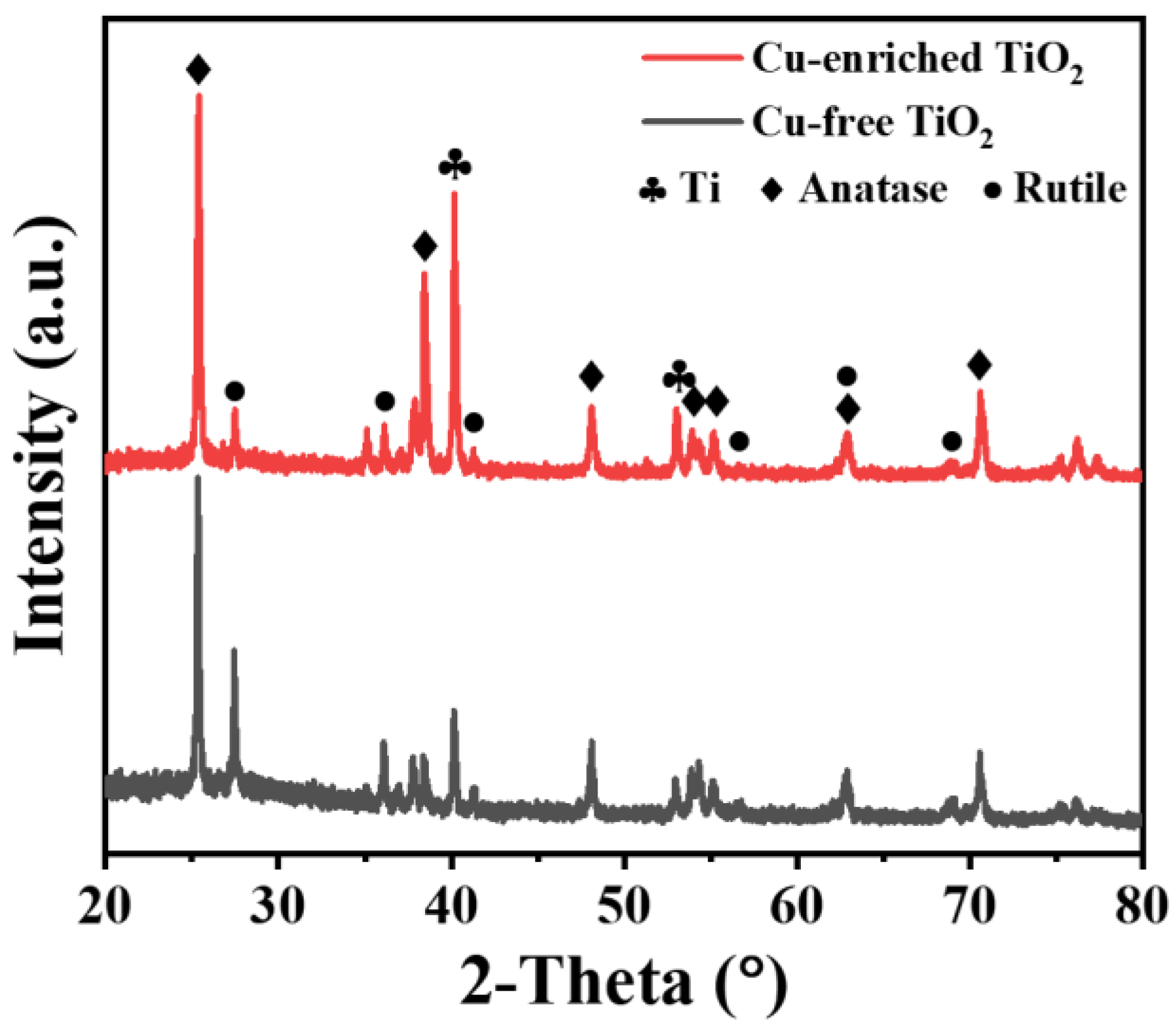
  • The addition of Na2Cu-EDTA results in a reduced rutile to anatase ratio in the resultant TiO2 coating.
  • The Cu-enriched TiO2 coating is less defective relative to the Cu-free coating, which may thus exhibit enhanced corrosion resistance.
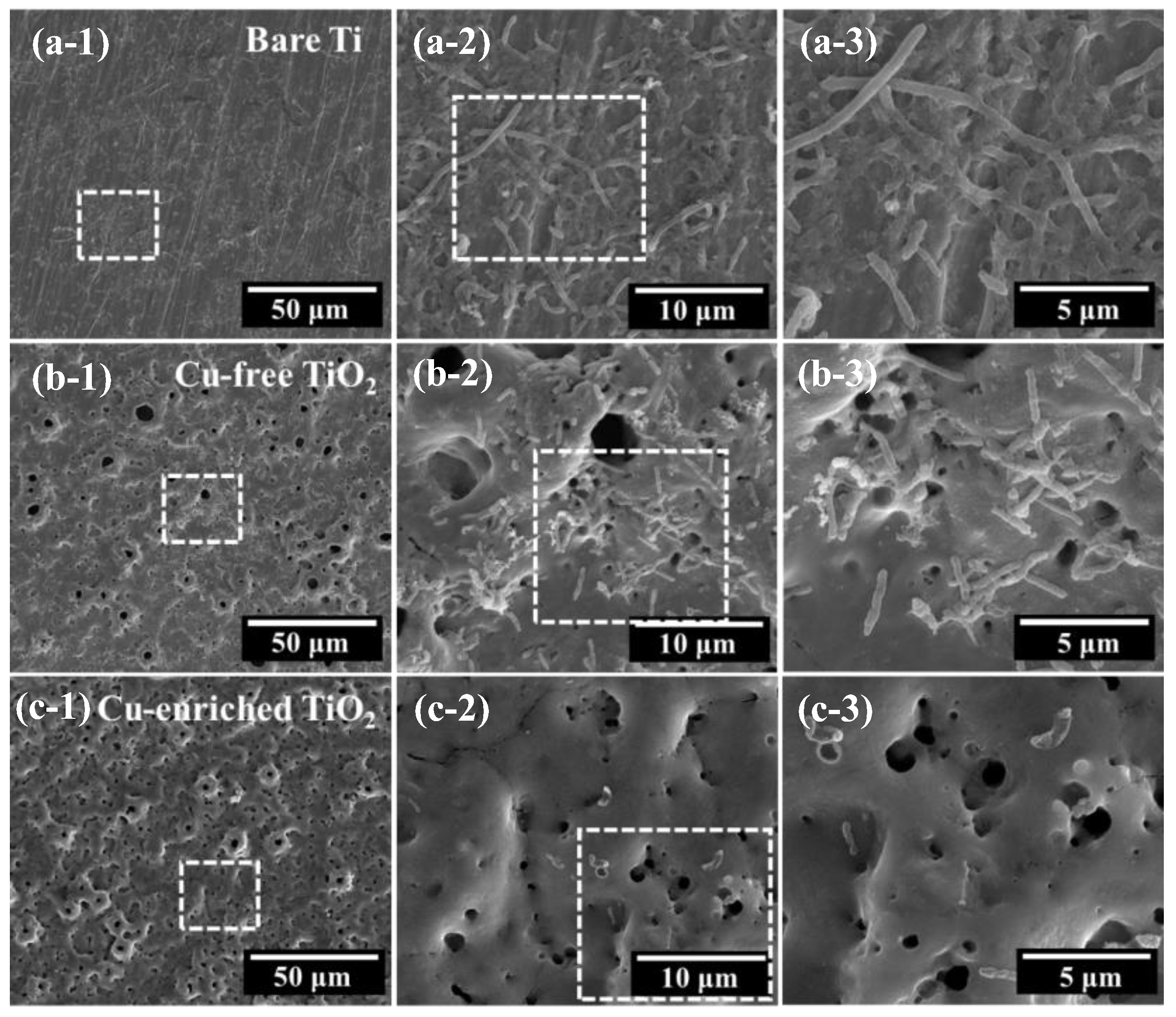
  • The Cu enrichment of TiO2 benefits its antifouling capability against SRB.

Supplementary Materials

The following supporting information can be downloaded at: https://www.mdpi.com/article/10.3390/coatings13061099/s1, Figure S1: (a) SEM micrographs along with the binary images based on standard threshold seg-mentation method; (b) statistic result of porosity; Figure S2: (a) statistic result of icorr and Ecorr; (b) statistic result of total resistance (Rtotal = Rcoat + Rct); Table S1: Porosity of Ti-based Cu modified micro-arc oxidation coatings.

Author Contributions

Conceptualization, Y.L. and X.Z.; methodology, Y.L. and Y.C.; investigation, Y.C.; resources, Z.D.; data curation, Y.L., Y.C., X.M. and X.J.; writing—original draft preparation, Y.L. and Y.C.; writing—review and editing, Z.D. and X.Z.; supervision, X.Z.; funding acquisition, Z.D. and X.Z. All authors have read and agreed to the published version of the manuscript.

Funding

The National Natural Science Foundation of China (No. 52001128).

Institutional Review Board Statement

Not applicable.

Informed Consent Statement

Not applicable.

Data Availability Statement

All research data supporting this publication are directly available within this publication.

Acknowledgments

The authors wish to thank the National Natural Science Foundation of China (No. 52001128) for support. The authors also thank the technical support from the Analytical and Testing Centre in Huazhong University of Science and Technology, the Instrumental analysis & research center of Shanghai Yanku, XFNANO Company (Nanjing, China), Shiyanjia Lab (www.shiyanjia.com (accessed on 24 March 2023)), Experiment Centre for Advanced Manufacturing and Technology in the School of Mechanical Science & Engineering of HUST and Nanoscale Characterization & Devices (CNCD), Wuhan National Laboratory for Optoelectronics (WNLO) of HUST.

Conflicts of Interest

The authors declare no conflict of interest.

References

  1. Schutz, R.W.; Watkins, H.B. Recent developments in titanium alloy application in the energy industry. Mater. Sci. Eng. A Struct. Mater. Prop. Microstruct. Process. 1998, 243, 305–315. [Google Scholar] [CrossRef]
  2. Liu, Q.; Song, S.; Li, D.; Bai, Q. Research and Development of Titanium Alloy OCTG Application in Energy Industry. Oil Field Equip. 2014, 43, 88–94. [Google Scholar]
  3. Yao, J.; Wang, Y.; Wu, G.; Sun, M.; Wang, M.; Zhang, Q. Growth characteristics and properties of micro-arc oxidation coating on SLM-produced TC4 alloy for biomedical applications. Appl. Surf. Sci. 2019, 479, 727–737. [Google Scholar] [CrossRef]
  4. Barrino, F.; De La Rosa-Ramírez, H.; Schiraldi, C.; López-Martínez, J.; Samper, M.D. Preparation and Characterization of New Bioplastics Based on Polybutylene Succinate (PBS). Polymers 2023, 15, 1212. [Google Scholar] [CrossRef]
  5. Keasler, V.; De Paula, R.M.; Nilsen, G.; Grunwald, L.; Tidwell, T.J. 23—Biocides Overview and Applications in Petroleum Microbiology. In Trends in Oil and Gas Corrosion Research and Technologies; El-Sherik, A.M., Ed.; Woodhead Publishing: Boston, MA, USA, 2017; pp. 539–562. [Google Scholar]
  6. Venzlaff, H.; Enning, D.; Srinivasan, J.; Mayrhofer, K.J.J.; Hassel, A.W.; Widdel, F.; Stratmann, M. Accelerated cathodic reaction in microbial corrosion of iron due to direct electron uptake by sulfate-reducing bacteria. Corros. Sci. 2013, 66, 88–96. [Google Scholar] [CrossRef] [Green Version]
  7. Zhang, C.; Wen, F.; Cao, Y. Progress in Research of Corrosion and Protection by Sulfate-Reducing Bacteria. In Proceedings of the 3rd International Conference on Environmental Science And Information Application Technology Esiat 2011, Beijing, China, 18–19 June 2011; Volume 10, pp. 1177–1182. [Google Scholar]
  8. Qi, Y.; Liang, W.; Miao, Q.; Lin, H.; An, H.; Liu, Y.; Zuo, S.; Ma, H. Corrosion behavior and antifouling ability of Cu-Zn-Al/Zn-Al composite coating on Q235 steel. Surf. Coat. Technol. 2021, 405, 126614. [Google Scholar] [CrossRef]
  9. Tian, J.J.; Xu, K.W.; Hu, J.H.; Zhang, S.J.; Cao, G.Q.; Shao, G.S. Durable self-polishing antifouling Cu-Ti coating by a micron-scale Cu/Ti laminated microstructure design. J. Mater. Sci. Technol. 2021, 79, 62–74. [Google Scholar] [CrossRef]
  10. Zhang, J.; Wang, Y.; Zhou, S.; Wang, Y.; Wang, C.; Guo, W.; Lu, X.; Wang, L. Tailoring self-lubricating, wear-resistance, anticorrosion and antifouling properties of Ti/(Cu, MoS2)-DLC coating in marine environment by controlling the content of Cu dopant. Tribol. Int. 2020, 143, 106029. [Google Scholar] [CrossRef]
  11. Zhang, X.; Wu, Y.; Wang, J.; Xia, X.; Lv, Y.; Cai, G.; Liu, H.; Xiao, J.; Liu, B.; Dong, Z. Microstructure, formation mechanism and antifouling property of multi-layered Cu-incorporated Al2O3 coating fabricated through plasma electrolytic oxidation. Ceram. Int. 2019, 46, 2901–2909. [Google Scholar] [CrossRef]
  12. Yuan, J.P.; Li, W.; Wang, C. Effect of the La alloying addition on the antibacterial capability of 316L stainless steel. Mater. Sci. Eng. C 2013, 33, 446–452. [Google Scholar] [CrossRef]
  13. Li, Y.; Feng, S.; Liu, H.; Tian, X.; Xia, Y.; Li, M.; Xu, K.; Yu, H.; Liu, Q.; Chen, C. Bacterial distribution in SRB biofilm affects MIC pitting of carbon steel studied using FIB-SEM. Corros. Sci. 2020, 167, 108512. [Google Scholar] [CrossRef]
  14. Wang, P.; Lu, Z.; Zhang, D. Slippery liquid-infused porous surfaces fabricated on aluminum as a barrier to corrosion induced by sulfate reducing bacteria. Corros. Sci. 2015, 93, 159–166. [Google Scholar] [CrossRef]
  15. Liu, F.; Zhang, J.; Sun, C.; Yu, Z.; Hou, B. The corrosion of two aluminium sacrificial anode alloys in SRB-containing sea mud. Corros. Sci. 2014, 83, 375–381. [Google Scholar] [CrossRef]
  16. Gu, T.; Jia, R.; Unsal, T.; Xu, D. Toward a better understanding of microbiologically influenced corrosion caused by sulfate reducing bacteria. J. Mater. Sci. Technol. 2019, 35, 631–636. [Google Scholar] [CrossRef]
  17. Rao, T.S.; Kora, A.J.; Anupkumar, B.; Narasimhan, S.V.; Feser, R. Pitting corrosion of titanium by a freshwater strain of sulphate reducing bacteria (Desulfovibrio vulgaris). Corros. Sci. 2005, 47, 1071–1084. [Google Scholar] [CrossRef]
  18. Zhang, X.; Peng, Z.; Lu, X.; Lv, Y.; Cai, G.; Yang, L.; Dong, Z. Microstructural evolution and biological performance of Cu-incorporated TiO2 coating fabricated through one-step micro-arc oxidation. Appl. Surf. Sci. 2019, 508, 144766. [Google Scholar] [CrossRef]
  19. Zhang, Y.; Li, Y.; Lv, Y.; Zhang, X.; Dong, Z.; Yang, L.; Zhang, E. Ag distribution and corrosion behaviour of the plasma electrolytic oxidized antibacterial Mg-Ag alloy. Electrochim. Acta 2022, 411, 140089. [Google Scholar] [CrossRef]
  20. Li, K.; Xia, C.; Qiao, Y.; Liu, X. Dose-response relationships between copper and its biocompatibility/antibacterial activities. J. Trace Elem. Med. Biol. 2019, 55, 127–135. [Google Scholar] [CrossRef]
  21. Cerchier, P.; Pezzato, L.; Moschin, E.; Coelho, L.B.; Olivier, M.G.M.; Moro, I.; Magrini, M. Antifouling properties of different Plasma Electrolytic Oxidation coatings on 7075 aluminium alloy. Int. Biodeterior. Biodegrad. 2018, 133, 70–78. [Google Scholar] [CrossRef]
  22. Wang, J.; Yang, C.; Liu, S.; Fang, S.; Xia, C. Novel Antifouling Technology Research: Progress and Prospects. Sci. Sin. Vitae 2016, 46, 1079–1084. [Google Scholar]
  23. Qian, P.Y.; Xu, Y.; Fusetani, N. Natural products as antifouling compounds: Recent progress and future perspectives. Biofouling 2010, 26, 223–234. [Google Scholar] [CrossRef] [PubMed]
  24. Li, H.; Yan, Z.; Cao, L. Bake hardening behavior and precipitation kinetic of a novel Al-Mg-Si-Cu aluminum alloy for lightweight automotive body. Mater. Sci. Eng. A 2018, 728, 88–94. [Google Scholar] [CrossRef]
  25. Zhang, X.; Zhang, T.; Lv, Y.; Zhang, Y.; Lu, X.; Xiao, J.; Ma, C.; Li, Z.; Dong, Z. Enhanced uniformity, corrosion resistance and biological performance of Cu-incorporated TiO2 coating produced by ultrasound-auxiliary micro-arc oxidation. Appl. Surf. Sci. 2021, 569, 150932. [Google Scholar] [CrossRef]
  26. Zhang, X.; Yu, Y.; Jiang, D.; Jiao, Y.; Wu, Y.; Peng, Z.; Zhou, J.; Wu, J.; Dong, Z. Synthesis and characterization of a bi-functional hydroxyapatite/Cu-doped TiO2 composite coating. Ceram. Int. 2019, 45, 6693–6701. [Google Scholar] [CrossRef]
  27. Zhang, X.; Li, J.; Wang, X.; Wang, Y.; Hang, R.; Huang, X.; Tang, B.; Chu, P.K. Effects of copper nanoparticles in porous TiO2 coatings on bacterial resistance and cytocompatibility of osteoblasts and endothelial cells. Mater. Sci. Eng. C 2018, 82, 110–120. [Google Scholar] [CrossRef]
  28. He, X.; Zhang, G.; Wang, X.; Hang, R.; Huang, X.; Qin, L.; Tang, B.; Zhang, X. Biocompatibility, corrosion resistance and antibacterial activity of TiO2/CuO coating on titanium. Ceram. Int. 2017, 43, 16185–16195. [Google Scholar] [CrossRef]
  29. Zhou, P.; Yang, L.; Hou, Y.; Duan, G.; Yu, B.; Li, X.; Zhai, Y.; Zhang, B.; Zhang, T.; Wang, F. Grain refinement promotes the formation of phosphate conversion coating on Mg alloy AZ91D with high corrosion resistance and low electrical contact resistance. Corros. Commun. 2021, 1, 47–57. [Google Scholar] [CrossRef]
  30. Yang, L.; Zhou, X.R.; Curioni, M.; Pawar, S.; Liu, H.; Fan, Z.Y.; Scamans, G.; Thompson, G. Corrosion Behavior of Pure Magnesium with Low Iron Content in 3.5 wt% NaCl Solution. J. Electrochem. Soc. 2015, 162, C362–C368. [Google Scholar] [CrossRef]
  31. Buchheit, R.G. A Compilation of Corrosion Potentials Reported for Intermetallic Phases in Aluminum Alloys. J. Electrochem. Soc. 1995, 142, 3994–3996. [Google Scholar] [CrossRef]
  32. Guo, H.; Liu, Z.; Wang, Y.; Li, J. Tribological mechanism of micro-arc oxidation coatings prepared by different electrolyte systems in artificial seawater. Ceram. Int. 2021, 47, 7344–7352. [Google Scholar] [CrossRef]
  33. Oliveira, F.G.; Ribeiro, A.R.; Perez, G.; Archanjo, B.S.; Gouvea, C.P.; Araújo, J.R.; Campos, A.P.C.; Kuznetsov, A.; Almeida, C.M.; Maru, M.M.; et al. Understanding growth mechanisms and tribocorrosion behaviour of porous TiO2 anodic films containing calcium, phosphorous and magnesium. Appl. Surf. Sci. 2015, 341, 1–12. [Google Scholar] [CrossRef] [Green Version]
  34. Rokosz, K.; Hryniewicz, T.; Matysek, D.; Raaen, S.; Valicek, J.; Dudek, L.; Harnicarova, M. SEM, EDS and XPS Analysis of the Coatings Obtained on Titanium after Plasma Electrolytic Oxidation in Electrolytes Containing Copper Nitrate. Materials 2016, 9, 318. [Google Scholar] [CrossRef]
  35. Yoshimura, R.; Konno, T.J.; Abe, E.; Hiraga, K. Transmission electron microscopy study of the evolution of precipitates in aged Al–Li–Cu alloys: The θ′ and T1 phases. Acta Mater. 2003, 51, 4251–4266. [Google Scholar] [CrossRef]
  36. Dejiu, S.; Jingrui, C.; Guolong, L.; Donglei, H.; Lailei, W.; Haojie, M.; Yonghong, X.; He, C.; Yaqian, Y. Effect of ultrasonic on microstructure and growth characteristics of micro-arc oxidation ceramic coatings on 6061 aluminum alloy. Vacuum 2014, 99, 143–148. [Google Scholar] [CrossRef]
  37. Qu, L.; Li, M.; Liu, M.; Zhang, E.; Ma, C. Microstructure and corrosion resistance of ultrasonic micro-arc oxidation biocoatings on magnesium alloy. J. Adv. Ceram. 2013, 2, 227–234. [Google Scholar] [CrossRef] [Green Version]
  38. Lv, Y.; Sun, S.; Zhang, X.; Lu, X.; Dong, Z. Construction of multi-layered Zn-modified TiO2 coating by ultrasound-auxiliary micro-arc oxidation: Microstructure and biological property. Mater. Sci. Eng. C 2021, 131, 112487. [Google Scholar] [CrossRef] [PubMed]
  39. Lv, Y.; Zhang, C.; Zhang, Y.; Wang, Q.; Zhang, X.; Dong, Z. Microstructure and Corrosion Resistance of Plasma Electrolytic Oxidized Recycled Mg Alloy. Acta Metall. Sin. Engl. Lett. 2022, 35, 961–974. [Google Scholar] [CrossRef]
  40. Wang, S.; Deng, L.; Lv, Y.; Zhang, T.; Zhang, X.; Dong, Z.; Cai, G. Construction of antifouling Cu-modified TiO2 coating via micro-arc oxidation: The influence of Cu content. Surf. Coat. Technol. 2023, 454, 129197. [Google Scholar] [CrossRef]
  41. Permeh, S.; Lau, K.; Duncan, M. Effect of crevice morphology on SRB activity and steel corrosion under marine foulers. Bioelectrochemistry 2021, 142, 107922. [Google Scholar] [CrossRef]
  42. Li, M.; Seyeux, A.; Wiame, F.; Marcus, P.; Światowska, J. Insights on the Al-Cu-Fe-Mn intermetallic particles induced pitting corrosion of Al-Cu-Li alloy. Corros. Sci. 2020, 176, 109040. [Google Scholar] [CrossRef]
  43. Hussein, R.O.; Nie, X.; Northwood, D.O. An investigation of ceramic coating growth mechanisms in plasma electrolytic oxidation (PEO) processing. Electrochim. Acta 2013, 112, 111–119. [Google Scholar] [CrossRef]
  44. Zhu, L.; Guo, Z.; Zhang, Y.; Li, Z.; Sui, M. A mechanism for the growth of a plasma electrolytic oxide coating on Al. Electrochim. Acta 2016, 208, 296–303. [Google Scholar] [CrossRef]
  45. Kaseem, M.; Fatimah, S.; Nashrah, N.; Ko, Y.G. Recent progress in surface modification of metals coated by plasma electrolytic oxidation: Principle, structure, and performance. Prog. Mater. Sci. 2021, 117, 100735. [Google Scholar] [CrossRef]
  46. Kamil, M.P.; Kaseem, M.; Ko, Y.G. Soft plasma electrolysis with complex ions for optimizing electrochemical performance. Sci. Rep. 2017, 7, 44458. [Google Scholar] [CrossRef] [Green Version]
  47. Li, C.Y.; Fan, X.L.; Zeng, R.C.; Cui, L.Y.; Li, S.Q.; Zhang, F.; He, Q.K.; Kannan, M.B.; Jiang, H.W.; Chen, D.C.; et al. Corrosion resistance of in-situ growth of nano-sized Mg(OH)2 on micro-arc oxidized magnesium alloy AZ31-Influence of EDTA. J. Mater. Sci. Technol. 2019, 35, 1088–1098. [Google Scholar] [CrossRef]
  48. Lu, X.; Mohedano, M.; Blawert, C.; Matykina, E.; Arrabal, R.; Kainer, K.U.; Zheludkevich, M.L. Plasma electrolytic oxidation coatings with particle additions—A review. Surf. Coat. Technol. 2016, 307, 1165–1182. [Google Scholar] [CrossRef]
  49. Zhang, X.; Li, C.; Yu, Y.; Lu, X.; Lv, Y.; Jiang, D.; Peng, Z.; Zhou, J.; Zhang, X.; Sun, S.; et al. Characterization and property of bifunctional Zn-incorporated TiO2 micro-arc oxidation coatings: The influence of different Zn sources. Ceram. Int. 2019, 45, 19747–19756. [Google Scholar] [CrossRef]
  50. Zhang, X.; Yang, L.; Lu, X.; Lv, Y.; Jiang, D.; Yu, Y.; Peng, Z.; Dong, Z. Characterization and property of dual-functional Zn-incorporated TiO2 micro-arc oxidation coatings: The influence of current density. J. Alloys Compd. 2019, 810, 151893. [Google Scholar] [CrossRef]
  51. Treacy, G.M.; Rudd, A.L.; Breslin, C.B. Electrochemical behaviour of aluminium in the presence of EDTA-containing chloride solutions. J. Appl. Electrochem. 2000, 30, 675–683. [Google Scholar] [CrossRef]
  52. Hanaor, D.A.H.; Sorrell, C.C. Review of the anatase to rutile phase transformation. J. Mater. Sci. 2011, 46, 855–874. [Google Scholar] [CrossRef] [Green Version]
  53. Peng, C.; Cao, G.; Gu, T.; Wang, C.; Wang, Z.; Sun, C. The corrosion behavior of the 6061 Al alloy in simulated Nansha marine atmosphere. J. Mater. Res. Technol. 2022, 19, 709–721. [Google Scholar] [CrossRef]
  54. Tweddle, D.; Johnson, J.A.; Kapoor, M.; Bikmukhametov, I.; Mileski, S.; Carsley, J.E.; Thompson, G.B. Atomic-scale Clustering in a High-strength Al-Mg-Si-Cu Alloy. Materialia 2022, 26, 101567. [Google Scholar] [CrossRef]
  55. Liu, J.; Li, F.; Liu, C.; Wang, H.; Ren, B.; Yang, K.; Zhang, E. Effect of Cu content on the antibacterial activity of titanium–copper sintered alloys. Mater. Sci. Eng. C 2014, 35, 392–400. [Google Scholar] [CrossRef] [PubMed]
  56. Cui, M.; Jo, Y.H.; Kayani, S.H.; Kim, H.-W.; Lee, J.-H. Effects of Cu additions on the precipitation activation energy and mechanical properties of prestrained Al–Mg–Si alloys. J. Mater. Res. Technol. 2022, 20, 2629–2637. [Google Scholar] [CrossRef]
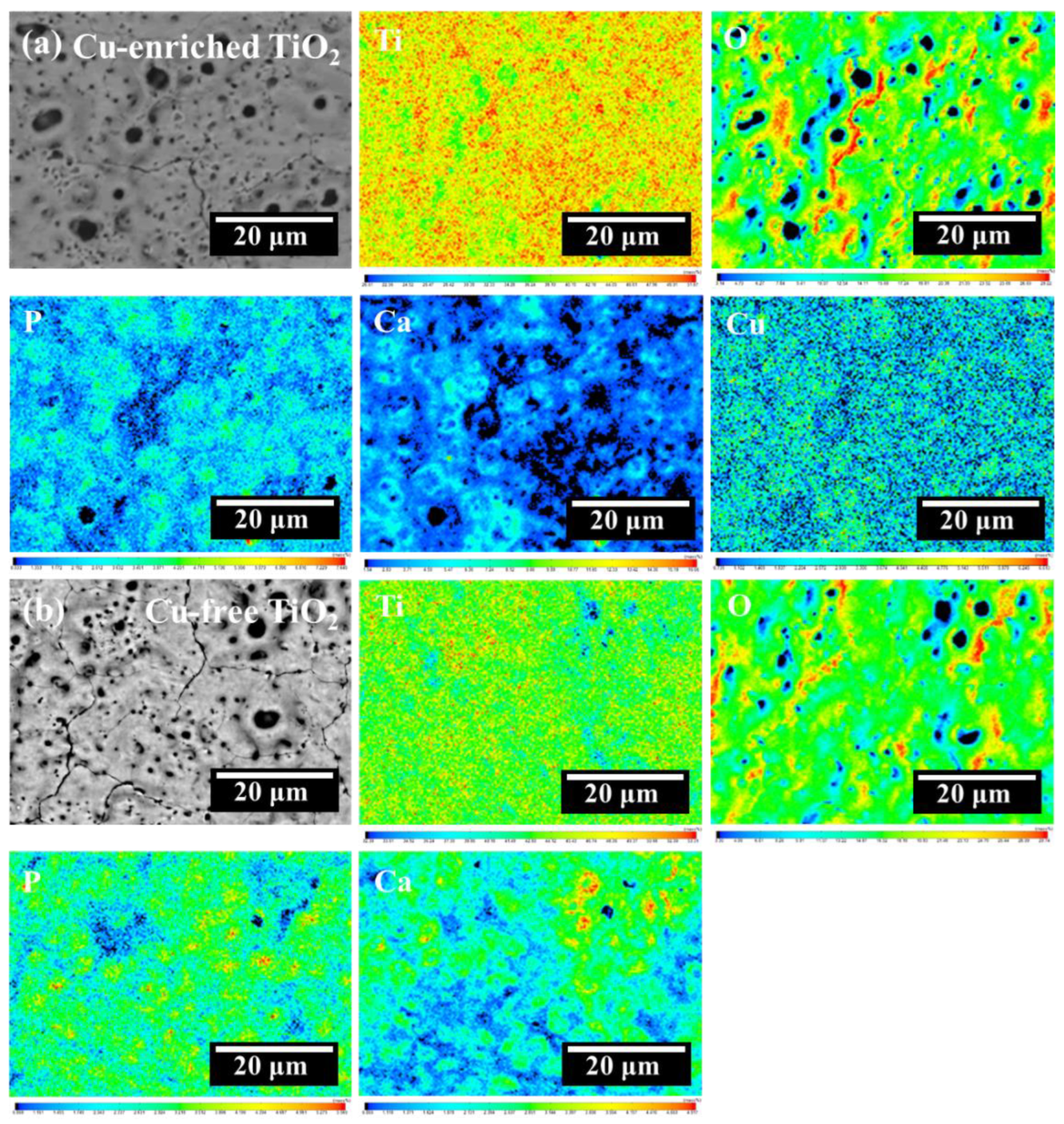
Figure 1. Voltage–time curves during ultrasound-auxiliary micro-arc oxidation process.
Coatings 13 01099 g001
Figure 2. SEM micrographs of coating surfaces: (a,c,e) Cu-enriched TiO2 coating; (b,d,f) Cu-free TiO2 coating.
Coatings 13 01099 g002
Figure 3. EPMA analysis of coating surfaces: (a) SEM micrograph of Cu-enriched TiO2 coating with the corresponding elemental maps in the sequence of Ti, Cu, O, P and Ca; (b) SEM micrograph of Cu-free TiO2 coating with the corresponding elemental maps in the sequence of Ti, O, P and Ca.
Coatings 13 01099 g003
Figure 4. SEM micrographs of cross-sectional views of the coatings: (a,b) Cu-enriched TiO2 coating; (c,d) Cu-free TiO2 coating.
Coatings 13 01099 g004
Figure 5. EPMA analysis of cross sections of both coatings: (a) SEM micrograph of Cu-enriched TiO2 coating with the corresponding elemental maps in the sequence of Ti, Cu, O, P and Ca; (b) SEM micrograph of Cu-free TiO2 coating with the corresponding elemental maps in the sequence of Ti, O, P and Ca.
Coatings 13 01099 g005
Figure 6. TFXRD patterns of Cu-enriched and Cu-free TiO2 coatings.
Coatings 13 01099 g006
Figure 7. (a) Water contact angles; (b) surface topography of Cu-enriched and Cu-free TiO2 coatings.
Coatings 13 01099 g007
Figure 8. Potentiodynamic polarization curves of both Cu-enriched and Cu-free TiO2 coatings with bare Ti as a comparison.
Coatings 13 01099 g008
Figure 9. (a) Nyquist plots of EIS; (b) Bode plots of EIS; (c) the equivalent circuit (EC) model for EIS.
Coatings 13 01099 g009
Figure 10. SEM micrographs of SRB on the surfaces of (a) bare Ti, (b) Cu-free TiO2 coatings and (c) Cu-enriched TiO2 coatings.
Coatings 13 01099 g010
Table 1. Quantitative analysis of chemical compositions of both Cu-enriched and Cu-free TiO2 coatings.
ElementContent (wt.%)
TiOCaPCu
Cu-enriched TiO252.4634.005.055.952.54
Cu-free TiO255.0434.605.145.20---
Table 2. Tafel slopes (βa and βc), corrosion current densities (icorr) and corrosion potentials (Ecorr) derived from the potentiodynamic polarization curves shown in Figure 8.
Samplesβa (mV)βc (mV)icorr (A/cm2)Ecorr (V)
Bare Ti177.65133.837.933 × 10−7−0.26
Cu-free TiO2166.8856.731.509 × 10−80.084
Cu-enriched TiO2363.6749.604.957 × 10−90.203
Table 3. Fitting results of EIS data shown in Figure 9.
SamplesRs
(Ω·cm2)
CPEcoat-Q
(F/cm2)
CPEcoat-nRcoat
(Ω·cm2)
CPEdl-Q
(F/cm2)
CPEdl-nRct
(Ω·cm2)
Bare Ti5.612.726 × 10−50.85084362.719 × 10−40.6474.212 × 104
Cu-free TiO28.615.193 × 10−40.70272.23.546 × 10−50.7232.085 × 105
Cu-enriched TiO27.024.084 × 10−40.72767.22.743 × 10−50.7472.486 × 105
Disclaimer/Publisher’s Note: The statements, opinions and data contained in all publications are solely those of the individual author(s) and contributor(s) and not of MDPI and/or the editor(s). MDPI and/or the editor(s) disclaim responsibility for any injury to people or property resulting from any ideas, methods, instructions or products referred to in the content.

