1. Introduction
A microbial fuel cell (MFC) is a device that utilizes electricity-producing microorganisms to decompose an organic matrix to generate electric energy. MFCs are an emerging technology because of their unique way of generating electricity by using microbes to decompose organic matter. There is no environmental pollution in their power generation process, which is a green and pollution-free way of generating power [
1,
2,
3].
However, the practical application of MFCs in wastewater treatment and energy recovery still faces many problems, such as low power generation levels and a lack of energy storage. As the carrier of electricity-producing microorganisms, the anode material of the MFC would not only affect the electricity-producing bacteria attached to the anode surface but also affect the electron transfer from the electricity-producing bacteria to the anode surface. Thus, the anode material plays a crucial role in improving the output and energy storage of MFCs. Therefore, anode materials with potential have been selected for research to enhance the performance of MFCs. This has great significance in improving the power generation and energy storage capacity of MFCs [
4,
5,
6].
The recently proposed capacitive bioanode is a new concept that combines capacitive electrodes with biological anodes. The constructed MFC produces electricity and stores energy simultaneously and provides a large output current. The advantage of capacitive bioanodes is that capacitive bioanodes can produce and store electricity simultaneously. When electricity is not needed, the charge can be stored in the capacitive anode first, and more current can be released quickly when electricity is needed. Pseudo-capacitive materials have been preferred for capacitive anodes because of their large capacitance values. Therefore, in recent years, when modifying the anode of MFCs, a large number of pseudo-capacitive materials have been used by experts and scholars to improve the energy storage performance of MFCs.
Metal oxides are the most common pseudo-capacitive materials as the MFC anode due to their redox reversibility, large theoretical capacitance, and good environmental stability [
7,
8]. Peng et al. [
9] prepared an anode by rolling Fe
3O
4 onto activated carbon on the stainless steel mesh. The experiment results showed that the AcFeM anode exhibited a 41% higher cumulative charge of 3566 ± 32 C m
−2 and a 32% higher net capacitance charge of 389 ± 18 C m
−2 than those of the AcM control (2529 ± 22 and 294 ± 30 C m
−2). This indicates that the energy storage performance of the anode was improved by the pseudo-capacitive Fe
3O
4 material. Gong et al. [
10] prepared a MnO
2-modified carbon paper electrode by the in situ deposition method. The electrochemical performance of the MnO
2-modified carbon paper electrode was increased considerably compared with the unmodified electrode. Lv et al. [
11] constructed an MFC containing pseudo-capacitive anode materials to store bio-electrons generated from microbial substrate oxidation and accumulated charge release upon requirement. The results showed that the increased anode capacitance led to storing more energy, and the average power dissipated.
These studies have shown that capacitive anodes could improve the transient storage of electrical charge in the bioanodes, demonstrating the possibility of using the MFC simultaneously to convert and store bioenergy. Among various metal oxides, Wang et al. [
12] electrodeposited manganese dioxide on a carbon felt (CF) substrate as the MFC anode. They obtained a maximum power density of 16.47 W/m
3, 3.5 times higher than the blank anode. Zhang et al. [
13] also prepared a CF/MnO
2 anode by electrodeposition. They achieved a maximum power density of 3580 W/m
2, which was much higher than that of the MFC without modification by MnO
2 (2870 W/m
2), and its maximum power density was also higher than that of the RuO
2-modified MFC [
14]. Chen et al. [
15] prepared composite materials with different mass fractions of manganese dioxide as MFC anodes. The experimental results showed that the power of the bioanode modified with 75% mass fraction was the highest (767.3 mW/m
2), and the Coulomb efficiency also increased by 20.7%. Although manganese dioxide has good capacitive performance, its poor conductivity will affect the electricity generation and energy storage performance of MFCs. Obviously, it was not enough to modify only by using pseudo-capacitive MnO
2, which greatly limits microbial attachment. Thus, MnO
2 must be compounded with other materials to better improve the overall performance of MFCs. Recently, carbon nanotubes (CNTs) have emerged as new smart materials for bioanodes [
16,
17,
18]. Because of the special structure of CNTs, they have been widely used in the field of MFCs. Firstly, CNTs have tubular structures whose endings can infiltrate into the microbial species and promote electron transfer from the electrically-producing bacteria to the anode. Secondly, CNTs have rough surfaces that allow microbes to adhere to them. In addition, relevant studies have proven that combining metal oxides and CNTs can greatly improve the MFC anode’s performance. Duan et al. [
19] prepared a three-dimensional macroporous CNT–SnO
2 composite as an MFC anode. The discharge–charge experiments showed that the CNT–SnO
2 composite had a greater specific capacitance than the CNT electrode (382 versus 42.8 mF cm
−2) with a current density of 1 mA cm
−2. Mehdinia et al. [
20] constructed an MFC equipped with the composite anode of multi-walled CNTs/tin oxide (MWCNTs/SnO
2). The maximum power density of the MFC possessing the MWCNTs/SnO
2 anode was the highest (1421 mW m
−2) compared to the other two MFCs. Moreover, the excellent performance could be attributed to the synergetic effect between the CNTs and SnO
2 with good biocompatibility and improved electrical conductivity.
In this paper, a biocompatible and capacitive CF/CNT/MnO2 composite material was prepared as an MFC anode to improve output power and energy storage. The composite of these two materials could give full play to their respective advantages and make up for their shortcomings. On that basis, we utilized the capacitive bioanode capable of simultaneous electricity generation and energy storage in MFCs. These materials were characterized through scanning electron microscopy (SEM) and X-Ray diffraction (XRD). The performance of MFCs was tested by polarization analysis, cyclic voltammetry, and charge–discharge curves. With the high-capacitance anode, it was possible to simultaneously convert and store renewable energy in MFCs.
2. Experiment
2.1. Preparation of the CF/CNT/MnO2 Electrode
Approximately 10 g sodium dodecyl benzene sulfonate was added into a 1 L beaker and stirred until evenly dispersed. Then, a volumetric bottle was used to fill it with 10 g/L of the sodium dodecyl benzene sulfonate solution. Approximately 0.5 g MWCNTs (with a diameter of 40–60 nm and a length of 5 μm) were added into a 500 mL beaker containing the sodium dodecyl benzene sulfonate solution. The mixed solution was stirred for 2 h and then dispersed by ultrasonic for 1 h. After that, the prepared CNTs were absorbed with a glue-head dropper and slowly dropped onto the CF surface. Then, the CF was put in the oven to dry for 1 h, then repeatedly rinsed with a lot of distilled water. In the next step, the CF was applied again with the plastic head dropper. The above process was repeated 20 times so the CF could load CNT and CF/CNT electrodes.
Approximately 0.8 g of manganese sulfate powder was dissolved in distilled water, and then 2 g sodium sulfate powder was added into the manganese sulfate solution as a supporting electrolyte, which was stirred at a constant volume.
The titanium wire was sanded with 200 mesh sandpaper; then, the CF/CNT anode was attached to the titanium wire, and two stainless steel plates were placed on either side of the CF at a distance of about 2 cm to act as the cathode. The cathode area was kept larger than the anode in the solution.
The electrodeposition current density was 10 mA/cm2, and the electrodeposition time was 60 min. After electrodeposition, the electrode was washed repeatedly with distilled water and dried for use.
2.2. MFC Construction, Operation, and Testing
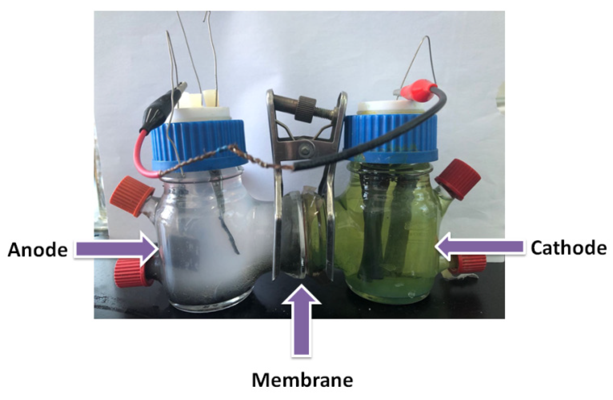
Assembly: The two-compartment microbial fuel cell (
Figure 1) is mainly composed of three parts: a cathode chamber, an anode chamber, and a proton exchange membrane. The two cylindrical slots are composed of two chambers sandwiched with a proton exchange membrane. The anode and cathode chambers are fixed with rubber washers and clamped tightly to ensure that the reactor does not leak.
Microorganisms were inoculated with an anode nutrient solution containing a carbon source (2.5 g/L sodium acetate). The bacteria used in this paper originated from activated sludge, which was composed of a variety of microorganisms and was completed through mixed culture in use. The inoculated bacteria in the anode chamber were obtained from another stable MFC reactor in the laboratory.
The MFC cathode solution is a 10 g/L potassium ferricyanide solution.
The prepared anode material was placed in the anode chamber, the cathode material was carbon rod, and the external circuit was connected with 5000 Ω resistance to start the MFC. The experimental operating temperature was 22 ± 3 °C; the anode and cathode liquid should be replaced regularly. The voltage and anode potential at both ends of the MFC were measured regularly. When the voltage at both ends basically did not change, microbial domestication was completed. After that, the performance of the MFC was tested.
2.3. Characterization and Measurements
In this paper, the cyclic voltammetry and charging and discharging curves were tested and studied with a three-electrode system. The modified anode was used as the working electrode, the platinum electrode was used as the counter electrode, and the saturated calomel electrode was used as the reference electrode. Data were recorded using the SP-240 electrochemical workstation of Biologic, Seyssinet-Pariset, France. In the charge–discharge tests, operation in open-circuit conditions (charging) was alternated at a set anodic potential (discharging) of −0.1 V. In this experiment, the D/Max2500 X-Ray diffractometer of Shimazu Company of Tokyo, Japan, was used to record the XRD patterns of the samples. To this end, for the Cu-K source, a tube flow of 40 mA and a tube pressure of 40 kV were selected. The 2θ scanning range was 20–80°. SEM was used to observe the microscopic surface morphology of the materials and the fracture and internal tissues of the samples. The SEM equipment used in this paper is an Inspect S50 scanning electron microscope (Inspect S50, LA, US). The test conditions were as follows: the acceleration voltage was 0.5–30 kV, the point resolution was 1.0 nm, the maximum diameter of the sample station was 50 mm, and the working distance was 10 mm.
3. Results and Discussion
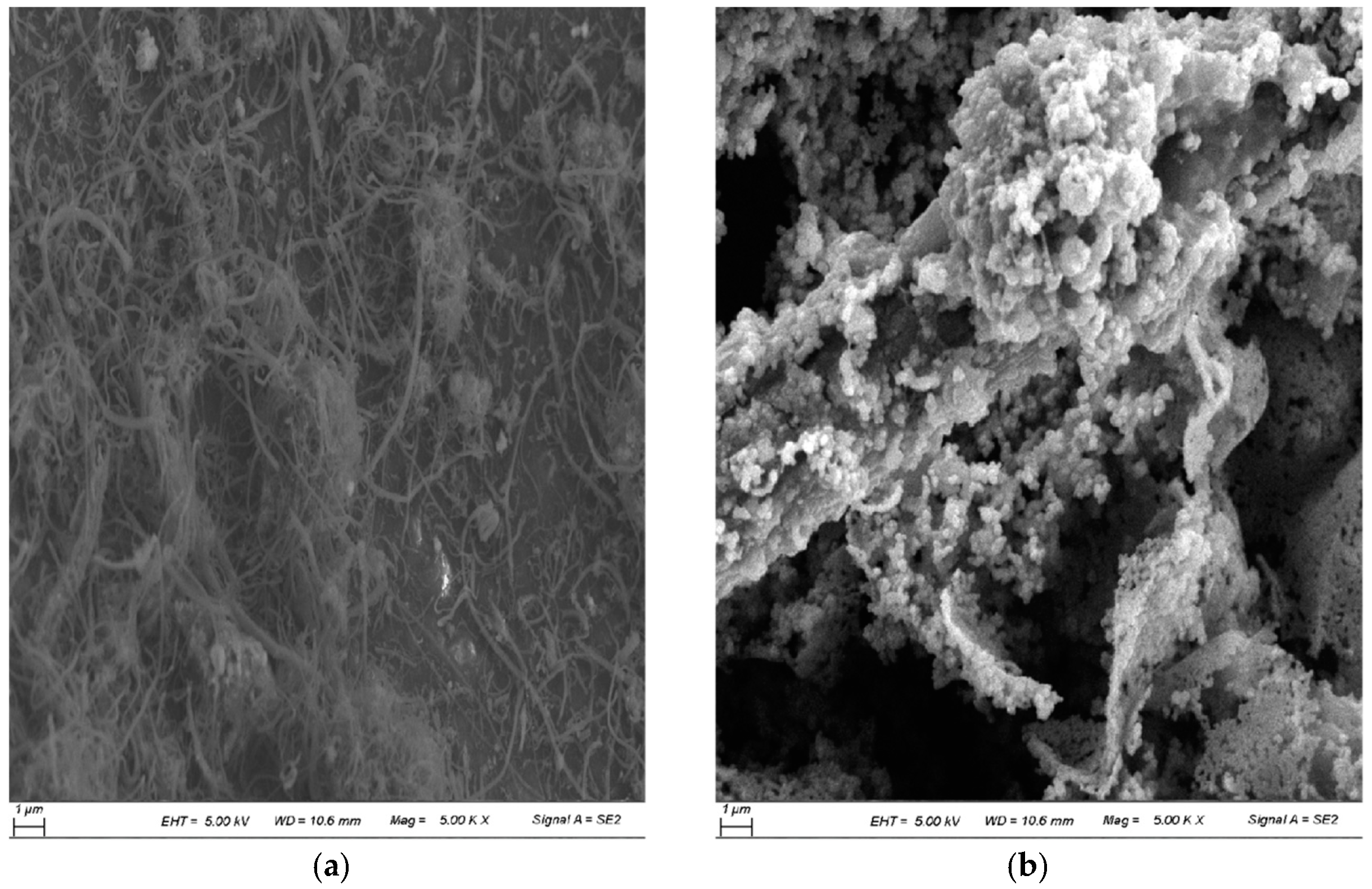
Figure 2 shows the SEM pictures of the prepared CF/CNT anode and the CF/CNT/MnO
2 composite anode. As shown in
Figure 2a, adding CNTs changed the morphology of the CF and formed a network structure on the carbon fiber. As active materials of the conductive network structure, the CNTs had a porous reticular structure, which was conducive to ion transfer in the solution. As seen in
Figure 2b, manganese dioxide appeared as agglomerated powder particles, which were tightly packed on CF fibers. The surfaces of the CF fiber and CNTs were uniformly covered by the MnO
2 with almost no bare areas. It was shown that the prepared active substances were spherical, and irregular polyhedron manganese dioxide increased the specific surface area of the anode. Moreover, the CF with spherical particles of the CNT/MnO
2 composite was prepared, facilitating the adhesion of microorganisms. Thus, the number of microorganisms on the anode surface increased, which further increased the power density of the MFC.
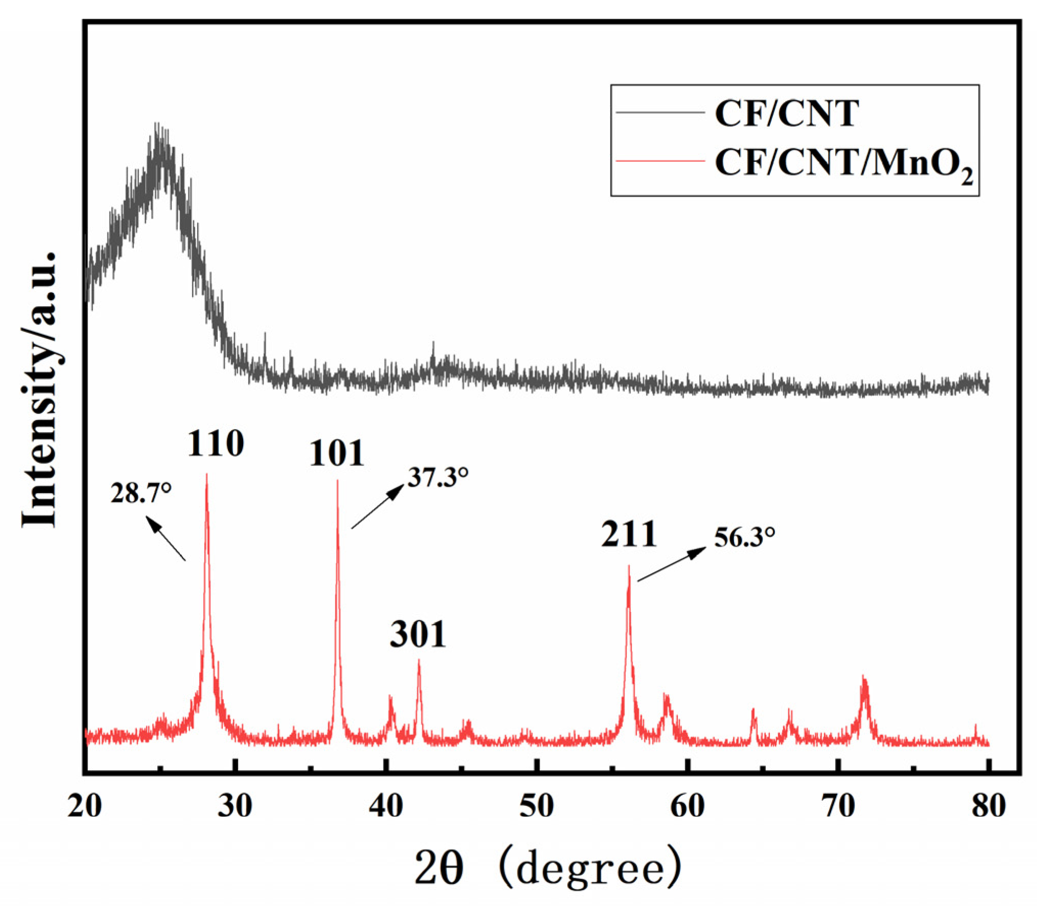
The XRD patterns of the two composites are shown in
Figure 3. In the pattern of the modified anode, the position of the peak was observed at around 2θ = 28.7°, 37.3°, and 56.3°, corresponding to the crystal planes of (110), (101), and (211), respectively. The positions of the diffraction peaks are attributed to the standard spectra of standard spinel manganese dioxide (JCPDS 24-0735). As shown in
Figure 3, in the pattern of the CF/CNT anode, the diffraction peak could be found at around 2θ = 25.9° due to the characteristic diffraction peak of CNTs.
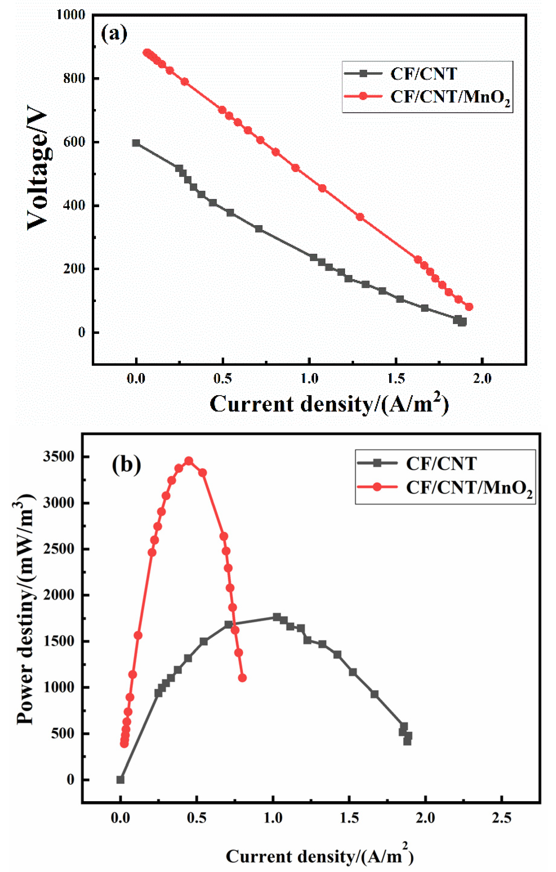
Figure 4a shows the polarization curves of the MFC with two different anodes, and
Figure 4b displays the power density curves of the MFC applied to two different anodes. The open circuit voltage (OCV) represents the maximum output voltage of the MFC. The OCV of the MFC applied to two anodes had obvious differences. The maximum OCV of the MFC applied to the CF/CNT/MnO
2 bioanode reached 899 mV, and the MFC equipped with the CF/CNT anode (611 mV) was much smaller. The polarization curve trend of the MFC also had great differences. The polarization degree of the MFC equipped with the CF/CNT/MnO
2 bioanode was also better than that of the CF/CNT anode. The current density of the MFC equipped with the CF/CNT/MnO
2 bioanode was larger under the same voltage value, and the polarization performance of the CF/CNT/MnO
2 bioanode was good. For example, when the output voltage was 450 mV, the current density of the MFC equipped with the CF/CNT/MnO
2 bioanode was 1.19 A m
−2, 4.1 times higher than that of the CF/CNT anode (0.29 A m
−2). According to
Figure 4b, in the MFC system with the same conditions except for the anode, the maximum power densities of the MFC equipped with the CF/CNT/MnO
2 bioanode and the CF/CNT anode were 3471.6 and 1772.6 mW m
−3, respectively. The maximum power density of the MFC with the CF/CNT/MnO
2-modified bioanode was 1.96 times higher than that of the CF/CNT anode. The experimental results showed that the MFC equipped with the pseudo-capacitive material had not only a high output voltage but also a large power density. This indicates that the pseudo-capacitive-modified CF anode enabled more microorganisms to reside on the anode surface to form a stable biofilm. Adhesion of a large number of electricity-producing bacteria was conducive to improving the electricity-producing performance of the electrode, which generated more electrons to be stored in the electrode and further improved the output power of the MFC. In addition, the CNT/MnO
2 composite biological anode obtained better output power performance in the MFC. This is attributed to the synergistic effect of MnO
2 and CNT. CNT was conducive to electron transfer, which could promote the metabolism of electric-producing microorganisms. Meanwhile, CNT also positively affected the stability of microbial colonies, facilitating electron transfer between electric-producing bacteria and the anode [
21,
22,
23,
24]. The comparison of the power density of different anode materials in the MFCs is shown in
Table 1.
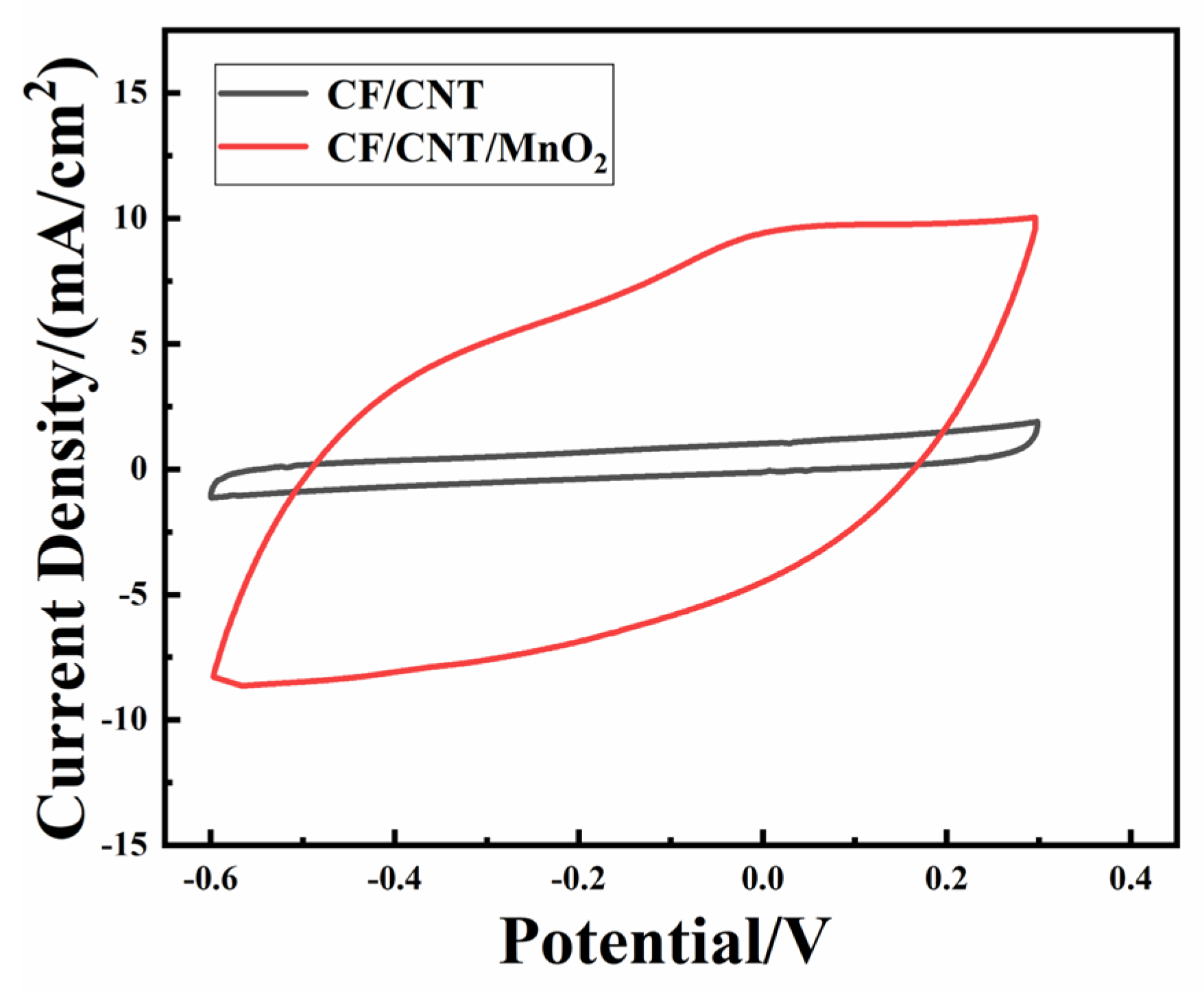
The CV was implemented with a scanning speed of 10 mV s
−1 as shown in
Figure 5. The area enclosed by cyclic voltammetry in applying the modified anode in the MFC was significantly larger than that of the control anode. This indicates that the anode attached to the CNT/MnO
2 had a large capacitance, which was proportional to the active surface area of the anode. This was due to the good biocompatibility of the CNT/MnO
2-modified anode. The large specific surface area of the CNT/MnO
2 composites was conducive to the attachment of microorganisms, and the doping of CNT improved the conductivity of the anode, enabling the rapid transfer of electrons from the biofilm to the anode.
The Laviron model [
28] was used to evaluate the electron transfer rate k of surface reactions to further explore the electron transfer dynamics of the CF/CNT/MnO
2 and CF/CNT anodes:
where α is the electron transfer coefficient, v is the scanning speed, E
0 is the standard potential, and Ep is the midpoint of the peak potential under a low sweep speed (EP
c: cathode; EP
a: anode). At a high scanning speed, E
p to lnv is a straight line, and the equation is as follows:
According to the above equation, the value k for the MnO2/CNT-modified anode was 0.47, while that of the CF/CNT anode was 0.18. This indicates that the rate-determining steps in the reduction and redox processes may be different. The electron transfer rate of the modified anode was faster. These results demonstrate that the MnO2/CNT composite increased the electron transfer rate.
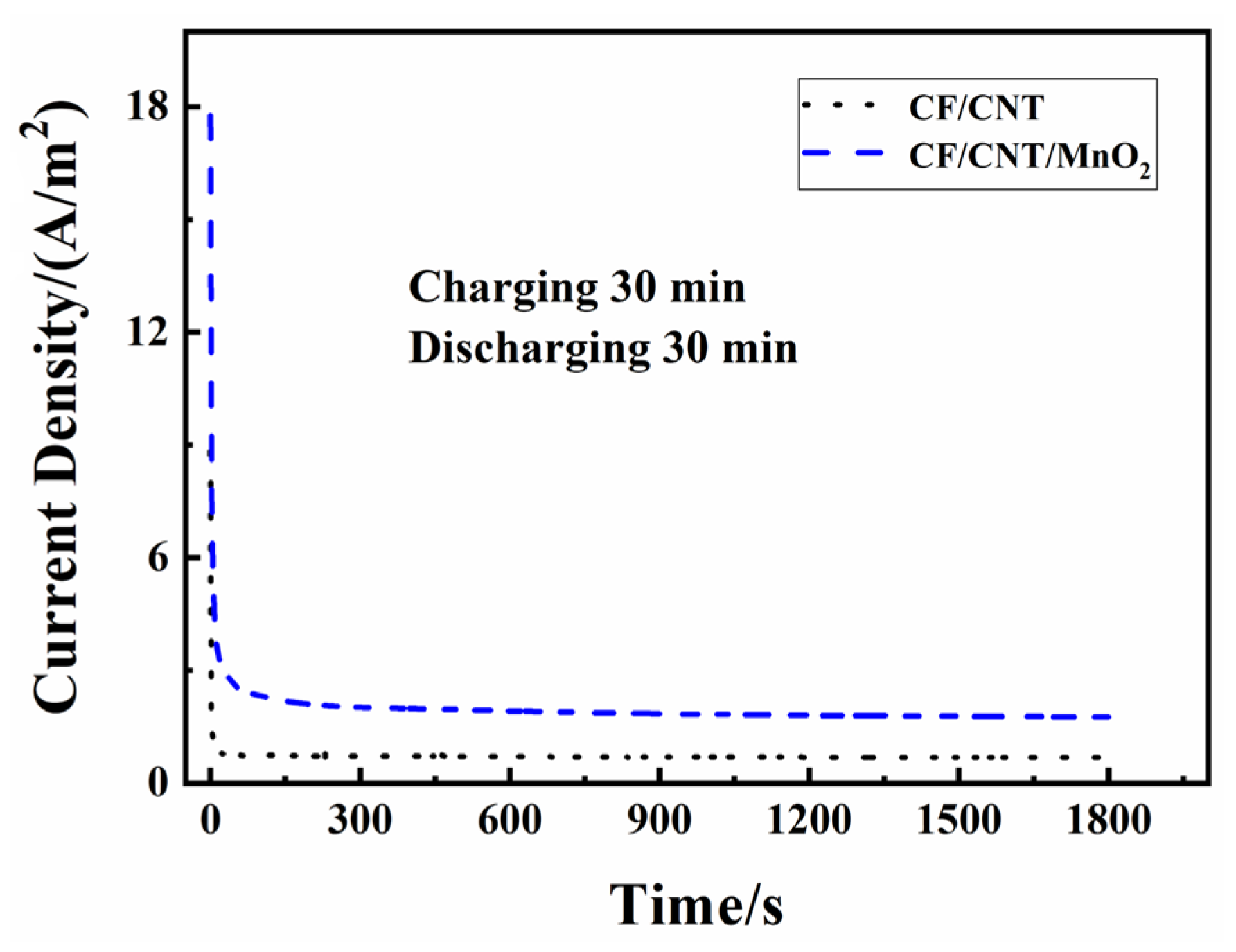
Figure 6 shows the discharge curves of two electrodes at 30 min. As shown in
Figure 6, both anodes had a peak current density value (i
h) at the initial discharge stage. The peak current density is related to the amount of stored electric quantity. The higher the current density, the more the electric quantity is stored in the charging phase. By comparing the i
h values of different anodes in each group of curves, it was found that the i
h of the CF/CNT/MnO
2 anode was larger than that of the CF/CNT anode. This shows that the energy storage capacity of the anode attached to the pseudo-capacitor and CNT composite material was much higher than that of the CF/CNT anode. After that, the current density gradually tended to have a stable current density (i
s). The greater the stable current, the better the anode energy storage capacity. Q
s is the stored electric quantity, and Q
t is the total electric quantity generated.
When the charge/discharge time was 30-30 min, the largest total charge Q
t (8777.1 C m
−2) observed with the CF/CNT/MnO
2 bioanode was 2.74 times higher than that of the control anode (3199.93 C m
−2). The charge stored in the CF/CNT/MnO
2 bioanode (1127.1 C m
−2) was 8.06 times higher than that of the CF/CNT anode (139.92 C m
−2). The specific values of stored charge, peak current density, and stationary current density are listed in
Table 2. It was shown that modification using the capacitive anode material could significantly improve the storage performance of the anode. In the charging and discharging process, the redox reaction occurs in the manganese dioxide pseudo-capacitor material.
When the electricity demand did not match electricity production, in the charging (open circuit) process, the electricity generated from the microbes could be firstly stored in the CNT/MnO2-modified bioanode; in the discharging (closed circuit) period, the two electron parts (produced electrons and stored electrons) were rapidly released simultaneously. More electrons could be transmitted from the anode to the cathode. Thus, the modified anode released much more charge than the unmodified anode. It was also demonstrated that CNT/MnO2-modified bioanode had a good ability to produce and store the charges.
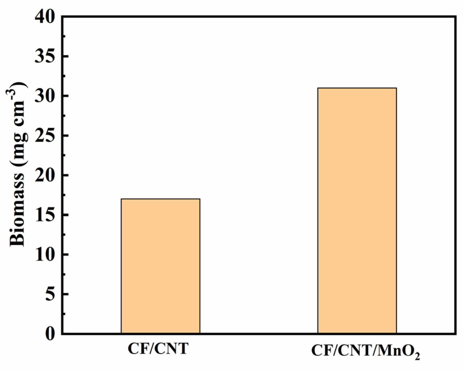
The basic building blocks of proteins are amino acids, which form peptide chains by condensation through dehydration. Proteins are biological macromolecules composed of one or more polypeptide chains. Determining their content is one of the most common and basic analytical methods in the microbial research field. The protein content of microorganisms loaded on different MFC anodes was examined in this paper for comparison.
The protein content of the two anodes is shown in
Figure 7. The protein contents of the two anodes were 17.12 and 31.98 mg cm
−3, respectively. The bioanodes loaded with the CNT/MnO
2 composite material showed a higher protein content than the CF/CNT anode. This indicates that the number of microorganisms on the anode loaded with the CNT/MnO
2 composite material was larger and the growth of microorganisms was more suitable, consistent with the MFC performance of the anode loaded with the CNT/MnO
2 composite material.


