Article

Hot Corrosion Behavior of Co–Al–W Superalloys with Si Additions

School of Materials Science and Engineering, Jiangsu University of Science and Technology, Zhenjiang 212003, China
*
Author to whom correspondence should be addressed.
Coatings 2023, 13(6), 1031; https://doi.org/10.3390/coatings13061031
Submission received: 28 April 2023 / Revised: 26 May 2023 / Accepted: 29 May 2023 / Published: 1 June 2023
(This article belongs to the Topic Properties of the Corroding Interface)

Abstract

:
The hot corrosion behavior of Co-9Al-9.5W-xSi (where x = 0%, 0.1%, 0.5%, at.%) alloys in a salt mixture at 900 °C was investigated. The effect of Si on hot corrosion resistance was examined using corrosion kinetics. The surface morphology of the corrosion products was explored via SEM with EDS and the phase constituents were examined using XRD. The results revealed that hot corrosion occurred as a combination of both sulfidation and oxidation behavior. With the increase in Si content, the hot corrosion resistance of the alloy was capable of remarkable advancement. Corrosion scales on the three Co-based alloys were mostly comprised of Co3O4, CoO, CoAl2O4, CoWO4, and Al2O3. The hot corrosion mechanism for the Co-based alloy in the presence of 75 wt.% Na2SO4 and 25 wt.% NaCl deposits were analyzed.

1. Introduction

Superalloys are a sort of metallic material which presents superior mechanical properties and thermal stability at elevated temperatures. They also possess good thermal corrosion resistance and fatigue resistance [1,2]. Hence, they are key materials in the manufacture of aero-engines, gas turbines electricity generators, steam turbines, and petrochemical components [3,4,5]. These alloys are usually based on Fe, Ni, and Co, which are stable not only at room temperature but also at elevated temperatures. Ni–based superalloys are widely applied in turbine blades, primarily because of their prominent ability to withstand high-temperature creep and fatigue, but also because their cost and availability are advantageous.
However, Co-based superalloys exhibit increasing prominence based on the following factors: their superior hot corrosion resistance, flatter stress-rupture/time parameter curves, and the relatively higher melting temperature of Co compared to Ni. However, due to the lack of a stable A3B type hardening phase, the traditional Co-based superalloy shows an inferior strength compared with Ni-based alloys. Sato et al. provided a pathway for a novel Co-based superalloy by reporting the relatively stable L12-Co3 (Al, W) phase in the Co–Al–W system. The superiority of traditional Co-based superalloys with regard to hot corrosion resistance most likely stems from the following reasons: high-level Cr content or low diffusion coefficient of S in the Co matrix. A large number of studies examined the hot corrosion properties of this newly developed alloy [6,7,8] and put forward a universal mechanism for high-temperature hot corrosion [9]. When compared against Ni-based superalloys, Co-based superalloys have excellent corrosion resistance, cobalt’s melting point is higher than that of nickel, and its service temperature is expected to exceed that of Ni-based superalloys [10]. Our results indicate that the Co–Al–W alloy has a higher incipient melting temperature as well as matchable mechanical properties [11,12,13]. Thus, this new type of γ′ precipitation-strengthened Co–Al–W superalloy was found to receive increasing attention. Kazuya claimed that the γ′ solvus temperature of Co-Ni-Al-W quaternary alloys is high when compared with Co–Al–W ternary alloys [14]. The γ′–γ two-phase regions in the Co–Ni–Al–W–Cr system can be extended with the addition of Ni [15].
As oxidation and hot corrosion are important factors in the length of superalloy service life, it is critical to investigate the oxidation and corrosion behaviors and the way they may be affected by alloying elements [16,17,18]. Hot corrosion is facilitated when fabricated components work in corrosive environments, such as exposure to SO2. Thus, hot corrosion is actually accelerated oxidation which is influenced by deposited salts [19]. When salt is placed at a higher temperature above its melting point, the oxide scales, such as Al2O3, Cr2O3, and SiO2, may be damaged by the molten salt mixture deposited on the coating surface, causing the spallation or dissolution of the oxide scales [19,20].
Numerous efforts were made to improve mechanical strength at high temperatures and to achieve better oxidation and hot corrosion resistance [21,22,23,24,25]. Gao found that the hot corrosion resistance of Co–Ni–Al–W–Cr alloys varied with variations in Ni content. Increasing the content of Ni resulted in the generation of more Ni3S2 and the aggravation of corrosion. Nevertheless, Ni can also lead to the formation of a protective layer of Al2O3, which can help protect the alloys [26]. Yan discovered that oxidation resistance could be slightly reduced by the addition of Ni [24]. Xu found that Ta and Nb raised the corrosion rate of Co-based superalloys because the severe segregation of Ta and Nb is prone to hot corrosion cracks [27]. Klein illustrated that Ta and Nb degrade the oxidation resistance of Co–Al–W–B alloy, while adding Cr and Si is beneficial to the oxidation resistance of the alloy [28]. Klein also claimed that Co–Ni-based alloys with 9 and 18 at.% Ni possessed similar oxidation resistance [3].
Up to now, few studies were conducted to investigate the hot corrosion properties of Co–Al–W-based alloys. The influence of Si content on this behavior was not systematically investigated. Two ways are often adopted to improve the hot corrosion behaviors of components working at elevated temperatures. The first way is to form a dense oxide scale which can provide a satisfying protective oxide. The addition of Si, an approach to adding alloying elements, is beneficial to developing a continuous compact oxide. The other way is to introduce a coating, such as MCrAlY and Al. If the Si-bearing alloy still cannot adopt an excellent resistance to heat corrosion, a coating is then necessary. Hence, the isothermal hot corrosion behavior of Co–Al–W superalloys with varied Si contents was examined in a mixture of 75% Na2SO4 + 25% NaCl (wt.%) molten salt at 900 °C, and the hot corrosion mechanism was explored.

2. Materials and Methods

High purity Co (99.9 wt.%), Al (99.9 wt.%), W (99.95 wt.%), and Si (99.99 wt.%) were employed to formulate the cast ingots of Co-9Al-9.5W-xSi, where x =  0, 0.1, 0.5, in at.%. The experimental alloys were melted by vacuum arc melting. Each ingot weighed about 80 g. The chamber was evacuated to 0.1 Pa and was, subsequently, filled with a high-purity argon atmosphere. This process was repeated before melting. The alloys were repeatedly melted 6 times to obtain a homogenous polycrystalline ingot. The nominal compositions of the alloys and actual compositions are listed in Table 1. The actual compositions were investigated by EDS analysis.
The ingots were sealed in vacuum quartz capsules and then solution-treated at 1230 °C for 8 h. Subsequent aging treatment was conducted at 900 °C for 72 h. Later, the samples were quickly quenched into ice water. Specimens with dimensions of 10 × 10 × 2 mm were cut from the ingots by a conventional wire electrode cutting. The microstructures of the alloys after heat treatment are given in Figure 1. The alloys showed a similar microstructure, which was primarily composed of γ and γ′ dual structures, as well as minor Co3W presented at the grain boundary. The specimens were polished down to 600-grit SiC paper, degreased in acetone, ultrasonically cleaned in ethanol, and then dried in the air prior to slat deposition.
We performed the hot corrosion test at 900 °C in static air. Before exposure, the samples were preheated on a heating table, followed by deposition with a saturated solution of 75% Na2SO4 + 25% NaCl (wt.%). The amount of deposition was controlled to 2.0 ± 0.2 mg/cm2. When the furnace reached a stable target temperature, the crucibles with samples were placed in the furnace. Hot corrosion tests were conducted at 900 °C at 2, 4, 8, 16, 32, and 64 h, respectively. Corrosion kinetics was measured by thermogravimetry. The weights of the specimens before and after corrosion tests were measured by an electro balance with a precision of 0.1 mg. The crystalline phases in the hot corrosion layers were determined by using X-ray diffraction (XRD-6000, Shimadzu, Kyoto, Japan) at a scanning speed of 4 °/min. A scanning electron microscope (Merlin Compact, Zeiss, Jena, Germany) was used to examine the surface morphologies of the specimens. An attached Energy Dispersive X-ray Spectroscopy (X-Max50, Oxford Instruments Inc., Abingdon, UK) was employed to determine the chemical composition of the phases and elemental distribution of the cross-section of the samples.

3. Results

3.1. Hot Corrosion Kinetics

Figure 2 reveals the corrosion kinetics of different Co–Al–W–xSi-based superalloys with a predeposition of 75 wt.% Na2SO4 + 25 wt.% NaCl at 900 °C, which is the mass gain per surface area of the samples as a function of the exposure time. As shown in Figure 2, the mass gain of all samples increased with the exposure time extension. The weight gain of tested samples increased as the exposure time extended up to 64 h. After 64 h of hot corrosion, the mass gains were 64.96 mg/cm2, 33.91 mg/cm2, and 37.19 mg/cm2, respectively. Thus, the molten mixture of 75 wt.% Na2SO4 + 25 wt.% NaCl quickened the corrosion rate of the three alloys. After 8 h, the corrosion rate of alloy A was about 1.5 times higher than that of alloy B and alloy C. Severe oxidation emerged during the testing process of specimen A. The corrosion products spalled with ease because of the stress deriving from the scale growth. Alloy A (0 Si) presents the highest mass gain of the three alloys. However, alloys B and C demonstrated a relatively slight rise in weight gain, which indicates that the use of Si can substantially enhance the hot corrosion resistance of Co–Al–W superalloys. A significant improvement can be seen in the 0.5 Si alloy.
A parabolic oxidation equation can be used to describe the hot corrosion process [29]
m S 2 = k P t + C
where m S is the specific mass gain (mass gain per unit area), k P represents the parabolic constant, t is the holding time, and C is a constant. The rate constant of the Si-free alloy was 1.81 × 10⁻⁸ g2cm−4s−1, but with the addition of minor contents of Si, the rate constant dropped to 4.95 × 10⁻⁹ g2cm−4s−1 for the 0.1 Si alloy and 4.39 × 10⁻⁹ g2cm−4s−1 for the 0.5 Si alloy. The oxidation rate constant of Co-5Al (wt.%, 10.7 in at.%) alloy was only between 3.3 × 10⁻⁹ g2cm−4s−1 and 4.2 × 10⁻⁹ g2cm−4s−1 at 900 °C [30]. The rate constant of Al71Co29 (at.%) alloy was 9.71 × 10⁻¹² g2cm−4s−1 for the first 15 h and 5.81 × 10⁻¹² g2cm−4s−1 for the second 15 h [29]. The Si-bearing alloy possessed a comparable oxidation rate with Co-5Al alloy but was much larger than that of the Al71Co29 alloy.

3.2. XRD Spectrum

Figure 3 reveals the XRD patterns of e alloys with varied Si content after hot corrosion for 2, 32, and 64 h at 900 °C. The corrosion products of alloys at these time intervals were similar, and the corrosion products mainly consisted of Co3O4 (PDF 43-1003), CoO (PDF 43-1004), Co2AlO4 (PDF38-0814), and CoWO4 (PDF 15-0867) oxides. Only the type of corrosion products in the outer layer and the sub-outer layer can be detected by XRD, so no sulfide was identified in the XRD patterns. The outer corrosion products were primarily oxides.

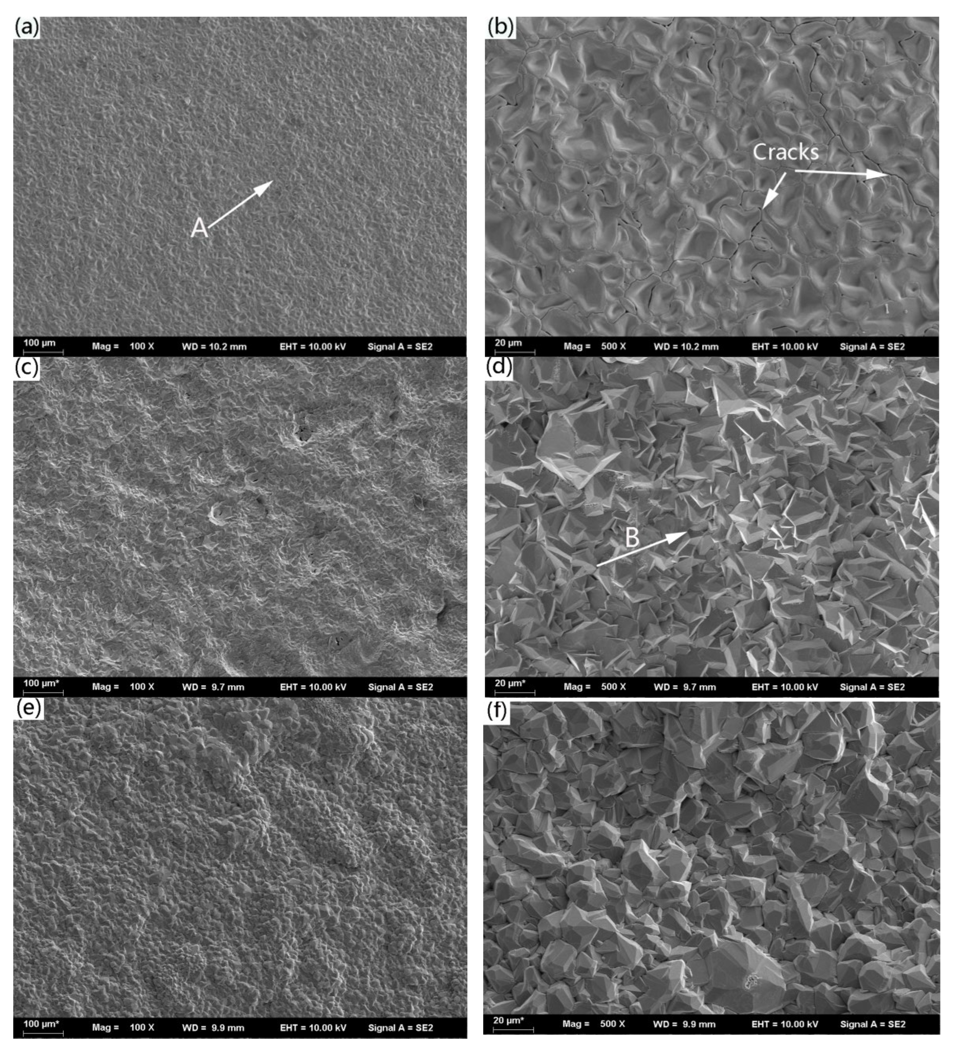
3.3. Surfae Morphologies

After corrosion, topographies of each sample for varied times are illustrated in Figure 4 and Figure 5. Figure 4b shows that some micro-cracks on the surface of alloy A appeared after hot corrosion for 2 h. By contrast, the surface of the corrosion scales on alloys B and C was relatively even and compact, which can be seen in Figure 4d,f. The components indicated by arrow A in Figure 4a are mainly Co and O. The content of the Co element was 45.05% (at.%) and the content of the O element was 54.95%. Combined with the analysis of our XRD results, the adherent outer layers on the surface were a mixture of Co3O4 and CoO, while no sulfide was detected. According to the EDS energy spectrum, the main components of the area indicated by arrow B in Figure 4d were Co and O, while the minor components were Na and W. The content of Co, O, Na, and W was 48.73%, 49.73%, 1.06%, and 0.48% receptively. The ratio of Co/O was greater than that of alloy A, which was close to the stoichiometric of CoO. This indicates that the primary component of the scale was CoO.
Figure 5a–c,e demonstrate that after 32 h of hot corrosion of the three alloys, some scale spallation was present on the surface. This may have resulted from the thermal stress concentration between the corrosion scales, which destroyed its shape. The cracks could serve as diffusion channels of oxygen, to accelerate the corrosion process of the substrate. According to EDS analysis, the rod-like product indicated by arrow A in Figure 5b constituted mostly O and a small quantity of Co, W, and S. The content of O, Co, W, and S elements was 71.23%, 12.79%, 15.28%, and 0.7%, respectively, which indicates that the rod-like product was CoWO4. The main components at the position indicated by arrow B were O and Co, as well as trace amounts of W. The content of the O element was 52.65%, and the content of the Co element was 46.42%. EDS measurements revealed that these products had compositions approaching the ideal composition of Co3O4 oxide. The rod-like product indicated by arrow C in Figure 5d was CoWO4, which was similar to the CoWO4 type oxide in Figure 5b.

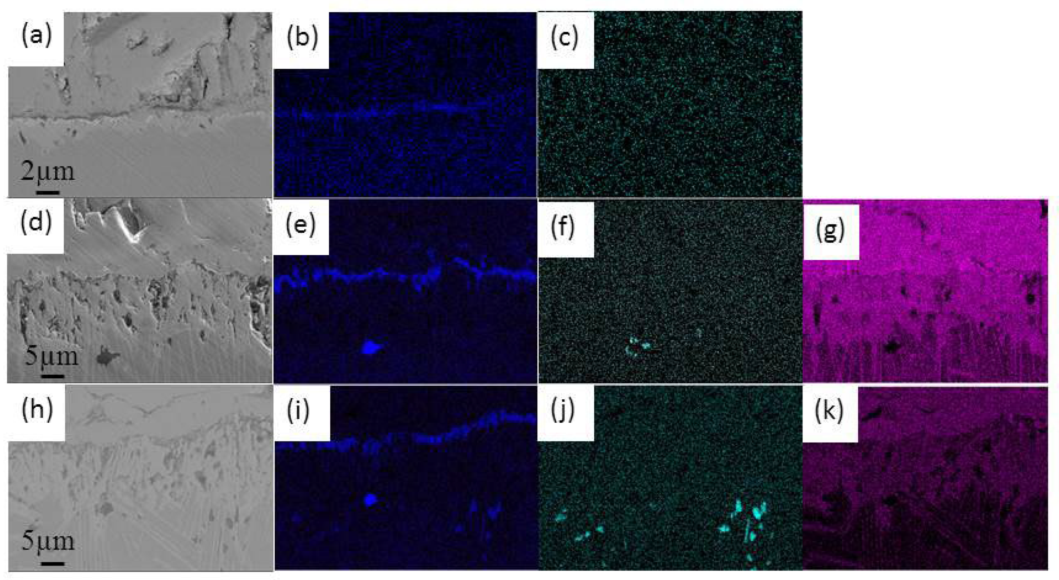
3.4. Cross-Section Morphologies

Figure 6 shows the cross-section morphologies of corrosion layers of the tested alloys after corrosion for 32 h. It illustrates that the thickness of the outer corrosion layer gradually decreased, and the density increased with the increment of Si content in the alloy. When this reached 0.5%, the outer corrosion layer became dense and continuous, so that it can inhibit the diffusion of O and S into the substrate and, thus, provided a better protective effect.
Through comparison of the three samples, we observed that the oxidation layer of Si-free alloy was by far the thickest. As shown in Figure 6a,d, the alloy exhibited four different layers. The outer layer was a mixture of CoO and Co3O4, which was porous. The second layer was a complex of CoWO4 and CoAl2O4, which was coarse and much more compact than the outer layer. The third layer was the Al-rich oxide layer. The inner layer was Co3W, whose Al content was depleted. The details of the Al-rich oxide layer and Co3W layer were revealed in Figure 6d–f.
The microphotographs and element mapping of the cross-section of the corrosion scale near the substrate of the three specimens are presented in Figure 7. Here, we observed that the intermediate transition layer was rich in Al, so a discontinuous layer of Al2O3 oxide film was developed in the base alloy. This can prevent the diffusion of O and S elements into the alloy. Depending on the oxidation temperature, whether the Al2O3 layer was continuous may be key to its protective role. Figure 7b shows that the Al-rich layer of Alloy A was thin and discrete and, thereby, it only played a limited role in protection. The layer of protective oxidation of Al2O3 was more significant in the 0.1 Si alloy than that of the Si-free alloy. The Al2O3 membrane can effectively prevent the diffusion of S and O into the substrate. The Al2O3 was relatively even and continuous, though still with some breakpoints. It can be observed from Figure 7h that the corrosion layer after the corrosion of C alloy for 32 h was separated into an outer and inner corrosion layer. The thickness of the outer corrosion layer was small, mainly rich in O, Si, and W elements, with a small part of the Co element. The intermediate layer was also a dense Al2O3 layer, which can help the alloy inhibit hot corrosion. In addition, from Figure 6c and d, we observed that the brighter part of the corrosion layer in the alloy contained primary O, Al, and W elements. This phase was stable at this temperature and was believed to reduce the detrimental effect of S, since the diffusion of S led to the reaction product of S and Al2O3. The internal corrosion layer of the alloy mainly contained Co, W, and Si elements. Although no SiO2 scale was observed in Figure 7, the Si showed an obvious outward diffusion trend and was rich in the oxide scale, outer layer, and intermediate layer, as seen in Figure 7g,k.

4. Discussion

In the present study, new types of Co-based superalloys with added Si were designed and their hot corrosion behaviors were investigated at 900 °C. The present investigation showed that the molten Na2SO4 + NaCl-induced hot corrosion was severe and contained notably thick and porous scale forms. Hot corrosion can be viewed as accelerated oxidation in the presence of a mixture of molten Na2SO4 and NaCl [17,31]. During the hot corrosion experiment, oxidation emerged first because of the reaction between the O and the substrate [32]. Usage of the molten salts initiated a rapid failure of the protective oxide layer. Alumina was formed by selective oxidation, and mixed salts reacted easily with oxides. Under these conditions, it was difficult for the oxide to develop a continuous protective oxide layer, and consequently, hot corrosion occurred. The molten Na2SO4 decomposed into O2 and S2 at 900 °C, and two equilibriums exist in the Na2SO4 [17].
Na2SO4 = Na2O + SO3
2SO3 = 3O2 + S2
The Na2SO4 can react with oxides formed under hot corrosion conditions. At the beginning stage of the hot corrosion, Co3O4, CoO, and Al2O3 formed due to the reaction between Co, Al, and O.
Al2O3 + Na2O = Al2O42− + 2Na+
CoO + Na2O = CoO22− + 2Na+
Co3O4 + Na2O = Co3O52−+2Na+
The ions produced (Al2O42−, CoO22−, and Co3O52−) may move from the molten salt/coating interface to the molten salt/air interface, where the basicity of the molten salt is low, and oxides can be reprecipitated by the decomposition of ions. This leads to the reprecipitation of the porous oxides. The process repeats itself, and the porous scale of Co3O4, CoO extends.
Al2O42− = Al2O3 + O2−
CoO22− = CoO + O2−
Co3O52− = Co3O4 + O2−
Johnson et al. examined the influence of NaCl and Na2SO4 on the high-temperature oxidation of Ni-based alloys [33]. The results demonstrate that Cl can advance the tendency of the scales to crack and spall during the initial oxidation. In the present study, NaCl in the mixed salts showed a similar impact [34,35,36,37,38,39].
Therefore, the presence of Na2SO4 + NaCl molten salts leads to the formation of the porous scale on three alloys. Because of the standard Gibbs free energy changes for the metallic oxides and sulfides at 1173 k are listed in the order of Al2O3 <  Cr2O3 <  Al2S3 <  CoO  <  CrS  <  NiO  <  Ni2S3 <  Co9S8 [40,41], Al would react preferentially with O2 penetrated through the scale to form Al2O3. This brings about the precipitation of Al2O3 in the alloy (internal oxidation zone), which is stable and dense [42]. Furthermore, 0.2% Ce plays a similar role in a Co–Al–W alloy [43]. The addition of Si may play one of several roles in the resistance to hot corrosion: firstly, it eases the formation of a continuous dense Al2O3; secondly, Si diffuses outward, reducing cracks and spalling of the oxide scale, as illustrated in Figure 4 and Figure 6.

5. Conclusions

The hot corrosion performance of a γ′ precipitation-strengthened Co–Al–W–XSi (where Si = 0, 0.1, 0.5) were studied with the predeposition of Na2SO4 + NaCl mixture at 900 °C. With the increase in Si content, the hot corrosion resistance of the alloy was substantially improved. The oxidation rate constant of Si-free alloy was 1.81 × 10 8   g 2 c m 4 s 1 , and when 0.5% Si was added into the alloy, the rate constant dropped to 4.39 × 10 9   g 2 c m 4 s 1 . The addition of Si promoted the formation of a continuous Al2O3 layer, which was beneficial for resistance to hot corrosion. In addition, the addition of Si may also reduce the intrusion of S and O by the formation of a stable oxide scale which is more resistant to crack and spallation.

Author Contributions

Conception, Y.Q. and S.C.; Materials preparation, Q.L.; Hot corrosion conduction, Y.W.; Analysis and writing, P.Z. All authors have read and agreed to the published version of the manuscript.

Funding

This research was funded by [National Natural Science Foundation of China], grant number [52275339] and [51471079].

Institutional Review Board Statement

Yanxin Qiao is an editorial board member for Coatings and was not involved in the editorial review or the decision to publish this article.

Informed Consent Statement

Not applicable.

Data Availability Statement

No extended data available.

Acknowledgments

We thank to Yigu Miao and William Bellamy for their language improvement.

Conflicts of Interest

The authors declare no conflict of interest.

References

  1. Ma, L.N.; Wang, T.Y.; Zhang, Z. Influence of Short-time Oxidation on Corrosion Properties of Directionally Solidified Superalloys with Different Orientations. J. Mater. Eng. 2016, 44, 78–87. [Google Scholar]
  2. Sung, J.K.; Hong, G.S.; Kim, W.Y.; Kim, M.S.; Chiba, A. Mechanical Property of Single Phase Co-Ni-Cr-Mo Based Superalloy Produced by Cold Working and Recrystallization Heat Treatment. Mater. Sci. Forum. 2004, 449–452, 573–576. [Google Scholar] [CrossRef]
  3. Klein, L.; Killian, M.S.; Virtanen, S. The effect of nickel and silicon addition on some oxidation properties of novel Co-based high temperature alloys. Corros. Sci. 2013, 69, 43–49. [Google Scholar] [CrossRef]
  4. Yang, L.; Bo, C.; Junwei, W.; Zhiping, W.; Wensheng, L. Corrosion Behavior of Cr, Fe and Ni Based Superalloy in Molten NaCl. Rare Metal. Mat. Eng. 2014, 43, 17–23. [Google Scholar] [CrossRef]
  5. Hongfang, M.; Ming, Z.; Yunmiao, Z. Corrosion behavior of two kinds of alloys in chloride molten salts. Mater. Rev. 2014, 28, 109–113. [Google Scholar]
  6. Huang, Q.Y.; Li, H.K. High Temperature Alloy; Metallurgical Industry Press: Beijing, China, 2000; pp. 100–133. [Google Scholar]
  7. Zhu, R.; Guo, M.J.; Zuo, Y. A study of the mechanism of internal sulfidation-internal oxidation during hot corrosion of Ni-base alloys. Oxid. Met. 1987, 27, 253–265. [Google Scholar]
  8. Kameswa, S.R. The role of NaCl in the hot-corrosion behavior of nimonicalloy 90. Oxid. Met. 1986, 26, 33–44. [Google Scholar] [CrossRef]
  9. Cui, H.; Zhang, J.; Murata, Y. Hot corrosion behavior of Ni-based superalloys with higher Cr contents—Part II. mechanism of hot corrosion behavior. J. Univ. Sci. Technol. B 1996, 3, 91. [Google Scholar]
  10. Klein, L.; Virtanen, S. Corrosion properties of novel γ′-strengthened Co-base superalloys. Corros. Sci. 2013, 66, 233–241. [Google Scholar] [CrossRef]
  11. Lass, E.A.; Williams, M.E.; Campbell, C.E.; Moon, K.W.; Kattner, U.R. γ′ Phase Stability and Phase Equilibrium in Ternary Co-Al-W at 900 °C. J. Phase Equilib. Diff. 2014, 35, 711–723. [Google Scholar] [CrossRef] [Green Version]
  12. Akanes, S.; Pollock, T.M. High-temperature strength and deformation of γ/γ′ two-phase Co-Al-W-base alloys. Acta Mater. 2008, 56, 1288–1297. [Google Scholar]
  13. Sato, J.; Tomori, T.; Oikawa, K. Cobalt-base high-temperature alloys. Science 2006, 90, 312. [Google Scholar] [CrossRef] [PubMed]
  14. Kazuya, S.; Toshihiro, O.; Jun, S.; Katsunari, O.; Ikuo, O.; Ryosuke, K.; Kiyohito, I. Phase equilibria and microstructure on γ′ phase in Co-Ni-Al-W system. Mater. Trans. 2008, 49, 1474–1479. [Google Scholar]
  15. Yang, S.Y.; Jiang, M.; Wang, L. Thermodynamic analysis of γ and γ′ phases in new-type co-based superalloy. J. Northeast. Univ. 2012, 33, 1274–1277. [Google Scholar]
  16. Young, D.J. High Temperature Oxidation and Corrosion of Metals; Elsevier: Amsterdam, The Netherlands, 2008. [Google Scholar]
  17. Goebel, J.A.; Pettit, F.S.; Goward, G.W. Mechanisms for the hot corrosion of nickel-base alloys. Metall. Trans. 1973, 4, 261–278. [Google Scholar] [CrossRef]
  18. Yan, H.Y.; Vorontsov, V.A.; Dye, D. Effect of alloying on the oxidation behaviour of Co-Al-W superalloys. Corros. Sci. 2014, 83, 382–395. [Google Scholar] [CrossRef]
  19. Lu, J.; Zhu, S.; Wang, F. High temperature corrosion behaviorof an AIP NiCoCrAlY coating modified by aluminizing. Surf. Coat. Technol. 2011, 205, 5053. [Google Scholar] [CrossRef]
  20. Jiang, S.M.; Peng, X.; Bao, Z.B.; Liu, S.C.; Wang, Q.M.; Gong, J.; Sun, C. Preparation and hot corrosion behaviour of a MCrAlY + AlSiY composite coating. Corros. Sci. 2008, 50, 3213. [Google Scholar] [CrossRef]
  21. Huang, D.; Qiao, Y.X.; Yang, L.L.; Wang, J.L.; Chen, M.H.; Zhu, S.L.; Wang, F.H. Effect of shot peening of substrate surface on cyclic oxidation behavior of sputtered nanocrystalline coating. Acta Metall. Sin. 2023, 59, 668–678. [Google Scholar]
  22. Suzuki, A.; Wu, F.; Murakami, H.; Imai, H. High temperature characteristics of Ir-Ta coated and aluminized Ni-base single crystal superalloys. Sci. Technol. Adv. Mater. 2004, 5, 555. [Google Scholar] [CrossRef] [Green Version]
  23. Wang, J.; Zhou, L.; Sheng, L.; Guo, J. The microstructure evolution and its effect on the mechanical properties of a hotcorrosion resistant Ni-based superalloy during long-term thermal exposure. Mater. Des. 2012, 39, 55. [Google Scholar] [CrossRef]
  24. Yan, H.Y.; Vorontsov, V.A.; Dye, D. Alloying effects in polycrystalline γ′, strengthened Co–Al–W base alloys. Intermetallics 2014, 48, 44–53. [Google Scholar] [CrossRef] [Green Version]
  25. Jiang, S.M.; Li, H.Q.; Ma, J.; Xu, C.; Gong, J.; Sun, C. High temperature corrosion behaviour of a gradient NiCoCrAlYSi coating II: Oxidation and hot corrosion. Corros. Sci. 2010, 52, 2316–2322. [Google Scholar] [CrossRef]
  26. Gao, B.; Wang, L.; Liu, Y.; Song, X.; Yang, S.-Y.; Yao, Z.-Y. Corrosion behavior of new type Co-based superalloys with different Ni contents. Corros. Rev. 2017, 35, 455–462. [Google Scholar] [CrossRef]
  27. Xu, Y.T.; Xia, T.D.; Yan, J.Q. Effect of alloying elements to hot corrosion behavior of novel Co-Al-W superalloy. J. Chin. Soc. Corros. Protect. 2010, 30, 457–464. [Google Scholar]
  28. Klein, L.; Bauer, A.; Neumeier, S.; Göken, M.; Virtanen, S. High temperature oxidation of γ/γ′-strengthened Co-base superalloys. Corros. Sci. 2011, 53, 2027–2034. [Google Scholar] [CrossRef]
  29. Šulhánek, P.; Drienovský, M.; Černičková, I.; Ďuriška, L.; Skaudžius, R.; Gerhátová, Ž.; Palcut, M. Oxidation of Al-Co Alloys at High Temperatures. Materials 2020, 13, 3152. [Google Scholar] [CrossRef] [PubMed]
  30. Irving, G.N.; Stringer, J.; Whittle, D.P. The high-temperature oxidation resistance of Co-Al alloys. Oxid. Met. 1975, 9, 427–440. [Google Scholar] [CrossRef]
  31. Eliaz, N.; Shemesh, G.; Latanision, R.M. Hot corrosion in gas turbine components. Eng. Fail. Anal. 2002, 9, 31–43. [Google Scholar] [CrossRef]
  32. Li, Y.Z.; Pyczakb, F.; Paulb, J.; Yaoa, Z. Oxidation behaviors of Co-Al-W-0.1B superalloys in a long-term isothermal exposure at 900 °C. J. Mater. Sci. Technol. 2018, 34, 2212–2217. [Google Scholar] [CrossRef]
  33. Johnson, J.B.; Nicholls, J.R.; Hurst, R.C.; Hancock, P. The mechanical properties of surface scales on nickel-base superalloys-II. Contaminant corrosion. Corros. Sci. 1978, 18, 543. [Google Scholar] [CrossRef]
  34. Sreedhara, G.; Raja, V.S. Hot corrosion of YSZ/Al2O3 dispersed NiCrAlYplasmasprayed coatings in Na2SO4–10 wt.%NaCl Melt. Corros. Sci. 2010, 52, 2592–2602. [Google Scholar] [CrossRef]
  35. Young, D.J.; Gleeson, B. Alloy phase transformations driven by high temperature corrosion processes. Corros. Sci. 2002, 44, 345–357. [Google Scholar] [CrossRef]
  36. Shinata, Y.; Nishi, Y. NaCl-induced accelerated oxidation of chromium. Oxid. Met. 1986, 26, 201–212. [Google Scholar] [CrossRef]
  37. Yao, Z.; Marek, M. NaCl-induced hot corrosion of a titanium aluminide alloy. Mater. Sci. Eng. A 1995, 192, 994–1000. [Google Scholar] [CrossRef]
  38. Li, Y.S. High Temperature Oxidation and Chlorination of Metal Materials; Dalian Institute of Science and Technology Press: Dalian, China, 2001. [Google Scholar]
  39. McKee, D.W.; Shore, D.A.; Lurthra, K.L. The effect of SO2 and NaCl on high temperature hot corrosion. J. Electrochem. Soc. 1978, 125, 411–419. [Google Scholar] [CrossRef]
  40. Ye, D.L.; Hu, J.H. Practical Inorganic Thermodynamic Data Manual Microtrainedinflux; Metallurgical Industry Press: Beijing, China, 2002. [Google Scholar]
  41. Barin, I. Thermochemical Data of Pure Substances; Science Press: Beijing, China, 2003; Volume 2. [Google Scholar]
  42. Forsik, S.A.J.; Rosas, A.O.P.; Wang, T.; Colombo, G.A.; Zhou, N.; Kernion, S.J.; Epler, M.E. High-Temperature Oxidation Behavior of a Novel Co-Base Superalloy. Metall. Mater. Trans. A 2018, 49A, 4058–4069. [Google Scholar] [CrossRef]
  43. Guan, Q.; Zhong, F.; Sha, J. Effect of Ce addition on hot corrosion behaviours of a cast γ’-strengthened Co–Al–W–Mo–Ta–B alloy at 800 °C. Prog. Nat. Sci.-Mater. 2022, 32, 463–471. [Google Scholar] [CrossRef]
Figure 1. Microstructure of each alloy after heat treatment: (a,c) Si-Free alloy; (b,d) 0.5 Si alloy.
Coatings 13 01031 g001
Figure 2. Corrosion kinetics of Co−Al−W–xSi-based superalloys in 75% Na2SO4 + 25% NaCl (wt.%) salts mixture at 900 °C.
Coatings 13 01031 g002
Figure 3. XRD spectrum of corrosion products obtained after hot corrosion in 75 wt.% Na2SO4 + 25 wt.% NaCl molten salts for (a) 2, (b) 32, (c) 64 h at 900 °C.
Coatings 13 01031 g003
Figure 4. SEM surface morphologies of the alloys exposed to 25 wt.% NaCl  +  75 wt.% Na2SO4 at 900 °C for varied times: (a,b) alloy A for 2 h; (c,d) alloy B for 2 h; (e,f) alloy C for 2 h.
Coatings 13 01031 g004
Figure 5. Topographies of the alloys exposed to 25 wt.% NaCl  +  75 wt.% Na2SO4 at 900 °C for different times: (a,b) alloy A for 32 h; (c,d) alloy B for 32 h; (e,f) alloy C for 32 h.
Coatings 13 01031 g005
Figure 6. Cross-section SEM micrograph of the three alloys after exposure to the mixture of Na2SO4 and NaCl melts at 900 °C for 32 h: (a) alloy A; (b) alloy B; (c) alloy C. Details of the Al-rich oxide layer and Co3W layer (df).
Coatings 13 01031 g006
Figure 7. BSE micrographs of (a) Si-free (d) 0.1 Si (h) 0.5 Si alloys and EDS mappings Al, S and Si: Al (b,e,i); S (c,f,j), and Si (g,k) Alloys exposed to 25 wt.% NaCl + 75 wt.% Na2SO4 at 900 °C for 32 h.
Coatings 13 01031 g007
Table 1. Nominal compositions and actual composition of experimental alloys (at.%).
HeatNominal Composition (at.%)Actual Compo Composition (at.%)
CoAlWSiCoAlWSi
ABal99.5081.778.919.32-
BBal99.50.181.878.859.28-
CBal99.50.581.598.819.270.33
Disclaimer/Publisher’s Note: The statements, opinions and data contained in all publications are solely those of the individual author(s) and contributor(s) and not of MDPI and/or the editor(s). MDPI and/or the editor(s) disclaim responsibility for any injury to people or property resulting from any ideas, methods, instructions or products referred to in the content.

