Article

Effect of Mechanical Vibration on Microstructure and Properties of Laser Cladding WC-Reinforced Nickel-Based Alloy Coatings

1
School of Mechanical Engineering, Xi’an University of Science and Technology, Xi’an 710054, China
2
State Key Laboratory of Solid Lubrication, Lanzhou Institute of Chemical Physics, Chinese Academy of Sciences, Lanzhou 730000, China
3
Shandong Laboratory of Yantai Advanced Materials and Green Manufacture, Yantai 264006, China
*
Author to whom correspondence should be addressed.
Coatings 2023, 13(5), 840; https://doi.org/10.3390/coatings13050840
Submission received: 20 March 2023 / Revised: 22 April 2023 / Accepted: 25 April 2023 / Published: 27 April 2023
(This article belongs to the Special Issue Laser Cladding Coatings: Microstructure, Properties, and Applications)

Abstract

:
Ni-WC composite coatings on 35CrMoV alloy surface were successfully prepared by mechanical vibration field-assisted laser cladding technology. Optical microscopy (OM) and scanning electron microscopy (SEM) were used to study the microstructure of the composite coatings without vibration and at different vibration frequencies; the phase composition of the cladding layer was studied by X-ray diffraction (XRD); and an energy dispersive spectrometer (EDS) was used for elemental plane scanning analysis. The grain growth trend under different convection directions was simulated. The wear resistance and mechanical properties of the composite coating were analyzed by friction and wear testing machine, three-dimensional surface profiler, and microhardness tester. The vibration field generated by the self-improved shaking table device is used to assist laser cladding. The effect of mechanical vibration on the quality of the cladding layer was studied. The results show that compared with the coating without mechanical vibration, an appropriate increase in vibration frequency contributes to the refinement of the grains. The original coarse dendrite structure becomes a fine needle-like structure, and the fine grain size gradually decreases. The application of vibration can improve the effect of grain refinement. The vibration makes the grain size distribution more uniform and the microhardness fluctuation of the cladding layer decreases. The experimental results show that mechanical vibration can improve the microstructure uniformity of the coating by selecting suitable vibration parameters. The average friction coefficient and wear width are reduced, and the microhardness is also increased.

1. Introduction

Laser cladding is a new laser processing technology with rapid melting and solidification. Through the rapid irradiation of its high-energy laser beam, the powder of the cladding layer is first melted into a molten pool in a short time and then rapidly solidified on the surface of the substrate so as to achieve a good metallurgical combination between the substrate and the cladding layer [1,2]. This is because the laser cladding technology can make the cheap plate and cladding powder form the metallurgical combination of high hardness, high wear resistance, corrosion resistance, and high-temperature oxidation resistance. At the same time, the thermal deformation of the matrix can be reduced, and the dilution rate of the cladding layer is low; therefore, it is widely used to improve the strengthening and repair of metal surfaces [3,4,5].
In recent years, Ni-based alloy powder has been widely used in the field of laser cladding because of its good wettability, abrasion resistance, corrosion resistance, impact resistance, fatigue resistance, and good self-lubrication under high-temperature conditions [6]. As a reinforcing particle in composite materials, WC has the advantages of high hardness and wear resistance and has good wettability between it and the Ni-based alloy powder. The uniform distribution of particles in the cladding layer can significantly improve the wear resistance of the cladding layer, which is an ideal hard phase material of the cladding layer [7,8,9].
In the laser cladding process, complex temperature fields will be generated during the rapid heating and cooling of the substrate surface. Under the influence of such factors, coarse columnar dendrites and uneven distribution of microstructure will often exist in the cladding layer, resulting in cracks or pores and other metallurgical defects [10,11,12]. The introduction of ultrasonic vibration in the laser cladding process has a significant effect on crack suppression and grain refinement. The introduction of ultrasonic vibration can reduce the porosity of the cladding layer, eliminate internal stress, and refine the microstructure, which plays an important role [13,14,15]. The ultrasonic vibration can increase the rate of liquid flow in the molten pool and make the elements evenly distributed, thus reducing the generation of various defects in the cladding layer. Increasing the flow speed of the liquid in the molten pool will also increase the cooling speed of the liquid itself, thus shortening the grain growth time in the cladding layer. In the process of crystal growth, the end and arm of the crystal are broken, and with the flow of liquid in the molten pool, the fine crystal structure formed is evenly distributed in the molten pool [16,17,18]. In addition, external electromagnetic fields have been introduced into laser cladding by some researchers at home and abroad, which has made some progress in reducing internal defects, reducing residual stress, refining and homogenizing microstructure, etc. [19,20,21,22]. The above studies mainly focus on the conditions of ultra-high frequency and high amplitude, and few kinds of literature report the influence of mechanical vibration on the laser cladding composite cladding layer under the conditions of low frequency and low amplitude. Therefore, this paper uses a mechanical vibration to assist the laser cladding process. The effect of mechanical vibration and convection on the quality of the laser cladding Ni-WC cladding layer of 35CrMoV alloy was studied.

2. Materials and Methods

2.1. Experimental Materials

In this experiment, 35CrMoV alloy plate is used as the base, and its composition is shown in Table 1. Before the experiment, the plates were cut to a predetermined size (100 × 60 × 10 mm3). The surface of the substrate was polished with a 60-mesh grinding wheel and cleaned with absolute ethanol to remove the oil stains on the surface of the substrate. Nickel powders with an average diameter of 50 to 100 μm were used as the coating matrix material; WC powder with an average diameter of 100 to 150 μm was used as the reinforcing particle of the coating. The Ni-WC mixed powder used in this experiment is the commercial powder purchased, and the specific composition and content of the mixed powder are provided by the merchant. The mass fraction of WC powder in Ni-WC mixed powder is 60%, and its mixture composition is shown in Table 2. The SEM morphology of the two powders is shown in Figure 1.

2.2. Test Equipment, Parameters, and Test Process

Laser cladding coating was obtained using BS-OF-3000-15-4L universal laser heat treatment equipment. Before coating, the powder mixture was thoroughly mixed with a planetary ball mill for 2 h until it was well mixed and then dried in a drying box at 80 °C for 2 h. Through experimental analysis and verification, the method of coaxial powder feeding is adopted. The technological parameters of laser cladding are as follows: power 2000 W, spot size 15 mm × 3 mm, scanning speed 120 mm/min, feeding rotary speed 300 r/min, lap rate 50%, high-purity argon gas flow rate 15 L/min.
In this experiment, a self-improved shaking table device is adopted, as shown in Figure 2. During the experiment, the vibration device was placed on the laser cladding workbench. The vibration frequency can be adjusted by adjusting the current. Through the previous experimental comparison, different vibration frequencies were determined in the formal cladding, which were, successively 0 Hz, 50 Hz, 150 Hz, and 300 Hz, and the amplitude was set as 1μm. The vibration was finally transmitted to the substrate in a direction perpendicular to the substrate. The clamp is used to fix the substrate on the vibration platform during cladding, and the vibration equipment shutdown delay is set for 60 s after laser cladding. After the experiment, the substrate was cut into samples with sizes of 15 × 10 × 10 mm3 and 10 × 10 × 10 mm3, respectively. The sample was ground and polished with different amounts of sandpaper and finally corroded with aqua regia for 4 s.

2.3. Sample Detect

The microstructure and structure of the coating were characterized by an optical microscope (OM). The microstructure and distribution of the coating were characterized by Nova Nano450 scanning electron microscopy (SEM) and the attached energy dispersive spectroscopy (EDS) analyzer. The phase changes of the coating surface were characterized by X-ray diffraction (XRD). The wear resistance of the sample surface was tested by the MFT-R4000 wear testing machine. The wear morphology of samples was characterized by Contour GT-K 3D optical profilometer. Vickers hardness measurements were performed on a through-thickness section normal to the deposition direction by means of a HMAS-D1000SZ microhardness tester. The load is 9.8 N, and the loading time is 15 s. The same horizontal plane of the cross-section of each sample was measured three times and then averaged.

3. Results and Discussion

3.1. Surface and Cross-Section Morphology of the Coating

Figure 3 shows the macroscopic and microscopic morphology of the cladding layer under different vibration frequencies in the previous experiment. In the preliminary experiment, laser cladding was carried out at different frequencies between 50 Hz and 300 Hz. It can be seen from the figure that the coating with good fusion quality can be successfully prepared on the surface of 35CrMoV alloy by using the mechanical vibration-assisted laser cladding technology. At the same time, the laser scanning track on the matrix surface can be clearly observed. It can be seen from the width of scanning lines that with the increase of vibration frequency, the width of the cladding layer also increases and is close to flat. When the vibration frequency increased from 50 Hz to 180 Hz, the cladding surface roughness gradually decreased. This is because the applied mechanical vibration frequency gradually increases to the resonance frequency of the substrate. When the vibration frequency increases from 185 Hz to 300 Hz, the surface roughness of the cladding layer gradually increases. This is because the frequency of the applied mechanical vibration slowly moves away from the resonant frequency of the substrate. It can be concluded that the appropriate vibration frequency can reach the resonance frequency of the substrate, which can better improve the quality of the cladding layer [14].
In order to analyze the influence of mechanical vibration power on the coating dilution rate, single-channel laser cladding tracks at vibration frequencies of 50, 80, 110, 150, 180, 220, 260, and 300 Hz were observed by optical microscopy. The typical cross-sectional profiles are shown in Figure 3. The measurement results show that with the increase of vibration frequency, the width of the cladding layer increases from 91.3 μm to 146.5 μm, while the depth of the cladding layer decreases from 31.3 μm to 7.3 μm. When mechanical vibration is applied, part of the energy generated by vibration will be absorbed by the atoms or molecules in the molten pool, and the irregular movement of the atoms or molecules that have absorbed energy will become more violent, eventually leading to the improvement of the fluidity in the molten pool. When the vibration frequency is low, the mobility of the molten pool is relatively poor, which leads to poor energy mobility in the molten pool. Therefore, the dilution rate of the coating is relatively high. With the increase of vibration frequency, the fluidity of the molten pool increases relatively. This results in good energy mobility of the molten pool and a relatively low dilution rate of the coating. Through analysis based on previous data, we finally decided to use laser cladding coatings with vibration frequencies of 0, 50, 150, and 300 Hz for further research on the structure and properties of the composite coatings.

3.2. Optical Microscope Analysis of Coating

Figure 4 shows the optical micrographs of the coating surface under different mechanical vibration frequencies. As can be seen from Figure 4, the coating surface is mainly composed of a large number of secondary dendrites, rod-like crystals, equiaxed crystals, and carbides. It can be observed from Figure 4a that when mechanical vibration is not applied, a large number of developed secondary dendrites and carbide particles with relatively large particle sizes exist on the coating surface. When the vibration frequency is 50 Hz, as shown in Figure 4b, a large number of developed secondary dendrites are broken and many broken dendrites are formed. This is because in the process of solidification and growth of dendrite in the molten pool, due to external mechanical vibration, the energy generated by vibration is absorbed by the crystal, and when the crystal grows to a certain length, it will be broken. At the same time, the larger size of carbide particles will be broken after absorbing the external energy. When the vibration frequency is 150 Hz, as shown in Figure 4c, a large amount of secondary dendrite is eventually broken to form a large amount of fine crystal. When the vibration frequency reaches 300 Hz, as shown in Figure 4d, some equiaxed crystal structures appear on the coating surface.
In addition, the mechanical vibration accelerates the flow of liquid in the molten pool, which makes the temperature of the liquid tend to be uniform, leading to a decrease in the temperature gradient. The temperature gradient is calculated using the following formula [23]:
G = 2 Π K ( T T 0 ) 2 η P
where K is the thermal conductivity of the material, T is the liquid temperature of the alloy, T0 is the preheating temperature of the substrate, η is the laser absorption coefficient, and P is the laser power. It can be seen from the formula that when the temperature gradient decreases under the action of mechanical vibration, the liquid metal temperature T decreases, and the initial substrate temperature T0 remains unchanged, leading to accelerated cooling of the substrate heat dissipation interface. Therefore, the composition and temperature tend to be uniform, which reduces the conditions for secondary dendrite formation and promotes the formation of fine crystals when supercooled.

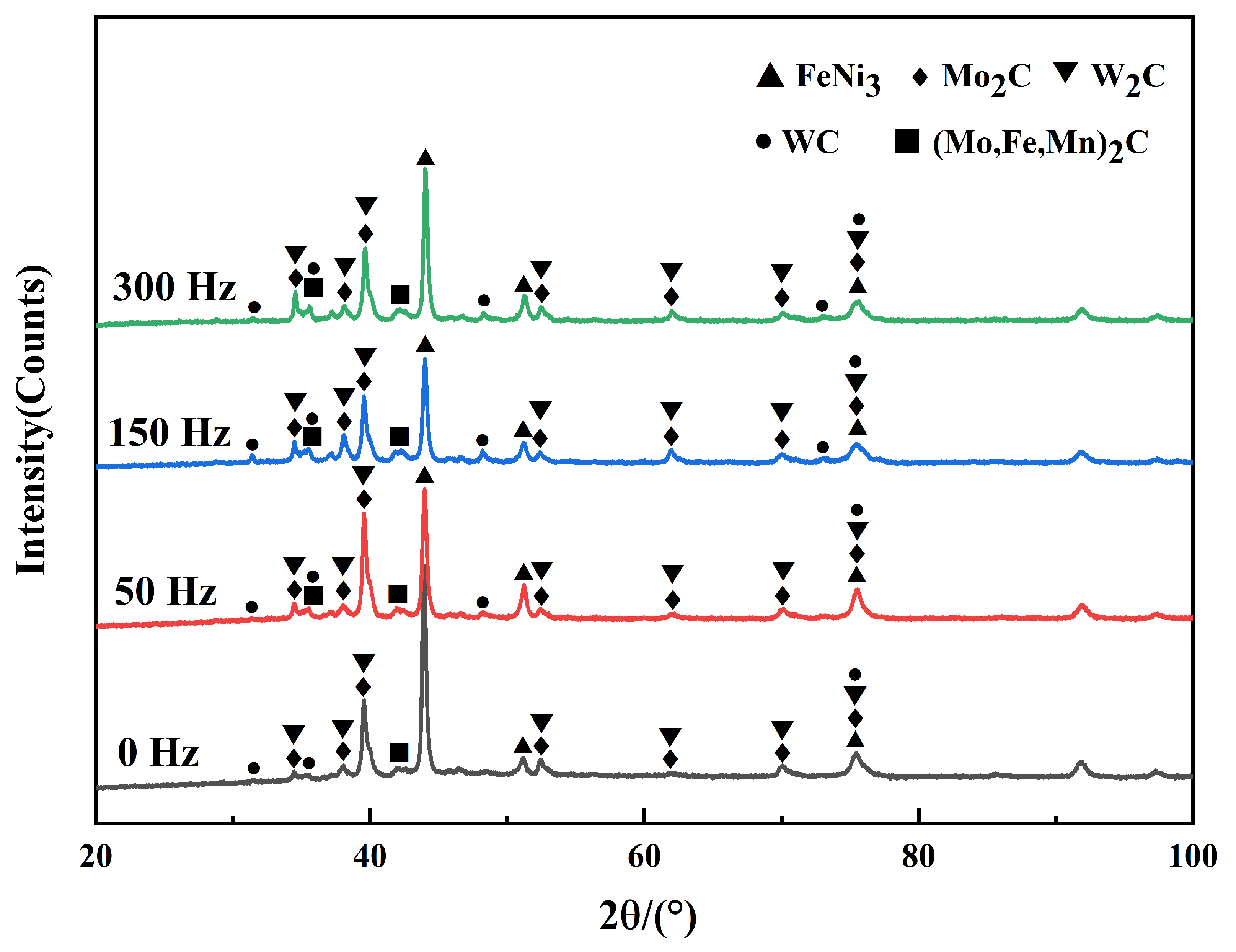
3.3. Microstructure and Phase Analysis of Coating

To further observe the morphology of the crystal, the microstructure of the coating was further analyzed by scanning electron microscopy. Figure 5 shows the microstructure of the coating surface under different vibration frequencies. It can be seen from Figure 5 that with the increase in vibration frequency, the microstructure refinement in the coating is very obvious. When no vibration is applied, as shown in Figure 5a, massive dendrites exist in the coating. This is because in the process of crystal growth without external conditions, the growth mode of the crystal is affected by its own. However, when mechanical vibration is applied, the crystal growth process is affected by the external field energy. As shown in Figure 5b, when the initially applied vibration is 50 Hz, the thick dendritic crystal will break when it grows to a certain length and form fine needle-like tissue due to the effect of vibration energy transfer during its growth. When the vibration frequency is 150 Hz, a large number of secondary dendrite arms will break. It can also be seen from the figure that some columnar crystals will also break under the condition of vibration, forming a large number of equiaxed crystals, and the grain refinement effect is the most obvious. When the vibration frequency reaches 300 Hz, as shown in Figure 5d, the coarse dendrites will be broken, but a few dendrites are not completely broken. Since mechanical vibrations are applied to speed up the flow of the molten pool, these broken crystals are distributed more evenly in the coating.
Figure 6 shows the evolution of carbide particle morphology in layers under different mechanical vibration frequencies. It can be seen from the figure that the degree of carbide fragmentation is different under different mechanical vibration frequencies. Figure 6a shows that no mechanical vibration is applied, and almost no carbide particles exist on the coating surface. There are some thick dendritic structures on its surface. This is because when mechanical vibration is not applied, the density of carbide particles in the molten pool is large, and a large number of carbide particles will sink to the bottom of the molten pool when the molten pool solidifies, which makes it difficult to find on the surface. However, when mechanical vibration is applied, because the direction of vibration is perpendicular to the processed surface of the substrate, the fluidity of the molten pool will be accelerated, so part of the carbide will solidify on the surface of the coating. When the vibration frequency is 50 Hz, as shown in Figure 6b, there are mainly some fishbone carbides on the surface of the coating. It can be seen from the figure that the boundary of the carbides is broken to a very small degree. When the vibration frequency is 150 Hz, as shown in Figure 6c, the carbide in the layer is broken to a great extent, and a large amount of broken triangular carbide is dissolved into the coating. When the vibration frequency reaches 300 Hz, as shown in Figure 6d, there are mainly some cylindrical carbides in the layer, and the fragmentation degree of carbides is relatively reduced. This may be because when the vibration frequency is 150 Hz, the vibration frequency reaches the resonance frequency of the matrix. This makes the carbide absorb most of the energy transferred by vibration at 150 Hz. Therefore, the degree of fragmentation is the largest.
The X-ray diffraction spectra of WC-Ni composite coatings at different vibration frequencies are shown in Figure 7. It can be seen from the atlas that there is no obvious change in the cladding phase with and without vibration, and the main components of the cladding phase are FeNi3, Mo2C, W2C, (Mo, Fe, Mn)2C, and a small amount of WC phase. The formation of these phases indicates that there is a good metallurgical combination between the matrix and the cladding layer, and the newly generated hard alloy phases are evenly distributed in the cladding layer, which improves the mechanical properties of the cladding layer. The W2C and MO2C produced in the cladding layer are the main reinforcement phases of the coating and Fe and Ni form FeNi3 solid solution in the cladding layer. It can be seen from the figure that the diffraction peak of WC is very weak, indicating that WC particles are almost all dissolved in the Ni-based alloy solvent. Compared to that without mechanical vibration, the intensity of the diffraction peak of FeNi3 solid solution decreases, indicating that mechanical vibration improves the solubility of FeNi3 solid solution in the cladding layer. Diffraction peaks of W2C, Mo2C, and (Mo, Fe, Mn)2C are enhanced, which is conducive to the formation of a stable microstructure [24]. The results show that the mechanical vibration causes the distribution of elements in the cladding layer to be more uniform, the grain size to be finer, and the grain integrity to be improved.
Figure 8 shows the schematic diagram of the laser cladding process assisted by mechanical vibration. The principle of mechanical vibration on microstructure refinement of composite coatings is revealed. When mechanical vibration is not applied, there are mainly some coarse dendrites in the coating. When mechanical vibration is applied in the process of laser cladding, the coarse crystals in the coating will be broken due to the convective effect of vibration (Figure 8a). The vibration promotes the fracture of the crystal, which, in turn, refines the grain size of the structure. During the solidification process of the molten pool, the convection effect caused by vibration produces a stirring effect on the molten pool, which is beneficial to the distribution of elements in the coating. At the same time, the effect of stirring greatly promotes the distribution of chemical components in the molten pool. Finally, the grain size is finer, and the distribution is more uniform. In Figure 8b, the change of crystal growth structure under the condition of external vibration is simulated. The angle between the convection direction and the transverse angle of the crystal are 0°, 30°, 45° and 60° from left to right, respectively. The morphology diagram of crystal step size at the same time, under the condition of vibration or its absence, is drawn by finite element analysis software. It is found that the applied mechanical vibration has a significant effect on the growth direction of the crystal. According to the theory of growth in backflow and no growth in oncoming flow, when vibration is applied, dendrites show strong right dendrite growth. This is because vibration can change the direction of convection in the molten pool, resulting in a different direction from that in the molten pool without vibration, thus changing the original growth path of dendrites. Therefore, mechanical vibration is an effective method to adjust dendrite morphology in the process of molten pool solidification.
In order to further analyze the distribution of elements in the coating by vibration frequency, EDS surface scanning was performed on the coating surface at different frequencies, and the results were shown in Figure 9. The main elements distributed on the crystal are Cr, Si, and W. The Fe and Ni elements are mainly distributed in the intergranular region. This shows that SiC, WC, and Cr3C2 are mainly distributed on the crystal. Fe-Ni solid solution is mainly distributed in the intercrystalline region. When no vibration is applied, there is a certain degree of segregation between the Cr element on the crystal and the Fe element in the intercrystalline region. The degree of segregation of Cr on the crystal and Fe elements in the intercrystalline region is slightly improved when the vibration frequency is 50 Hz. The degree of segregation of the Cr on the crystal and the Fe element in the intercrystalline is further weakened when the vibration frequency is 150 Hz and 300 Hz. The results show that mechanical vibration can improve the segregation degree of Cr and intercrystalline Fe elements and promote the uniform distribution of Si and W elements on the crystal and Ni elements in the intercrystalline region; however, it does not change the atomic concentration of the elements. The reason for this phenomenon is that when the mechanical vibration is continuously applied to the liquid pool, the energy generated by the vibration can break the dendritic structure and the thick coating carbide into fine grains, thus reducing the segregation degree of the elements. As the Stokes deposition rate decreases, the fluidity of the molten pool increases, which eventually weakens the segregation of the microstructure and causes the distribution of elements to become even [25]. According to the grain growth theory, the grain size is determined by the ratio between the nucleation rate and growth rate, and the larger the ratio, the smaller the grain size [26].

3.4. Wear Resistance and Hardness of the Coating

Figure 10a shows the friction coefficient curves of the coating under different mechanical vibration frequencies. Under the same experimental conditions, the material with a small friction coefficient has better wear resistance [27]. It can be observed from Figure 10a that with the increase of wear test time, the friction coefficient of the composite coating without mechanical vibration gradually increases from 0.4 to 0.6. When mechanical vibration is applied, the effect of vibration significantly reduces the average friction coefficient to 0.359. When the initially applied vibration frequency is 50 Hz, the friction coefficient of the coating is significantly reduced, which is lower than that without applied vibration. At the same time, it can be seen that when the vibration frequency is 150 Hz, the time to reach the running-in period is reduced, the friction coefficient of the coating is also the smallest, and the fluctuation of the curve is relatively stable, and the wear resistance is also improved. When the vibration frequency reaches 300 Hz, the friction coefficient is higher than that when the vibration frequency is 150 Hz. Figure 10b shows the average friction coefficient curve of the coating. The average friction coefficient was the lowest when the vibration frequency was 150 Hz (0.359). The results show that when the vibration frequency exceeds a certain value, the wear resistance of the composite coating will be reduced.
In order to further explore the wear resistance of the composite coating under different vibration frequencies, the 3D morphology of the wear marks was measured by a 3D optical profilometer. Figure 11 shows the three-dimensional morphology of the wear surface of Ni-WC composite coating under 5 N loads. By analyzing and comparing the width of the cross-section of the three-dimensional morphology of the composite coating under different vibration frequencies, the excellent degree of wear resistance of the composite coating is compared. As shown in Figure 11a, when no mechanical vibration is applied, the wear width of the wear surface reaches 172 μm. When the first applied vibration frequency is 50 Hz, as shown in Figure 11b, the wear width of the surface abrasion marks decreases to 161 μm. When the vibration frequency is 150 Hz, as shown in Figure 11c, the wear width of the surface abrasion marks decreases to 115 μm, and the wear width reaches the minimum at this time, indicating that the wear resistance of the composite coating reaches the best at the vibration frequency of about 150 Hz. As the vibration frequency continued to increase, when the vibration frequency reached 300 Hz, as shown in Figure 11d, the wear width of the surface increased to 130 μm. This further indicates that when the vibration frequency exceeds a certain value, the wear resistance of the coating will not increase but decrease.
Figure 12a shows the microhardness curve of the coating surface under different vibration frequencies. It can be inferred that the microhardness of the coating increases with the increase in vibration frequency. When the vibration frequency is 0, 50, 150, and 300 Hz, the average microhardness of the coating is 751.71, 790.45, 862.02, and 811.17 HV1 (Figure 12b). It can be seen from the fluctuation of the figure line. The average microhardness of the coating first increases and then decreases with the increase of vibration frequency. The microhardness of the matrix is about 341.4 HV1, and the microhardness of the composite coating is between 600 and 910 HV1. When the vibration frequency is 150 Hz, the curve fluctuation is relatively stable, and the average microhardness is the highest. At this time, the microhardness of the composite coating reaches 901.5 HV1, which is 2.6 times the hardness of the matrix. With the increase of vibration frequency, the average microhardness of the coating first increases and then decreases. It is speculated that the resonance frequency of the matrix may be reached during this process. When the resonance frequency of the matrix is reached, the energy absorbed by the molten pool is the maximum. The flow of the molten pool is greatly accelerated. The tissue is more evenly distributed. The uniformity of the tissue distribution has an important effect on the microhardness of the coating. The more homogeneous the tissue is, the higher the microhardness is. Compared with the matrix, the average microhardness of the composite coating is increased by 15% after the application of vibration. This fully indicates that the application of mechanical vibration can significantly improve the microhardness of the composite coating, indicating that the application of mechanical vibration is an effective method to enhance the mechanical properties of the laser cladding composite coating.

4. Conclusions

(1)
WC-reinforced Ni-base composite coating was prepared on the surface of 35CrMoV alloy by applying a mechanical vibration field, and the dilution rate of the coating decreased with the increase of vibration frequency. With the increase in vibration frequency, the width of the molten pool increases and the depth decreases. Mechanical vibration promotes the fluidity of the molten pool;
(2)
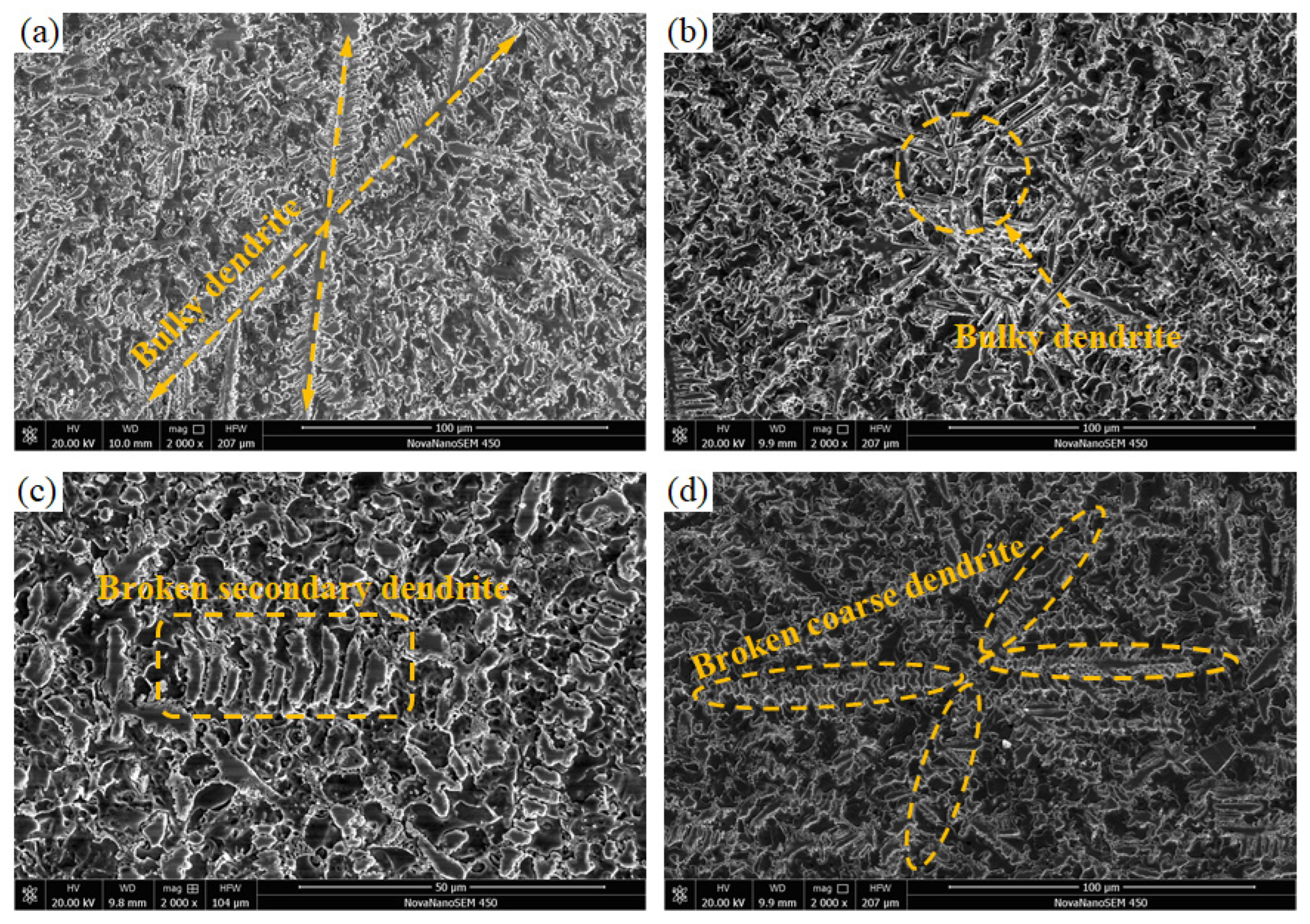
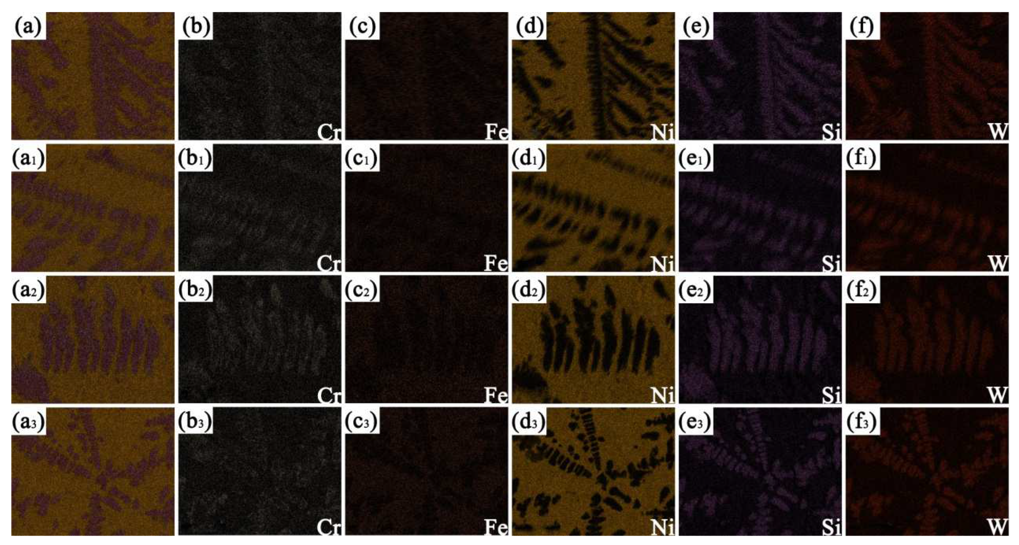
The application of mechanical vibration can cause the coarse grain in the coating to be broken, and the grain size can be reduced at the same time. The grain distribution in the layer is more uniform, and the element distribution is even. In the process of laser cladding, mechanical vibration can effectively improve the cladding effect and improve the quality of the coating;
(3)
When the vibration frequency is 150 Hz, the microhardness of the composite coating reaches 901.5 HV1, which is 2.6 times that of the matrix. The average microhardness of the composite coating increased by 15% after external vibration;
(4)
Under the 150 Hz vibration frequency, the average friction coefficient of the composite coating decreases from 0.544 to 0.359, which is 34% lower than that of the non-vibration composite coating. The wear width is shortened from 172 μm to 115 μm, the wear resistance is remarkable, and the mechanical properties are excellent.

Author Contributions

Conceptualization, Z.G. (Zhongtang Gao) and Z.G. (Zhiming Gao); data Analysis and writing, C.R.; simulation, L.D.; investigation, J.L.; supervision, Z.Q. and C.Z. All authors have read and agreed to the published version of the manuscript.

Funding

NSFC (51804251: 52104384); Science Fund of Shandong Laboratory of Yantai Advanced Materials and Green Manufacturing (AMGM2021F04); Planning project of Xi’an Science and Technology (21XJZZ0041); China Postdoctoral Science Foundation (2020M683675XB); NSF of Shaanxi Provincial Department of Education (21JK0761); Key Research and Development Program of Shaanxi (2023-YBGY-343).

Institutional Review Board Statement

Not applicable.

Informed Consent Statement

Not applicable.

Data Availability Statement

Not applicable.

Conflicts of Interest

The authors declare no conflict of interest.

References

  1. Lv, J.; Zhou, J.; Zhang, T.; Meng, X.; Li, P.; Huang, S. Microstructure and Wear Properties of IN718/WC Composite Coating Fabricated by Ultrasonic Vibration-Assisted Laser Cladding. Coatings 2022, 12, 412. [Google Scholar] [CrossRef]
  2. Zhuang, D.-D.; Du, B.; Zhang, S.-H.; Tao, W.-W.; Wang, Q.; Shen, H.-B. Effect and action mechanism of ultrasonic assistance on microstructure and mechanical performance of laser cladding 316L stainless steel coating. Surf. Coat. Technol. 2022, 433, 128122. [Google Scholar] [CrossRef]
  3. Sun, F.; Cai, K.; Li, X.; Pang, M. Research on Laser Cladding Co-Based Alloy on the Surface of Vermicular Graphite Cast Iron. Coatings 2021, 11, 1241. [Google Scholar] [CrossRef]
  4. Wang, K.; Du, D.; Liu, G.; Chang, B.; Hong, Y. Microstructure and properties of WC reinforced Ni-based composite coatings with Y2O3 addition on titanium alloy by laser cladding. Sci. Technol. Weld. Join. 2019, 24, 517–524. [Google Scholar] [CrossRef]
  5. Weng, Z.; Wang, A.; Wu, X.; Wang, Y.; Yang, Z. Wear resistance of diode laser-clad Ni/WC composite coatings at different temperatures. Surf. Coat. Technol. 2016, 304, 283–292. [Google Scholar] [CrossRef]
  6. Ma, Q.; Li, Y.; Wang, J.; Liu, K. Microstructure evolution and growth control of ceramic particles in wide-band laser clad Ni60/WC composite coatings. Mater. Desing 2016, 92, 897–905. [Google Scholar]
  7. Guo, C.; Chen, J.; Zhou, J.; Zhao, J.; Wang, L.; Yu, Y.; Zhou, H. Effects of WC–Ni content on microstructure and wear resistance of laser cladding Ni-based alloys coating. Surf. Coat. Technol. 2012, 206, 2064–2071. [Google Scholar] [CrossRef]
  8. Zhang, P.; Pang, Y.; Yu, M. Effects of WC Particle Types on the Microstructures and Properties of WC-Reinforced Ni60 Composite Coatings Produced by Laser Cladding. Metals 2019, 9, 583. [Google Scholar] [CrossRef] [Green Version]
  9. St-Georges, L. Development and characterization of composite Ni–Cr + WC laser cladding. Wear 2007, 263, 562–566. [Google Scholar] [CrossRef]
  10. Xie, S.; Li, R.; Yuan, T.; Chen, C.; Zhou, K.; Song, B.; Shi, Y. Laser cladding assisted by friction stir processing for preparation of deformed crack-free Ni-Cr-Fe coating with nanostructure. Opt. Laser Technol. 2018, 99, 374–381. [Google Scholar] [CrossRef]
  11. Zhao, Y.; Wu, M.; Hou, J.; Chen, Y.; Zhang, C.; Cheng, J.; Li, R. Microstructure and high temperature properties of laser cladded WTaNbMo refractory high entropy alloy coating assisted with ultrasound vibration. J. Alloy. Compd. 2022, 920, 165888. [Google Scholar] [CrossRef]
  12. VOcelík, V.; de Oliveira, U.; de Boer, M.; de Hosson, J. Thick Co-based coating on cast iron by side laser cladding: Analysis of processing conditions and coating properties. Surf. Coat. Technol. 2007, 201, 5875–5883. [Google Scholar] [CrossRef] [Green Version]
  13. Xu, J.; Zhou, J.; Tan, W.; Huang, S.; Wang, S.; He, W. Ultrasonic vibration on wear property of laser cladding Fe-based coating. Surf. Eng. 2020, 36, 1261–1269. [Google Scholar] [CrossRef]
  14. Li, C.; Zhang, Q.; Wang, F.; Deng, P.; Lu, Q.; Zhang, Y.; Li, S.; Ma, P.; Li, W.; Wang, Y. Microstructure and wear behaviors of WC-Ni coatings fabricated by laser cladding under high frequency micro-vibration. Appl. Surf. Sci. 2019, 485, 513–519. [Google Scholar] [CrossRef]
  15. Li, C.; Li, S.; Zeng, M.; Sun, S.; Wang, F.; Wang, Y. Effect of high-frequency micro-vibration on microstructure and properties of laser cladding aluminum coatings. Int. J. Adv. Manuf. Technol. 2019, 103, 1633–1642. [Google Scholar] [CrossRef]
  16. Wang, F.; Li, C.; Sun, S.; Zeng, M.; Liu, C.; Lu, Q.; Wang, Y. Al2O3/TiO2-Ni-WC Composite Coatings Designed for Enhanced Wear Performance by Laser Cladding Under High-Frequency Micro-Vibration. Jom 2020, 72, 4060–4068. [Google Scholar] [CrossRef]
  17. Gao, Z.; Ren, H.; Geng, H.; Yu, Y.; Gao, Z.; Zhang, C. Effect of CeO2 on Microstructure and Wear Property of Laser Cladding Ni-Based Coatings Fabricated on 35CrMoV Steel. J. Mater. Eng. Perform. 2022, 31, 9534–9543. [Google Scholar] [CrossRef]
  18. Liu, Q.; Zang, Y.; Song, Y.; Qi, F.; Zhai, Q. Influence of ultrasonic vibration on mechanical properties and microstructure of 1Cr18Ni9Ti stainless steel. Mater. Design 2007, 28, 1949–1952. [Google Scholar]
  19. Wang, D.S.; Zhu, Y.Y.; Qu, G.; Zhou, X.H. Influential Effects of Follow-up Feed Pulse Current on a Laser Clad Ni-based Alloy Coating. Lasers Eng. 2022, 52, 151–167. [Google Scholar]
  20. Zhai, L.; Wang, Q.; Zhang, J.; Ban, C. Effect of alternating current electric field on microstructure and properties of laser cladding Ni-Cr-B-Si coating. Ceram. Int. 2019, 45, 16873–16879. [Google Scholar] [CrossRef]
  21. Zhang, T.; Li, P.; Zhou, J.; Wang, C.; Meng, X.; Huang, S. Microstructure evolution of laser cladding Inconel 718 assisted hybrid ultrasonic-electromagnetic field. Mater. Lett. 2021, 289, 1873–4979. [Google Scholar] [CrossRef]
  22. Wang, Y.; Shi, H.; Hao, X.; Liu, H.; Zhang, X. Microstructure and Wear Resistance of Fe60 Laser Cladding Coating Assisted by Steady Magnetic Field-Mechanical Vibration Coupling Field. Coatings 2022, 12, 751. [Google Scholar] [CrossRef]
  23. Zhou, S.; Xiong, Z.; Dai, X.; Liu, J.; Zhang, T.; Wang, C. Microstructure and oxidation resistance of cryomilled NiCrAlY coating by laser induction hybrid rapid cladding. Surf. Coat. Technol. 2014, 258, 943–949. [Google Scholar] [CrossRef]
  24. Nurminen, J.; NaKKi, J.; Vuoristo, P. Microstructure and properties of hard and wear resistant MMC coatings deposited by laser cladding. Int. J. Refract. Metals Hard Mater. 2009, 27, 472–478. [Google Scholar] [CrossRef]
  25. Gao, Z.; Geng, H.; Qiao, Z.; Sun, B.; Gao, Z.; Zhang, C. In situ TiBX/TiXNiY/TiC reinforced Ni60 composites by laser cladding and its effect on the tribological properties. Ceram. Int. 2023, 49, 6409–6418. [Google Scholar] [CrossRef]
  26. Shen, Y.J.; Li, X.F.; Chen, X.Y. Effect of Ultrasonic Power on microstructure and properties of Laser cladding Fe-Cr-V Coatings. Trans. China Weld. Inst. 2017, 38, 74–78+132. [Google Scholar]
  27. Gao, Z.; Zhang, S.; Ren, C.; Yu, Y.; Gao, Z.; Zhang, C. Effect of Rare-Earth La2O3 on Tribological Properties of Laser Cladding Nickel-Based Coatings on 35CrMoV Alloy Steel. J. Mater. Eng. Perform. 2023. [Google Scholar] [CrossRef]
Figure 1. SEM morphology of power: (a) WC; (b) Ni.
Coatings 13 00840 g001
Figure 2. Laser cladding equipment and vibration equipment.
Coatings 13 00840 g002
Figure 3. Morphology of cladding layer and typical cladding profile under different vibration frequencies.
Coatings 13 00840 g003
Figure 4. Optical micrographs of the coating surface at different vibration frequencies: (a) 0 Hz; (b) 50 Hz; (c) 150 Hz; (d) 300 Hz.
Coatings 13 00840 g004
Figure 5. SEM diagram of crystal morphology evolution: (a) 0 Hz; (b) 50 Hz; (c) 150 Hz; (d) 300 Hz.
Coatings 13 00840 g005
Figure 6. SEM diagram of carbide morphology evolution: (a) 0 Hz; (b) 50 Hz; (c) 150 Hz; (d) 300 Hz.
Coatings 13 00840 g006
Figure 7. XRD patterns of the coating at different vibration frequencies.
Coatings 13 00840 g007
Figure 8. Schematic diagram and simulation of dendrite evolution under vibrational convection: (a) schematic diagram of dendrite evolution; (b) simulation results of dendrite evolution under different convection directions.
Coatings 13 00840 g008
Figure 9. Scanning results of coating surface at different vibration frequencies: (af) 0 Hz; (a1f1) 50 Hz; (a2f2) 150 Hz; (a3f3) 300 Hz.
Coatings 13 00840 g009
Figure 10. Friction coefficient curves of the coating at different vibration frequencies: (a) coefficient of friction; (b) average friction coefficient.
Coatings 13 00840 g010
Figure 11. Three-dimensional morphology of coating wear at different vibration frequencies: (a) 0 Hz; (b) 50 Hz; (c) 150 Hz; (d) 300 Hz.
Coatings 13 00840 g011
Figure 12. Microhardness curves of coating sections under different vibration frequencies: (a) microhardness; (b) average microhardness.
Coatings 13 00840 g012
Table 1. Chemical composition of 35CrMoV alloy plate (wt.%).
ElementsCSiMnCrMoVPSCuNi
35CrMoV0.30–0.380.17–0.370.40–0.700.80–1.100.15–0.250.10–0.20≤0.035≤0.035≤0.030≤0.030
Table 2. Chemical composition of Ni-WC (wt.%).
ElementsNiWCCrSiFe
Ni-WCBal57.32.452.361.110.12
Disclaimer/Publisher’s Note: The statements, opinions and data contained in all publications are solely those of the individual author(s) and contributor(s) and not of MDPI and/or the editor(s). MDPI and/or the editor(s) disclaim responsibility for any injury to people or property resulting from any ideas, methods, instructions or products referred to in the content.

