Article

Impact Resistance of CVD Multi-Coatings with Designed Layers

1
Institute of Manufacturing Engineering, Huaqiao University, Xiamen 361021, China
2
College of Marine Equipment and Mechanical Engineering, Jimei University, Xiamen 361021, China
3
Zhejiang Xinxing Tools Co., Ltd., Jiaxing 314300, China
4
Dongfang Turbine Co., Ltd., Deyang 618000, China
5
College of Mechanical Engineering and Automation, Huaqiao University, Xiamen 361021, China
*
Authors to whom correspondence should be addressed.
Coatings 2023, 13(5), 815; https://doi.org/10.3390/coatings13050815
Submission received: 30 March 2023 / Revised: 20 April 2023 / Accepted: 21 April 2023 / Published: 22 April 2023
(This article belongs to the Special Issue Recent Advances in the Development of Thin Films)

Abstract

:
Coated cutting tools are widely used in the manufacturing industry due to their excellent properties of high heat resistance, high hardness, and low friction. However, the milling process is a dynamic process, so the coatings of milling tools suffer severe cyclic impact loads. Impact resistance is important for the life of milling tools. Multi-coatings with different layer thickness may influence their impact resistance, but few studies focus on this topic. In this study, CVD coating with a structure of TiN layer, Al2O3 layer, and TiCN layer was selected as the research objective. Four different CVD coatings with different layer thicknesses were designed and prepared. The impact resistance test method was proposed to simulate the impact due to cut-in during down the milling process. We obtained the load by setting an impact depth of 25/30/35 µm, recording the impact force during the impact process, and calculating the contact stress; it was found that, at the impact depth of 25/30/35 µm, the download loads were around 9/11/13 N, while the contact stresses were all around 1 GPa. The failure morphology of the coating surface was investigated after the impact process. By comparing the contact stress and the surface morphology of the designed coatings, the impact resistance of four kinds of designed CVD coatings were evaluated. Experiments have shown that an increase in coating thickness and total coating thickness reduces impact resistance by about 10%. The impact resistance of coating samples without a TiN surface layer also decreased by about 10%. When the surface layer of TiN was thinner than 1 µm, the surface layer of TiN was prone to chipping and peeling off. Decreasing the thickness of the middle layer of Al2O3 and increasing the thickness of the inner layer of TiCN obviously lowered the impact resistance.

1. Introduction

Coated cutting tools have been widely used in the manufacturing industry, where the parts require high geometrical precision, machining efficiency, and surface quality. Tool coatings have demonstrated excellent static properties such as heat resistance [1], hardness [2], and anti-adhesion [3]. However, cutting is a dynamic process that involves complex stress conditions applied on the tool coatings. Therefore, coatings with excellent static properties may not perform well when suffering cyclic and impact loads [4]. The coating surface of cutting tools suffers cyclic fatigue impacts with a frequency ranging from 1 to 1 kHz due to the contact and separation of the tool and workpiece during milling, which can lead to coating damage [5], while the generation of serrated chips during the turning process of difficult-to-machine materials can result in high-frequency cyclic fatigue impacts above 1 kHz, leading to coating chipping. The response of the coating to these cyclic fatigue impacts determines its cutting performance; therefore, the fatigue resistance of coating tools is regarded as an important index to evaluate the performance of coating tools [6].
However, cutting processes contain friction processes, heating processes, deformation processes, as well as impact processes [7], so the coated tool’s wear after cutting experiments may not reflect the fatigue impact resistance of cutting tool coatings individually [8]. Impact tests are an effective method to evaluate the performance of cutting tool coatings [9].
Lamri et al. [10,11] utilized electromagnets to drive a rigid indenter to repeatedly impact the sample material with constant acceleration. The initial position of the indenter was adjusted to control the impact velocity, which was detected by a laser displacement sensor. The impact frequency of this impact test device was 10 Hz, and the impact speed could reach 3 m/s. The device controlled the impact force through a piezoelectric actuator, so it could produce impact loads of various modes, frequencies, and durations. Beake [12] et al. developed a low-frequency impact experimental device to study the fatigue characteristics of tetrahedral amorphous carbon coatings and analyzed the influence of different impact loads on the fracture probability of coatings. In the actual cutting process, the tool coating is often impacted by intermediate-frequency loads. The cutting parameters used by the tool in the actual processing directly affect the frequency of the continuous fatigue impact. The milling speed of ordinary materials is generally 40–200 m/min [13]. According to the speed of the milling cutter, the frequency of the fatigue impact of the tool can be calculated to be about 10–50 Hz. However, when milling aerospace titanium alloy materials [14,15], the milling speed is higher. Skordaris et al. [16] analyzed the impact fatigue behavior of tool coatings with different structures and layers through impact tests. The results show that the indentation depth of single-layer TiAlN coatings changes sharply with the increase in impact times, while the multi-layer coatings show more stable fatigue resistance. In addition, in the process of machining difficult materials, the impact frequency of the tool can reach more than 1 kHz due to the production of sawtooth chips [17,18].
Based on the existing literature and research, several experts have developed impact test devices using different principles. For instance, the relationship between high-frequency impact and impact resistance of PVD (Physical Vapor Deposition) coatings during turning and between medium-frequency impact and impact resistance of PVD coatings during milling was established. Zha et al. [19,20,21,22] developed high-frequency impact test equipment using an ultrasonic generator. The relationship between high-frequency impact and fatigue impact resistance of PVD coatings during turning was established. Wang [23] et al. also simulated the damage to coating tools in the cutting process through high-frequency impact. However, there are few studies on the tool damage of intermediate-frequency impact and CVD (Chemical Vapor Deposition) coating tools during milling.
In this study, a cyclic impact test device face on milling process CVD coatings was developed based on the vibration of a piezoelectric actuator. The device utilizes the inverse piezoelectric effect, which applies an electric field to the piezoelectric ceramics to extend or shorten the material and carry out high-frequency impacts on coating samples. The impact frequency was set at 10 Hz to 100 Hz. Four different composite layer coatings were used for impact tests, and the results were compared and analyzed. Through the damage situation of various coated tools obtained from this study, we look forward to selecting the most high-performance coated tools, and hope to have some experience and summary on the impact of coating thickness on tool performance. This will help to further change the layer thickness parameters of CVD tools and improve their performance in the future.

2. The Solution for Cyclic Impact Tests

2.1. Design of CVD Coatings
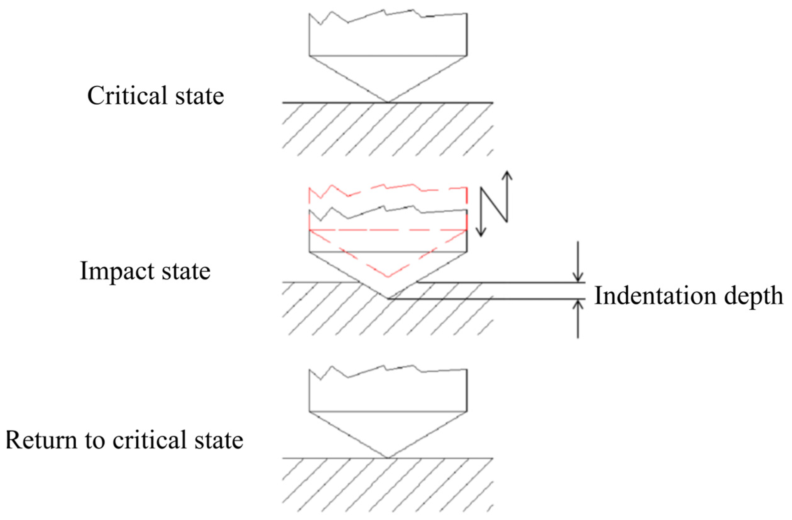
In this study, coating tools were prepared using the CVD method. Four different CVD coating tools, labeled as A, B, C, and D, respectively, were prepared by varying the deposition thickness of three coatings: TiCN, Al2O3, and TiN. The impact test and cutting test were conducted on these four tools. Table 1 shows the layer parameters of the four coating tools, and Figure 1 depicts the structure of the prepared coating tools. The substrate was made of a hard alloy material produced by Xiamen Golden Egret Special Alloy Co., Ltd. (Xiamen, China), brand GU20. Its chemical composition was 10.3% Co and 89.7% WC, with a grain size of 0.8 µm. First, coating A was prepared as a TiN layer with a thickness of 1.47 µm. The thickness of the Al2O3 layer was 4.33 µm and the TiCN layer thickness was 9.45 µm. Coating B was formed by increasing the thickness of each layer of coating A by 30%; coating C only had two layers, with 5.08 µm of Al2O3 and 9.96 µm of TiCN; coating D reduced the thickness of the TiN layer and Al2O3 layer, but increased the thickness of the TiCN layer, making its total thickness consistent with that of coating A.

2.2. Test Principle

The mechanical motion module of the cyclic impact test device was composed of a linear motor and a two-dimensional slide. The linear motor adopted Kollmorgen’s linear motor rotor (model IC22150A2TRP1) and linear motor stator (model MC1500512001), supplemented by a marble base, guide rail drag chain, roof, and grating ruler. The overall representation was in the form of a linear motor, as shown in Figure 2. The linear motor actuator and the linear motor stator rod, as well as the guide rail drag chain, were used to achieve the relative motion of the fixed part of the electric motor. The grating ruler was used to provide accurate position information, and the roof was placed on the linear motor actuator to load the “piezoelectric actuator” onto the linear motor. The linear motor was driven by Kollmogen’s AC (alternating current) driver (model AKD-P01206-NBEC-0000), thus achieving linear motion of the piezoelectric actuator. The schematic diagram of the entire device is shown in Figure 2, and the main parameters of the linear motor device are shown in Table 2.
The sample was connected to the vibration output end of a piezoelectric actuator (PhysikInstrumente’s P-843.40), and its cyclic vibration signal was modulated and output by a signal generator. Then, the signals were amplified and processed by Kistler’s amplifier circuit module (E-504.00F) and closed-loop feedback control circuit module (E-509.S1), respectively. Finally, the signal was output to a piezoelectric actuator, which generated cyclic vibration under the action of an electric field. The cyclic impact between the sample and the diamond indenter was generated by the cyclic vibration of the piezoelectric actuator. In [24], the sample was attached to a two-dimensional slide, while in this platform, the sample was attached to the sample stage and connected to a piezoelectric actuator with a thread. At the same time, the pressure head was connected to the force measuring instrument and fixed on the two-dimensional slide. This improvement makes it more efficient to replace the sample in practical applications.
The data acquisition module comprises a dynamometer sensor, a charge amplifier, and a data acquisition card. The dynamometer sensor was a Kistler type 9203 single component micro force sensor that was fixed to the two-dimensional slider with a thread. It operated based on the principle of piezoelectric measurement, where the force acting on the highly sensitive measuring element generates a proportional electric charge at the signal output, which is then converted into an evaluable process signal or curve via the charge amplifier. The force measuring instrument has a measuring range of −500–500 N. The charge amplifier used was a Type 5018A single-channel charge amplifier produced by the same company as the dynamometer sensor. The data acquisition card utilized was the SIRIUS MINI data acquisition system, which enabled the collected force signals to be analyzed and processed on a computer via its supporting software.
Previous studies have indicated that the coating surface of a tool undergoes cyclic fatigue impact in the range of 1–1000 Hz during milling processes. In this paper, we focus on investigating the cyclic fatigue impact that occurs during critical contact between the coating tool and the workpiece.
During the impact test, the coating sample was brought into critical contact with the indenter. The coating sample was attached to the end of the ultrasonic horn and installed on the linear motor. The linear motor then slowly moved the coating sample towards the indenter until contact was made, as indicated by the contact force signal between the coating sample and the indenter reaching 0.01 N.
As shown in Figure 3, once critical contact state was achieved, the power to the signal generator was turned on. The piezoelectric actuator drove the coating sample cyclically, causing the coating sample to be cyclically impacted by the indenter. The number of impact cycles was controlled by setting the impact time. Once the working time of the piezoelectric actuator reached the set value, it automatically stopped, and the motor system was controlled to withdraw the indenter, separating it from the coating sample.

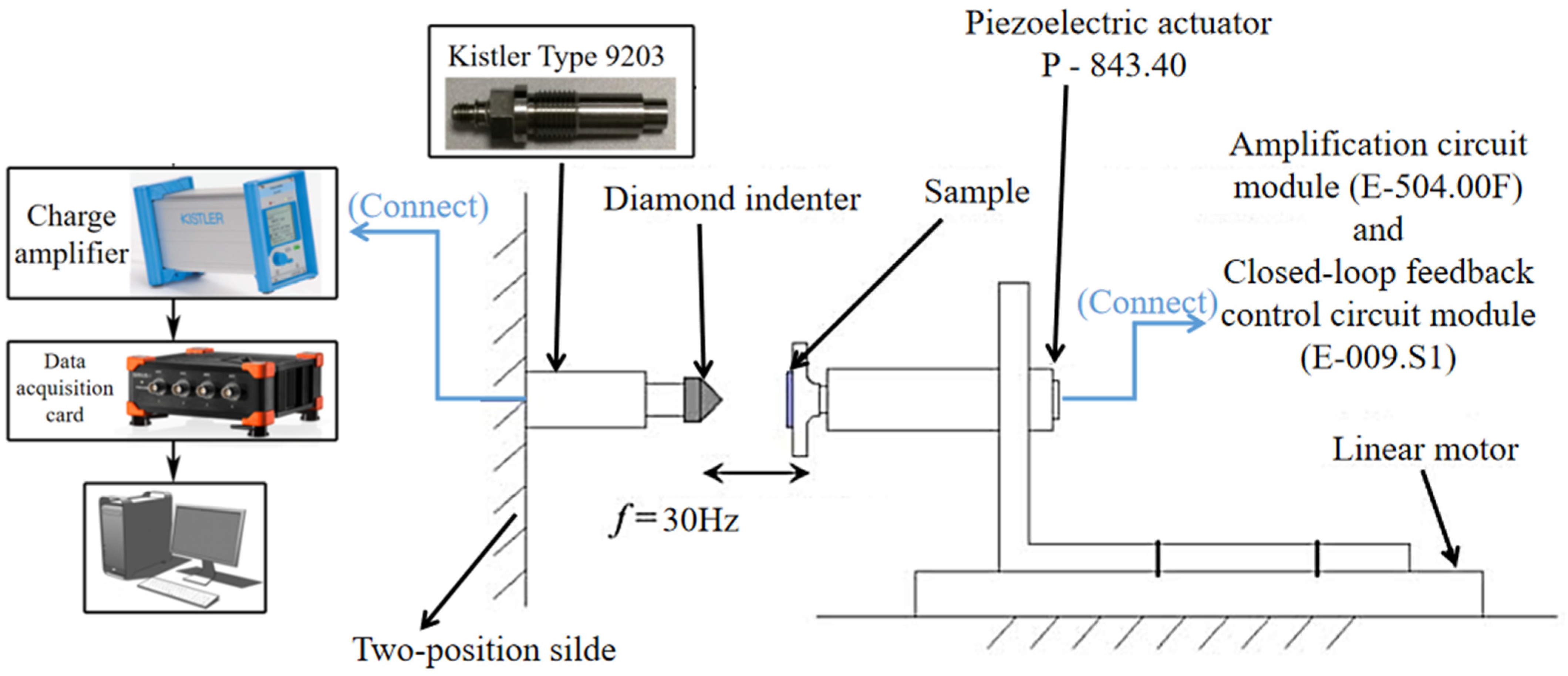
2.3. Design of the Impact Test

The indenter used was a Rockwell conical diamond indenter with a fillet radius of 0.05 mm. One end of the dynamometer was attached to the indenter, while the other end was connected to a charge amplifier. The coating sample was secured onto the vibration output end of the piezoceramic actuator, which was then fixed onto the linear motor as a whole via threading, allowing it to move horizontally.
In the cyclic impact test, the impact time was set to 240 s. During the milling process, the speed of the milling cutter is usually 1800 r/min, and each cutting tooth is impacted 30 times per second. Therefore, the impact frequency was set to 30 Hz to simulate the impact on the cutting tooth at a milling speed of 1800 r/min. In addition, the load range of the cutting tool during milling is 1–5 GPa. Therefore, different impact depths were set in the early stage of this experiment to obtain different loads. In order to ensure that the test results did not have contingency, three points at different positions on the sample were randomly selected for a fatigue test in each group of tests, and three control experiments were carried out. Through observation, it was found that the results of the three groups of experiments were consistent. The impact depth H of this experiment was set to 20/25/30/35 µm (the piezoelectric actuator used in the experiment was a P-843.40, produced by PhysikInstrumente. The amplitude of the piezoelectric actuator was controlled by controlling the voltage output from the signal generator. The amplitudes of 20/25/30/35 µm correspond to voltage signals of 3.33/17/5.83 V, respectively), and these loads were in the range of 1–5 GPa. Through the above setup, the impact of the coating tool was finally set to approximate the milling process. The parameter settings for the cyclic impact test are shown in Table 3.

3. Results and Discussion

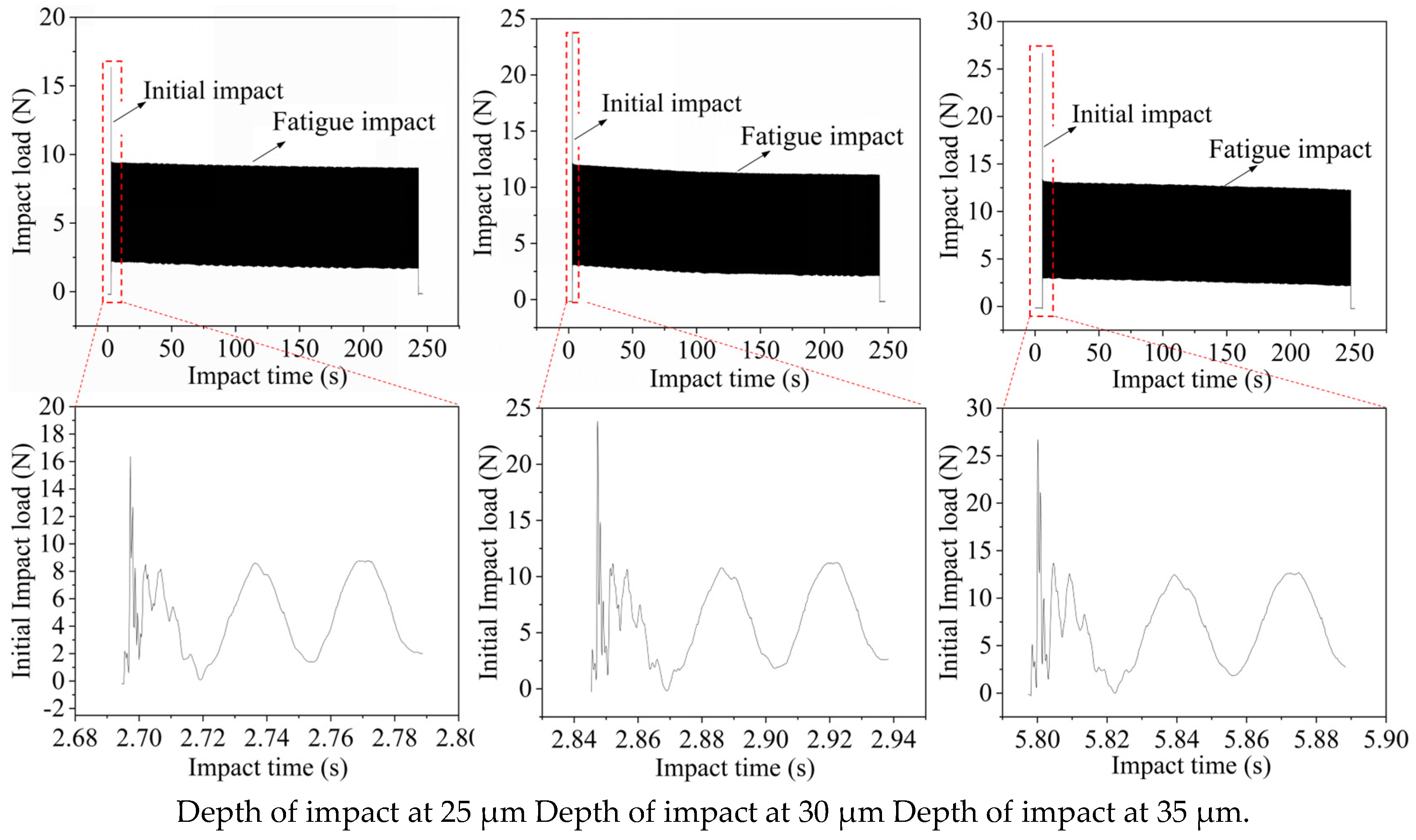
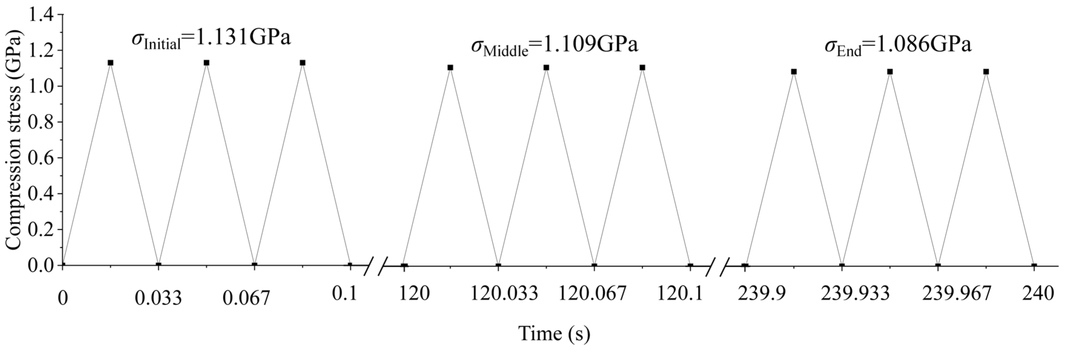
3.1. Cyclic Contact Stress Analysis

Figure 4 shows the impact load of coating A after cyclic impact at different impact depths. As can be seen from the figure, each coating first has a large initial impact load when it is impacted, then quickly enters the fatigue impact stage, and the initial impact load and fatigue impact load increase with the increase in impact depth (taking coating A as an example, when the impact depth is 25 µm the fatigue impact load is 9.42 N, and when the impact depth is 35 µm the fatigue impact load is 13.21 N). By observing the impact value of the whole impact process, it can be found that the coating slowly fails in the impact process due to the long-time impact, which can be proved by the slow decline of the impact value of the fatigue impact cut-off energy. In addition, the impact force at the initial impact stage is very unstable, which is a phenomenon of the first impact under various impact conditions. By comparing the force signal graphs of each coating at different impact depths, it was found that there is no significant difference in the force conditions of each coating.
In addition to the cyclic impact loads of coating A at different impact depths, shown in Figure 4, the other three coating tools were also subjected to cyclic impact tests. The cyclic impact loads of each coating tool during the impact process are shown in Table 4 below.
By observing the impact loads of different coatings at different impact depths, it can be concluded that the coatings have a large initial impact load at the first time of impact. After that, they enter the stable fatigue impact stage, where the impact load increases with the depth of impact. At the same depth of impact, the initial impact load and fatigue impact load of the four coatings are comparable.

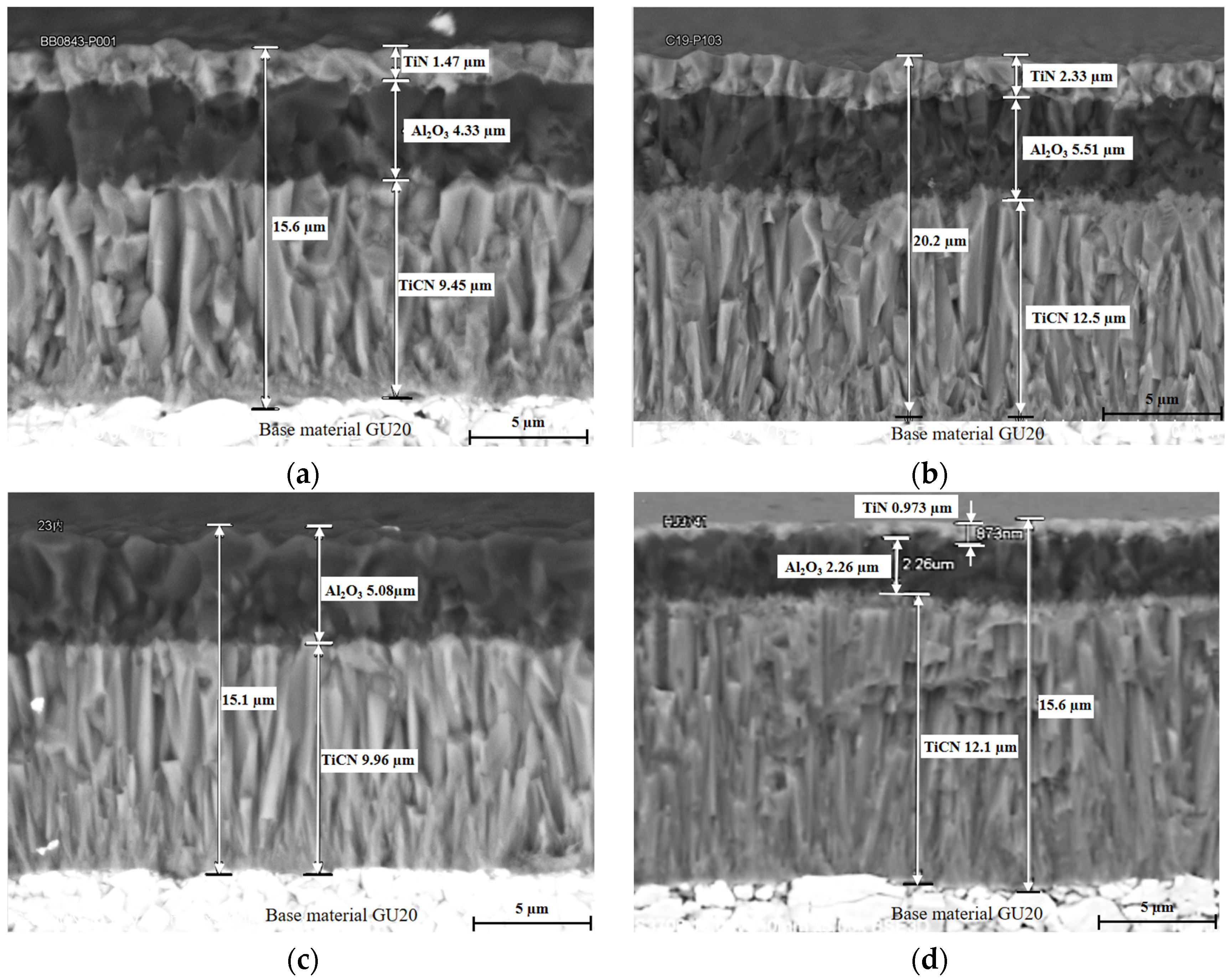
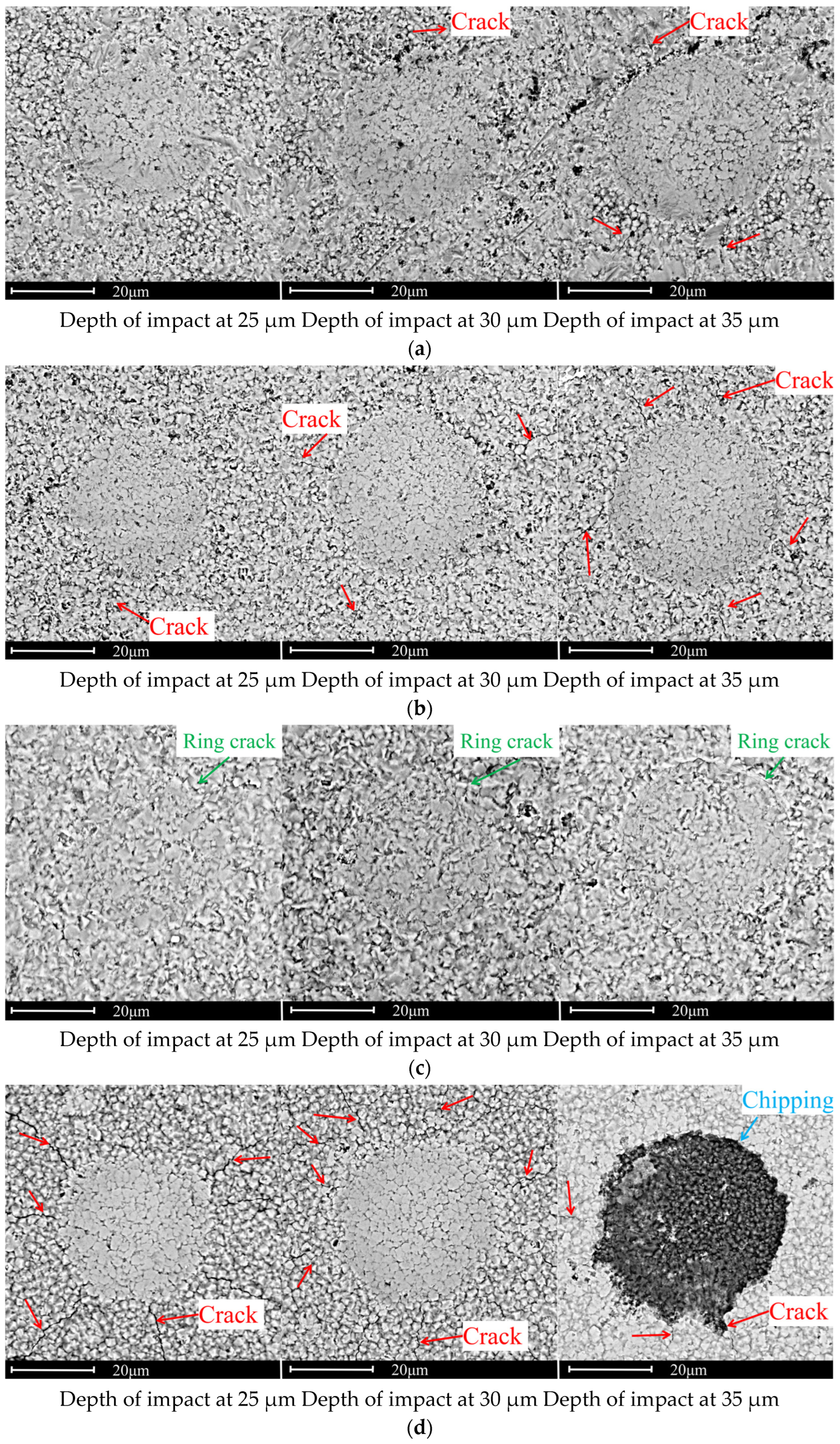
3.2. SEM Investigation

A scanning electron microscope was used to observe and study the surface morphology of the coatings after the cyclic impact test. Figure 5 illustrates the surface topography of the tool coatings after cyclic impact at different impact depths. It can be seen from the figure that the surface failure of each coating sample increases with the increase in impact depth, and the failure forms of sample A, sample B, and sample D are mainly radial crack, while the failure form of sample B is mainly annular crack. The damage of four samples under the same test parameters is most significant in sample D, where the surface layer of sample D completely fell off at an impact depth of 35µm. Sample B was slightly more damaged than sample A.
From a macroscopic perspective, the impact depth H increased from 25 µm to 35 µm, resulting in an increase in the degree of damage for each coating. Upon observing the damage of the different coatings, it is evident that the degree of damage for samples B and D is significantly greater than that of sample A. Furthermore, the damage observed in all three coatings is primarily radial cracking.

3.3. Discussion

At the same depth of impact, coating D exhibited the most significant damage. Numerous radial cracks were observed at an impact depth H of 25 µm, while surface spalling occurred at a depth H of 35 µm. Upon examining the impact load F at 35 µm, it was found that coating D experienced an impact for 47 s at that depth. The impact load F rapidly decreased from 13.46 N to 13.06 N within 12 s, which was slightly steeper than the slope observed during the initial and fatigue impact stages. It is inferred that the TiN coating on the surface of coating D spalled during this period. When comparing coating A and coating C, it was observed that coating A had relatively fewer ring cracks, while coating C had more. These key damage characteristics reflect different failure mechanisms during impact.
The impact condition of the tool samples during the impact process was analyzed. Using the experiment on tool sample A at an impact depth of 25 µm as an example, it was observed that the tool first experienced an initial impact with a large load, followed by entering the fatigue impact stage. Based on this observation, it was concluded that
σ = N S
Based on the above formula, the impact stress of each coating tool in the process of cyclic impact was calculated. As shown in Table 5, the impact stress of the coating tool in the cyclic impact process was basically close to 1 GPa, which accords with the impact force of the milling tool in the process of milling.
The contact stress of the coating can be calculated using the formula above, which can also be applied to calculate the coating’s stress during the fatigue impact stage. As Figure 6 shows, due to the prolonged impact test time, the coating gradually deteriorated under sustained impact, as evidenced by the gradual but minor reduction in the impact force during the fatigue stage. The results showed that the initial impact compressive stress of each coating sample, corresponding to the impact depth, was similar, and it was also similar to the subsequent fatigue impact stress for all four samples, indicating a consistent trend. As the impact progressed, each coating tool sample exhibited some degree of failure. A comparison of the final compressive stress of each sample revealed that the impact stress of each coating sample decreased as the impact depth increased, suggesting that deeper impacts were more likely to cause coating failure.
In impact tests, cracks can be caused by both tensile and compressive stresses during cyclic impact. Based on the classical Hertzian crack development characteristics, annular cracks are typically caused by tensile stress, whereas radial cracks are caused by compressive stress.
Upon comparing coatings A and B, it was observed that despite increasing the thickness of TiCN in coating B, its impact resistance was lower than that of coating A. At the same impact depth, the compressive stress of both samples was similar, but the tensile stress of coating A was higher than that of coating B. Upon examining the surface morphology after impact, it was revealed that the main failure mode of both samples was radial cracking. However, the radial cracking of coating B was more severe than that of coating A, which suggests that the thicker bonding layer reduced the coating’s impact resistance. This cannot explain the feedback effect of the two samples on tensile stress.
By comparing coating B and coating D, it was found that the TiCN and Al2O3 thickness of coating D was reduced. By observing the surface of coating D after impact, it was found that the surface layer of coating D was spalling and the Al2O3 layer was completely shed, resulting in lower impact resistance compared with coating A and coating B.
Comparing coating A and coating C, the main difference between them was the absence of a TiN surface layer in coating C. Upon observing the surface after impact, a large number of annular cracks were found on the surface of coating C, and the tensile stress of the two samples was similar, indicating that the tensile strength of coating C without a TiN surface was lower than that of coating A. This suggests that the impact resistance of coating C is lower than that of coating A.
By comparing the damage situation of four coating tools, it was found that they were subjected to similar stress conditions, but their damage was different. The surface morphology of coating tool A was the most complete among the four samples, indicating that coating tool A has the best ability to resist compressive and tensile stresses; the surface damage of coated tool B was slightly increased compared with coated tool A in terms of radial cracks, but no circular cracks appeared yet, indicating that coated tool B has a better ability to resist tensile stress, but its ability to resist compressive stress is slightly lower than that of coated tool A. The surface damage of coating tool C was mainly caused by circular cracks, without obvious radial cracks, indicating that its resistance to compressive stress is slightly stronger than that of coating tools A and B, but its resistance to tensile stress is poor; coating tool D exhibited a large number of radial cracks at an impact depth of 25 µm, and surface delamination occurred at an impact depth of 35 µm, indicating its poor compressive stress ability, but its resistance to tensile stress cannot be determined yet. In summary, coated tool A has the best fatigue resistance, while coated tools B and C are slightly weaker, and coated tool D exhibits the worst fatigue resistance.

4. Conclusions

A cyclic impact system based on a piezoelectric actuator was invented, and the impact frequency can be adjusted. In this experiment, the impact frequency was set to 30 Hz; the cyclic impact load was obtained by controlling the impact depth to simulate cyclic impact during the cutting process. Four coating tools of different layer thicknesses were designed and prepared for this experiment. In this experiment, the difference in impact resistance of coating tools with different layer thicknesses was found:
(1)
Coating tool B increased the total layer thickness of coating A by 1.3 times. The study found that under the same impact cyclic load, the surface damage of coated tool B increased by about 10% compared with that of coated tool A, indicating that the fatigue impact resistance of coated tool B, with an increase in total thickness, was slightly lower than that of coated tool A.
(2)
Comparing coating A and coating C, the difference between the two coatings is that coating tool C removed the TiN layer and increased the thickness of the Al2O3 and TiCN layers, and the overall thickness remained almost unchanged. It was found that the surface crack of coated tool C was slightly more than that of coated tool A, and the cyclic impact resistance of coated tool C was also slightly lower than that of coated tool A.
(3)
Compared with coating A and coating D, the difference between them is that coating D reduced the thickness of TiN and Al2O3 while increasing the thickness of bonding layer TiCN. However, the experiment found that this thickness change caused more cracks to appear in coated tool D. When the impact depth was 30 µm, the surface cracks of coated tool D increased by more than 50% compared with those of coated tool A. At an impact depth of 35 µm, there was even a phenomenon of surface layer peeling. It shows that the decrease in TiN and Al2O3 thickness and the increase in TiN make the cyclic impact resistance of coating tools obviously decrease.
After analyzing the above results, it was found that the presence of TiN coating mainly changes the surface damage form of the coating (radial cracks or circular cracks). The thickness of the TiN surface should not be too small, otherwise surface peeling may occur. In this experiment, an increase in the total thickness of the coating slightly reduced its performance. Therefore, among the four coating tools, coating tool A had the best performance, coating tool D had the worst performance, and coating tool B and coating tool C had similar performances, both slightly lower than that of coating tool A. In subsequent research, coating tools with different coating parameters can be further prepared to obtain the optimal coating thickness through experiments.

Author Contributions

Conceptualization, J.D., F.J. and H.Y.; investigation, J.D. and T.Z.; funding acquisition, F.J., X.Z., T.Z. and H.Y.; data curation, X.Z.; methodology, D.Z.; supervision, D.Z. and F.W.; resources, H.Z.; validation, H.Z.; software, H.X.; writing—original draft, H.X. and X.W.; writing—review and editing, F.W. and L.Y.; visualization, X.W. and L.Y. All authors have read and agreed to the published version of the manuscript.

Funding

This work was supported by the Integration Project of Industry and Research of the National Natural Science Foundation of China (No. 52275428), the National Natural Science Foundation of China (No. 52205466), the Natural Science Foundation for the Science and Technology Project of Fujian Province (No. 2021J05167), and the Foundation of State Key Laboratory of Digital Manufacturing Equipment and Technology (Grant No. DMETKF2022002).

Institutional Review Board Statement

Not applicable.

Informed Consent Statement

Not applicable.

Data Availability Statement

Data are contained within the article.

Acknowledgments

The authors would like to thank Xiamen Golden Egret Special Alloy Co., Ltd. for their support in preparing coating samples.

Conflicts of Interest

The authors declare no conflict of interest.

References

  1. Blinkov, I.V.; Belov, D.S.; Volkhonsky, A.O.; Sergevnin, V.S.; Nizamova, A.N.; Chernogor, A.V.; Kiryukhantsev-Korneev, F.V. Heat Resistance, High-Temperature Tribological Characteristics, and Electrochemical Behavior of Arc-PVD Nanostructural Multilayer Ti–Al–Si–N Coatings. Prot. Met. Phys. Chem. 2018, 54, 416–424. [Google Scholar] [CrossRef]
  2. Antonyuk, V.S.; Soroka, E.B.; Kalinichenko, V.I. Providing adhesion strength for a substrate-coating system under contact loading. J. Superhard Mater. 2008, 30, 133–138. [Google Scholar] [CrossRef]
  3. Wang, H.; Lu, H.; Song, X.; Yan, X.; Liu, X.; Nie, Z. Corrosion resistance enhancement of WC cermet coating by carbides alloying. Corros. Sci. 2019, 147, 372–383. [Google Scholar] [CrossRef]
  4. Sima, M.; Özel, T. Modified material constitutive models for serrated chip formation simulations and experimental validation in machining of titanium alloy Ti–6Al–4V. Int. J. Mach. Tools Manuf. 2010, 50, 943–960. [Google Scholar] [CrossRef]
  5. Liyao, G.; Minjie, W.; Chunzheng, D. On adiabatic shear localized fracture during serrated chip evolution in high speed machining of hardened AISI 1045 steel. Int. J. Mech. Sci. 2013, 75, 288–298. [Google Scholar] [CrossRef]
  6. Gassner, M.; Schalk, N.; Tkadletz, M.; Czettl, C.; Mitterer, C. Thermal crack network on CVD TiCN/α-Al2O3 coated cemented carbide cutting tools. Int. J. Refract. Met. Hard Mater. 2019, 81, 1–6. [Google Scholar] [CrossRef]
  7. Zha, X.; Chen, F.; Jiang, F.; Xu, X. Correlation of the fatigue impact resistance of bilayer and nanolayered PVD coatings with their cutting performance in machining Ti6Al4V. Ceram. Int. 2019, 45, 14704–14717. [Google Scholar] [CrossRef]
  8. Wang, T.; Zha, X.; Chen, F.; Wang, J.; Li, Y.; Jiang, F. Mechanical impact test methods for hard coatings of cutting tools: A review. Int. J. Adv. Manuf. Technol. 2021, 115, 1367–1385. [Google Scholar] [CrossRef]
  9. Beake, B.D.; Bird, A.; Isern, L.; Endrino, J.L.; Jiang, F. Elevated temperature micro-impact testing of TiAlSiN coatings produced by physical vapour deposition. Thin Solid Films 2019, 688, 137358. [Google Scholar] [CrossRef]
  10. Lamri, S.; Langlade, C.; Kermouche, G. Damage phenomena of thin hard coatings submitted to repeated impacts: Influence of the substrate and film properties. Mater. Sci. Eng. A 2013, 560, 296–305. [Google Scholar] [CrossRef]
  11. Lamri, S.; Langlade, C.; Kermouche, G. Failure mechanisms of thin hard coatings submitted to repeated impacts: Influence of the film thickness. Adv. Mat. Res. 2010, 112, 73–82. [Google Scholar] [CrossRef]
  12. Beake, B.D.; Lau, S.P.; Smith, J.F. Evaluating the fracture properties and fatigue wear of tetrahedral amorphous carbon films on silicon by nano-impact testing. Surf. Coat. Technol. 2004, 177, 611–615. [Google Scholar] [CrossRef]
  13. Zhao, G.; Zhang, X.; Zavalnyi, O.; Liu, Y.; Xiao, W. Extended roughing operations to ISO 14649-11 for milling T-spline surfaces. Int. J. Adv. Manuf. Technol. 2019, 102, 4319–4335. [Google Scholar] [CrossRef]
  14. Hovsepian, P.E.; Luo, Q.; Robinson, G.; Pittman, M.; Howarth, M.; Doerwald, D.; Tietema, R.; Sim, W.M.; Deeming, A.; Zeus, T. TiAlN/VN superlattice structured PVD coatings: A new alternative in machining of aluminium alloys for aerospace and automotive components. Surf. Coat. Technol. 2006, 201, 265–272. [Google Scholar] [CrossRef]
  15. Khorasani, A.M.; Gibson, I.; Goldberg, M.; Doeven, E.H.; Littlefair, G. Investigation on the effect of cutting fluid pressure on surface quality measurement in high speed thread milling of brass alloy (C3600) and aluminium alloy (5083). Measurement 2016, 82, 55–63. [Google Scholar] [CrossRef]
  16. Niu, J.; Huang, C.; Li, C.; Zou, B.; Xu, L.; Wang, J.; Liu, Z. A comprehensive method for selecting cutting tool materials. Int. J. Adv. Manuf. Technol. 2020, 110, 229–240. [Google Scholar] [CrossRef]
  17. Arriola, I.; Whitenton, E.; Heigel, J.; Arrazola, P.J. Relationship between machinability index and in-process parameters during orthogonal cutting of steels. CIRP Ann. 2011, 60, 93–96. [Google Scholar] [CrossRef]
  18. Baizeau, T.; Campocasso, S.; Rossi, F.; Poulachon, G.; Hild, F. Cutting force sensor based on digital image correlation for segmented chip formation analysis. J. Mater. Process. Technol. 2016, 238, 466–473. [Google Scholar] [CrossRef]
  19. Zha, X.; Jiang, F.; Xu, X. Investigation of modelling and stress distribution of a coating/substrate system after an indentation test. Int. J. Mech. Sci. 2017, 134, 1–14. [Google Scholar] [CrossRef]
  20. Zha, X.; Jiang, F.; Xu, X. Investigating the high frequency fatigue failure mechanisms of mono and multilayer PVD coatings by the cyclic impact tests. Surf. Coat. Technol. 2018, 344, 689–701. [Google Scholar] [CrossRef]
  21. Zha, X.; Wang, T.; Chen, F.; Wang, J.; Lin, L.; Lin, F.; Xie, H.; Jiang, F. Investigation the fatigue impact behavior and wear mechanisms of bilayer micro-structured and multilayer nano-structured coatings on cemented carbide tools in milling titanium alloy. Int. J. Refract. Met. Hard Mater. 2022, 103, 105738. [Google Scholar] [CrossRef]
  22. Zha, X.; Wang, T.; Guo, B.; Chen, F.; Lin, L.; Zhang, T.; Jiang, F. Research on the oxidation resistance and ultra-high frequency thermal fatigue shock failure mechanisms of the bilayer and multilayer nano-coatings on cemented carbide tools. Int. J. Refract. Met. Hard Mater. 2023, 110, 106043. [Google Scholar] [CrossRef]
  23. Wang, T.; Zha, X.; Chen, F.; Wang, J.; Lin, L.; Xie, H.; Lin, F.; Jiang, F. Research on cutting performance of coated cutting tools by a new impact test method considering contact stress condition caused by segmented chips. J. Manuf. Process. 2021, 68, 1569–1584. [Google Scholar] [CrossRef]
  24. Bouzakis, K.D.; Skordaris, G.; Bouzakis, E.; Michailidis, N. Characterization methods and performance optimization of coated cutting tools. Ann. Fac. Eng. Hunedoara 2014, 12, 121. [Google Scholar]
Figure 1. The structure of the prepared coating tools. (a) Coating A, (b) Coating B, (c) Coating C, (d) Coating D.
Coatings 13 00815 g001
Figure 2. Schematic diagram of the overall device.
Coatings 13 00815 g002
Figure 3. Schematic diagram of the impact test.
Coatings 13 00815 g003
Figure 4. The impact load of a cyclic impact at different impact depths for coating A.
Coatings 13 00815 g004
Figure 5. The surface topography of the tool coating after cyclic impact. (a) Coating A; (b) Coating B; (c) Coating C; (d) Coating D.
Coatings 13 00815 g005
Figure 6. Fatigue compressive stress changes throughout the whole process.
Coatings 13 00815 g006
Table 1. Coating parameters of different samples.
SampleOuter Layer
TiN (µm)
Middle Layer
Al2O3 (µm)
Inner Lying
TiCN (µm)
Film Thickness (µm)
A1.474.339.4515.6
B2.335.5112.520.2
C/5.089.9615.1
D0.9732.2612.115.6
Table 2. Main parameters of the linear motor.
Electric Machine ParameterData
Rated thrust (N)67
Peak thrust (N)202
Top speed (m/s)4
Peak current duration (s)<1
Raster resolution (µm)0.1
Table 3. The parameter settings of the cyclic impact test.
Frequency of Impact (Hz)Time of Impact (s)Depth of Impact H (µm)
3024025
30
35
Table 4. The fatigue impact force F.
25 µm30 µm35 µm
Coating A9.42 N12.06 N13.21 N
Coating B8.72 N11.12 N13.09 N
Coating C8.84 N10.33 N12.63 N
Coating D9.22 N11.15 N13.77 N
Table 5. The mean fatigue compression stress.
25 µm30 µm35 µm
Coating A1.109 GPa1.105 GPa0.993 GPa
Coating B1.023 GPa1.031 GPa0.982 GPa
Coating C1.094 GPa1.008 GPa1.013 GPa
Coating D1.092 GPa1.030 GPa1.038 GPa
Disclaimer/Publisher’s Note: The statements, opinions and data contained in all publications are solely those of the individual author(s) and contributor(s) and not of MDPI and/or the editor(s). MDPI and/or the editor(s) disclaim responsibility for any injury to people or property resulting from any ideas, methods, instructions or products referred to in the content.

