Article

Effect of Local Remelting and Recycled WC-Co Composite Reinforcement Size on Abrasive and Erosive Wear of Manual Arc Welded Hardfacings

1
Department of Electrical Engineering and Automation, Czech University of Life Sciences Prague, 165 00 Praha-Suchdol, Czech Republic
2
Department of Mechanical and Industrial Engineering, Tallinn University of Technology, 12616 Tallinn, Estonia
3
Department of Mechanical, Energy and Biotechnology Engineering, Vytautas Magnus University, 44248 Kaunas, Lithuania
*
Author to whom correspondence should be addressed.
Coatings 2023, 13(4), 734; https://doi.org/10.3390/coatings13040734
Submission received: 24 February 2023 / Revised: 26 March 2023 / Accepted: 30 March 2023 / Published: 4 April 2023
(This article belongs to the Special Issue Enhanced Mechanical Properties of Metals by Surface Treatments)

Abstract

:
The hardfacings reinforced by recycled (cermet inserts of machining tools) WC-Co composite particles applied by manual arc welding can be used for protection against abrasive and erosive wear. Two categories of coatings were analyzed: with and without thermal treatment (local remelting). The hardfacings were tested under abrasive (low and medium stress) and erosive (high stress) conditions. In elevated temperature erosive conditions, coatings without heat treatment have up to two times higher wear resistance than reference material. Under low-stress conditions, coatings with the finest reinforcing particle size (180–355 µm) treated with local remelting demonstrated more than 10 times higher wear resistance than reference material. The optimal reinforcement size selection depends on the application conditions (low, average, or high stress). In most test conditions, the local remelting did not provide additional improvement. A scanning electron microscope was used for the characterization of wear mechanisms. The relation between mechanical properties and wear rates was found only for some conditions.

Graphical Abstract

1. Introduction

The metal processing industry uses high amounts of tungsten products to process workpieces. The lifetime of metal cutting and machining tools’ cermet inserts can be extremely short (sometimes just 15 min). The material loss during that time is insignificant (just a few percent), and the remaining part of the insert is discarded. Tungsten and its products (cermet inserts), according to authors [1,2,3], can be recycled. The inserts can be crushed into powder that can be used to reinforce thick (up to 10 mm) coatings to increase their wear resistance [4]. Such coatings are usually produced by well-controlled automated plasma and laser technologies. Their properties have been investigated [5,6,7], and it is possible to remelt a thermally sprayed coating to improve its inherent defects (pores, unmelted particles, poor mechanical bonding) [8]. Recycled insert powders can be used for sample preparation for the sintering process [9,10] to analyze mechanical or microstructural properties. However, information about manual arc welded hardfacings is scarce. Agriculture often uses manual arc welding to improve or repair tillage tools [11,12]. The conditions of the weld pool are less controlled, and significant or complete melting of reinforcing particles, defects (pores, slag inclusions, oxides, a lack of or low adherence between layers, etc.), as well as the generation of thermal stresses, especially in the case of thick multilayered coatings, take place [13]. According to previous investigations, the size of 135 µm WC (unused; not recycled; not composite) reinforcing particles provides a higher resistance to the thermal cracking that appears during the welding process, but the removal of coarser WC particles requires more time (and leads to higher wear resistance) [14].
The additional thermal (heat) treatment could be applied as an annealing process [15] or preheating of the substrate material before welding [16,17], remelting the applied surface by laser [8,18], or by the tungsten inert gas (TIG) method [19]. Preheating the substrate material before welding reduces thermal stress between the hardfacing and substrate material [13]. Surface remelting can also improve dilution of reinforced particles or metallurgical bonding between layer and substrate, as well as the homogeneity of the formed hardfacing [20]. However, in some cases, gas pockets can lead to microporosities near the substrate and a completely melted layer after remelting by the TIG [19]. The recycled reinforcement particles may improve the wear resistance of manual arc welded hardfacings, but welding quality must be monitored [14]. The welding defects can be removed with TIG’s previously mentioned thermal treatment method. The remelting carried out by the TIG increases the dissolution and reprecipitation of reinforcing particles.
Recycling metal cutting and machining tools’ cermet inserts would prevent wasting critical raw material. Manual arc welding electrodes with flux coverings incorporating crushed cermet particles can create hardfacings resistant to abrasive or erosive wear conditions. The current work aims to study the effect of remelting on the performance of multilayered manual arc welded hardfacings with various sizes of recycled reinforcement particles under low-, medium- (abrasive), and high-stress (erosive) wear testing conditions.

2. Materials and Methods

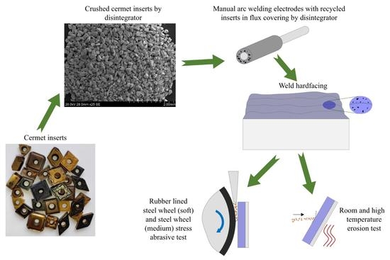
2.1. Crushing of the Inserts

The collected mixture of various machining and turning tool inserts was mainly composed of WC-Co materials, but some minor presence (less than 10%) of TiC, VC, NbC, and MoC was possible.
The inserts were crushed in two steps by disintegrators DSL-350 and DSL-175 (rough and fine crushing). Powders were sieved by Fritsch Analysette 3 into six fractions: 180–355, 355–500, 500–710, 710–1000, 1000–1400, and 1400–2000 μm (Figure 1). The powder with a size less than 180 µm was not used in this research because of the high content of adhered steel resulting from contact with the working elements of the disintegrator. It is essential to point out that the particles of such a powder are made of composite material (mainly WC grains cemented by cobalt). This might reduce the dilution of WC grains during welding and lead to higher wear rates [21].

2.2. Preparation of Manual arc Welding Electrodes

The preparation of covered electrodes and application of the manually welded arc layers was performed in cooperation with JSC “Anykščių Varis”, the research center of the producer of electrodes on an industrial scale. The welding electrode for the composite coating application was composed of the central core wire covered by the flux, which had inclusions of recycled inserts (reinforcement). The diameter of the core wire was 3.2 mm, and the length was 350 mm. The grade of the low-carbon ferritic–pearlitic steel wire was SWRY–21 according to JIS G3503 or CB-08A according to GOST 2246–70.

2.3. Preparation of the Hardfacings

Two groups of hardfacings and three reference materials were investigated. The designation of sample grades consists of two digits (1X or 2X), where the first digit indicates the group (1—without; 2—with additional thermal treatment), and the second digit indicates the size of reinforcing particles (1—finest; …; 6—coarsest). The list of materials is given in Table 1, along with their chemical composition.
All hardfacings were welded in four layers on top of SJ 355 (EN 10025-2:2004) steel substrate plates with dimensions of 80 (length) × 40 (width) × 10 (thickness) mm and were left to cool naturally to room temperature.
Later, the thermal treatment (local melting of the coating in an argon atmosphere to reduce the extent of defects) was conducted with the second group of samples (No. 21-26). The samples (21–26) were heated up to 300 °C and then locally heated up to 1600–1800 °C (melted) by a nonconsumable tungsten electrode in an argon gas field (ESAB, CADDY TIG 2200i AC/DC, North Bethesda, MD, USA). The electrode was manually moved along the longitudinal direction of the sample, and the approximately 2.5 mm wide and 80 mm long strip was treated in 10 s. After that, an electrode was shifted by approximately 2 mm, and the next strip was treated with an overlap of about 0.5 mm. Approximately 20 strips (area of 40 mm × 80 mm) were treated in close to 3 min. The bulk sample temperature was in the range of 500–1000 °C during thermal treatment. After treatment, the samples were placed in a chamber with a temperature of 350 °C, and cooling at a rate of 3 °C min−1 down to room temperature was performed to reduce thermal stresses (Figure 2).
Approximately 2 mm of the top surface of the hardfacing was removed during grinding. The steel substrate was partially removed by machining to provide a total thickness of samples (including coating and substrate) of 7 mm. Later, the samples were cut by Struers (Copenhagen, Denmark) Secotom 50 into the required shape (25 × 50 mm or 15 × 25 mm for abrasive and erosive tests, respectively).
The chemical composition was measured by BELEC compact-lab-N spectrometer. The TK-2M hardness testing machine performed the hardness measurement. At least five measurements were taken for chemical and hardness testing.

2.4. Abrasive and Erosive Wear Testing Conditions

To demonstrate the performance of hardfacings under a variety of conditions, three types of wear tests were carried out: (1) soft abrasion (low-stress) ASTM G65-04 standard (rubber wheel test); (2) medium-stress abrasion conducted similarly to ASTM G65-04 but with the assistance of a steel wheel; and (3) dynamic impacts (high-stress) by centrifugal accelerator at room and high temperature in accordance with GOST 23.201-78 standard (Figure 3). Each testing method has its application in agriculture, mining, or other industries sectors. The broader testing of the hardfacings improves the proper usage in the most familiar environment. Three testing conditions help to analyze deeper wear mechanisms specific to low-stress conditions (abrasive particles prevailing mechanism is dragging (scratching) along the sample surface), medium-stress conditions (rotation and partial fracturing of abrasive particles and higher local stresses in material’s surface), and high-stress conditions (erodent particles flying after exiting a centrifugal accelerator and creating an impact with a sample surface). The wear results will show applications where the hardfacing has higher strength and a lower wear rate. A detailed description of test conditions is shown in Table 2 and Table 3.
It should be mentioned that due to the deformation of the rubber wheel, the average pressure in contact changes only slightly during the test. In contrast, the steel wheel pressure is high at the beginning of the test and is reduced along with the increase in the wear scar size, and finally, it is even lower than that of the soft-stress abrasion test (Table 2). During testing with a steel wheel, there is a higher chance of abrasive particle fracture due to the metal’s higher stiffness than rubber [22]. In contact with rubber, the crushing of abrasive particles is almost eliminated.
Weighing before and after the abrasive and erosive tests was performed to the nearest 1 mg using KERN EG420–3NM and Mettler Toledo ME204 balances, respectively, to determine mass loss. The erosion rate was calculated according to the procedure described in [23,24].
In order to reduce the effect of oxidation on the precision of erosive wear measurement by weight change, the samples were preliminary oxidized in an electrical chamber, Nabertherm (Lilienthal, Germany) L9/13 with a PID temperature controller P330, at their test temperature with heating, cooling rates, and duration of oxidation similar to those applied during the erosion test.
After wear tests, the chemical composition of samples was determined by the EDS method with an SEM Hitachi TM-1000 Tabletop Scanning Electron Microscope (SEM) (Tokyo, Japan) equipped with a Bruker XFlash® 6|10 detector for element analysis, which was used for imaging as well. Each type of hardfacing test was performed two times under the same testing conditions.

2.5. Hardness and Macrohardness Measurement

The personal computer-controlled Universal hardness tester Zwick (Ulm, Germany) BZ 25 with Vickers indenter was used to test material properties. The tests were conducted in accordance with DIN 50359-1 and EN 14577-1 [25]. A sufficiently high load was applied to determine macro-properties due to the large size of reinforcing particles, their inhomogeneous distribution due to the coating application procedure, and the difference in densities of the phases. Table 4 shows indentation testing conditions.

3. Results

Figure 4 shows typical images of the cross-sections of the hardfacings. One of the most significant cracking of the reinforcing grains is found in sample No. 14 (reinforcing particle size of 710–1000 µm; Figure 4A). These grains are inside the first applied layer, indicating that preheating is important. The substrate plate was not heated up before welding the first layer. The temperature differences between the welded layer and substrate create residual stress acting on the reinforcing particles. The possible sinking of reinforcing particles is shown in Figure 4B (sample No. 26; WC particles of 1400–2000 µm). The significantly higher density of tungsten influences sinking in comparison to steel. Due to the close position of WC-Co particles to the substrate, it is possible to assume that the dilution of the base metal by hardfacing is limited. Figure 4B also demonstrates possible cracks in the low-carbon steel binder. The uniformity of carbide distribution in manual arc welded hardfacings can be improved by applying a higher welding current (energy input) [5].
Samples with additional remelting have reduced the size of reinforcing particles (Figure 4B, No. 26, particle size 1400–2000 µm) or resulted in the complete loss of particles (Figure 4D, No. 21, particle size 180–355 µm) due to dilution. There is a broader transition zone (fusion line) between (1) hardfacing and base metal and (2) reinforcing particles and steel binder (up to 100 µm) that is usually beneficial since it has a lower gradient and lower stresses.
The following sections present the results of the samples’ wear testing.

3.1. Low-Stress Abrasion Tests (with Rubber Wheel)

The results of the low-stress abrasion test indicate that additional thermal treatment (local remelting) has a generally negative effect—the average wear rate of hardfacings increases by 29 percent (Figure 5). However, not all the hardfacings had the same response to the treatment. The wear rate of the sample with the finest size of WC particles decreased by 35% (samples 11 vs. 21), while some samples with larger sizes of reinforcement particles had an extreme rise in wear (wear rate is up to two times higher; samples 23 vs. 13, 26 vs. 16). It is possible to conclude that in the case of low-stress abrasion, thermal treatment is only advantageous in the case of hardfacings with reinforcing particles with a size of 180–355 µm. The wear of Hardox 400 is significantly higher than that of hardfacings (3.7 and 2.6 times higher than coatings without or with thermal treatment, respectively). The wear of Mn steel is approximately twice as low as that of Hardox 400, while it is generally higher than that of hardfacings. Only coating 26 is less resistant to wear than Mn steel. The best coatings among their groups were 14, 21, and 24. This shows that in addition to the positive effect of thermal treatment for hardfacings with the finest reinforcement (180–355 µm, sample 21), there is an optimum particle size (coatings 14 and 24) of 710–1000 µm.

3.2. Medium-Stress Abrasion Tests (with Steel Wheel)

Medium-stress abrasion results (Figure 5) indicate that the increase in contact stresses (and typically observed shifting of abrasive particle behavior from scratching to rotation with indentation and fracturing) leads to a significant rise in wear rate. The wear rate during 3 min of average-stress abrasion is approximately 10 times higher than during 15 min of low-stress abrasion. The thermal treatment had a positive effect on all hardfacings. The average wear rate decreased by 13%. The lowest and most significant reduction (2 and 22%) was observed for samples 16 vs. 26 (coarsest) and 13 vs. 23, respectively. In conditions of medium-stress abrasion, the wear rates of Hardox 400 and Mn steel were similar to those of hardfacings without heat treatment, while after the heat treatment, the performance of all hardfacings was better (approximately 14%) than that of reference steels. The hardfacings with the highest hardness (16 and 22; Table 1) have the highest resistance in medium-stress abrasive conditions since they provide the highest resistance against indentation.

3.3. Solid Particle Erosion Tests at Room Temperature

As is usually expected, the wear rate of materials investigated under both angles of impact rose with the rise in impact velocity due to the increased kinetic energy of the flying erodent (Figure 6 and Figure 7).
The erosive wear rate results of hardfacings investigated under impact angles of 30° and 90° show (Figure 6 and Figure 7) that heat treatment negatively affected wear resistance. Only material 16 vs. 26 experienced almost no changes, or at the slowest test speed of 30 m·s−1 and an angle of 30°, the wear rate decreased.
In general, hardfacings with larger reinforcement particle sizes (1000–1400 and 1400–2000 µm) had the worst wear resistance if no heat treatment was provided (Figure 6 and Figure 7). However, after heat treatment, the coatings with the average size of hard particles (355–500 and 500–710) were the least suitable for erosion under impact angles of 30 and 90°. The coatings 11 and 21 had the lowest wear under an impact angle of 30° at all velocities, which illustrates the potential of hardfacings with small reinforcing particles.
During erosion with an impact angle of 30°, Mn steel and Hardox 400 have similar or lower (5–10% on average) wear resistance to the tested coatings, respectively; however, under normal impact angles, the steels have better wear resistance (1.7–2.7 times as compared to Hardox 400).
The sample No. 12 grain has a crack, which can appear during welding or erosion testing because of particle impact (Figure 8). Elongated grains have a lower tolerance to internal stresses than rounded ones. For example, sample No. 24 nicely incorporates a grain into the matrix. The matrix is plastically deformed and distributed over harder areas in sample No. 16 (particle size 1400–2000 µm). Reinforcing particles are washed around by the erodent particles because of different hardness between the carbide grain and the matrix. In some places, there is recognized plural splitting of the carbide grain (sample No. 25). When the reinforcing particle is examined with higher magnification, it is possible to observe its composite nature (sample No. 25), where that matrix is partially removed around the WC particles (1–5 µm) by the fine abrasive particles or fragments [19]. Microploughing on the surface of samples No. 11 and 21 is observed when erodent particles collide with the surface at the highest impact velocity of 80 m·s−1.
In most cases, it is difficult to predict a cutting direction because scratching direction is various and unpredictable. The erodent particles change direction after the first impact with a surface or collision between each other. Specifically, this can be noticed after erosion with the highest impact velocity (80 m·s−1), where scratches appear very chaotically.
The volumetric erosion rate can be expressed in the general form [24]
I = a v m
where a is the coefficient that depends on the target material, impact angle, and eroding particle properties; v is impact velocity, m·s−1; and m is the index. Table 5 contains the data for estimating erosion rates under both impact angles in the range of studied velocities (30–80 m·s−1).
The energy supplied by an erodent particle to the sample during normal angle impact is higher than during oblique angle impact. As a result, it is expected to observe more severe damage. The intensity of carbide breakage (fragmentation), relocation of initial material, embedment of erodent fragments, and fatigue of the metallic matrix, i.e., the formation of a mechanically mixed layer, is increased (Figure 9). The rough surface structure can be seen on sample No. 15’s surface. Compared to Figure 8 (impact angle 30°), a higher impact angle (90°) does not create as many chaotical scratches as a lower impact angle. The erodent particles at a higher impact angle have a straight path and create one impact on the sample surface, which either deforms the matrix or, after impact with a higher hardness carbide grain, bounces back from the sample surface. In comparison, a lower impact angle repeatedly creates impacts on the surface.

3.4. Solid Particle Erosion Tests at Elevated Temperatures

AISI 316 stainless steel was used as a reference material instead of Hardox 400 and Mn steel (used for room temperature tests) due to their excessive oxidation at such elevated temperatures.
The results of groups of hardfacings with and without thermal treatment are shown separately for better clarity of the images, to make it easier to track the effect of temperature on the wear rate of each material independently and its performance within its group.
The wear rate of hardfacings without thermal treatment under an impact angle of 30° and a velocity of 80 m s−1 at temperatures of 350, 450, and 550 °C was lower than that of reference AISI316 stainless steel. In contrast, at 650 °C, the wear of coatings 11, 13, and 15 was higher (Figure 10).
At least three parameters are influenced by the rise in temperature: (1) softening (the hardness of materials is usually reduced at high temperatures), (2) change of internal stresses, and (3) oxidation. As seen in Figure 10, the wear rates of coatings 13 and 16 are lower at 450 and 550 °C than at 350 °C and perform very well at temperatures below 650 °C. These materials were usually not the best performers during abrasive or especially erosive testing at room temperature. This enables one to conclude that their performance is improved due to reduced brittleness or internal stresses. Material 16 had the highest W (WC) concentration and the highest hardness at room temperature (Table 1). Coating 12 performed quite well during average-stress abrasive wear testing, with an average erosion rate at 350, 450, and 550 °C and the lowest rate at 650 °C among the materials investigated.
The erosive wear rate of hardfacings after the thermal treatment (Figure 11) was quite similar to materials without thermal treatment. In addition to materials 23 and 26, material 25 also has relatively low wear rates at 350, 450, and 550 °C, which points to the conclusion that materials with average or larger reinforcement sizes may provide better erosive wear resistance at least at temperatures of 350–550 °C with an impact angle of 30°. The important fact that can also be observed from Figure 10 is that at 650 °C, all thermally treated hardfacings have lower wear resistance than reference stainless steel.
In order to compare the average performance among hardfacings with or without local remelting and their performance vs. reference stainless steel, the differences in erosive wear rates were calculated and are presented in Table 6.
It is possible to conclude that using hardfacings without local remelting is reasonable only in the temperature range from 20 to 550 °C. At 650 °C, the reference stainless steel provides better wear resistance in erosive conditions.

3.5. Macrohardness, Young’s Modulus, Plastic and Elastic Work of Indentation

Macrohardness results measured with the Vickers pyramid indenter show the same tendencies as hardness measured by the Rockwell indenter (see Table 1 and Figure 12). The general trend observed is that hardfacings without thermal treatment with the highest W (WC) content (11, 12, 15, 16) have higher hardness. This trend does not apply to heat-treated hardfacings. Material 21, which has the highest W content, had the lowest HRC hardness (Table 1) and one of the lowest hardness values determined by high-load indentation by the Vickers indenter (Figure 12). On the other hand, the coating with average W content (22) had the highest hardness according to both methods. It demonstrates that the hard reinforcement phase is not used efficiently in heat-treated coatings. The average macrohardness of hardfacings with heat treatment (Figure 12) is 14% lower than that of coatings without treatment. Possible explanations for such detrimental reinforcement behavior could be their fracturing, a change in shape from circular to dendritic, or deterioration of bonding between phases (probably due to higher internal stresses). According to a commonly used simplified approach, materials with the highest hardness should perform best, but this was not the case under most conditions tested.
The results of Young’s modulus testing of hardfacings shown in Figure 13 have the same tendency as the values of macrohardness (Figure 12). As such, the coatings with the highest hardness generally have the highest Young’s modulus. The hardness of Hardox 400 and Mn steel is lower than hardfacings (this is expected) while Young’s modulus has a similar level, showing that hard reinforcing particles with sufficiently higher Young’s modulus are not performing efficiently and cannot provide their expected increase.
The instrumented indentation testing method can provide the values of elastic and plastic work, and it is possible to compare the ratio of one to another, as shown in Figure 14. It could be concluded that hardfacings with a high portion of plastic work (14, 21, 25) can provide better wear resistance in erosive conditions at room temperature under impact angles of 30 and 90° (Figure 6 and Figure 7). Materials 14 and 21 also have the best performance during low-stress abrasive testing. Materials 16 and 22, with the highest portion of elastic work (Figure 14), have shown the best results in the medium-stress abrasion test (Figure 5). Hardox 400 and Mn steel also have the highest portion of plastic work and superior performance at room temperature under an impact angle of 90°, while their resistance against low-stress wear is the lowest. This leads to the conclusion that comparing the portion of plastic or elastic work out of the total is more valid within the specific group than between various material groups.

4. Discussion

The hardfacings prepared by the same manual arc welding method but with Hadfield steel as a binder and solid WC inclusions (that were not recycled and did not have composite microstructure) [26] had 2–17% higher wear at velocities of 30–80 m s−1 under an impact angle of 30° than hardfacings from the current work without heat treatment. The hardfacings presented in the current work with heat treatment are 2% worse than those studied in [26].
Suppose the comparison is made with hardfacings produced from solid WC particles (which were not recycled and did not have composite microstructure) and the same low-carbon or stainless steel matrix [27]. In that case, hardfacings with recycled composite reinforcement and without heat treatment (current results) have 1.1–3.4% lower wear rates depending on impact velocity (30–80 m s−1) and impact angle (30° or 90°). As a result, recycled WC-Co composite reinforcing can be used without compromising wear resistance. Wear resistance can be further increased by additional chemical treatment with recycled powders (removes the impurities caused by the milling process), enhancing their bonding with a matrix of hardfacings [8].
To some extent, erosion testing with an impact angle of 30° or 90° can create similar wear conditions as abrasive wear testing with rubber or steel wheels. Both erosion testing at 30° and testing with a rubber wheel intensify scratching by abrasive particles, while erosion testing at 90° and abrasion with a steel wheel include a significant portion of indentations. On the other hand, the intensity of scratching or impacting is important. The best material without local remelting (14) from rubber wheel testing has relatively high wear rates during erosion at an impact angle of 30°. Somehow, material 21 with local remelting had meager wear rates in abrasion with the steel wheel and erosion with normal impact. This is probably since the intensity of interaction in average-stress and high-stress methods is similar, leading to the fracturing of abrasive particles and possibly embedment of fragments into the test surface and the formation of a mechanically mixed layer [22,25].
Suppose Figure 6 and Figure 7 are compared, it is possible to conclude that, during room temperature erosion, untreated hardfacings with the smallest reinforcement size (180–355 µm) perform better, while in the case of locally remelted ones, the smallest (180–355 µm) and largest (1400–2000 µm) reinforcements experience the lower wear rates, with the highest wear rate demonstrated by hardfacings with intermediate size. It should be noted that remelting reduced the wear resistance of hardfacings in conditions of solid particle erosion, so it is more important to stress that hardfacings with intermediate size (355–1400 µm) reinforcing transformed into very unsuitable material. From one side, the enrichment of binder by harder phases (due to additional heat treatment) originating from reinforcing particles (W, Ti, Mo, Nb, and their compounds) should increase the wear resistance of binder and hardfacing in general. In addition, local remelting can improve the bonding of composite reinforcing particles. In intermediate size, however, induced additional stresses and reinforcing cracking are more significant, resulting in less wear. If bonding between phases is improved, coatings with the largest reinforcing size can perform better since such protruding particles can effectively protect the binder [9].
Typically, ductile materials (steels) have the highest wear rate close to an impact angle of 30°. In contrast, the maximum wear rate of brittle materials (for example, ceramics) is observed at 90°. We have placed the results of erosive wear tests at 30° and 90° at room temperature on the studied hardfacings in Figure 15 to compare relative wear rates.
According to Figure 15, it is clear that when the impact velocity rises from 30 to 80 m s−1, the wear mechanism experienced by hardfacings during solid particle erosion changes from “brittle” to “ductile”. Since WC-Co reinforcements and low-carbon steel matrix could be comparably treated as “brittle” and “ductile” phases, it could be concluded that at low velocities of impact, the performance of reinforcing particles is defining (controlling or limiting) the wear rate of the whole hardfacing. Typically, the energy of erodent particles impacting at 30 m s−1 is insufficient to directly (by a single impact) remove large fragments of material, including one or several reinforcing particles and binder, while the process includes selective removal of steel matrix, wear of reinforcements, and loosening of reinforcements when the matrix cannot provide support for them during the impacting by erodents. The resistance of a material to fatigue is essential. However, in the case of manual arc welded hardfacings, the brittle mechanism instead includes a combination of direct intensive fracturing of reinforcing particles (low fatigue resistance) and intensive wear of the unprotected matrix. Brittle fracturing is influenced by internal stresses (cracks), pores, and insufficient bonding between deposited weld beads (Figure 4, Figure 8 and Figure 9). At higher impact velocities, the ductile phase controls the wear rate. Thus, reinforcement alone has only a minor effect, while it can participate in forming a more ductile mechanically mixed layer through fracturing, relocation (shifting), and removal. The energy of the impact is enough to cause the embedment of erodent fragments. Material 16, with the highest W content, hardness, and particle size among hardfacings without heat treatment, demonstrates the inefficiency of reinforcement at a speed of 30 m s−1; its behavior is shifted to the “ductile” region. There is usually no direct correlation between hardness (Table 1, Figure 12), Young’s modulus (Figure 13), and wear rates (Figure 5, Figure 6, Figure 7, Figure 10 and Figure 11), probably because these measurements are relatively static. In contrast, wear is dynamic, especially during high-speed erosion. A relatively good correlation was found for hardfacings with a high portion of plastic work (14, 21, 25), resulting in better wear resistance in erosive conditions at room temperature, especially under an impact angle of 90° (Figure 7).
At elevated temperatures (Figure 10 and Figure 11), when stainless steel is used as reference material due to the oxidation of Hardox 400 and manganese steel, the hardfacings perform sufficiently well up to 550 °C. Intensive oxidation of WC-Co reinforcement and low-carbon matrix at 650 °C limits their application temperature due to a significant rise in their wear rate. Additionally, the hardness of WC is reduced at this temperature, which influences its performance [28].

5. Conclusions

After testing the hardfacings with recycled WC-Co composite reinforcement under abrasive and erosive test conditions, we can conclude the following:
  • At elevated temperature erosive conditions (temperatures 350–550 °C, impact angle 30°, velocity 80 m s−1), hardfacings without heat treatment with all sizes of recycled reinforcements had up to two times the wear resistance of reference AISI316 stainless steel. At 650 °C, using developed hardfacings is not reasonable due to oxidation and softening. Data for predicting erosive wear rates at various impact velocities (temperature 20 °C, impact angle 30° and 90°) were calculated.
  • The local remelting of hardfacings was beneficial only in the case of a medium-stress abrasive test (with a steel wheel). For these test conditions, it was found that materials with the highest hardness had the lowest wear rate. During low-stress (with rubber wheel) abrasive and erosive tests at all temperatures, the local remelting usually had a negative effect.
  • Local remelting of hardfacings with the finest reinforcements (180–355 µm) reduced wear in low-stress abrasive conditions by more than two times. Utilization of these fine reinforcements was also efficient for protection against solid particle erosion with an impact angle of 30° at all velocities.
  • The macrohardness and Young’s modulus of samples decreased after local remelting. The extent of plastic work out of the total work exerted during instrumented indentation testing usually increased slightly after local remelting.
  • The values of the volumetric erosion rate of hardfacings provide information for modeling erosion conditions. The extent of plastic or elastic work out of the total work, exerted by hardfacing during instrumented indentation testing, can help to predict performance in erosive or abrasive conditions.

Author Contributions

Conceptualization, V.J. and M.A.; methodology, V.J., M.A. and E.K.; validation, E.K., M.A., V.J. and D.G.; investigation, E.K. and M.A.; resources, V.J., M.A. and D.G.; data curation, E.K., M.A. and V.J.; writing—original draft preparation, E.K. and M.A.; writing—review and editing, E.K., M.A. and V.J.; visualization, E.K. and M.A.; funding acquisition, M.A. All authors have read and agreed to the published version of the manuscript.

Funding

This research was funded: by the Estonian Ministry of Education and Research, grant number M-ERA.NET DuplexCER and PRG643; and by the EIT RawMaterials grant VHE22005 by the Environmental Investment Centre (EIC) co-funding grant KIK22014.

Institutional Review Board Statement

Not applicable.

Informed Consent Statement

Not applicable.

Data Availability Statement

Data sharing is not applicable.

Conflicts of Interest

The authors declare no conflict of interest.

References

  1. Zeiler, B.; Bartl, A.; Schubert, W.-D. Recycling of tungsten: Current share, economic limitations, technologies and future potential. Int. J. Refract. Met. Hard Mater 2021, 98, 105546. [Google Scholar] [CrossRef]
  2. Liu, H.; Liu, H.; Nie, C.; Zhang, J.; Steenari, B.M.; Ekberg, C. Comprehensive treatments of tungsten slags in China: A critical review. J. Environ. Manag. 2020, 270, 110927. [Google Scholar] [CrossRef] [PubMed]
  3. Mishra, D.; Sinha, S.; Sahu, K.K.; Agrawal, A.; Kumar, R. Recycling of Secondary Tungsten Resources. Trans. Indian Inst. Met. 2017, 70, 479–485. [Google Scholar] [CrossRef]
  4. Wongsisa, S.; Srichandr, P.; Poolthong, N. Development of Manufacturing Technology for Direct Recycling Cemented Carbide (WC-Co) Tool Scraps. Mater. Trans. 2015, 56, 70–77. [Google Scholar] [CrossRef] [Green Version]
  5. Zikin, A.; Ilo, S.; Kulu, P.; Hussainova, I.; Katsich, C.; Badisch, E. Plasma transferred arc (PTA) hardfacing of recycled hardmetal reinforced nickel-matrix surface composites. Medziagotyra 2012, 18, 12–17. [Google Scholar] [CrossRef] [Green Version]
  6. Nurminen, J.; Näkki, J.; Vuoristo, P. Microstructure and properties of hard and wear resistant MMC coatings deposited by laser cladding. Int. J. Refract. Met. Hard Mater. 2009, 27, 472–478. [Google Scholar] [CrossRef]
  7. Bartkowski, D.; Bartkowska, A. Wear resistance in the soil of Stellite-6 / WC coatings produced using laser cladding method. Int. J. Refract. Met. Hard Mater. 2017, 64, 20–26. [Google Scholar] [CrossRef]
  8. Xu, H.; Huang, H. Microstructure evolution and mechanical properties of thermally sprayed coating modified by laser remelting and injection with tungsten carbide. Ceram. Int. 2022, 48, 22854–22868. [Google Scholar] [CrossRef]
  9. Mégret, A.; Vitry, V.; Delaunois, F. Study of the Processing of a Recycled WC–Co Powder: Can It Compete with Conventional WC–Co Powders? J. Sustain. Metall. 2021, 7, 448–458. [Google Scholar] [CrossRef]
  10. Katinas, E.; Antonov, M.; Jankauskas, V.; Tarraste, M. The Effect of Spark Plasma Sintering Thermal Cycle on Behaviour of Fe-Based Hardfacings Reinforced with WC and WC-Based Hardmetal. Key Eng. Mater. 2019, 799, 3–8. [Google Scholar] [CrossRef]
  11. Królicka, A.; Szczepański, Ł.; Konat, Ł.; Stawicki, T.; Kostencki, P. The Influence of Microstructure on Abrasive Wear Micro-Mechanisms of the Claddings Produced by Welding Used in Agricultural Soil. Materials 2020, 13, 1920. [Google Scholar] [CrossRef] [PubMed] [Green Version]
  12. Novák, P.; Müller, M.; Hrabě, P. Research of a material and structural solution in the area of conventional soil processing. Agron. Res. 2014, 12, 143–150. [Google Scholar]
  13. Nagentrau, M.; Tobi, A.L.M.; Sambu, M.; Jamian, S. The influence of welding condition on the microstructure of WC hardfacing coating on carbon steel substrate. Int. J. Refract. Met. Hard Mater. 2019, 82, 43–57. [Google Scholar] [CrossRef]
  14. Jankauskas, V.; Antonov, M.; Varnauskas, V.; Skirkus, R.; Goljandin, D. Effect of WC grain size and content on low stress abrasive wear of manual arc welded hardfacings with low-carbon or stainless steel matrix. Wear 2015, 328–329, 378–390. [Google Scholar] [CrossRef]
  15. Xiang, Z.; Li, Z.; Chang, F.; Dai, P. Effect of Heat Treatment on the Microstructure and Properties of Ultrafine WC–Co Cemented Carbide. Metals 2019, 9, 1302. [Google Scholar] [CrossRef] [Green Version]
  16. Majumder, P.; Sinha, A.; Biswas, A. Effect of preheating techniques on bead geometry and microhardness of weldment developed through the submerged arc welding process. Mater. Today Proc. 2021, 46, 5001–5007. [Google Scholar] [CrossRef]
  17. Rajeev, G.P.; Kamaraj, M.; Bakshi, S.R. Hardfacing of AISI H13 tool steel with Stellite 21 alloy using cold metal transfer welding process. Surf. Coat. Technol. 2017, 326, 63–71. [Google Scholar] [CrossRef]
  18. Karmakar, D.P.; Muvvala, G.; Nath, A.K. High-temperature abrasive wear characteristics of H13 steel modified by laser remelting and cladded with Stellite 6 and Stellite 6/30% WC. Surf. Coat. Technol. 2021, 422, 127498. [Google Scholar] [CrossRef]
  19. Ghadami, F.; Sohi, M.H.; Ghadami, S. Effect of TIG surface melting on structure and wear properties of air plasma-sprayed WC-Co coatings. Surf. Coat. Technol. 2015, 261, 108–113. [Google Scholar] [CrossRef]
  20. de Medeiros Castro, R.; Curi, E.I.M.; Inacio, L.F.F.; da Silva Rocha, A.; Pereira, M.; Silva, R.G.N.; de Souza Pinto Pereira, A. Laser remelting of WC-CoCr surface coated by HVOF: Effect on the tribological properties and energy efficiency. Surf. Coat. Technol. 2021, 427, 127841. [Google Scholar] [CrossRef]
  21. Zikin, A. Advanced Multiphase Tribo-Functional PTA Hardfacings; Tallinn University of Technology: Tallinn, Estonia, 2013. [Google Scholar]
  22. Antonov, M.; Hussainova, I.; Veinthal, R.; Pirso, J. Effect of temperature and load on three-body abrasion of cermets and steel. Tribol. Int. 2012, 46, 261–268. [Google Scholar] [CrossRef]
  23. Kleis, I.; Kulu, P. Solid Particle Erosion: Occurrence, Prediction and Control; Springer: London, UK, 2008. [Google Scholar]
  24. Antonov, M.; Pirso, J.; Vallikivi, A.; Goljandin, D.; Hussainova, I. The effect of fine erodent retained on the surface during erosion of metals, ceramics, plastic, rubber and hardmetal. Wear 2016, 354–355, 53–68. [Google Scholar] [CrossRef]
  25. Antonov, M.; Hussainova, I.; Pirso, J.; Volobueva, O. Assessment of mechanically mixed layer developed during high temperature erosion of cermets. Wear 2007, 263, 878–886. [Google Scholar] [CrossRef]
  26. Jankauskas, V.; Choteborsky, R.; Antonov, M.; Katinas, E. Modeling of Microstructures and Analysis of Abrasive Wear of Arc-Welded Hadfield Steel. J. Frict. Wear 2018, 39, 78–84. [Google Scholar] [CrossRef]
  27. Katinas, E.; Antonov, M.; Jankauskas, V.; Skirkus, R. Effect of WC grain size and content on erosive wear of manual arc welded hardfacings with low-carbon ferritic-pearlitic steel or stainless steel matrix. Key Eng. Mater. 2016, 674, 213–218. [Google Scholar] [CrossRef]
  28. Vornberger, A.; Pötschke, J.; Gestrich, T.; Herrmann, M.; Michaelis, A. Influence of microstructure on hardness and thermal conductivity of hardmetals. Int. J. Refract. Met. Hard Mater. 2020, 88, 105170. [Google Scholar] [CrossRef]
Figure 1. Crushed WC-Co particles (710–1000 µm) before (A) and after (B) thermal treatment at 1280 °C temperature.
Coatings 13 00734 g001
Figure 2. Schematic diagram of preparation, welding, and local remelting of the hardfacings.
Coatings 13 00734 g002
Figure 3. Schematic diagram of abrasive and erosive wear testers: (A) abrasive wear test with rubber-lined or steel wheel, (B) erosive wear test at room or high temperature.
Coatings 13 00734 g003
Figure 4. WC particle size variation without remelting (A,C) and after remelting (B,D): (A) sample No. 14 (700–1000 µm), (B) sample No. 26 (1400–2000 µm), (C,D) samples No. 11 and 21 (180–350 µm).
Coatings 13 00734 g004
Figure 5. Wear rate of tested materials during low- and medium-stress abrasive wear test.
Coatings 13 00734 g005
Figure 6. Effect of erodent impact velocity on wear rate of materials tested under impact angle of 30°.
Coatings 13 00734 g006
Figure 7. Effect of erodent impact velocity on wear rate of materials tested under impact angle of 90°.
Coatings 13 00734 g007
Figure 8. SEM images of the sample surfaces after erosive test at 30 (AD) and 80 (E,F) m·s−1 particle velocity and 30° impact angle.
Coatings 13 00734 g008
Figure 9. SEM images of the sample surfaces after erosive test at 50 (A,B) and 80 (C,D) m·s−1 particle velocity and 90° impact.
Coatings 13 00734 g009
Figure 10. Effect of temperature on erosion wear of hardfacings without thermal treatment and AISI 316 steel (impact angle 30°; velocity 80 m s−1).
Coatings 13 00734 g010
Figure 11. Effect of temperature on erosion wear of hardfacings with thermal treatment and AISI 316 steel (impact angle 30°; velocity 80 m s−1).
Coatings 13 00734 g011
Figure 12. Universal macrohardness of tested materials determined by instrumented indentation method. Lines indicate the average values of each group (group 11–16, 5214; group 21–26, 4613 N·mm−2). Color indicates the groups without (11–16), with (21–26) thermal treatment and reference materials (H400, Mn).
Coatings 13 00734 g012
Figure 13. Young’s modulus of tested materials determined by instrumented indentation method. Lines indicate the average values of each group (group 11–16, 214; group 21–26, 206 kN·mm−2). Color indicates the groups without (11–16), with (21–26) thermal treatment and reference materials (H400, Mn).
Coatings 13 00734 g013
Figure 14. The ratio between plastic and elastic works performed during indentation (unloading) of materials by Vickers indenter with a load of 150 kg.
Coatings 13 00734 g014
Figure 15. Evaluation of the hardfacings’ erosive wear mechanism acting at various impact velocities (wear rates measured with impact angle of 30° and 90° at room temperature).
Coatings 13 00734 g015
Table 1. Chemical composition of hardfacings with reinforcing particles made from recycled inserts in wt.%.
Sample CodeCSiMnCrCoWParticle Size 1,
µm
Hardness, HRC
Hardfacings without thermal treatment
113.72.14.05.43.029.1180–35558 ± 3
123.12.13.95.23.329.7355–50057 ± 2
132.72.24.05.52.822.7500–71054 ± 4
143.22.34.47.32.724.8710–100056 ± 4
153.12.13.75.53.330.81000–140058 ± 4
163.72.43.35.44.239.41400–200059 ± 2
Hardfacings with thermal treatment
214.03.14.27.93.035.9180–35553 ± 4
222.61.93.45.53.432.4355–50059 ± 3
233.22.13.76.63.129.8500–71055 ± 2
242.52.64.55.53.333.5710–100053 ± 3
252.12.44.75.23.432.11000–140055 ± 4
262.62.63.85.64.030.31400–200055 ± 3
Other elements composing in total 1.4–2.7% are as follows: Cu 0.2, Mo 0.5–0.8, Ni 0.1–0.6, Ti 0.5–1.0, Nb 0.1–0.3. The remainder is iron.
Chemical composition of reference materials (wt.%) is as below.
Hardox 400 (for room temperature tests): C 0.32, Si 0.7, Mn 1.6, Cr 1.4, Mo 0.6, Ni 1.5, B 0.004, P 0.02, S 0.01. Hardness, 40 ± 3 HRC.
Mn steel (Hadfield steel, for room temperature tests): C 1.2, Si 0.4, Mn 12.9, Cr 0.4, Co 0.9, S 0.05, P 0.05. Hardness, 15 ± 1 HRC.
AISI316 (for elevated temperature tests): C 0.08, Si 0.75, Mn 2.0, Cr 17.0, Mo 2.5, Ni 12.0, P 0.045, S 0.03. Hardness, 18 ± 2 HRC.
The remainder is iron.
1 The particle size before welding and thermal treatment is indicated.
Table 2. Abrasive wear tests conditions.
ParameterDescription
SchemeBlock on Wheel
Local stress applied to the abrasive particleSoft (not broken particle)Medium (broken particle)
Description of wheelRubber-lined steel wheel, diameter 228.6 mm, width 12.7 mm, Shore A hardness 60Steel wheel (C45, EN8), diameter 228.6 mm, width 12.7 mm, hardness 165 HB
AbrasiveQuartz sand supplied by SC Anykščių kvarcas, Lithuania, size 200–425 μm, feed rate 250–300 g min−1
Circumferential velocity2.4 m s–1
Linear abrasion (duration)2153 m (duration 15 min)431 m (duration 3 min)
Force again specimen130 N85 N
AtmosphereAir, temperature 23 ± 2 °C, relative humidity 45 ± 5%
Final typical wear scar size (length × width), mm26.0 × 15.522.0 × 13.0
Table 3. Erosive wear test conditions (high-stress conditions due to impact).
ParameterDescription
Room TemperatureHigh Temperature
Erodent (weight charged into the hopper is indicated)SiO2 with size of 0–600 μm (average 400 μm), HV1 = 1183, 6 kg for running-in
15 kg for test at 30 m s−1,
10 kg for test at 50 m s−1,
8 kg for test at 80 m s−1
Impact velocity30, 50 and 80 m s−180 m s−1
Impact angle30° and 90°30°
AtmosphereAir, relative humidity 45 ± 10%
Temperature25350, 450, 550, 650 °C
Heating rate7 °C min−1 (up to 500 °C)
4 °C min−1 (above to 500 °C)
Cooling rate7–10 °C min−1
Approximate duration of erosion (influenced by flowing of erodent through the nozzle)40 min (tests at temperature of 25, 350, and 450 °C)
Table 4. Instrumented indentation testing conditions.
ParameterDescription
Load1500 N
Rate of load application and removal150 N s−1
Duration of load application and removal10 s
Dwell time10 s
Table 5. Data for estimation of volumetric erosion rate of hardfacings and reference steels at impact angles of 30° and 90°.
Sample Code30°90°
a × 10−3mR2a × 10−3mR2
110.22.680.997.41.810.86
120.12.770.996.41.840.86
130.22.750.995.11.890.86
140.22.660.995.41.850.86
150.42.530.995.01.920.85
162.12.140.987.71.800.86
210.42.550.9911.51.750.86
220.72.440.9914.41.750.86
230.42.580.9910.01.820.86
240.32.630.9912.51.750.86
250.32.621.0011.01.780.86
260.52.470.997.31.840.86
H4000.82.431.003.81.820.86
Mn0.22.680.997.61.670.87
Table 6. Comparison of effects (application of remelting; reference vs. hardfacing with or without remelting) providing increase (+) or decrease (−) of wear rate of studied materials (average wear rates of the groups measured at 80 m·s−1 with impact angle of 30° are compared).
EffectsTemperature, °C
20350450550650
Effect of hardfacing local remelting+18%+10%+3%+12%+5%
Application of hardfacing without local remelting instead of reference AISI 316 stainless steel-−17%−14%−18%+6%
Application of hardfacing with local remelting-−7%−11%−6%+11%
Disclaimer/Publisher’s Note: The statements, opinions and data contained in all publications are solely those of the individual author(s) and contributor(s) and not of MDPI and/or the editor(s). MDPI and/or the editor(s) disclaim responsibility for any injury to people or property resulting from any ideas, methods, instructions or products referred to in the content.

