Article

Synergistic Effects of Multiple Heterojunctions and Dopant Atom for Enhancing the Photocatalytic Activity of C-Modified Zn-Doped TiO2 Nanofiber Film

1
School of Materials Science and Engineering, Jiamusi University, Jiamusi 154007, China
2
School of Science, Jiamusi University, Jiamusi 154007, China
3
School of Civil Engineering and Architecture, Jiamusi University, Jiamusi 154007, China
*
Author to whom correspondence should be addressed.
Coatings 2023, 13(3), 647; https://doi.org/10.3390/coatings13030647
Submission received: 30 January 2023 / Revised: 15 March 2023 / Accepted: 15 March 2023 / Published: 19 March 2023

Abstract

:
To design efficient photocatalytic systems, it is necessary to inhibit the compounding of electron-hole pairs and promote light absorption in photocatalysts. In this paper, semiconductor heterojunction systems of C-modified Zn-doped TiO2 composite nanomaterials with nanofiber structures were synthesized by electrospinning and hydrothermal methods. The composite nanofiber film was thoroughly characterized and the morphology, structure, chemical phases and optical properties were determined. Scanning electron microscopy confirmed that the nanofiber diameter was 150–200 nm and the C particles were uniformly modified on the smooth nanofiber surfaces. X–ray diffraction patterns and Raman show TiO2 as a typical anatase, modified C as graphite and Zn as ZnOcrystals. Moreover, the entry of Zn and C into the TiO2 lattice increases the crystal defects. Meanwhile, TiO2, ZnO and graphite form multiple heterojunctions, providing pathways for photogenerated carrier transfer. These synergistic effects inhibit the recombination of electron-hole pairs and provide more reaction sites, thus improving the photocatalytic efficiency. UV-Vis diffuse reflectance spectroscopy and fluorescence spectroscopyimply that these synergistic effects lead to improved optical properties of the composite. Using organic dyes (methylene blue, methyl orange, rhodamine Bandmalachite green) as simulated pollutants, the composite nanofiber film exhibited good photocatalytic activity for all dyes due to the significantly large specific surface area, small size effect and synergistic effects of multiple heterojunctions and dopant atom. In addition, the nanofiber film has good reusability and stability for the photodegradation of organic dyes, so it has potential for industrial applications.

1. Introduction

Given the rising concern about environmental pollution, there is an urgent need for efficient and sustainable technologies to reduce the pollutant content in wastewater [1,2,3,4]. Although organic dyes are not widely used, they are present mainly in the industrial wastewater of plastics, chemicals and dyeing, etc. Residual dyes in wastewater, although at low concentrations, are harmful to animals, plants and humans due to their non-degradability and toxicity [5,6,7]. Because of their unique physicochemical characteristics, nanoscale semiconductor photocatalytic materials are widely used in dye removal [8]. In recent decades, TiO2 has become an attractive semiconductor for photocatalysis due to its favorable stability and environmental friendliness [9,10,11,12]. Unfortunately, TiO2 almost always suffers from high recombination and low mobility of photogenerated charge carriers, low light absorption and poor specific surface area, resulting in reduced photocatalytic activity [13,14,15]. Heterojunctions provide new ideas for coupling two or three different semiconductors together to design composite photocatalysts. Among the strategies to promote space charge separation and inhibit charge complexation, the heterojunction strategy proved to be effective because the internal electric field provides the driving force at the heterojunction region [16,17]. Under photoexcitation, the electric field force at the heterojunction interface causes holes to begin moving in the negative side and electrons to begin moving in the positive side, leading to the spatial separation of photogenerated electron-hole pairs of carriers, consequently enhancing their photocatalytic activity [18,19,20]. The graphite crystal formed by C is a zero energy level semiconductor material. When it forms a heterojunction with other semiconductor materials, photogenerated electrons can be transported and transferred to the semiconductor surface using C as a potential ladder, preventing the recombination of photogenerated electron-hole pairs. In addition, C nan sheets, C nanotubes, C nanoparticles and C nanowires all have graphitic structures containing many sp2-hybridized C atoms, which favorably delay the recombination time of photogenerated electron-hole pairs for photocatalytic efficiency enhancement [21]. Many studies have proved that the recombination of TiO2 with C effectively enhances the photoactivity, commonly due to excellent electrical conductivity and additional light absorption of C [22]. Meanwhile, ZnO/TiO2 heterojunctions with high photocatalytic activity were designed by different methods, mainly because of their easy separation of carriers [23,24,25]. Therefore, some studies have reported combining ZnO/TiO2 and C/TiO2 as composite photocatalytic materials [26,27], and the structural design of photocatalysts is an important method to improve photocatalytic activity. Compared to bulk materials, nanomaterials can increase the number of exposed surfaces, which are key to the adsorption and activation of reactant molecules and act as catalytically active sites for redox reactions. Moreover, the small size effect and quantum size effect of nanomaterials are obvious, which can improve the semiconductor energy band structure [28,29,30,31]. However, nanopowders have difficulties in recycling and tend to form agglomeration in water, affecting photocatalytic activity. Nanofiber film has the properties of nanomaterials while being easily separated from pollutants by short precipitation. Thus, there is a need to explore suitable nanostructured photocatalysts. Electrospinning has proven to be a reliable and simple method for the preparation of nanofibers [32]. Due to the advantages of their large specific surface area, low aggregation, easy recycling and significant small-size effect, electrospun nanofibers are widely used for the coupling of various functional materials [33,34,35,36]. Therefore, C-modified Zn-doped nanofiber materials were designed with the advantages of nanomaterials. This novel structure of the material with small particles of C is uniformly modified on the surface of the nanofibers without completely covering the surface of TiO2. The heterojunctions formed by these small particles of C promote the TiO2 photocatalytic reaction without reducing the contact area of TiO2 with pollutants too much, which is beneficial to the photocatalytic reaction.

2. Materials and Methods

2.1. Materials

All chemicals used were commercially available and used directly without any further purification. Tetrabutyl titanate (99.7%, CAS 5593-70-4), polyvinylpyrrolidone (PVP) (Mw = 1-300-000, CAS 9003-39-8) and zinc acetate dihydrate (98.0%, CAS 5970-45-6) were purchased from Sigma-Aldrich (St. Louis, MO, USA). Methylene blue (90.0%, CAS 7220-79-3), methyl orange (98.0%, CAS 547-58-0), rhodamine B (99.0%, CAS 81-88-9) and malachite green (AR, CAS 2437-29-8) were purchased from Shanghai Macklin Biochemical Technology Co., Ltd. (Shanghai, China). Absolute ethanol (99.5%, CAS 64-17-5), glacial acetic acid (99.5%, CAS 64-19-7) and N,N-Dimethylformamide (DMF) (99.5%, CAS 68-12-2) were purchased from Tianjin Kaitong Chemical Reagent Co., Ltd. (Tianjin, China). Deionized water was used for all experiments.

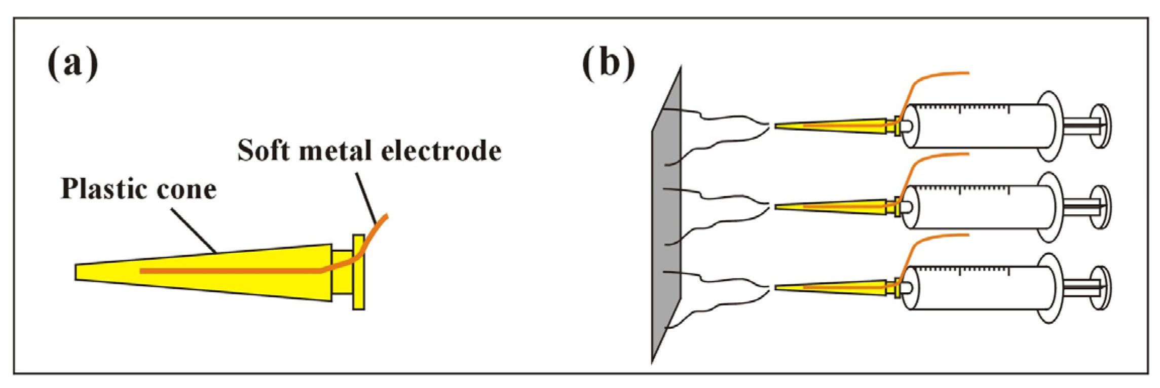
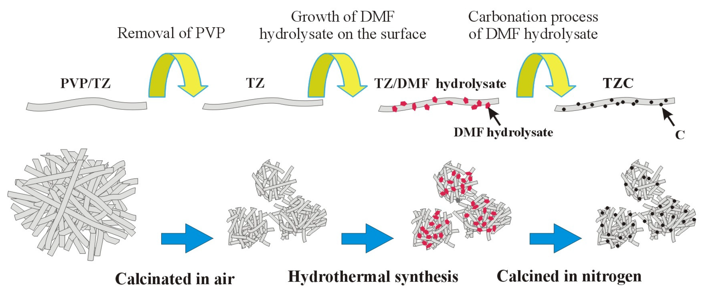
2.2. Synthesis of Zn-Doped TiO2 Nanofiber Film

To prevent the hydrolysate of tetrabutyl titanate from clogging the nozzle during the electrospinning process, the nozzle was modified, as shown in Figure 1. The plastic conical nozzle had a larger diameter than the needle to improve clogging, while the soft metal wire replaced the metal needle as the electrode. Compared to metal needles, which could easily react chemically with acid, plastic nozzles were resistant to acid corrosion, so they didnot contaminate the electrospinning solution. Conical shape facilitated the flow of the solution in the nozzle. To improve efficiency, multi-electrospinning nozzles were used for electrospinning.
To remove water from crystallization, zinc acetate dihydrate (Zn(CH3COO)2·2H2O) was dried at 100 °C for 1 h. Tetrabutyl titanate (Ti(OC4H9)4) was used as a TiO2 precursor, and ethanol absolute (C2H6O) was used as a solvent. Glacial acetic acid had to be used as part of the solvent to inhibit the hydrolysis of the tetrabutyl titanate. A solvent consisting of 4.0 mL of glacial acetic acid and 40.0 mL of absolute ethanol was added to a flask with a lid. Then, 4.0 mL of tetrabutyl titanate and 0.16 g of zinc acetate (Zn(CH3COO)2) were dissolved in the solvent and subsequently stirred for 10 min until it became a homogeneous solution. To avoid agglomeration, 3.2 g of polyvinyl pyrrolidone powder (PVP) was slowly poured into the above solution with stirring. Then, the mixture was stirred for 5 h to dissolve all the PVP to form a homogeneous and stable pale yellow solution at room temperature. For comparison, the reference sample (pure TiO2) was synthesized by the same method.
The above 2 mL solution was placed in an 8 mL syringe with a plastic nozzle for electrospinning. The receiver of the nanofiber film was a piece of aluminum foil taped to a stainless steel plate, which was connected to the negative terminal of a high-voltage power supply. The electrostatic spinning voltage was set to a positive voltage +10 kV and a negative voltage −10 kV. The distance was about 10 cm from the aluminum foil to the nozzle tip. The nanofibers formed a white film containing PVP on the aluminum foil. The electrospun Zn-doped TiO2 and pure TiO2 nanofiber films were calcined in the air. The rate of calcination temperature rise was 25 °C/h until the heating was stopped at 500 °C, then held for 1 h to remove PVP, followed by cooling naturally to room temperature. The large film was broken into smaller films by calcination. Pure TiO2 and Zn-dopedTiO2nanofiber films were denoted as T0 and TZ, respectively.

2.3. Loading of C onto Zn-Doped TiO2 Photocatalyst

C was loaded onto Zn-dopedTiO2nanofiber film using hydrothermal and calcined methods. Next, 0.1 g of TiO2 or Zn-doped TiO2 nanofiber film was dispersed into 30 mL of absolute ethanol and deionized water (1:2 v/v) solution. Then, 10 mL DMF was added to the above system together with 2 mL of acetic acid. The obtained mixture was placed in a stainless steel hydrothermal reactor, which had a Teflon-lined vessel with a lid. T0 and TZ samples were hydrothermally treated at 180 °C for 24 h. To remove excess interferences in the hydrothermal solution, the precipitates were washed 6 times with deionized water after the hydrothermal treatment. Finally, the obtained precipitates were calcined in nitrogen at 400 °C for 1 h. C was based on TiO2 and Zn-doped TiO2 nanofiber films denoted as TC and TZC, respectively. Figure 2 further illustrates the preparation method and process of TZC composite nanofiber film.

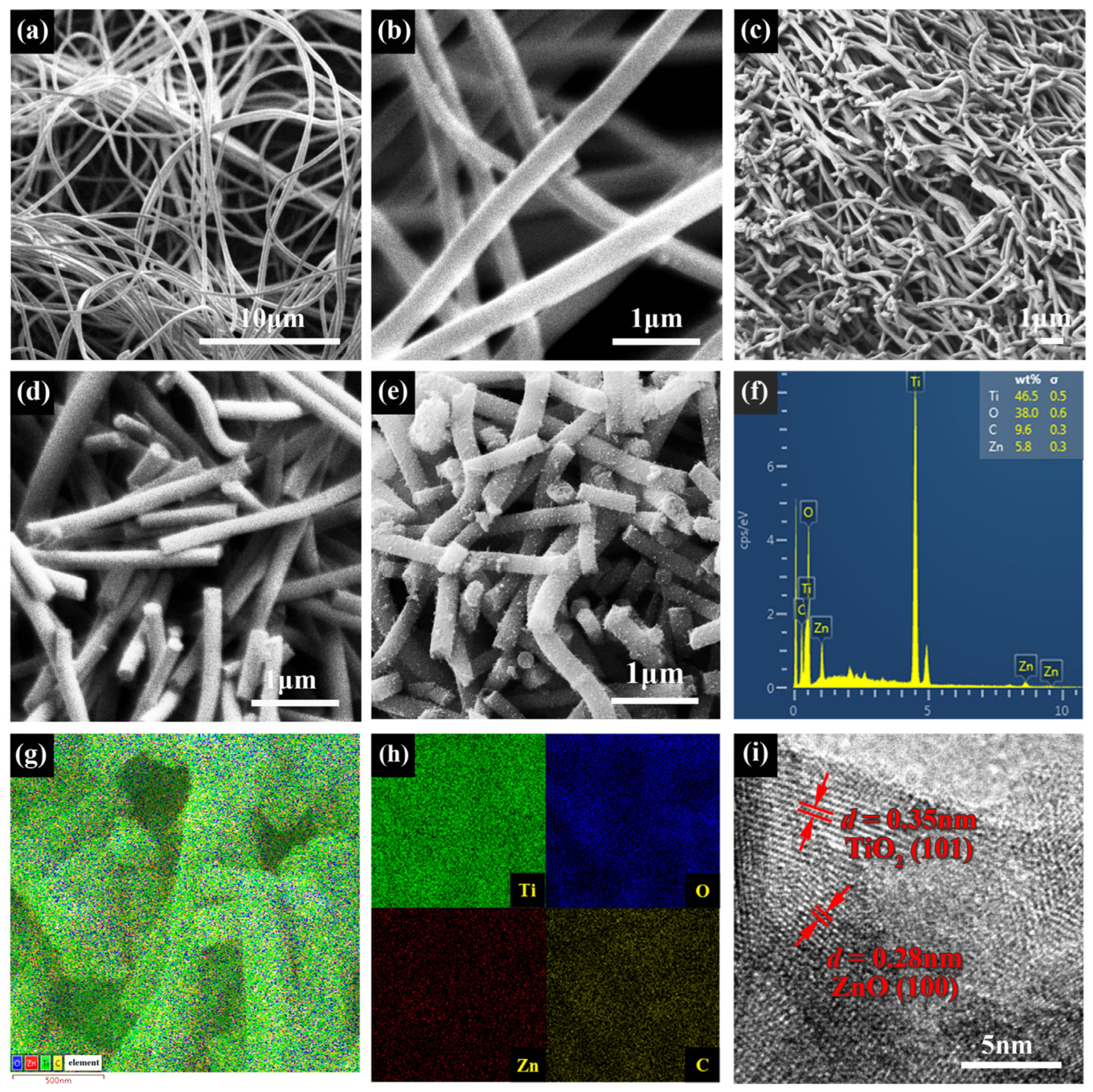
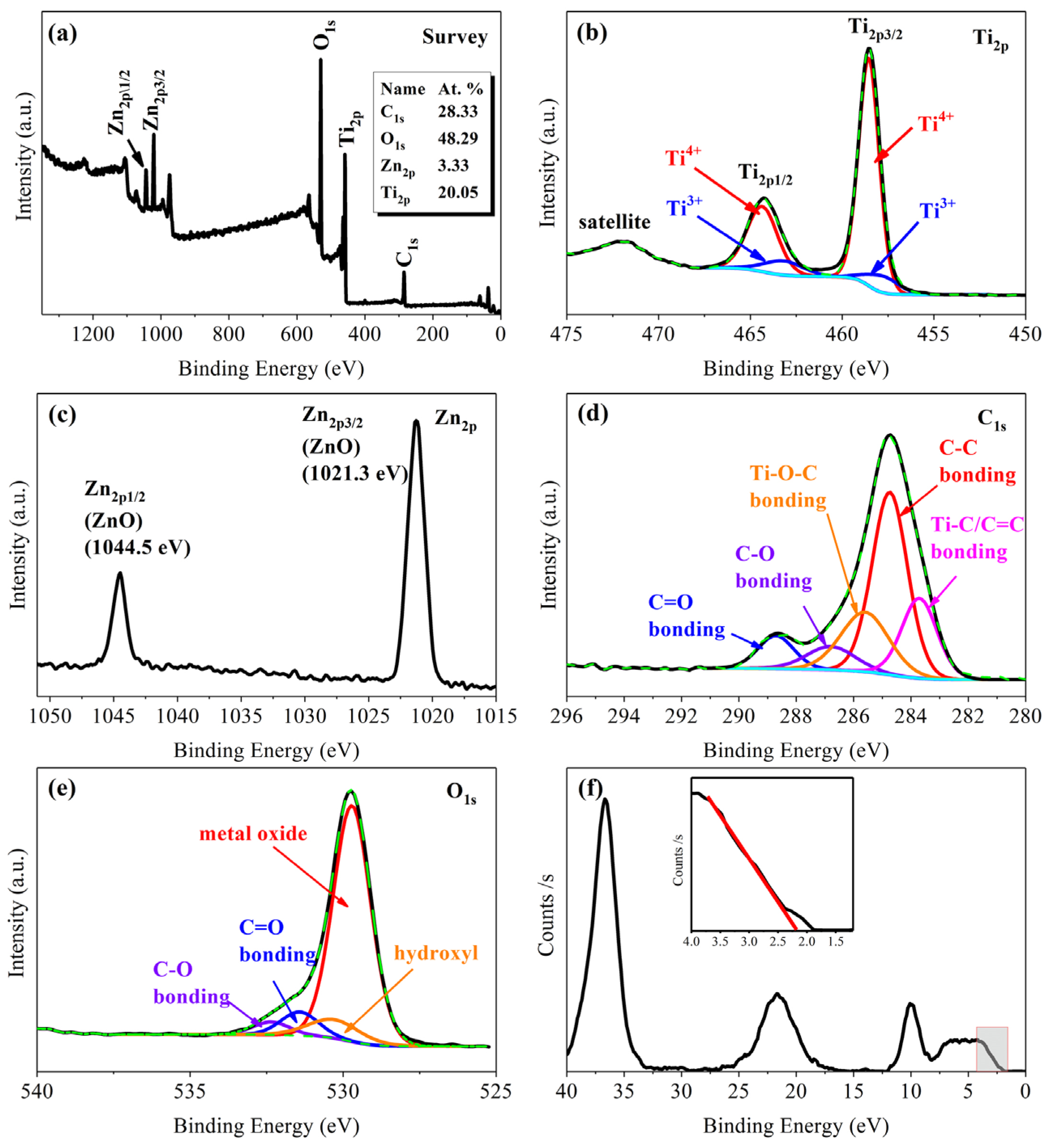
2.4. Characterization

All sample characterization methods, equipment, product models and countries of production are shown in Table 1.
The morphological characteristics of the composite nanofiber film were elucidated by SEM analysis equipped with EDS. TEM and HR-TEM observations were carried out at an acceleration voltage of 200 kV.
The structure and crystal phase were analyzed by XRD with Cu Kα radiation. The X-ray tube operated at a voltage of 40 kV and produced a wavelength of 0.1542 nm. XRD scanned all samples 2θ in the angular range of 20–80°, while the angular speed was 6°/min. The Raman spectra were conducted with an excitation of 325 nm laser light.
Chemical states of elements were accomplished by XPS. Al-Kα irradiation was used in the test.
Optical absorption properties were detected by UV-Vis DRS with BaSO4 as a reference in the scanning range of 200–800 nm. FS were detected with a maximum excitation wavelength of 300 nm. The scanning wavelength range was 330–520 nm.

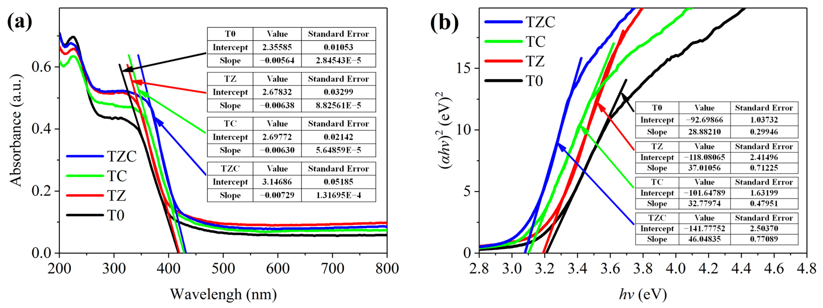
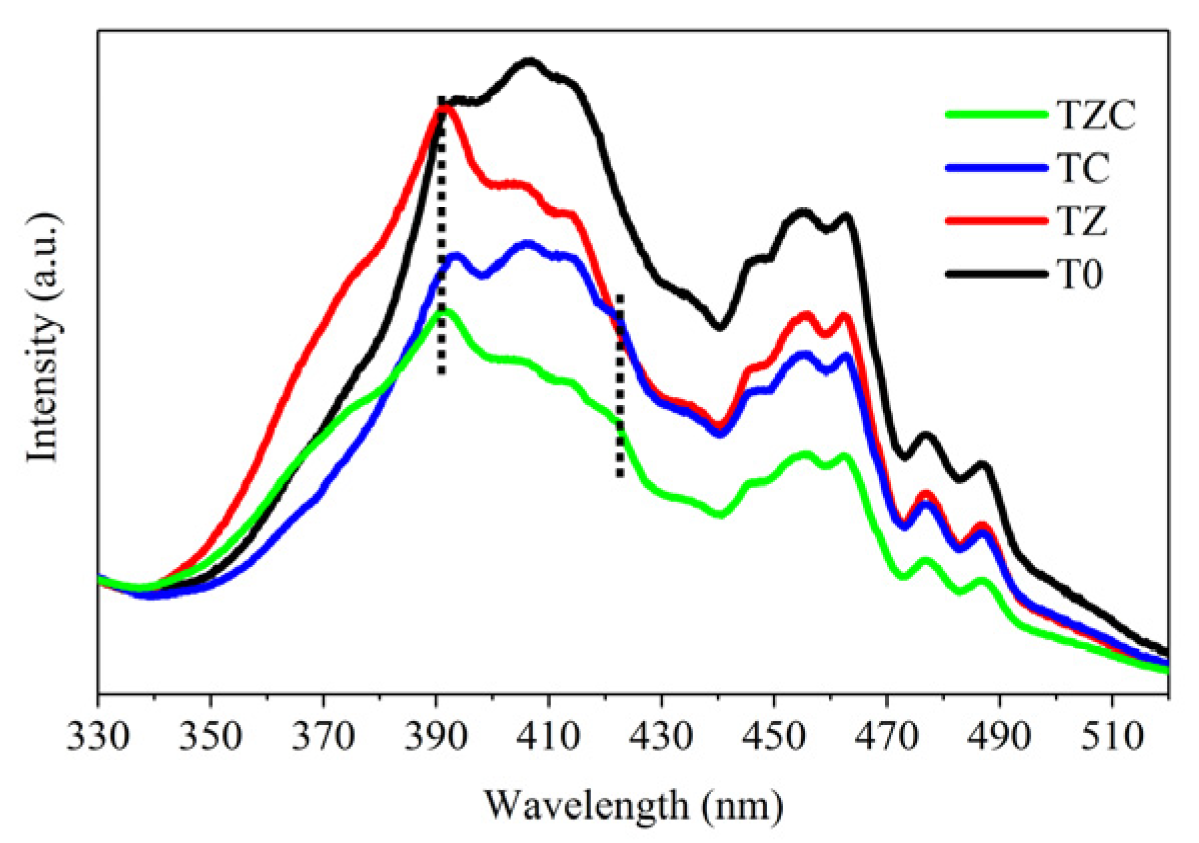
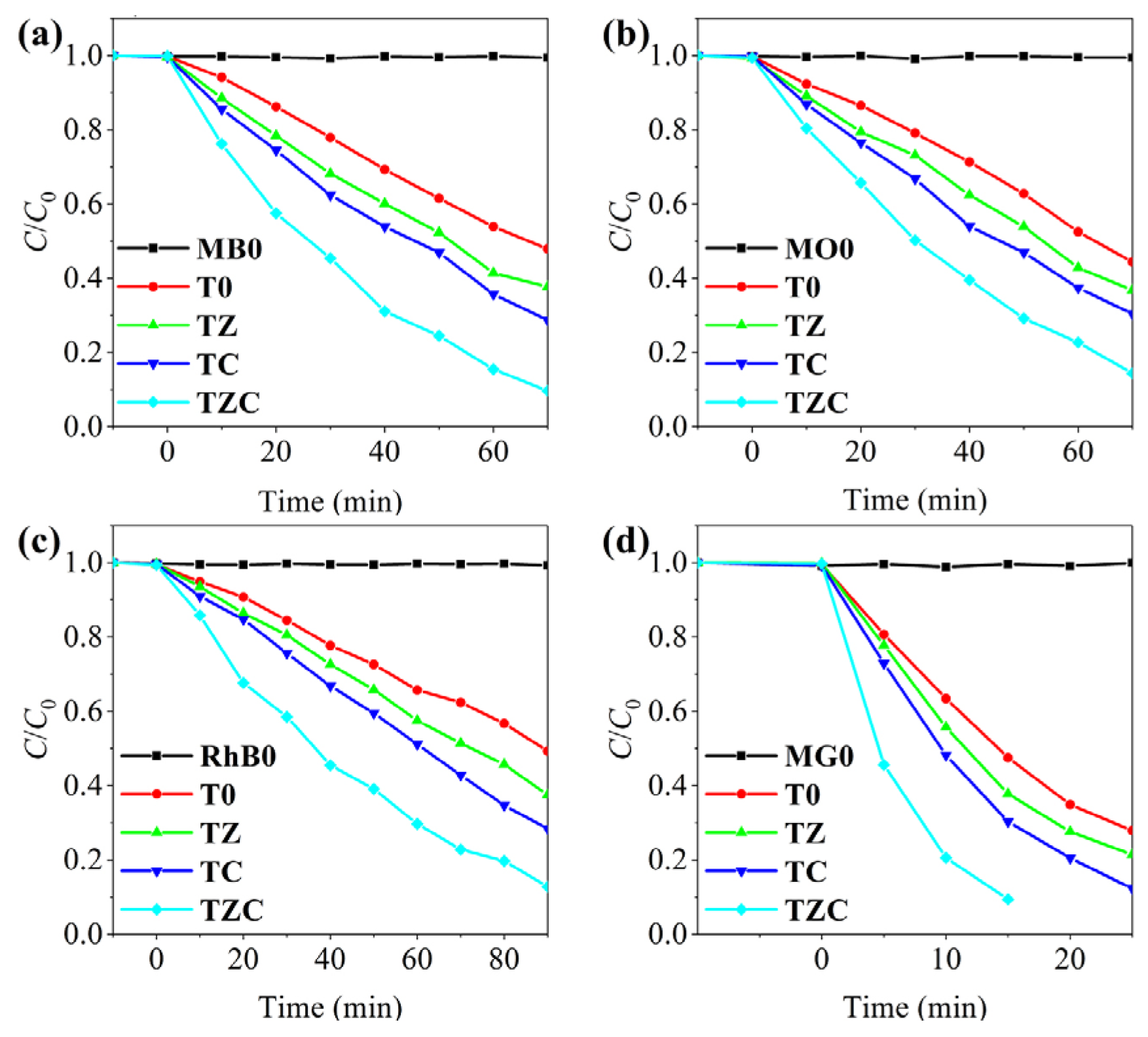
2.5. Photocatalytic Activity

Photodegradation experiments were conducted to evaluate the photocatalytic activity of the prepared nanofiber films. The four organic dyes used as simulated pollutants for the experiments were methylene blue (MB), methyl orange (MO), rhodamine B (RhB) and malachite green (MG). First, 50 mg of nanofiber film (T0, TZ, TC or TZC) was dispersed into 50 mL of MB, MO, RhB or MG solution (10 mg/L). A catalyst content of 1 g/L in the dye was the best compromise for an optimal kinetic study. To eliminate the effect of adsorption, each nanofiber film was stirred continuously in the dark for 10 min to maintain adsorption–desorption equilibrium. The temperature was maintained at 30 ± 2 °C using a thermostatic bath. The pH was the natural pH of the dye solutions. The mixtures were irradiated with a 350 W Xe lamp used as the simulated sunlight. At intervals of 10 min or 5 min, 3 mL of organic dye was collected and centrifuged to separate the solid nanofiber film from the solution quickly. The clear solutions were analyzed by a spectrophotometer to measure the residual concentration. After the photocatalytic experiment, the photocatalyst was recovered by precipitation. The centrifuged and precipitated photocatalysts were combined for the next cycle of experiments after being washed and dried. The same volume of organic dye was used for each cycling experiment. The reusability of C-modified Zn-doped TiO2 was examined by five consecutive cycles in photocatalytic degradation.

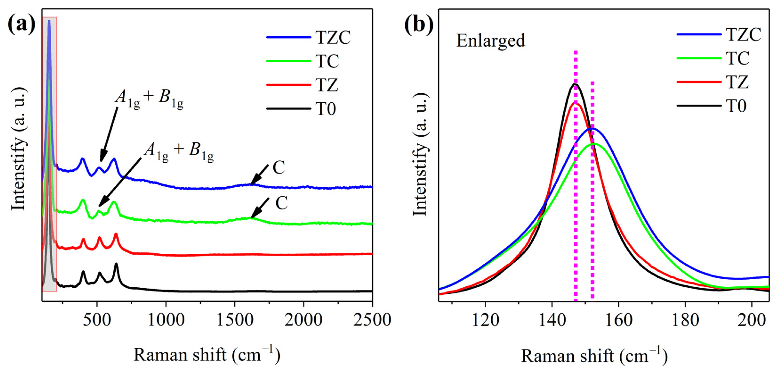
3. Results and Discussion

To observe the lattice and the morphology of nanofiber films, TEM and SEM with the corresponding EDS spectra were used. To increase the electrical conductivity, the samples for SEM were coated with Pt. As shown in Figure 3a,b, the prepared PVP/TZ nanofibers exhibit relatively smooth surfaces and homogeneous one-dimensional structures with diameters ranging from 200 to 250 nm. As shown in Figure 3c,d, the diameters of nanofibers range from 150 to 200 nm after calcination at 500 °C due to the removal of PVP. After loading the C nanostructures onto the TZ nanofibers, the nanofibers were no longer smooth. The C nanospheres were uniformly loaded onto each nanofiber without aggregation, which indicated that a hierarchical heterogeneous structure was successfully constructed, as shown in Figure 3e. In addition, the EDS spectra from the corresponding SEM images indicate that the TZC nanofiber filmare composed of O, Ti, C and Zn elements, as shown in Figure 3f. To strengthen the evidence, elemental mappings were investigated to identify the spatial distributions of O, Ti, C and Zn in the heterojunction, as shown in Figure 3g,h. Obviously, Zn and C were uniformly distributed in the composite nanofiber film, further indicating that C was successfully loaded onto the surface of TZ nanofibers. An HRTEM image was used to further study the microstructure information of the TZC heterojunction. As shown in Figure 3i, crystal lattice fringes with d-spacing of 0.35 and 0.28 nm in HRTEM image are assigned to the lattice plane of anatase TiO2 (101) and ZnO (100).
Figure 4 presents the XRD patterns. All samples reveal a typical anatase TiO2 (JCPDS 73-1764) with obvious characteristic peaks at approximately 25.3°, 38.1°, 48.1°, 54.6° and 62.9°, which are ascribed to (101), (004), (200), (105) and (204) crystal planes, respectively. All the diffraction peaks are sharp, indicating excellent crystallinity because of the proper calcination temperature. Moreover, a clear indication of the presence of ZnO (JCPDS 36-1451) comes from two peaks located at 31.1° and 36.3°, ascribable to (100) and (101) crystal planes in the TZ and TZC samples, respectively. Due to the low content of ZnO, the ZnO peaks are weaker than the TiO2 peaks. This indicates that a part of Zn formed in the ZnO crystal structure instead of entering the TiO2 lattice, and the ZnO crystal is tightly attached to the TiO2 octahedral crystal both internally and on the surface with PVP removal during calcination. As shown in Figure 4b, the X-ray diffraction peaks of the an atase crystal plane (101) in TZ and TZC are slightly shifted toward a lower diffraction angle with the Zn-doped TiO2 compared to T0. This finding suggests that similar ionic radii of dopant Zn (the radius of the Zn2+ ion in the oxide is 0.074 nm) and TiO2 (the radius of the Ti4+ ion in the oxide is 0.068 nm) led to lattice distortion of the anatase structure by another part of Zn entering the lattice of TiO2 [37,38]. These two ways of Zn entering the TiO2 nanofibers are present simultaneously. Crystallite size (D), dislocation density (ρ) and lattice strain (ε) were calculated by the following equations [39]:
D = Kλ/(βcosθ),
ρ = 1/D2,
ε = βcosθ/4,
where λ is the X-ray wavelength, β is FWHM, θ is the diffraction angle, K is a constant 0.9. Table 2 shows a comparison of the crystal microstructures. C and Zn entering the TiO2 lattice changed microstructure, with TZC being the most pronounced. The increased ρ and ε make the crystals more disordered and more defects, which helps to improve the photocatalytic efficiency. No characteristic peaks attributed to C were detected.
Raman spectroscopy is the process of interaction between light and chemical bonds inside materials, which is closely related to the vibrational energy level of materials, especially nanomaterials. Each spectral peak corresponds to a specific chemical bond vibration, which corresponds to information about the material crystal concentration, structure, deformation and defects.
Figure 5a shows the Raman of all nanofiber films. The typical Raman shifts of TiO2 are obtained in all the samples. The Raman shifts at approximately 147 cm−1, 399 cm−1, 519 cm−1 and 637 cm−1 are attributed to Eg, B1g, A1g + B1g, and Eg modes of the anatase TiO2, respectively [40,41,42]. The A1g + B1g mode peak at 519 cm−1 and the Eg mode peak at 147 cm−1 are caused by the Ti-O bond bending and stretching vibrations, respectively [43]. A1g + B1g mode peaks of C-modified TC and TZC are significantly weaker compared to T0 and TZ, which indicates that the bending vibrations of Ti-O bond are altered due to the entry of C into the TiO2 lattice. To further explore the effect of C and Zn on the Raman spectra of TiO2 nanofibers, the strongest peaks are enlarged in Figure 5b. It is seen that the strongest peak positions of TC and TZC are slightly shifted to a higher wavenumber compared with T0 and TZ. The shift of the vibrational peaks indicated that C was successfully loaded onto TiO2 and entered the lattice, leading to distortion. The weakening of the TC and TZC vibrational peaks is attributed to the black C covering the surface of nanofibers, blocking the Raman scattering of the laser. The increased FWHM of TC and TZC vibrational peaks indicates that the loading of C leads to poor crystallinity of anatase and suitable crystal defects, which are beneficial for photocatalytic reactions. At the peak, 1599 cm−1 is attributed to the G-band of graphite exhibiting ordered carbon atoms in TC and TZC samples [44,45]. The G-band is formed by the stretching vibration of all sp2 atoms in the carbon ring or long chain under incident light. This indicates that the presence of a large amount of C in the form of graphite on the surface of the nanofibers can improve the conductivity of the TiO2 surface, thus facilitating the transfer of photogenerated carriers to the organic dye surface. The D-band representing the disordered C is not found. This does not represent the absence of disordered graphite. It has been reported that the D-band decreases in intensity with increasing energy of the incident light wavelength [46]. The D-band may not be detected when the graphite content is relatively low, and the higher energy 325 nm wavelength is used in the test. The above analysis illustrates the existence of TiO2 and C. Unfortunately, there was no peak of ZnO, probably due to the low doping content or the blocking of surface C, but the construction of ZnO was successfully observed in XRD and TEM.
XPS was applied to elucidate the presence of elements and their surface electronic states on TZC nanofiber film. The full survey of XPS spectra shows that TZC nanofibers are composed of Ti, Zn, C and O elements, consistent with the EDS, as shown in Figure 6a. Although XPS was a semi-quantitative measurement, the percent content of the element was calculated based on the peak area and the sensitivity impact factor of the instrument. The atomic percentages of C, O, Zn and Ti were calculated from the C1s, O1s, Zn2p and Ti2p curves to be 28.33%, 48.29%, 3.33% and 20.05%, respectively. C blocks a part of the surface of the TiO2 nanofibers exposed to X-rays, resulting in a lower content of Ti and a higher content of C in the sample. The sample is easily contaminated by C of air, due to the way XPS works. To estimate the percentage of modified C, the percentage of atomic number of C in EDS was calculated as 18.89%. Thus, C from the air accounts for 9.44%. In Figure 6b, the high-resolution spectra of Ti2pshows peaks at 471.6, 464.2 and458.3 eV, corresponding to Ti2p satellite, Ti2p1/2 and Ti2p3/2, respectively [47,48]. The inter-peak distances of Ti2p1/2 and Ti2p3/2 at 5.9 eV indicates that the element Ti is present in the nanofibers in the form of crystals of TiO2 [49]. To fit the Gaussian components perfectly, the broad Ti2p3/2 and Ti2p1/2 peaks were decomposed into two peaks separated by about 1 eV. The main peaks at 458.5 eV and 464.4 eV are attributed to ion Ti4+, while the minor peaks at 457.7 eV and 463.2 eV are assigned to ion Ti3+ [50,51]. The presence of a few ionic Ti3+ molecules on the surface of TiO2 was reported; moreover, XPS analysis was consistent with the study. The presence of ionic Ti3+ leads to weak absorption of visible light in the composite nanofibers, leading to absorption edge redshift (consistent with UV), which is beneficial for improving the photocatalytic efficiency [52]. In Figure 6c, the high-resolution spectra of Zn2p shows peaks at 1021.3 and 1044.3 eV for Zn2p3/2 and Zn2p1/2, respectively, indicating the existence of a Zn2+ oxidation state [53]. The high-resolution C1s spectra are decomposed into five peaks at 283.7, 284.8, 285.6, 286.8 and 288.7 eV, as shown in Figure 6d. XPS C1s shows that C interacts with TiO2 in the form of chemical bonds. The peaks at 283.7 and 285.6 eV represent the Ti-C bond and Ti-O-C group, respectively, exhibiting the chemical bonds formed by C with other elements in TiO2 [54,55]. The chemical bonds formed between C and the elements in TiO2 are beneficial for the transfer of carriers between C and TiO2 [56]. The surface C changes the lattice structure of TiO2, while FS spectra are also observed. The peaks at 284.8, 286.8 and 288.7 eV are attributed to the adventitious carbon of C–C, C–O and C=O bonds, respectively [57]. In Figure 6e, the high-resolution O1s spectra indicates that the peaks at 529.7, 530.3, 531.4 and 532.3 eV are attributed to metal oxide, hydroxyl, C=O and C–O, respectively [58]. From metal oxide, itcan be inferred that TiO2 and ZnO coexist as a heterostructure in TZC. Since the photodegradation efficiency of TiO2 depended on the current carrier distribution at the valence band (VB) potential top and conduction band (CB) potential bottom, XPS valence band spectra were detected to further investigate the bandgap structure. The intersections of the tangents indicate that the VB potential of TZC is 2.186 eV, as shown in Figure 6f.
UV-v is DRS is an effective means of studying the energy band structure of materials [59]. To investigate the optical absorption and heterojunction electronic structures, UV-v is DRS and Tauc’s plots of all samples were applied. All samples exhibit a large slope of the absorption edge curve with a narrow absorption range. Compared with T0, the absorption edges of other samples of incorporated Zn and C are shifted toward a longer wavelength, as seen in Figure 7a. The absorption edge shift indicates charge transfer at the interfaces ofTiO2, ZnO and C. The absorption band edges of all samples range from 417 (T0) to 431 (TZC) nm. Figure 7b shows the Tauc’s plots used to evaluate the band-gap energy. The bandgap of each photocatalyst composite is obtained from the intercept hv axis by plotting the tangent line of the linear part of curve. The bandgapsare (3.210 ± 0.003), (3.190 ± 0.004), (3.101 ± 0.004) and (3.079 ± 0.003) eVfor T0, TZ, TC and TZC, respectively. The narrowing of the band gap due to Zn-doped and C-modified TiO2 nanofibers results in a redshift. Redshift allows lower-energy light to be used for photocatalysis, thereby improving the photocatalytic activity of the photocatalyst. As a result, both modified C and ZnO contribute to the absorbance enhancement of TZC samples. The C-modified and Zn-doped TiO2 nanofiber films also show a redshift in the absorption edges. Besides the effect of heterojunction, when C and Zn enter the TiO2 lattice, causing crystal defects and lattice bending, the redshift of the absorption edge is also induced. Crystal defects are another important factor in reducing the band gap. The redshift of the absorption edge is the result of a combination of two factors. Subsequently, the conduction band (CB) potentials of TZC was calculated according to the following equations:
ECB = EVBEg,
where ECB, EVB and Eg are the conduction band potential, valence band potential and band gap, respectively [60]. According to the valence-band XPS spectra, the EVB values of TZC is 2.186 eV. Consequently, the ECB value is calculated to be (−0.893 ± 0.003) eV for TZC. The samples do not absorb significantly in the visible range, so the activation is borderline among UV and visible edge, and thus without a clear indication of the activation requirements.
Fluorescence spectra (FS) reflect the lifetimes and recombination rates of separated photogenerated holes and electrons [61]. Figure 8 shows the FS of all samples with 300 nm excitation at room temperature. The stronger peaks at about 393 nm are attributed to photogenerated electron-hole pairs recombination in valence and conduction band [62,63]. FS are able to provide information on the oxygen vacancies of the TiO2 composites and the surface states of the nanofibers [64]. Two weak peaks at 463 and 477 nm are attributed to oxygen vacancy associated with Ti3+ centers and oxygen vacancy with trapped electrons or band edge emission [65]. Moreover, after the ion Zn2+ enters the lattice to replace the ion Ti4+, oxygen vacancies are formed due to the difference in the valence, leading to the absence of oxygen shedding. The peaks of TZ and TZC at 393 nm are stronger than the others compared with T0 and TC, indicating the presence of ZnO. The UV luminescence peak of ZnO is at around 391 nm [66]. A shoulder appears at 423 nm in the ZC and ZTC samples, which may belong to the effect produced by the C entry into the lattice. FS intensity of all samples is attenuated compared to T0, indicating the improvement of the separation and recombination efficiency of photogenerated electron-hole pairs by heterostructure energy level adjustment strategy. When heterojunction structures and C modifications are presented on the surface of the nanofiber film, they change the luminescence characteristics of TiO2. Thus, the TZC heterostructure and crystal defects enhance the photocatalytic activity of the nanofiber film.
As shown in Figure 9, the photodegradation activities of all samples were examined by degradation of simulated pollutant dyes (MB, MO, RhB, MG) in aqueous suspension under simulated sunlight. To investigate the role of photocatalysts, degradation experiments of organic dyes MB, MO, RhB and MG without photocatalysts were tested under light, defined as MB0, MO0, RhB0 and MG0, respectively. As a comparison, the results of the blank experiments showed no significant degradation of all dyes in the absence of photocatalyst, indicating that all dyes were degraded by the photocatalytic reaction of the photocatalyst. C/C0 was used to calculate the photocatalytic efficiency [67]. All dyes’ degradation efficiencies of T0 are very low, only 52.1%, 55.6%, 50.7% and 72.1% for MB (Figure 9a), MO (Figure 9b), RhB (Figure 9c) and MG (Figure 9d) with 70 min, 70 min, 90 min and 25 min reaction, respectively. No degradation of any of the dyes was observed when light or photocatalyst was absent. This indicates that all degradation is attributed to the photocatalytic reaction. The degradation efficiency increases with the entry of C and Zn. TZC exhibits the highest efficiency of degradation with 90.3%, 85.6%, 87.2% and 90.6% for MB, MO, RhB and MG with 70 min, 70 min, 90 min and 15 min reactions, respectively. Among the four dyes, MG was the easiest to degrade and RhB was the most difficult. The photocatalytic degradation of organic pollutant dyes conforms the pseudo-first-order reaction kinetic equation:
ln (C0/C) = kt,
where C0 and C are the initial concentration and the concentration at t of simulated pollutants, respectively; k is the rate constant; t is the reaction time [68]. The corresponding pseudo-first-order reaction kinetic fitted slope lines are displayed, with the highest rate constants for the degradation of all dyes at TZC, in Figure 10. In addition, k values for degradation of all dyes were estimated from the kinetic fitted curves, as shown in Figure 11. To evaluate the standard error of the fitted k values, error bars are added to confirm that the calculated parameters are within the error tolerance. In particular, the activity (k-values) of TZC is3.01, 3.01, 2.36 and 2.89 times as high as T0 for the degradation of MB, MG, MO and RhB, respectively. Notably, the corresponding results are very similar to the trend in the rate constant k. The above results confirm that the photocatalytic improvement of TZC is effective for all dyes. As shown in Figure 12, the reusability and stability of TZC was examined. There is no obvious decline after five cycles with the same catalyst, implying the high stability of TZC nanofiber film. The k values in all cycling experiments were calculated in order to further evaluate the effect of cycling experiments on the photocatalyst activity in Figure 13. The k values shows irregular fluctuations in all dyes, but the variations are in the acceptable range. No significant decrease in k value is found in the cycling experiments, indicating that the photocatalysts have good stability and recyclability.
Figure 14 shows the band gap structure of C-modified Zn-doped TiO2. When the heterojunction is constructed, to balance their Fermi levels, electrons are transferred from ZnO to TiO2 through the interface, leaving positively charged holes, as shown in Figure 14a. As a result, a positively charged electron-depletion layer exists in ZnO and a negatively charged electron accumulation layer exists in TiO2, generating an internal electric field from ZnO to TiO2 at the interface, as shown in Figure 14b. The internal electric field causes band bending of TiO2 and ZnO, as shown in Figure 14c. When TiO2 and ZnO are irradiated by photons exceeding their band gap energy, photogenerated electrons are photoexcited from VB to CB, so the positively charged holes are retained. With the help of the internal electric field and the band bending, photogenerated electrons are transferred from TiO2 to ZnO and holes are transferred from the ZnO to TiO2, achieving the separation and transfer of photogenerated electron-hole pairs at the interface, as shown in Figure 14d. Due to the electron mobility and low band structure of C, photogenerated electrons are forced to move from CB of ZnOor TiO2 to C, which effectively separates and hinders recombination of photogenerated electron-hole pairs during electron transport. To summarize, the enhanced photocatalytic activity is due to the heterojunction reducing the recombination of electron-hole pairs increasing the intensity and range of light absorption by black C.
Figure 15 illustrates the possible TiO2 crystal structure after the entry of Zn and C into the lattice. When Zn2+ enters the TiO2 lattice, oxygen vacancies appear due to the absence of oxygen. Subsequently, photogenerated electrons are transferred by occupying the oxygen vacancies, and thus, these oxygen vacancies become the transport pathway for photogenerated carriers. C is attached to the TiO2 surface by chemical reaction and calcined at high temperature, which provides the opportunity for C to enter the surface lattice. Accompanied by the breakage of the original chemical bond of C during calcination, the thermal motion causes C to enter the TiO2 lattice, possibly due to the close contact with TiO2. After C enters the lattice, it may replace O to form Ti-C bonds or Ti to form covalent bonds with the surrounding oxygen. This effect occurs only on the TiO2 surface because C does not have enough energy to enter the inside of the crystal to form a uniform doping like Zn. This defect helps photogenerated electrons to reach the surface more easily to participate in the photocatalytic reaction. Heterojunction and doping simultaneously change the crystal structure of TiO2, thus improving the photocatalytic efficiency.

4. Conclusions

We have designed and synthesized a novel ternary photocatalytic material of C-modified Zn-dopedTiO2 ternary composite nanofiber film by electrospinning and hydrothermal methods. The optimized ternary composite photocatalyst exhibited the highest degradation efficiency for all organic pollutant dyes. The heterojunction structure among ZnO, TiO2 and C reduce the recombination of electron-hole pairs while providing a pathway for photogenerated electron separation. Moreover, nanofibers have a large specific surface area compared to bulk materials and crystal defects, which benefits its interfacial contact with organic pollutants and photogenerated electron transport. Nanofibers have a faster settling speed and are easily recycled as a small-area film material compared to nanoparticles. Therefore, C-modified Zn-dopedTiO2 composite nanofiber film may be a good candidate for industry photocatalysis application due to its advantages of separation freedom, efficiency and stability.

Author Contributions

Conceptualization, Y.L. and J.H.; methodology, Y.L.; formal analysis, Y.L.; investigation, J.H.; writing—original draft preparation, Y.L.; writing—review and editing, Y.L. and X.Q.; supervision, X.Q.; project administration, Y.L. All authors have read and agreed to the published version of the manuscript.

Funding

This research was funded by the Basic Science Research Foundation of Heilongjiang Province, grant number 2019-KYYWF-1397.

Institutional Review Board Statement

Not applicable.

Informed Consent Statement

Not applicable.

Data Availability Statement

Not applicable.

Conflicts of Interest

The authors declare no conflict of interest.

References

  1. Srivastava, V.; Choubey, A.K. Investigation of adsorption of organic dyes present in wastewater using chitosan beads immobilized with biofabricated CuO nanoparticles. J. Mol. Struct. 2021, 1242, 130749. [Google Scholar] [CrossRef]
  2. Kaushal, S.; Kurichh, P.; Singh, P.P. Novel 3D flower like ZnO/MnV2O6 heterojunction as an efficient adsorbent for the removal of imidacloprid and photocatalyst for degradation of organic dyes in waste water. Polyhedron 2021, 201, 115161. [Google Scholar] [CrossRef]
  3. Gade, R.; Ahemed, J.; Yanapu, K.L.; Abate, S.Y.; Tao, Y.T. Someshwar Pola. Photodegradation of Organic Dyes and Industrial Wastewater in the Presence of Layer-type Perovskite Materials under Visible Light Irradiation. J. Environ. Chem. Eng. 2018, 6, 4504–4513. [Google Scholar] [CrossRef]
  4. Sarani, M.; Joshaghani, A.B.; Najafidoust, A.; Asl, E.A.; Hakki, H.K.; Bananifard, H.; Sillanpaa, M. Sun-light driven photo degradation of organic dyes from wastewater on precipitation Ag2CrO4 over SiO2-aerogel and nano silica. Inorg. Chem. Commun. 2021, 133, 108877. [Google Scholar] [CrossRef]
  5. Sharif, H.M.A.; Mahmood, A.; Cheng, H.Y.; Djellabi, R.; Ali, J.; Jiang, W.J.; Wang, S.; Haider, M.R.; Mahmood, N.; Wang, A.J. Fe3O4 Nanoparticles Coated with EDTA and Ag Nanoparticles for the Catalytic Reduction of Organic Dyes from Wastewater. ACS Appl. Nano Mater. 2019, 2, 5310–5319. [Google Scholar] [CrossRef]
  6. Zhang, X.; Zong, Z.; Zhang, X.; Zhang, D.; Luo, Q.; Bi, C.; Fan, Y. Rational design of three bifunctional MOFs for photocatalysis degradation and selective adsorption of wastewater organic dyes removal. Polyhedron 2020, 191, 114816. [Google Scholar] [CrossRef]
  7. Sarkar, B.; Daware, A.V.; Gupta, P.; Krishnani, K.K.; Baruah, S.; Bhattacharjee, S. Nanoscale wide-band semiconductors for photocatalytic remediation of aquatic pollution. Environ. Sci. Pollut. Res. 2017, 24, 25775–25797. [Google Scholar] [CrossRef] [PubMed]
  8. Khezami, L.; Lounissi, I.; Hajjaji, A.; Guesmi, A.; Assadi, A.A.; Bessais, B. Synthesis and Characterization of TiO2 Nanotubes (TiO2-NTs) Decorated with Platine Nanoparticles (Pt-NPs): Photocatalytic Performance for Simultaneous Removal of Microorganisms and Volatile Organic Compounds. Materials 2021, 14, 7341. [Google Scholar] [CrossRef] [PubMed]
  9. Sabarinathan, M.; Harish, S.; Archana, J.; Navaneethan, M.; Ikeda, H.; Hayakawa, Y. Highly efficient visible-light photocatalytic activity of MoS2 –TiO2 mixtures hybrid photocatalyst and functional properties. RSC Adv. 2017, 7, 24754–24763. [Google Scholar] [CrossRef] [Green Version]
  10. Lai, W.W.; Lin, H.H.H.; Lin, A.Y.C. TiO2 Photocatalytic degradation and transformation of oxazaphosphorine drugs in an aqueous environment. J. Hazard. Mater. 2015, 287, 133–141. [Google Scholar] [CrossRef]
  11. Gholamian, S.; Mousavi, M.; Farokhnia, A.; Hamzehloo, M. Effective and magnetically recoverable TiO2/Fe3O4/AgI nanocomposite for degradation dye pollutants under visible light illumination. J. Mater. Sci-Mater. Electron. 2020, 31, 15546–15557. [Google Scholar] [CrossRef]
  12. Fouzia, A.; Rabah, B. Effect of annealing time on structural and optical proprieties of mercury (Hg+2) doped TiO2 thin films elaborated by sol-gel method for future photo-catalytic application. Optik 2021, 247, 167846. [Google Scholar]
  13. Wu, S.; Li, X.; Tian, Y.; Lin, Y.; Hu, Y.H. Excellent photocatalytic degradation of tetracycline over black anatase-TiO2 under visible light. Chem. Eng. J. 2021, 406, 126747. [Google Scholar] [CrossRef]
  14. Zangeneh, H.; Zinatizadeh, A.A.; Zinadini, S.; Feyzi, M.; Rafiee, E.; Bahnemann, D.W. A novel L-Histidine (C, N) codoped-TiO2-CdS nanocomposite for efficient visible photo-degradation of recalcitrant compounds from wastewater. J. Hazard. Mater. 2019, 369, 384–397. [Google Scholar] [CrossRef] [PubMed]
  15. Hieu, V.Q.; Phung, T.K.; Nguyen, T.Q.; Khan, A.; Doan, V.D.; Tran, V.A.; Le, V.T. Photocatalytic degradation of methyl orange dye by Ti3C2-TiO2 heterojunction under solar light. Chemosphere 2021, 276, 130154. [Google Scholar] [CrossRef] [PubMed]
  16. Khalil, M.; Anggraeni, E.S.; Ivandini, T.A.; Budianto, E. Exposing TiO2 (001) crystal facet in nano Au-TiO2 heterostructures for enhanced photodegradation of methylene blue. Appl. Surf. Sci. 2019, 487, 1376–1384. [Google Scholar] [CrossRef]
  17. Gu, J.; Yu, Y.; Chen, S.; Shi, W.; Wang, Y.; Liao, Y.; Chen, H.; Jiang, F. Heterojunction photocatalyst of cavity shaped Bi2S3/g-C3N4 for bisphenol a degradation: Regulation of internal electric field via assistance of interfacial functional groups. Chem. Eng. J. 2021, 424, 130539. [Google Scholar] [CrossRef]
  18. Kumar, A.; Sharma, S.K.; Sharma, G.; Guo, C.; Vo, D.V.N.; Iqbal, J.; Naushad, M.; Stadler, F.J. Silicate glass matrix@Cu2O/Cu2V2O7 p-n heterojunction for enhanced visible light photo-degradation of sulfamethoxazole: High charge separation and interfacial transfer. J. Hazard. Mate. 2021, 402, 123790. [Google Scholar] [CrossRef]
  19. Eshaq, G.; Wang, S.; Sun, H.; Sillanpää, M. Core/shell FeVO4@BiOCl heterojunction as a durable heterogeneous Fenton catalyst for the efficient sonophotocatalytic degradation of p-nitrophenol. Sep. Purifi. Technol. 2020, 231, 115915. [Google Scholar] [CrossRef]
  20. Gao, X.; Ren, P.G.; Wang, J.; Ren, F.; Dai, Z.; Jin, Y.L. Fabrication of visible-light responsive TiO2@C photocatalyst with an ultrathin carbon layer to efficiently degrade organic pollutants. Appl. Surf. Sci. 2020, 532, 147482. [Google Scholar] [CrossRef]
  21. Kwon, H.; Marques Mota, F.; Chung, K.; Jang, Y.J.; Hyun, J.K.; Lee, J.; Kim, D.H. Enhancing Solar Light-Driven Photocatalytic Activity of Mesoporous Carbon–TiO2 Hybrid Films via Upconversion Coupling. ACS Sustain. Chem. Eng. 2018, 6, 1310–1317. [Google Scholar] [CrossRef]
  22. Aggelopoulos, C.A.; Dimitropoulos, M.; Govatsi, A.; Sygellou, L.; Tsakiroglou, C.D.; Yannopoulos, S.N. Influence of the Surface-to-Bulk Defects Ratio of ZnO and TiO2 on their UV-mediated Photocatalytic Activity. Appl. Catal. B-Environ. 2017, 205, 292–301. [Google Scholar] [CrossRef]
  23. Tekin, D.; Kiziltas, H.; Ungan, H. Kinetic evaluation of ZnO/TiO2 thin film photocatalyst in photocatalytic degradation of Orange G. J. Mol. Liq. 2020, 306, 112905. [Google Scholar] [CrossRef]
  24. El Mragui, A.; Daou, I.; Zegaoui, O. Influence of the preparation method and ZnO/(ZnO+TiO2) weight ratio on the physicochemical and photocatalytic properties of ZnO-TiO2 nanomaterials. Catal. Today 2019, 321–322, 41–51. [Google Scholar] [CrossRef]
  25. Chen, M.; Chu, W. Degradation of antibiotic norfloxacin in aqueous solution by visible-light-mediated C-TiO2 photocatalysis. J. Hazard. Mater. 2012, 219–220, 183–189. [Google Scholar] [CrossRef]
  26. Shim, J.; Seo, Y.S.; Oh, B.T.; Cho, M. Microbial inactivation kinetics and mechanisms of carbon-doped TiO2 (C-TiO2) under visible light. J. Hazard. Mater. 2016, 3061, 133–139. [Google Scholar] [CrossRef]
  27. Kuhn, B.L.; Paveglio, G.C.; Silvestri, S.; Muller, E.I.; Enders, M.S.P.; Martins, M.A.P.; Zanatta, N.; Bonacorso, H.G.; Radke, C.; Frizzo, C.P. TiO2 nanoparticles coated with deep eutectic solvents: Characterization and effect on photodegradation of organic dyes. N. J. Chem. 2019, 43, 1415–1423. [Google Scholar] [CrossRef]
  28. Calzada, L.A.; Castellanos, R.; García, L.A.; Klimova, T.E. TiO2, SnO2 and ZnO catalysts supported on mesoporous SBA-15 versus unsupported nanopowders in photocatalytic degradation of methylene blue. Micropor. Mesopor. Mat. 2019, 285, 247–258. [Google Scholar] [CrossRef]
  29. Liu, R.; Bie, Y.; Qiao, Y.; Liu, T.; Song, Y. Design of g-C3N4/TiO2 nanotubes heterojunction for enhanced organic pollutants degradation in waste water. Mater. Lett. 2019, 251, 126–130. [Google Scholar] [CrossRef]
  30. Thambiliyagodage, C.; Usgodaarachchi, L. Photocatalytic activity of N, Fe and Cu co-doped TiO2 nanoparticles under sunlight. Curr. Res. Green Sustain. Chem. 2021, 4, 100186. [Google Scholar] [CrossRef]
  31. Adhikari, S.P.; Awasthi, G.P.; Kim, H.J.; Park, C.H.; Kim, C.S. Electrospinning directly synthesized porous TiO2 nanofibers modified by graphitic carbon nitride sheets for enhanced photocatalytic degradation activity under solar light irradiation. Langmuir 2016, 32, 6163–6175. [Google Scholar] [CrossRef]
  32. Zhang, Z.; Shao, C.; Li, X.; Wang, C.; Zhang, M.; Liu, Y. Electrospun Nanofibers of p-Type NiO/n-Type ZnO Heterojunctions with Enhanced Photocatalytic Activity. ACS Appl. Mater. Interfaces 2010, 2, 2915–2923. [Google Scholar] [CrossRef] [PubMed]
  33. Pantò, F.; Dahrouch, Z.; Saha, A.; Patanè, S.; Santangelo, S.; Triolo, C. Photocatalytic degradation of methylene blue dye by porous zinc oxide nanofibers prepared via electrospinning: When defects become merits. Appl. Surf. Sci. 2021, 557, 149830. [Google Scholar] [CrossRef]
  34. Ognibene, G.; Cristaldi, D.A.; Fiorenza, R.; Blanco, I.; Cicala, G.; Scirè, S.; Fragalà, M.E. Photoactivity of hierarchically nanostructured ZnO–PES fibre mats for water treatments. RSC Adv. 2016, 49, 42778–42785. [Google Scholar] [CrossRef]
  35. Zhang, P.; Shao, C.; Zhang, Z.; Zhang, M.; Mu, J.; Guo, Z.; Sun, Y.; Liu, Y. Core/shell nanofibers of TiO2 @carbon embedded by Ag nanoparticles with enhanced visible photocatalytic activity. J. Mater. Chem. 2011, 21, 17746–17753. [Google Scholar] [CrossRef]
  36. Tripathi, N.; Akai, T. Structural designing of Zn2SiO4: Mn nanocrystals by co-doping of alkali metal ions in mesoporous silica channels for enhanced emission efficiency with short decay time. RSC Adv. 2021, 11, 36348. [Google Scholar] [CrossRef]
  37. Jaimy, K.B.; Ghosh, S.; Sankar, S.; Warrier, K.G.K. An aqueous sol-gel synthesis of chromium (III) doped mesoporous titanium dioxide for visible light photocatalysis. Mater. Res. Bull. 2011, 46, 914–921. [Google Scholar] [CrossRef]
  38. Ganesh, V.; AlAbdulaal, T.H.; AlShadidi, M.; Hussien, M.S.A.; Bouzidi, A.; Algarni, H.; Zahran, H.Y.; Abdel-wahab, M.S.; Mohammed, M.I.; Yahia, I.S.; et al. Enhancement in the Structural, Electrical, Optical, and Photocatalytic Properties of La2O3-Doped ZnO Nanostructures. Materials 2022, 15, 6866. [Google Scholar] [CrossRef]
  39. Šćepanović, M.J.; Grujić-Brojčin, M.; Dohčević-Mitrović, Z.D.; Popović, Z.V. Characterization of Anatase TiO2 Nanopowder by Variable-Temperature Raman Spectroscopy. Sci. Sinter. 2009, 41, 67–73. [Google Scholar] [CrossRef]
  40. Miao, L.; Tanemura, S.; Toh, S.; Kaneko, K.; Tanemura, M. Fabrication, characterization and Raman study of anatase-TiO2 nanorods by a heating-sol–gel template process. J. Cryst. Growth 2004, 264, 246–252. [Google Scholar] [CrossRef]
  41. Pandya, J.K.; Zhang, Z.; He, L. Surface-Enhanced Raman Spectroscopic Analysis of Anatase Titanium Dioxide Nanoparticles: Investigation of the Key Factors. ChemistrySelect 2021, 6, 5987–5993. [Google Scholar] [CrossRef]
  42. Ohsaka, T.; Izumi, F.; Fujiki, Y. Raman Spectrum of Anatase, TiO2. J. Raman Spectrosc. 1978, 7, 321–324. [Google Scholar] [CrossRef]
  43. Cuesta, A.; Dhamelincourt, P.; Laureyns, J.; Martínez-Alonso, A.; Tascón, J.M.D. Raman microprobe studies on carbon materials. Carbon 1994, 32, 1523–1532. [Google Scholar] [CrossRef]
  44. Ferrari, A.C.; Robertson, J. Interpretation of Raman spectra of disordered and amorphous carbon. Phys. Rev. B 2000, 61, 14095. [Google Scholar] [CrossRef] [Green Version]
  45. Wang, Y.; Alsmeyer, D.C.; McCreery, R.L. Raman Spectroscopy of Carbon Materials: Structural Basis of Observed Spectra. Chem. Mater. 1990, 2, 557–563. [Google Scholar] [CrossRef]
  46. Ismael, M. Enhanced photocatalytic hydrogen production and degradation of organic pollutants from Fe (III) doped TiO2 nanoparticles. J. Environ. Chem. Eng. 2020, 8, 103676. [Google Scholar] [CrossRef]
  47. Pérez-González, M.; Tomás, S.A. Surface chemistry of TiO2-ZnO thin films doped with Ag. Its role on the photocatalytic degradation of methylene blue. Catal. Today 2021, 360, 129–137. [Google Scholar] [CrossRef]
  48. Seddiki, O.; Harnagea, C.; Levesque, L.; Mantovani, D.; Rosei, F. Evidence of antibacterial activity on titanium surfaces through nanotextures. Appl. Surf. Sci. 2014, 308, 275–284. [Google Scholar] [CrossRef]
  49. Chu, D.; Younis, A.; Li, S. Direct growth of TiO2 nanotubes on transparent substrates and their resistive switching characteristics. J. Phys. D Appl. Phys. 2012, 45, 355306. [Google Scholar] [CrossRef]
  50. Kaspar, T.C.; Sushko, P.V.; Bowden, M.E.; Heald, S.M.; Papadogianni, A.; Tschammer, C.; Bierwagen, O.; Chambers, S.A. Defect compensation by Cr vacancies and oxygen interstitials in Ti4+-doped Cr2O3 epitaxial thin films. Phys. Rev. B 2016, 94, 155409. [Google Scholar] [CrossRef] [Green Version]
  51. Xiong, L.B.; Li, J.L.; Yang, B.; Yu, Y. Ti3+ in the Surface of Titanium Dioxide: Generation, Properties and Photocatalytic Application. J. Nanomater. 2012, 2012, 831524. [Google Scholar] [CrossRef] [Green Version]
  52. Adam, R.E.; Alnoor, H.; Pozina, G.; Liu, X.; Willander, M.; Nur, O. Synthesis of Mg-doped ZnO NPs via a chemical low-temperature method and investigation of the efficient photocatalytic activity for the degradation of dyes under solar light. Solid State Sci. 2020, 99, 106053. [Google Scholar] [CrossRef]
  53. Khan, H.; Jiang, Z.; Berk, D. Molybdenum doped graphene/TiO2 hybrid photocatalyst for UV/visible photocatalytic applications. Sol. Energy 2018, 162, 420–430. [Google Scholar] [CrossRef]
  54. Qiu, B.; Zhou, Y.; Ma, Y.; Yang, X.; Sheng, W.; Xing, M.; Zhang, J. Facile synthesis of the Ti3+ self-doped TiO2-graphene nanosheet composites with enhanced photocatalysis. Sci. Rep. 2015, 5, 8591. [Google Scholar] [CrossRef] [Green Version]
  55. Xing, M.; Shen, F.; Qiu, B.; Zhang, J. Highly-dispersed Boron-doped Graphene Nanosheets Loaded with TiO2 Nanoparticles for Enhancing CO2 Photoreduction. Sci. Rep. 2014, 6, 6341. [Google Scholar] [CrossRef] [PubMed] [Green Version]
  56. Abd-Elrahim, A.G.; Chun, D.M. Room-temperature deposition of ZnO-graphene nanocomposite hybrid photocatalysts for improved visible-light-driven degradation of methylene blue. Ceram. Int. 2021, 47, 12812–12825. [Google Scholar] [CrossRef]
  57. Khan, H.; Berk, D. Characterization and mechanistic study of Mo+6 and V+5 codoped TiO2 as a photocatalyst. J. Photoch. Photobio. A 2014, 294, 96–109. [Google Scholar] [CrossRef]
  58. Ganesh, V.; Hussien, M.S.A.; Shaik, U.P.; Ade, R.; Mohammed, M.I.; AlAbdulaal, T.H.; Zahran, H.Y.; Yahia, I.S.; Abdel-wahab, M.S. Impact of Mo-Doping on the Structural, Optical, and Electrocatalytic Degradation of ZnO Nanoparticles: Novel Approach. Crystals 2022, 12, 1239. [Google Scholar] [CrossRef]
  59. Yulizar, Y.; Eprasatya, A.; Apriandanu, D.O.B.; Yunarti, R.T. Facile synthesis of ZnO/GdCoO3 nanocomposites, characterization and their photocatalytic activity under visible light illumination. Vacuum 2021, 183, 109821. [Google Scholar] [CrossRef]
  60. Yan, J.H.; Zhu, Y.R.; Tang, Y.G.; Zheng, S.Q. Nitrogen-doped SrTiO3/TiO2 composite photocatalysts for hydrogen production under visible light irradiation. J. Alloy. Compd. 2009, 472, 429–433. [Google Scholar] [CrossRef]
  61. El Mragui, A.; Logvina, Y.; Pinto da Silva, L.; Zegaoui, O.; Esteves da Silva, J.C.G. Synthesis of Fe-and Co-Doped TiO2 with Improved Photocatalytic Activity Under Visible Irradiation Toward Carbamazepine Degradation. Materials 2019, 12, 3874. [Google Scholar] [CrossRef] [Green Version]
  62. Domínguez-Jaimes, L.P.; Cedillo-González, E.I.; Luévano-Hipólito, E.; Acuña-Bedoya, J.D.; Hernández-López, J.M. Degradation of primary nanoplastics by photocatalysis using different anodized TiO2 structures. J. Hazard. Mater. 2021, 413, 125452. [Google Scholar] [CrossRef] [PubMed]
  63. Lei, Y.; Zhang, L.D. Fabrication, characterization, and photoluminescence properties of highly ordered TiO2 nanowire arrays. J. Mater. Res. 2001, 16, 1138–1144. [Google Scholar] [CrossRef]
  64. Khan, H.; Swati, I.K. Fe3+-doped Anatase TiO2 with d-d Transition, Oxygen Vacancies and Ti3+ Centers: Synthesis, Characterization, UV/vis Photocatalytic and Mechanistic Studies. Ind. Eng. Chem. Res. 2016, 55, 6619–6633. [Google Scholar] [CrossRef]
  65. Raoufi, D. Synthesis and photoluminescence characterization of ZnO nanoparticles. J. Lumin. 2013, 134, 213–219. [Google Scholar] [CrossRef]
  66. Zyoud, S.H.; Yahia, I.S.; Shahwan, M.; Zyoud, A.H.; Zahran, H.Y.; Abdel-wahab, M.S.; Daher, M.G.; Nasor, M.; Makhadmeh, G.N.; Hassan, N.; et al. Fast and Excellent Enhanced Photocatalytic Degradation of Methylene Blue Using Silver-Doped Zinc Oxide Submicron Structures under Blue Laser Irradiation. Crystals 2023, 13, 229. [Google Scholar] [CrossRef]
  67. Hussien, M.S.A.; Bouzidi, A.; Abd-Rabboh, H.S.M.; Yahia, I.S.; Zahran, H.Y.; Abdel-wahab, M.S.; Alharbi, W.; Awwad, N.S.; Ibrahim, M.A. Fabrication and Characterization of Highly Efficient As-Synthesized WO3/Graphitic-C3N4 Nanocomposite for Photocatalytic Degradation of Organic Compounds. Materials 2022, 15, 2482. [Google Scholar] [CrossRef]
  68. Petrella, A.; Spasiano, D.; Cosma, P.; Rizzi, V.; Race, M.; Mascolo, M.C.; Ranieri, E. Methyl Orange Photo-Degradation by TiO2 in a Pilot Unit under Different Chemical, Physical, and Hydraulic Conditions. Processes 2021, 9, 205. [Google Scholar] [CrossRef]
Figure 1. Basic set-up for (a) anti-clogging nozzle; (b) multi-electrospinning nozzles.
Coatings 13 00647 g001
Figure 2. Preparation process of composite nanofiber film materials.
Coatings 13 00647 g002
Figure 3. SEM images of (a) PVP/TZ; (b) PVP/TZ enlarged; (c) TZ;(d) TZ enlarged; (e) TZC; (f) EDS spectra of TZC; (g) EDS mapping of TZC; (h) elemental distribution; (i) HRTEM image of TZC.
Coatings 13 00647 g003
Figure 4. (a) XRD patterns of all samples; (b) crystal plane (101) enlargedimage.
Coatings 13 00647 g004
Figure 5. (a) Raman spectra of all samples; (b) enlarged image of the strongest peaks for all samples.
Coatings 13 00647 g005
Figure 6. XPS spectra of TZC (a) survey; (b) Ti2p; (c) Zn2p; (d) C1s; (e) O1s; (f) valence.
Coatings 13 00647 g006
Figure 7. (a) UV-vis DRS; (b) Tauc’s plots of all samples.
Coatings 13 00647 g007
Figure 8. Fluorescence spectra (FS) of all samples.
Coatings 13 00647 g008
Figure 9. Photocatalytic degradation efficiency of (a) MB; (b) MO; (c) RhB; (d) MG.
Coatings 13 00647 g009
Figure 10. The corresponding pseudo-first-order reaction kinetic fitted curves (a) MB; (b) MO; (c) RhB; (d) MG.
Coatings 13 00647 g010
Figure 11. The kinetic values of all samples for the degradation of (a) MB; (b) MO; (c) RhB; (d) MG.
Coatings 13 00647 g011
Figure 12. Recycling test of the TZC for the degradation of (a) MB; (b) MO; (c) RhB; (d) MG.
Coatings 13 00647 g012
Figure 13. k of recycling test (a) MB; (b) MO; (c) RhB; (d) MG.
Coatings 13 00647 g013
Figure 14. Schematic diagram of the possible mechanism for the charge-transfer process in the heterojunction (a) ZnO/TiO2 heterojunction; (b) electric field at the interface of ZnO/Ti2O; (c) band bending of ZnO and TiO2; (d) ZnO/TiO2/C heterojunction.
Coatings 13 00647 g014
Figure 15. Schematic diagram of possible crystal defects.
Coatings 13 00647 g015
Table 1. Information of characterization methods, equipment, product models and countries.
Characterization MethodsEquipmentProduct ModelCountry
Scanning electron microscopy (SEM)
Energy-dispersive X-ray spectrometer (EDS)
Field-emission scanning electron microscopeJeol JSM-7800FJapan
Transmission electron microscopy (TEM)
High-resolution transmission electron microscopy (HR-TEM)
Field-emission transmission electron microscopeJeol JEM-2100FJapan
X–ray diffraction (XRD) patternsX-ray powder diffractometerBruker D8 AdvanceGermany
Raman spectraMicroscopic confocal Raman spectrometerRenishaw inViaUK
X–ray photoelectron spectroscopy (XPS)X-ray photoelectron spectrometerThermoEscalab 250 Xi USA
UV-Vis diffuse reflectance spectroscopy (UV-Vis DRS)UV-Vis spectrophotometerShimadzu UV-3600 Japan
Fluorescence spectra (FS)Fluorescence spectrophotometerGangdong F-380China
Table 2. Comparison of microstructure of all samples.
SamplesD (nm)ρ (1/nm)2Ε
T0190.0030.0018
TC140.0050.0024
TZ100.0090.0034
TZC70.020.0050
Disclaimer/Publisher’s Note: The statements, opinions and data contained in all publications are solely those of the individual author(s) and contributor(s) and not of MDPI and/or the editor(s). MDPI and/or the editor(s) disclaim responsibility for any injury to people or property resulting from any ideas, methods, instructions or products referred to in the content.

