Article

Surface Modification of Carbon Nanotubes in Silicone–Polyurethane for Improved Mechanical and Anticorrosion Properties

1
College of Chemistry and Chemical Engineering, Shanghai University of Engineering Science, LongTeng Road 333, Shanghai 201620, China
2
T&H Chemicals Co., Ltd., Tangxi Industrial Zone, Quanzhou 362011, China
3
Division of Biotechnology, College of Environmental and Bioresource Sciences, Chonbuk National University, Iksan 570-752, Republic of Korea
*
Authors to whom correspondence should be addressed.
These authors contributed equally to this work.
Coatings 2023, 13(3), 634; https://doi.org/10.3390/coatings13030634
Submission received: 31 January 2023 / Revised: 4 March 2023 / Accepted: 13 March 2023 / Published: 17 March 2023

Abstract

:
Carbon nanotubes (CNT) were dispersed into homemade silicone–polyurethane (SPU) resin in order to enhance their mechanical and anticorrosion ability. Before mixing with SPU, CNT were modified by four different approaches to improve their dispersion in SPU, and the surface of CNT were covered by SiO2–TiO2 nanoparticles, -NH2 groups, epoxy groups or isocyanate groups, respectively. The structures of the modified CNTs were checked by XRD, FTIR, and SEM. After being dispersed in SPU to form a composite coating, the one with SiO2–TiO2 nanoparticles modified CNT exhibited the best mechanical properties and chemical resistance (low water absorption), and its corrosion current density (icorr) was only 9.246 × 10⁻⁹ A cm2, which is four orders of magnitude lower than the icorr value of the coating with unmodified CNT (1.599 × 10⁻⁵ A/cm2). This may be because the covered SiO2–TiO2 nanoparticle increased the roughness of the CNT surface, which can improve their dispersion in SPU resin.

1. Introduction

Polyurethane (PU) is a multifunctional polymer material with good tensile strength, flexibility, elasticity, resistance to chemical resistance and excellent substrate adhesion; thus, it has a wide range of applications in adhesives, coatings, foam, film, bionic materials and other fields [1,2,3,4]. Nevertheless, the disadvantages of PU materials still have limitations for their application, such as poor thermal capability, poor weather ability, and flammability. The silicone modified polyurethane (SPU) can bring the excellent advantages of silicone into the system to enhance PU resin’s weather ability, flexibility and water repellency [5,6,7]. Moreover, in order to endow the PU-based material with additional functions, inorganic nanomaterials are usually selected to form composites with PU, such as carbon nanotubes, graphene or TiO2 nanoparticles [8,9,10]. By adding a small part of inorganic nanomaterials, PU performance, such as the anticorrosion and mechanical strength, can be significantly improved [11,12,13,14].
Multi-walled carbon nanotube (CNT) is a kind of famous nanofillers for polymers. CNT have excellent properties, such as high electrical conductivity, thermal conductivity and chemical stability [15,16,17]. Through the formation of hydrogen bonds or strong van der Waals force between PU groups and CNT, different properties can be provided for PU composites [18]. However, the high specific surface area and high surface energy of CNT tend to agglomerate, limiting the performance efficiency of CNT in the PU matrix [19]. To overcome this bottleneck, many approaches have been adopted to improve the arrangement and dispersion of CNTs, e.g., by in-situ polymerization [20], surface modifications [21] or chemical functionalization [22]. The previous literature has shown that CNTs with these treatments can realize excellent performance when combined with PU. Among the above treatment approaches, surface modification is one of the most effective methods, which can be achieved through a variety of ways, such as surface amination [23,24,25], carboxylation, silylation and carbonylation [26,27,28]. In addition, different surface modifications of CNTs can bring different effects to the composites. He et al. modified Fe2O3-CNTs hybrid materials with a silane coupling agent (KH560, with an epoxy group), and the prepared Fe2O3-CNTs/epoxy resin composite coatings exhibited enhanced mechanical properties and corrosion resistance [14]. Li et al. functionalized hydroxylated CNTs with 3-aminopropyltriethoxysilane via a silylation reaction, and silanes were covalently attached to the surface of CNTs. The modified CNTs showed better dispersion and strong interfacial adhesion to the PU matrix, improving the elongation, hydrophobicity and electrical conductivity of the PU material [29,30]. Although the modification of carbon nanotube has been proven to have positive effects in PU composites, there were normally only one or two modifications for CNTs in each PU system. Besides, research seldom focuses on the effect of CNT in the SPU system. As the properties of the SPU system are somehow different from the PU resin, it is meaningful to figure out the effects of different CNT modification approaches in the SPU system, which may provide the efficiency profiles of surface modification for CNTs application.
In this work, commercial carboxylated multi-walled carbon nanotubes (CNT) were adopted, and different surface modifications of CNT were carried out to check their influences on the performance of the SPU substrate. CNT was modified with amino groups, epoxy groups, isocyanate groups and SiO2–TiO2 nanoparticles and further dispersed in homemade silicone modified PU (SPU). The structure of the modified CNT was investigated by FTIR, XRD and SEM, and the mechanical properties and corrosion resistance of the composited CNT-SPU coatings were probed. Possible reasons for the different behaviors of those SPUs with modified CNT were analyzed, and corresponding mechanisms were proposed.

2. Experimental Section

2.1. Materials

4,4′-dicyclohexylmethane diisocyanate (HMDI, >98%) was purchased from Wanhua Chemical Co., Ltd. (Yantai, China); 1,2-epoxybutane (AR), γ-aminopropyl trimethoxysilane (KH540, AR), γ-glycidyl ether oxypropyl trimethoxysilane (KH560, AR), tetraethyl silicate (AR), tetrabutyl titanate (AR) and butyl acetate (ACS) were purchased from Aladdin Reagent Co. (Shanghai, China); Amino Silicone Oil (AS, Industrial grade) purchased from Wanhua Chemical Co. (Yantai, China ); Carboxylated multi-walled carbon nanotubes (CNT, >98%) was purchased from CAS Chengdu Co., Ltd. (Chengdu, China); Tianmen Polyurea Resin (1420, Industrial Grade) was purchased from Bayer China (Shanghai, China).

2.2. Preparation of SPU

Home-made silicone modified PU (SPU) was adopted as resin. Amino silicone oil (AS) was modified with 1,2-epoxybutane and further reacted with HMDI to form SPU polymer, as shown in Figure 1.
(1)
Preparation of polyols
9.24 g, 1,2-epoxybutane was mixed with 60 g of butyl acetate, and the mixture was added to an appropriate amount of 4A molecular sieve for dehydration and set at room temperature for 10 h. After dehydration, the epoxide solution was poured into a four-necked flask and heated to 55 °C. 100 g of amino silicone oil and 27 g of butyl acetate were added dropwise using a constant pressure funnel, and the reaction was completed at 55 °C for 8 h. The magnetic stirrer was kept at a constant speed throughout the reaction, and the prepared polyol polymer was cooled and set aside. All reactions were carried out under N2 protection.
(2)
Synthesis of prepolymers
HMDI (2.02 g) and butyl acetate (65 g) were added in a three-necked flask with a magnetic stirrer and a thermostat, and the above polyol polymer (20 g) was added dropwise at 0 °C. After the dropwise addition, the reaction was completed for 5 h, and the prepolymer was obtained.
(3)
Synthesis of SPU
The 1420 curing agent was added to the prepolymer in the molar ratio HDMI:1420 curing agent = 1:1, left at room temperature for 10 h and then poured into the PTFE mold (20 × 25 × 0.5 cm) and cured at room temperature for 12 h before a complete film could be obtained.

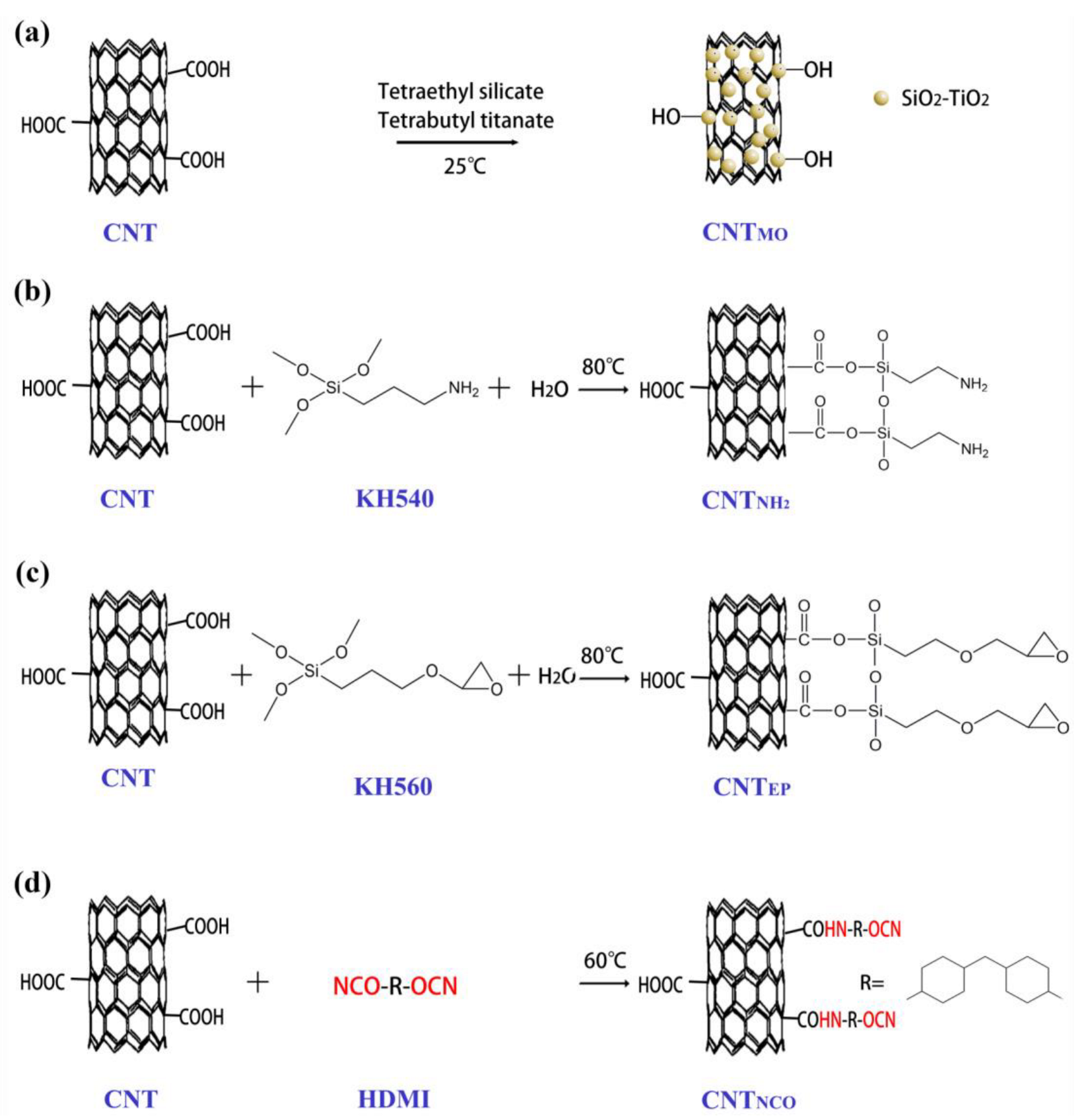
2.3. Modified CNT in SPU Film

Reflux processing was utilized for grafting different functional components on the CNT surface [24]. The modified CNT was mixed with SPU starting materials to prepare composite coatings, as detailed in Figure 2.
(1)
Preparation of CNTMO-SPU
Based on previous works [31,32], CNT (0.4 g) were ultrasonically dispersed in a mixture of deionized H2O (100 mL) and ethanol (EtOH) (20 mL) for 30 min to obtain a homogeneous suspension. Tetraethyl orthosilicate (0.4 g) and tetrabutyl orthotitanate (0.68 g) were dissolved in EtOH (80 mL) and added into the CNT suspension and stirred at room temperature for 8 h, and a thin SiO2–TiO2 nanoparticle covered on the surface of CNT. Then the SiO2–TiO2 nanoparticles modified CNT solids were collected, washed three times with EtOH and dried in vacuum at 80 °C for 12 h to obtain CNTMO.
CNTMO material (0.025 wt% of SPU) was dispersed into the SPU starting materials, and a similar procedure was carried out as pure SPU film preparation (Section 2.2). The final prepared film was named CNTMO-SPU, as shown in Figure 2a.
(2)
Preparation of CNTNH2-SPU
CNT surface was modified by NH2 groups according to the previous literature [14]. Firstly, KH540 (10 mL) was mixed with deionized H2O (90 mL) and hydrolyzed for 30 min. Then, CNT (0.4 g), H2O (20 mL) and EtOH (60 mL) were added to the KH540-solution and sonicated for 30 min. The solution was refluxed at 80 °C for 6 h to graft the NH2 groups on the CNT surface. The NH2 groups modified CNT solids were collected, washed three times with EtOH and dried in vacuum at 80 °C for 12 h to obtain CNTNH2.
CNTNH2 (0.025 wt% of SPU) was added to SPU starting materials, and the final prepared free-standing film was named CNTNH2-SPU, as shown in Figure 2b.
(3)
Preparation of CNTEP-SPU
CNT was modified with epoxy groups using KH560 in the same way as the preparation of CNTNH2. CNTEP (0.025 wt% of SPU) was added to SPU starting materials, and the final prepared free-standing film was named CNTEP-SPU, as shown in Figure 2c.
(4)
Preparation of CNTNCO-SPU
CNT surface was modified by isocyanate (NCO) groups according to the previous literature [31]. CNT (0.4 g) was dispersed into DMF (50 mL), and then HMDI (0.4 g) was added. The mixture was stirred and refluxed at 60 °C for 6 h to grow isocyanate groups on the CNT surface. The NCO groups modified CNT solids were collected, washed three times with EtOH and dried in vacuum at 80 °C for 12 h to obtain CNTNCO.
CNTNCO (0.025 wt% of SPU) was added to SPU starting materials, and the final prepared free-standing film was named CNTNCO-SPU, as shown in Figure 2d.

2.4. Characterization

2.4.1. Structure Characterization

To characterize the functional groups of the CNT, Fourier transforms infrared spectrometer (FTIR, Thermo Fisher Scientific 370, Waltham, MA, USA) was used with a frequency range of 4000–500 cm−1.
The crystallization properties of the samples were analyzed by X-ray diffraction (XRD). The D2-phase, Cu Kα1 line (λ = 1.5406 Å) form Bruker Corporation (Bruker, Billerica, MA, USA) was used, operating at 40 kV/40 mA with 2θ ranging from 10° to 90°.
Scanning electron microscope (SEM) images were obtained by using a Hitachi S–8000 field emission scanning electron microscope (Tokyo, Japan). The cross-section of the sample was scanned at an accelerated voltage of 5 kV, and the sample was quenched in liquid nitrogen before breaking for characterization.

2.4.2. Mechanical Properties of Modified CNT-SPU Films

The mechanical properties of the composite films were investigated according to ISO 37:2005. Five dumbbell samples were tested by CZ–8000 from Zhongzhi Testing Instruments (Shanghai, China), and the tensile rate was 20 mm/min. Each sample was measured at least five times, and the average tensile properties were calculated.

2.4.3. Water and Chemical Resistance Testing of Modified CNT-SPU Films

The water and chemical resistance of the coating were evaluated by the water absorption of the film during storage at room temperature (25 °C) in deionized water, 1 wt% hydrochloric acid and NaOH. The water absorption of the film is determined by measuring its weight immersion for more than 48 h, and the water absorption is calculated according to the following formula:
W = ( m 2 m 1 ) m 1 × 100 %
W—water absorption, wt%; m1—the weight of the dry film, g; m2—weight after water absorption, g.

2.4.4. Anticorrosion Performance

For the anticorrosion test, the CNT-SPU and CNTMO-SPU composites resin were coated on a tinplate by a wet coating preparation device (Huaguo Precision Instrument Co., Ltd., Guangzhou, China), and the coating thickness was 200 μm. The tinplate was polished with sandpaper before use. The coating was tested after curing at room temperature for one week to ensure that the CNT-SPU composite coatings contact well with the polished tinplate substrate, and the obtained samples were named “CNT-SPU coating” and “CNTMO-SPU coating”, respectively.
Potentiodynamic polarization curves and electrochemical impedance (EIS) tests were performed using a CHI600E electrochemical workstation (Chenhua Instruments, Shanghai, China). The test sample was partially immersed in a 3.5 wt% NaCl solution, and a classical three-electrode working system was adopted. The coated steel plate was used as the working electrode (exposed area of 1 cm2), the saturated glycolic electrode (SCE) was used as the reference electrode, and a platinum sheet (area of 1 cm2) was used as the counter electrode. The potentiodynamic polarization curve was scanned at a rate of 0.05 V/s, and the EIS was scanned at a frequency of 10−2 to 105 Hz. The experimental data were fitted with Zsimpwin software (V3.30).

3. Results and Discussion

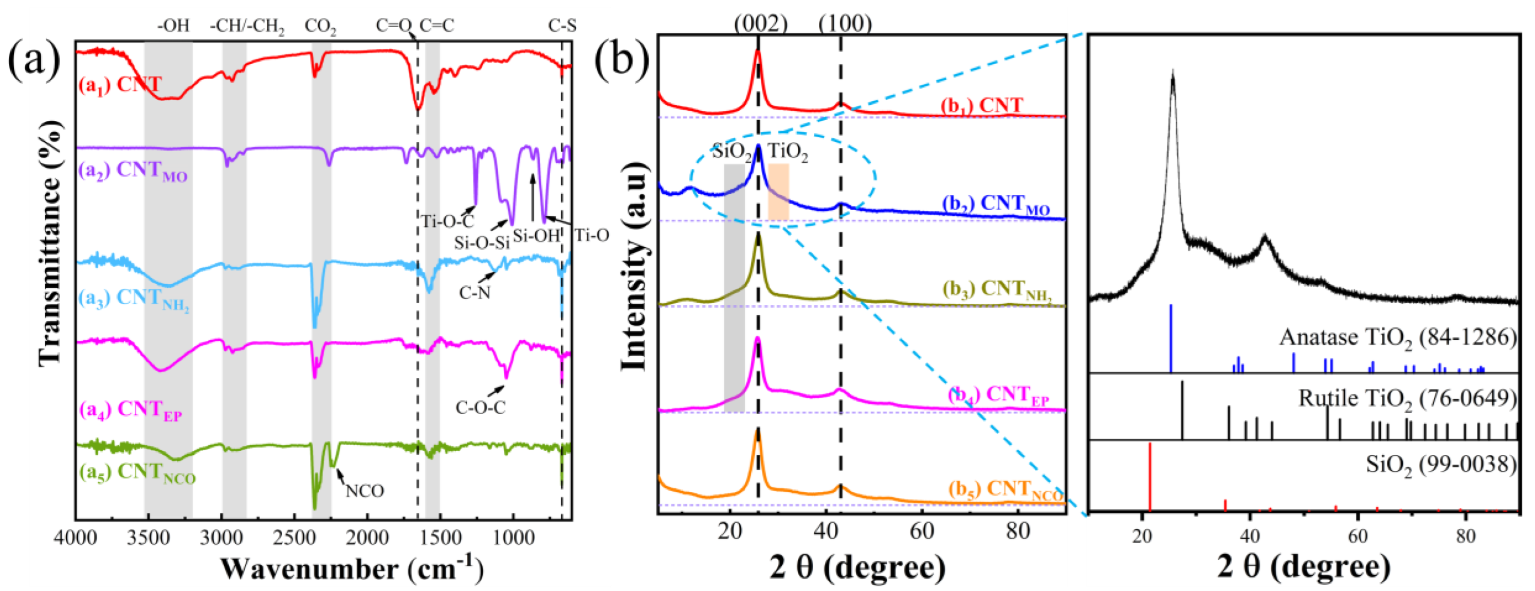
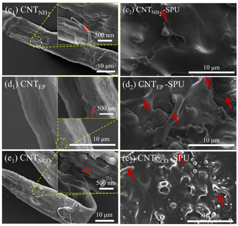
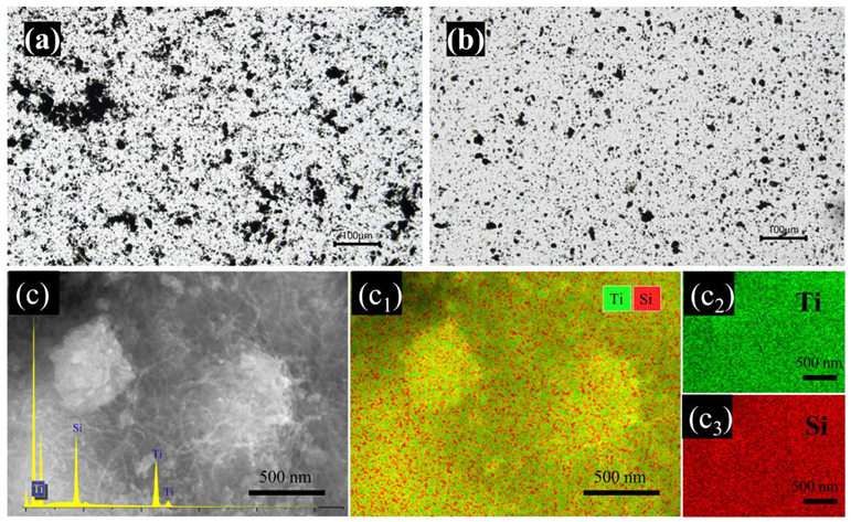
3.1. Structure of Modified CNT

Figure 3 illustrates the FTIR spectra for CNT, CNTMO, CNTNH2, CNTEP and CNTNCO, and the differences in functional groups on the surface of CNT can be observed. The representation of each peak is summarized in Table 1. For pure CNT (Figure 3a1), the broad peak at 3445 cm−1 is caused by -OH liberation on the CNT surface. The peaks in the range of 2800 to 3000 cm−1 are due to CH2/CH3 from the alkyl chain in the precursors, and the peak at 1640 cm−1 is caused by the interaction of the skeletal CNT and carboxyl. Besides, the peak in the range of 600 to 700 cm−1 is caused by C-S groups from CNT [33], which was generated during the CNT preparation by H2SO4 washing. This C-S peak can be observed in all modified CNT samples, indicating C-S bond was not involved in any modification reaction. However, the peak intensity of the C=O group (COOH) at 1640 cm−1 reduced heavily after the surface modification, which may be evidence of the successful modification. In the CNTMO FTIR spectrum (Figure 3a2), additional absorption bands related to Si-O-Si (970–1100 cm−1), Si-OH (870 cm−1), Ti-O-Ti (500–800 cm−1), and Ti-O-C (1210 cm−1) vibrations appeared [32,34,35]. These results indicate that the SiO2 and TiO2 have successfully formed on CNT. When CNTNH2 is concerned (Figure 3a3), the presence of KH540 can be confirmed by the characteristic peaks of -CH2 and -NH2 at 2910 cm−1 and 3400 cm−1 and the peak of C-N at 1120 cm−1. Figure 3a4 shows the FTIR spectrum of CNTEP. The characteristic absorption bands of -C-O-C- appeared at 1050 cm−1, suggesting that part of KH560 silane has been linked to the CNT surface. When CNTNCO is checked, its FTIR spectrum (Figure 3a5) has the characteristic absorption peaks of -NCO at 2250 cm−1, indicating the carboxyl group on the surface of CNT reacted with HMDI, and the -NCO group was successfully grafted onto the surface of CNT.
The structural changes of surface-modified CNT were further evaluated by XRD (Figure 3b). For pure CNT (Figure 3b1), the typical peaks of carbon nanotubes appeared at 2θ = 25.8° and 43.1°, corresponding to (002) and (100) planes, respectively [36]. After various surface modifications (Figure 3b2–b5), the (002) and (100) peaks of CNT can also be observed, indicating that the crystal structure of the CNT did not change due to group modification. Nevertheless, except for CNTNCO (Figure 3b5), an enhanced shoulder appeared on the left of the (002) peak for the CNT samples modified by SiO2–TiO2, KH540 and KH560 (Figure 3b2–b4). This left shoulder of the CNT (002) peak may be caused by amorphous/nanocrystalline SiO2, as the Si component existed in their modification precursors. Besides, an obvious right shoulder can be found near the (002) peak of the CNTMO XRD spectrum (Figure 3b2), which can be considered as amorphous/nanocrystalline titanium dioxide [37,38]. As the diffraction peaks of rutile TiO2 is closer to the right shoulder of the CNT (002) peak, and it maybe exists as rutile TiO2.
According to the preparation procedure and the FTIR&XRD results, Figure 4 shows the surface changes of CNT. In the CNTMO sample (Figure 4a), tetraethyl silicate and tetrabutyl titanate were hydrolyzed and condensed to form SiO2–TiO2 nanoparticles on the CNT surface. For CNTNH2, CNTEP and CNTNCO (Figure 4b–d), KH540, KH560 and HMDI were used for each, and the siloxy group and -NCO group reacted with the COOH of the CNT surface, so the NH2, epoxy and NCO group grafted on the CNT surface, respectively.
The morphologies of CNT before and after modification were studied by SEM (Figure 5a1–e1). The tube wall of pure CNT (Figure 5a1) is smooth and relatively clean. The CNTMO (Figure 5b1) surface is rough, indicating SiO2–TiO2 particles grown on the surface of the tube. According to previous reports, SiO2 and TiO2 prefer to stay together without phase separation [39,40], and the following EDS and elemental mapping (Figure 6c and c1–3) confirmed this. CNTNH2 (Figure 5c1) and CNTEP (Figure 5d1) seem to be covered with a coating on the CNT tube, which may be due to the reaction of the COOH group on the CNT with KH540 and KH560, respectively. The scale-like structure appeared on the surface of CNTNCO (Figure 5e1), which may be related to the reaction of the COOH group on CNT with NCO in HMDI. The cross-sectional morphologies of unmodified and modified CNT-SPU were checked by SEM (Figure 5a2–e2), and no obvious differences can be observed for the CNT-SPU films with different CNT samples, which may be due to the small amount of CNT added. However, the phase separation of CNTNCO-SPU film (Figure 5e2) becomes serious. This may be due to the additional order of NCO compounds leading to poor polymerization of silicone resin and polyurethane. Nevertheless, for CNT and CNTMO, their dispersion states in solution were characterized by a metallographic microscope (Figure 6), and the dispersion of CNTMO (Figure 6b) is much more homogeneous than that of the unmodified CNT sample (Figure 6a), indicating the surface modification of CNT can overcome the agglomeration between the CNTs. The microstructure of the CNTMO was analyzed through SEM technology coupled with EDS and elemental mapping. As shown in Figure 6c, it clearly indicates that Ti and Si elements are homogeneously dispersed on CNTMO, and this strongly suggests the successful loading of SiO2–TiO2 nanoparticles on the CNT.

3.2. Mechanical Properties of SPU Films with Modified CNT

Pure CNT and various modified CNTs were dispersed in SPU, forming different CNT-SPU composites, and their mechanical properties were checked, as shown in Figure 7. The elongation at break and tensile strength can reflect the toughness and strength of the composite films. The tensile strength and elongation at the break of the CNT-SPU film were 2.81 MPa and 146%, respectively. After CNT were modified, the tensile strength values of the CNTMO-SPU and CNTNH2-SPU increased by 0.64 MPa and 0.99 MPa, respectively, compared to the unmodified CNT-SPU composite film, while the tensile strength of the KH560 and NCO modified materials decreased slightly. Only the elongation at the break of the SiO2–TiO2 modified elastomer (CNTMO-SPU) increased, and the elongation at the break of the other three modified composite films decreased. The interfacial strength between inorganic fillers and SPU determines the mechanical properties of the composite elastomer. This change may be because the addition of modified CNT changed the crosslinking degree of SPU. The SiO2–TiO2 encapsulation reduced the surface free energy of CNT, and the surface OH groups formed chemical bonds with SPU, which improved the crosslinking of SPU and enhanced the dispersion of CNT [31]. Although both CNTNH2-SPU and CNTEP-SPU were modified by silane coupling agents, due to a small structure of KH540, CNTNH2 may have small steric hindrance and good compatibility with the NCO group of SPU, resulting in better mechanical properties than the one with KH560. The CNTNCO-SPU film performance became worse, probably because that part of the NCO groups on the surface of the filler reacted with H2O and are not connected to the SPU main chain. In addition, the CNTNCO forms a physical fill in it; thus, its mechanical property is not as good as the film covalent bonding with SPU. Nevertheless, when compared with the values in the literature (Table 2), our samples showed not very good mechanical properties, and the value is only comparable with the one using silicone modified waterborne polyurethane (3.47 MPa, 104.47%) [41]. This may be because the silicone component can reduce the tensile strength, as described in the reference [41]. The smaller elongation break indicated that the crosslinking was high in the CNT-SPU samples, which can well prevent water penetration, as shown in the following section.

3.3. Anticorrosion Performance of SPU Films with Modified CNT

The water absorption of the composite free-standing film before and after modification was checked by immersing the samples in deionized water, 1 wt% HCl and 1 wt% NaOH solution for 48 h. The results are shown in Figure 8d. Compared with the literature values in Table 2, our CNT-SPU component showed very low water absorption. The water absorptions of CNT-SPU (Figure 8a) in H2O, 1% HCl and 1% NaOH solution were 0.390, 0.380 and 0.395 wt%, respectively. Compared to the CNT-SPU with unmodified CNT, the water absorption of the modified CNT in composite SPU films (Figure 8b–e) decreased slightly, suggesting that the modification of CNT improved the water resistance and chemical solvent resistance of the material. Especially the SiO2–TiO2 modified composite film has the lowest water absorption in all three media. Compared with CNT-SPU, it is reduced by 7.6% in the water medium and 6.3% in the chemical medium. This may be due to the addition of CNTMO makes the film more compact, making it difficult for the solvent to penetrate it and not easy to expand when immersed in water. After CNT is modified by KH540 and KH560, the silane coupling agent acts as a “molecular bridge” in the elastomer, which can enhance the adsorption force of the substrate and reduce the degree of freedom of chain segments. This has a certain shielding effect on water molecules, improving the water resistance and chemical resistance of SPU films. The water resistance and chemical resistance of the CNTNCO-SPU films deteriorated because of the serious phase separation of the film, which is also reflected in the SEM (Figure 5e2).
In the water and chemical resistance tests, the CNTMO-SPU film has the best performance, indicating that the film is dense and has good protective properties for the substrate. Therefore, to explore the corrosion resistance of CNTMO filler, the same composite resin (CNTMO-SPU) was coated on polished tinplate and further immersed in 3.5 wt% NaCl solution for 48 h to test their corrosion resistance. The Nyquist plots and Bode plots can also be used to characterize the corrosion resistance of the CNTMO-SPU coating, as shown in Figure 9a,b. The larger the radius in the Nyquist curve is, the larger the polarization resistance, indicating that the coating has a better corrosion resistance [19]. Moreover, in the Bode plot, the high impedance value in the low-frequency region (|Z|f=0.01Hz) means that the coating has good corrosion resistance. The impedance radius of CNTMO-SPU coating is much larger than that of CNT-SPU coating (Figure 9a), indicating the CNTMO-SPU coating has a better anticorrosion ability. The EIS fitting results (summarized in Figure 9c) are based on the equivalent circuit diagram model shown in Figure 9c. The resistance coating (Rc) of CNTMO-SPU coating (3.440 × 10⁶ Ω•cm2) is much larger than that of SPU-CNT (4.155 × 10⁴ Ω•cm2). This means the electrolyte is difficult to penetrate, so the charge transfer number (Rct) of CNTMO-SPU coating (4.036 × 10⁵ Ω•cm2) is also larger than that of CNT-SPU coating (8.149 × 10⁴ Ω•cm2). Besides, in the impedance diagram of CNTMO-SPU coating, there is only one capacitive arc, and there is no Warbury arc, indicating that the composite coating can play a better protective role when the substrate is not corroded. The Bode plots obtained from this test are shown in Figure 9b). In the Bode plot, the impedance moduli of CNT-SPU coating and CNTMO-SPU coating are 4.72 × 10⁴ Ω•cm2 and 3.84 × 10⁶ Ω•cm2, respectively. The larger impedance mode of CNTMO-SPU composite coating indicates that the CNTMO can serve as an excellent barrier in the composite coating.
Figure 10 and Table 3 are the results of potentiodynamic polarization curves. Potentiodynamic polarization curves are often used to characterize the electrochemical corrosion resistance of materials, and the corrosion current density (icorr) and corrosion potential (Ecorr) can be used to compare the corrosion resistance of different materials or coatings [47,48,49,50]. Generally, the lower the icorr is, the better the corrosion resistance. Compared with CNT-SPU coating (icorr: 1.599 × 10⁻⁵ A/cm2), the icorr value of CNTMO-SPU coating reduced to 9.246 × 10⁻⁹ A/cm2. This is also consistent with the results of EIS above. The anticorrosion ability is comparable with those using epoxy resin (as listed in Table 3 for comparison), indicating that they can serve well for metal-substrate protection. This may be because the CNTMO added to the coating is more evenly distributed in the SPU matrix, which could effectively prevent the migration of water molecules, as sketched in Figure 10b,c. Based on the above results and analysis, the anticorrosion effect of the CNTMO-SPU coating is mainly attributed to the CNTMO nanoparticles in SPU coating, and the water resistance test of the coating confirmed that the CNTMO-SPU composite coating has good barrier properties to the electrolyte. In addition, the SiO2–TiO2 on the surface of CNTMO is more likely to form micro-nano structures, which increases the crosslinking degree between CNTMO and SPU. This is beneficial for the CNTMO filler embedding in SPU and can effectively improve the performance of the coating, as reported before [51]. Finally, as a filler, CNTMO can block the pores of the coating and prevent the electrolyte penetration coating from corroding the metal substrate.

4. Conclusions

CNT were functionalized by different approaches, and four modified CNT samples were obtained: CNTMO, CNTNH2, CNTEP and CNTNCO. After figuring out the structures of the modified CNT samples, they were dispersed in homemade SPU resin to prepare composite coatings, and the mechanical and anticorrosion properties of the composite coating were analyzed. In the mechanical tests, the CNTMO-SPU film exhibited the best tensile strength (3.45 MPa) and elongation at break (162%), which were better than the corresponding values of CNT-SPU (2.81 MPa, 146%). Besides, CNTMO-SPU coating also showed the best chemical resistance and anticorrosion ability, with a low water adsorption ratio and low corrosion current density. This may be due to the micro-nano structures of SiO2–TiO2 modified CNT surface. The increase of surface roughness of the CNTMO material can further improve the dispersion of the filler in the SPU resin, resulting in enhancing the mechanical and anticorrosion performance of the coating.

Author Contributions

J.Y.: conceptualization; G.H., X.L., S.W. (Shuchuan Wang) and S.W. (Shirong Wang): Investigation; G.H.: writing—original draft preparation; J.Y. and M.R: writing—review and editing; J.Y. and M.R.: supervision. All authors have read and agreed to the published version of the manuscript.

Funding

This work is financed by the Natural Science Foundation of Shanghai (No. 23ZR1425700).

Institutional Review Board Statement

Not applicable.

Informed Consent Statement

Not applicable.

Data Availability Statement

All data that support the findings of this study are included within the article.

Acknowledgments

Thanks to Runkai Wang (SUES) and Li Wang (North Paint & Coatings Industry Research and Design Institute) for scientific discussion about this work.

Conflicts of Interest

The authors declare no conflict of interest.

References

  1. Ristic, I.S.; Budinski-Simendic, J.; Krakovsky, I.; Valentova, H.; Radicevic, R.; Cakic, S.; Nikolic, N. The properties of polyurethane hybrid materials based on castor oil. Mater. Chem. Phys. 2012, 132, 74–81. [Google Scholar] [CrossRef]
  2. Yilgor, I.; Yilgor, E.; Wilkes, G.L. Critical parameters in designing segmented polyurethanes and their effect on morphology and properties: A comprehensive review. Polymer 2015, 58, A1–A36. [Google Scholar] [CrossRef]
  3. Rostami, A.; Moosavi, M.I. High-performance thermoplastic polyurethane nanocomposites induced by hybrid application of functionalized graphene and carbon nanotubes. J. Appl. Polym. Sci. 2020, 137, 48520. [Google Scholar] [CrossRef]
  4. Valuev, I.L.; Valuev, L.I.; Obydennova, I.V.; Sytov, G.A.; Vanchugova, L.V. Modified polyurethanes as a new type of thromboresistant polymers. Polym. Sci. Ser. A 2010, 52, 824–827. [Google Scholar] [CrossRef]
  5. Cheng, F.; Fan, Y.; He, N.; Song, Y.; Shen, J.; Gong, Z.; Tong, X.; Yang, X. Castor oil based high transparent UV cured silicone modified polyurethane acrylate coatings with outstanding tensile strength and good chemical resistance. Prog. Org. Coat. 2022, 163, 106624. [Google Scholar] [CrossRef]
  6. Galhenage, T.P.; Hoffman, D.; Silbert, S.D.; Stafslien, S.J.; Daniels, J.; Miljkovic, T.; Finlay, J.A.; Franco, S.C.; Clare, A.S.; Nedved, B.T.; et al. Fouling-release performance of silicone oil-modified siloxane-polyurethane coatings. ACS Appl. Mater. Interfaces 2016, 8, 29025–29036. [Google Scholar] [CrossRef] [PubMed] [Green Version]
  7. Yin, C.; Okamoto, R.; Kondo, M.; Tanaka, T.; Hattori, H.; Tanaka, M.; Sato, H.; Iino, S.; Koshiro, Y. Electrospinning of block and graft type silicone modified polyurethane nanofibers. Nanomaterials 2019, 9, 34. [Google Scholar] [CrossRef] [Green Version]
  8. Zadeh, Z.E.; Solouk, A.; Shafieian, M.; Nazarpak, M.H. Electrospun polyurethane/carbon nanotube composites with different amounts of carbon nanotubes and almost the same fiber diameter for biomedical applications. Mater. Sci. Eng. C 2021, 118, 111403. [Google Scholar] [CrossRef]
  9. Alberto, M.; Iliut, M.; Pitchan, M.K.; Behnsen, J.; Vijayaraghavan, A. High-grip and hard-wearing graphene reinforced polyurethane coatings. Compos 2021, 213, 108727. [Google Scholar] [CrossRef]
  10. Charpentier, P.A.; Burgess, K.; Wang, L.; Chowdhury, R.R.; Lotus, A.F.; Moula, G. Nano-TiO2/polyurethane composites for antibacterial and self-cleaning coatings. Nanotechnology 2012, 23, 425606. [Google Scholar] [CrossRef]
  11. Zou, B.; Huang, C.Z.; Wang, J.; Liu, B.Q. Effect of nano-scale TiN on the mechanical properties and microstructure of Si3N4 based ceramic tool materials. Adv. Mach. Manuf. Technol. Viii 2006, 315–316, 154–158. [Google Scholar] [CrossRef]
  12. Guerrero-Martinez, A.; Perez-Juste, J.; Liz-Marzan, L.M. Recent progress on silica coating of nanoparticles and related nanomaterials. Adv. Mater. 2010, 22, 1182–1195. [Google Scholar] [CrossRef]
  13. Gonzalez-Carrero, S.; Galian, R.E.; Perez-Prieto, J. Organometal halide perovskites: Bulk low-dimension materials and nanoparticles. Part. Part. Syst. Char. 2015, 32, 709–720. [Google Scholar] [CrossRef]
  14. He, Y.; Chen, C.; Zhong, F.; Chen, H.; Qing, D. Synthesis and properties of iron oxide coated carbon nanotubes hybrid materials and their use in epoxy coatings. Polym. Adv. Technol. 2015, 26, 414–421. [Google Scholar] [CrossRef]
  15. Bai, Y.; Park, I.S.; Lee, S.J.; Bae, T.S.; Watari, F.; Uo, M.; Lee, M.H. Aqueous dispersion of surfactant-modified multiwalled carbon nanotubes and their application as an antibacterial agent. Carbon 2011, 49, 3663–3671. [Google Scholar] [CrossRef]
  16. Bhattacharyya, A.; Joshi, M. Functional properties of microwave-absorbent nanocomposite coatings based on thermoplastic polyurethane-based and hybrid carbon-based nanofillers. Polym. Adv. Technol. 2012, 23, 975–983. [Google Scholar] [CrossRef]
  17. Wang, J.L.; Meng, L.J. Influence of carbon nano-fiber on mechanical property of PALC. Energy Eng. Environ. Eng. 2014, 535, 785–787. [Google Scholar] [CrossRef]
  18. Wu, Q.; Miao, W.-S.; Zhang, Y.-D.; Gao, H.-J.; Hui, D. Mechanical properties of nanomaterials: A review. Nanotechnology 2020, 9, 259–273. [Google Scholar] [CrossRef]
  19. Wang, F.; Feng, L.; Lu, M. Mechanical properties of multi-walled carbon nanotube/waterborne polyurethane conductive coatings prepared by electrostatic spraying. Polymers 2019, 11, 714. [Google Scholar] [CrossRef] [Green Version]
  20. Zhang, C.; Vennerberg, D.; Kessler, M.R. In situ synthesis of biopolyurethane nanocomposites reinforced with modified multiwalled carbon nanotubes. J. Appl. Polym. Sci. 2015, 132, 42515. [Google Scholar] [CrossRef]
  21. Sainsbury, T.; Fitzmaurice, D. Templated assembly of semiconductor and insulator nanoparticles at the surface of covalently modified multiwalled carbon nanotubes. Chem. Mat. 2004, 16, 3780–3790. [Google Scholar] [CrossRef]
  22. Xiao, Y.-K.; Ji, W.-F.; Chang, K.-S.; Hsu, K.-T.; Yeh, J.-M.; Liu, W.-R. Sandwich-structured rGO/PVDF/PU multilayer coatings for anti-corrosion application. RSC Adv. 2017, 7, 33829–33836. [Google Scholar] [CrossRef] [Green Version]
  23. He, Y.; Ming, Y.; Li, W.; Li, Y.F.; Wu, M.Q.; Song, J.Z.; Li, X.J.; Liu, H. Highly stable and flexible pressure sensors with modified multi-walled carbon nanotube/polymer composites for human monitoring. Sensors 2018, 18, 1338. [Google Scholar] [CrossRef] [PubMed] [Green Version]
  24. Zeng, W.; Liu, F.; He, J. Physicochemical properties of Bis-GMA/TEGDMA dental resin reinforced with silanized multi-walled carbon nanotubes. Silicon 2019, 11, 1345–1353. [Google Scholar] [CrossRef]
  25. Rastogi, R.; Kaushal, R.; Tripathi, S.K.; Sharma, A.L.; Kaur, I.; Bharadwaj, L.M. Comparative study of carbon nanotube dispersion using surfactants. J. Colloid. Interf. Sci. 2008, 328, 421–428. [Google Scholar] [CrossRef] [PubMed]
  26. Aguiar, V.O.; Pita, V.J.R.R.; Marques, M.D.F.V. Nanocomposites of ultrahigh molar mass polyethylene and modified carbon nanotubes. J. Appl. Polym. Sci. 2019, 136, 47459. [Google Scholar] [CrossRef]
  27. Meng, H.; Yan, T.; Yu, J.; Jiao, F. Super-hydrophobic and super-lipophilic functionalized graphene oxide/polyurethane sponge applied for oil/water separation. Chin. J. Chem. Eng. 2018, 26, 957–963. [Google Scholar] [CrossRef]
  28. Haghdadeh, P.; Ghaffari, M.; Ramezanzadeh, B.; Bahlakeh, G.; Saeb, M.R. Polyurethane coatings reinforced with 3-(triethoxysilyl)propyl isocyanate functionalized graphene oxide nanosheets: Mechanical and anti-corrosion properties. Prog. Org. Coat. 2019, 136, 105243. [Google Scholar] [CrossRef]
  29. Li, S.; Du, X.; Hou, C.; Hao, X.; Jia, J.; Guan, T.; Yi, T.; Ma, G. One-pot two-step perfluoroalkylsilane functionalization of multi-walled carbon nanotubes for polyurethane-based composites. Compos. Sci. Technol. 2017, 143, 46–55. [Google Scholar] [CrossRef]
  30. Taraghi, I.; Paszkiewicz, S.; Fereidoon, A.; Szymczyk, A.; Stanik, R.; Gude, M.; Linares, A.; Ezquerra, T.A.; Piesowicz, E.; Wilpiszewska, K.; et al. Thermally and electrically conducting polycarbonate/elastomer blends combined with multiwalled carbon nanotubes. J. Thermoplast. Compos. 2021, 34, 1488–1503. [Google Scholar] [CrossRef]
  31. Navidfar, A.; Sancak, A.; Yildirim, K.B.; Trabzon, L. A study on polyurethane hybrid nanocomposite foams reinforced with multiwalled carbon nanotubes and silica nanoparticles. Polym. Plast. Technol. Eng. 2018, 57, 1463–1473. [Google Scholar] [CrossRef]
  32. Wang, A.; Wang, Y.; Yu, W.; Huang, Z.; Fang, Y.; Long, L.; Song, Y.; Cifuentes, M.P.; Humphrey, M.G.; Zhang, L.; et al. TiO2-multi-walled carbon nanotube nanocomposites: Hydrothermal synthesis and temporally-dependent optical properties. RSC Adv. 2016, 6, 20120–20127. [Google Scholar] [CrossRef] [Green Version]
  33. Ţucureanu, V.; Matei, A.; Avram, A.M. FTIR spectroscopy for carbon family study. Crit. Rev. Anal. Chem. 2016, 46, 502–520. [Google Scholar] [CrossRef] [PubMed]
  34. Li, X.; Yang, J.; Wang, J.; Chang, X.; Xu, J.; Wu, Z. A stable super-amphiphilic surface created from superhydrophobic silica/epoxy coating by low-temperature plasma-treatment. Surf. Eng. 2021, 37, 1282–1289. [Google Scholar] [CrossRef]
  35. Yang, J.; Zhang, J.; Zou, B.; Zhang, H.; Wang, J.; Schubert, U.; Rui, Y. Black SnO2–TiO2 nanocomposites with high dispersion for photocatalytic and photovoltalic applications. ACS Appl. Nano Mater. 2020, 3, 4265–4273. [Google Scholar] [CrossRef]
  36. Zhang, D.; Shi, L.; Fang, J.; Li, X.; Dai, K. Preparation and modification of carbon nanotubes. Mater. Lett 2005, 59, 4044–4047. [Google Scholar] [CrossRef]
  37. Deng, H.; Zhang, H. In situ synthesis and hydrothermal crystallization of nanoanatase TiO2–SiO2 coating on aramid fabric (HTiSiAF) for UV protection. Microsc. Res. Tech. 2015, 78, 918–925. [Google Scholar] [CrossRef]
  38. Ren, C.; Qiu, W.; Zhang, H.; He, Z.; Chen, Y. Degradation of benzene on TiO2/SiO2/Bi2O3 photocatalysts under UV and visible light. J. Mol. Catal. A Chem. 2015, 398, 215–222. [Google Scholar] [CrossRef]
  39. Zhang, M.; Lin, Z.; Huang, Q.; Zhu, Y.; Hu, H.; Chen, X. Green synthesis of submicron-sized Ti-rich MWW zeolite powders via a novel mechanochemical dry gel conversion in mixed steam environment. Adv. Powder Technol. 2020, 31, 2025–2034. [Google Scholar] [CrossRef]
  40. Wang, G.; Wen, S.; Qian, S.; Wang, J.; Wang, C.; Chen, Y. Synthesis of novel nano hyperbranched polymer resin and its corrosion resistance in coatings. Prog. Org. Coat. 2020, 140, 105496. [Google Scholar] [CrossRef]
  41. Qian, Y.; Dong, F.; Guo, L.; Xu, X.; Liu, H. Terpene derivative-containing silicone two-component waterborne polyurethane for coatings. Prog. Org. Coat. 2021, 153, 106137. [Google Scholar] [CrossRef]
  42. Tijing, L.D.; Park, C.-H.; Kang, S.-J.; Amarjargal, A.; Kim, T.-H.; Pant, H.R.; Kim, H.J.; Lee, D.H.; Kim, C.S. Improved mechanical properties of solution-cast silicone film reinforced with electrospun polyurethane nanofiber containing carbon nanotubes. Appl. Surf. Sci 2013, 264, 453–458. [Google Scholar] [CrossRef]
  43. Kurańska, M.; Aleksander, P.; Mikelis, K.; Ugis, C. Porous polyurethane composites based on bio-components. Compos. Sci. Technol. 2013, 75, 70–76. [Google Scholar] [CrossRef]
  44. Zhang, X.J.; Cai, Y.Q.; Zhang, X.W.; Aziz, T.; Fan, H.; Bittencourt, C. Synthesis and characterization of eugenol-based silicone modified waterborne polyurethane with excellent properties. J. Appl. Polym. Sci. 2021, 138, 47562. [Google Scholar] [CrossRef]
  45. Xu, S.; Xie, L.; Yu, X.; Xiong, Y.; Tang, H. Synthesis and characterization of phenyl polysiloxane modified polyurea/polyurethanes. J. Polym. Sci. Part A Polym. Chem. 2015, 53, 1794–1805. [Google Scholar] [CrossRef]
  46. Cataldi, P.; Profaizer, M.; Bayer, I.S. Preventing water-induced mechanical deterioration of cardboard by a sequential polymer treatment. Ind. Eng. Chem. Res. 2019, 58, 6456–6465. [Google Scholar] [CrossRef]
  47. Guo, L.; Jing, L.Z.; Liu, Y.; Zou, B.J.; Hua, S.C.; Zhang, J.P.; Yu, D.Y.; Wang, S.C.; Wang, S.R.; Wang, L.D.; et al. Enhanced Dispersion of Graphene in Epoxy-Acrylic Waterborne Anticorrosion Coating: Bifunctional Ligands Linking Graphene to SiO2. Int. J. Electrochem. Sci. 2018, 13, 11867–11881. [Google Scholar] [CrossRef]
  48. Zou, B.; Chang, X.; Yang, J.; Wang, S.; Xu, J.; Wang, S.; Samukawa, S.; Wang, L. Plasma treated h-BN nanoflakes as barriers to enhance anticorrosion of acrylic coating on steel. Prog. Org. Coat. 2019, 133, 139–144. [Google Scholar] [CrossRef]
  49. Li, H.; Wang, J.; Yang, J.; Zhang, J.; Ding, H. Large CeO2 nanoflakes modified by graphene as barriers in waterborne acrylic coatings and the improved anticorrosion performance. Prog. Org. Coat. 2020, 143, 105607. [Google Scholar] [CrossRef]
  50. Shen, Y.F.; Yang, J.X.; Wang, S.C.; Jing, L.Z.; Zheng, H.; Du, Y.Y.; Zou, B.J.; Lei, X.Z.; Xu, J.L. Size Influences of SiO2-graphene Barrier on the Corrosion Resistance of Epoxy-Acrylic Waterborne Coating. Int. J. Electrochem. Sci. 2021, 16, 151018. [Google Scholar] [CrossRef]
  51. Hsu, Y.W.; Wu, C.C.; Wu, S.M.; Su, C.C. Synthesis and Properties of Carbon Nanotube-Grafted Silica Nanoarchitecture-Reinforced Poly (Lactic Acid). Materials 2017, 10, 829. [Google Scholar] [CrossRef] [PubMed] [Green Version]
  52. Liao, Z.; Zhang, T.; Qiao, S.; Zhang, L. Preparation and Electrochemical Properties of Graphene/Epoxy Resin Composite Coating. IOP Conf. Ser. Earth Environ. Sci. 2017, 94, 012072. [Google Scholar] [CrossRef]
  53. Xu, H.Y.; Li, B.; Han, X.; Wang, Y.; Zhang, X.R.; Komarneni, S. Synergic enhancement of the anticorrosion properties of an epoxy coating by compositing with both graphene and halloysite nanotubes. J. Appl. Polym. Sci. 2019, 136, 47562. [Google Scholar] [CrossRef]
  54. Damej, M.; Hsissou, R.; Berisha, A.; Azgaou, K.; Sadiku, M.; Benmessaoud, M.; Labjar, N.; El hajjaji, S. New epoxy resin as a corrosion inhibitor for the protection of carbon steel C38 in 1M HCl. experimental and theoretical studies (DFT, MC, and MD). J. Mol. Struct. 2022, 1254, 132425. [Google Scholar] [CrossRef]
  55. Ji, R.; Ma, M.; He, Y.; Liu, C.; Fang, T.; Zhang, Z.; Wang, Y.; He, Y.; Wu, J. Improved corrosion resistance of Al2O3 ceramic coatings on AZ31 magnesium alloy fabricated through cathode plasma electrolytic deposition combined with surface pore-sealing treatment. Ceram. Int. 2018, 44, 15192–15199. [Google Scholar] [CrossRef]
Figure 1. Synthesis of SPU, (a) 1,2-epoxybutane; (b) amino silicone oil; (c) HMDI; (d) SPU.
Coatings 13 00634 g001
Figure 2. Experimental scheme of modified CNT in SPU. (a) preparation of CNTMO-SPU; (b) preparation of CNTNH2-SPU; (c) preparation of CNTEP-SPU; (d) preparation of CNTNCO-SPU.
Coatings 13 00634 g002
Figure 3. (a) FTIR spectra(a) and XRD results (b) of pristine and four modified CNT inorganic filler.
Coatings 13 00634 g003
Figure 4. Scheme of surface changes of modified CNT. (a) CNTMO; (b) CNTNH2; (c) CNTEP; (d) CNTNCO.
Coatings 13 00634 g004
Figure 5. SEM pictures of modified CNT samples ((a1e1) Multiple: 2 k, Multiple for insert: 50 k) and the cross-section of various CNT-SPU composite films ((a2e2) Multiple: 5 k): (a1) CNT, (b1) CNTMO, (c1) CNTNH2, (d1) CNTEP, (e1) CNTNCO, (a2) CNT-SPU, (b2) CNTMO-SPU, (c2) CNTNH2-SPU, (d2) CNTEP-SPU, (e2) CNTNCO-SPU.
Coatings 13 00634 g005aCoatings 13 00634 g005b
Figure 6. Metallographic microscopic photographs of unmodified CNT (a) and CNTMO (b) in SPU resin; EDS (c) and elemental mapping of CNTMO (c1c3).
Coatings 13 00634 g006
Figure 7. Mechanical properties of CNT-SPU composite free-standing film before and after modification: (a) CNT-SPU, (b) CNTMO-SPU, (c) CNTNH2-SPU, (d) CNTEP-SPU, (e) CNTNCO-SPU. The insert in the upper right corner is the photo of CNTMO-SPU free-standing film.
Coatings 13 00634 g007
Figure 8. Water resistance of composite free-standing film before and after modification: (a) CNT-SPU, (b) CNTMO-SPU, (c) CNTNH2-SPU, (d) CNTEP-SPU, (e) CNTNCO-SPU.
Coatings 13 00634 g008
Figure 9. Nyquist (a) and Bode plots (b) of the synthesized CNT-SPU and CNTMO-SPU coatings after 48 h immersion in 3.5 wt% NaCl solution. The insert in (a) upper left corner is the photo of CNTMO-SPU coating. The equivalent circuit diagram model of coatings is shown in (c), and the main parameters of EIS fitting for CNT-SPU and CNTMO-SPU coatings are also listed in (c).
Coatings 13 00634 g009
Figure 10. Potentiodynamic polarization curves (a), anticorrosion schematics (b,c) of CNT-SPU coating and CNTMO-SPU coating.
Coatings 13 00634 g010
Table 1. The representation of each peak.
Wavenumber (cm−1)Functional GroupCharacteristic Vibration Mode for
3600–3200-OHsurface carboxylic, -OH from absorbed H2O in the air
3400-NH2N-CNT, NH or NH2
3000–2800CH2/CH3from alkyl chain
2350CO2CO2 from the air
2250-NCOisocyanate (-N=C=O)
1640C=Othe skeletal CNT and carboxyl or ketone groups
1580–1530C=Chexagonal structure on the pristine CNTs
1210Ti-O-Cfrom tetrabutyl titanate
970–1100Si-O-SiSiO2 and silanes
870Si-OHsilanes
1120C-Nfrom KH540
500–800Ti-O-TiTiO2
663C-SCNT
Table 2. Summary of mechanical properties and water absorption of SPU.
SampleTensile Strength (MPa)Elongation Break (%)Water Absorption
(%)
Reference
CNTMO-SPU3.451620.360 ± 0.053This work
WPU-Si3.47 ± 0.52104.47 ± 9.2112.58 ± 0.81Qian, Y. et al. [41]
0.1 wt% CNT/PU–silicone composite12.7 ± 2710 ± 40/Tijing, L. D. et al. [42]
P1-60//0.90Kurańska, M. et al. [43]
WPU-322.4 ± 0.5781.1 ± 137.6Zhang, X. J. et al. [44]
SPU-47.0366.50.50Xu, S. et al. [45]
MD72.5 ± 3.53.6 ± 0.3/Cataldi, P. et al. [46]
Table 3. Results of potentiodynamic polarization test for different coatings.
SampleEcorr
(V)
icorr
(A/cm2)
ba
(mV/decade)
−bc
(mV/decade)
μ
(g∙m−2∙h−1)
CNT-SPU coating–0.2971.599 × 10−53.8772.6811.66 × 10−1
CNTMO-SPU coating–0.6729.246 × 10−95.0464.8829.62 × 10−5
5% coating [52]–0.0831.78 × 10−8
H05G08EP [53]–0.775.6 × 10−7
1 mM TTA [54]–0.4277.28 × 10−758.6–77.8
CPED/epoxy resin-treated [55]–1.276.0 × 10−5
EA+500nmSiO2+P+Gr [50]–0.5327.1 × 10−96311117.24 × 10−5
Disclaimer/Publisher’s Note: The statements, opinions and data contained in all publications are solely those of the individual author(s) and contributor(s) and not of MDPI and/or the editor(s). MDPI and/or the editor(s) disclaim responsibility for any injury to people or property resulting from any ideas, methods, instructions or products referred to in the content.

