Article

Microstructure, Mechanical Properties, Wear and Erosion Performance of a Novel High Entropy Nitride (AlCrTiMoV)N Coating Produced by Cathodic Arc Evaporation

1
Department of Mechanical and Aerospace Engineering, Carleton University, 1125 Colonel by Dr, Ottawa, ON K1S 5B7, Canada
2
National Research Council of Canada, 1200 Montreal Rd, Ottawa, ON K1A 0R6, Canada
*
Authors to whom correspondence should be addressed.
Coatings 2023, 13(3), 619; https://doi.org/10.3390/coatings13030619
Submission received: 13 February 2023 / Revised: 8 March 2023 / Accepted: 11 March 2023 / Published: 14 March 2023
(This article belongs to the Special Issue Chemical/Physical Vapor Deposition Coatings on Metallic Substrates)

Abstract

:
(AlCrTiMoV)N high entropy nitride film was prepared on 17-4PH stainless steel substrate using cathodic arc evaporation (CAE). The composition, microstructure, and thermal stability were investigated using scanning electron microscopy (SEM), transmission electron microscopy (TEM), and X-ray diffraction (XRD). Mechanical properties such as hardness and Young’s modulus and coating performance against wear and erosion were also evaluated. The results show that the (AlCrTiMoV)N coating assumes a single-phased solid solution B1 FCC structure. It has excellent thermal stability and retains its structure with no decomposition observed up to a temperature of 1000 °C. The hardness and elastic modulus are measured as 21.3 GPa and 304 GPa, respectively. The coating contains some metallic droplets. As a potential protective coating, the (AlCrTiMoV)N coating has a lower wear rate but a higher erosion rate when compared to the TiN baseline coating.

1. Introduction

Nitride coatings deposited by physical vapor deposition (PVD) techniques, such as TiN, CrN, and AlTiN, have been extensively used as protective coatings [1,2]. Of these, TiN has been the most used in industrial application for its hard and wear resistance properties [3]. Recent developments in novel coatings have expanded upon these binary and ternary nitrides and illustrated the benefits of using high entropy alloys (HEA) to further improve coating performance. High entropy alloys are typically composed of five or more primary elements, each compositing 5–35 at% [4]. HEAs have been found to have high strength/hardness, good thermal stability and high wear, corrosion and oxidation resistance [4,5]. The field of study has quickly expanded from HEA alloys to high entropy nitride (HEN) coatings to further improve hardness, wear and corrosion resistance [6].
Existing literature has investigated various compositions of HEN coatings. Common studies involve the effect of chamber pressure, nitrogen ratio or substrate temperature on coating microstructure and mechanical properties. Studies on coatings such as (CrNbTiAlV)N [7] (AlCrTaTiZr)N [8], (AlCrTiZrHf)N [9], (HfNbTiVZr)N [10] and (AlCrMoSiTi)N [11] have reported on coatings with a single phase B1 FCC structure with a preferred (111) orientation and high hardness, in the range of 30–40 GPa which is attributed to solid solution strengthening and a dense film structure. These studies have also reported high wear resistance [9], scratch resistance [10] and thermal phase stability [11]. While a significant majority of HEN coatings are produced by magnetron sputtering [8,9,10,11,12,13], a limited number of studies have investigated the use of cathodic arc evaporation to deposit HEN coatings, including those on (TiZrNbAlYCr)N [14], (TiZrHfVNbTa)N [15], (TiZrAlYNb)N [16] and (MoNbTaVW)N [17]. Compared to magnetron sputtering which has a lower ion flux and ion energy, in CAE the high current density of the arc discharge produces a plasma with high ion flux and ion energy, which improves the coatings’ structure and properties [18]. Considering the promising properties of HEN coatings and the increasing use of CAE, this study was initiated with the objective to develop a CAE HEN coating and to evaluate the resulting microstructure and performance of the coating.
Coatings have been extensively used to protect components in adverse conditions requiring wear and erosion resistance [19]. Wear is material removal due to contact with another body [20]. Many forms of wear exist, including frictional wear (surface against surface) where material is removed by abrasive wear due to objects sliding against another body or adhesive wear due to bonding between objects in contact [20,21]. Erosion is a form of wear by impacting particles onto a hard surface in which material is removed by plowing/micro cutting or by fracture [20]. Extensive research has been undertaken to quantify the wear and erosion resistance of various coating systems [3,19,21] and it is essential to design suitable coatings to protect objects from these forms of degradation. However, limited work has investigated the use of HENs for the application of protective coatings [7,9]. In particular, a target material of AlCrTiMoV was designed and used to deposit the (AlCrTiMoV)N coating using the CAE method in a reactive nitrogen environment. Al and Ti were, in fact, firstly chosen as the major elements because AlTiN coating has demonstrated outstanding mechanical properties and tribological performance and has been widely used for cutting tools [22,23,24]. Cr, V and Mo elements were also incorporated into the coating, with the goal to improve the thermal stability [25], oxidation/corrosion resistance and solid lubricity of the coating [26,27]. This composition continues to build upon existing (AlCrTiV)N, which was reported to have excellent mechanical properties [28]. The goal of this study is to explore novel high entropy nitride coatings to achieve superior performance for application in adverse environments and to investigate the use of the cathodic arc evaporation technique as a method of producing HEN coatings. The target of this paper is to characterize the (AlCrTiMoV) N coatings produced by CAE and identify their performance as a protective coating for applications requiring wear and erosion resistance. The microstructure, thermal stability and mechanical properties of the coating were first characterized, which were followed by dry sliding wear testing and solid particle erosion testing, both of which are pertinent to intended industrial applications.

2. Materials and Methods

The (AlCrTiMoV)N HEN coating was deposited onto 17-4 PH stainless steel flat circular coupons sized 50 mm in diameter and 3 mm in thickness. Prior to deposition, coupons were ultrasonically cleaned in alcohol and placed on a two-axis-of-rotation turntable. Deposition was performed using a Metaplas Ionon MZR-304 cathodic arc coater (Sulzer MetaplasBergisch, Gladbach, Germany). Two cathodes, composed of Al 30%, Cr 20%, Ti 20%, Mo 15%, and V 15% by atomic percentage were mounted vertically 180 degrees apart in the deposition chamber. Precleaning was performed by arc enhanced glow discharge within the coater with a bias voltage of −280 V. Deposition was performed for a total 300 ampere hour (Ah) in a reactive nitrogen environment, using the following process parameters which were optimized from the preliminary study. The gas inflow was controlled to maintain a fixed argon flow rate of 150 sccm and the nitrogen was regulated to maintain a constant pressure of 5 Pa (5 × 10⁻² mbar). A current of 85 A was applied onto each cathode and a bias voltage of −20 V was applied to the turntable to provide ion bombardment to the growing coating and lower the coating residual stress. The chamber temperature was maintained at 400 °C throughout the coating process. Additional samples were produced under the same conditions onto silicon wafers but for 70 Ah for transmission electron microscope (TEM) analysis. Baseline TiN coating samples were also produced using the same deposition facility except at a bias voltage of −100 V and a chamber pressure of 0.8 Pa (8 × 10⁻³ mbar).
Imaging of the coating surface and cross-section was performed using a Philips XL30 field emission scanning electron microscope (SEM, Philips, Amsterdam, The Netherlands) equipped with an energy dispersive X-ray spectrometer (EDS). EDS mapping was performed using a Tescan Vega-II XMU SEM (Tescan, Brno, Czech Republic) with an Oxford Inca Energy X-Act EDS. The phase composition was analyzed by X-ray diffraction (XRD) using a Bruker AXS D8 Discover diffractometer (Bruker, Billerica, MA, United States) with the Bragg–Brentano configuration and Cu Kα radiation (λ = 1.5406 Å) at 40 kV and 40 mA and with a 2θ angle range of 30–85°. High temperature XRD was performed using a Bruker AXS D8 Discover diffractometer equipped with an Anton Paar HTK 1200 N (Anton Paar, Graz, Austria) high temperature oven. The measurements were carried out with a 2θ angle range of 33° to 69° at room temperature (RT), 600 °C, 700 °C, 800 °C, 900 °C and 1000 °C in sequence. The sample was heated in the argon filled chamber at a heating rate of 15 °C per minute and held at the measurement temperature for 20 min prior to each scan. Cross-sectional TEM samples were prepared by standard dimpling and ion milling procedures and examined in a JEOL JEM 2100F (JEOL, Tokyo, Japan) operating at 200 kV.
The Vickers hardness and Young’s modulus were measured on the coating cross-section using a CSEM nano hardness tester (CSM Instruments, Neuchâtel, Switzerland) with a Berkovich indenter and averaged over seven measurements. The maximum applied load of 50 mN was applied and held for 15 s. Samples used for erosion and wear testing were tumbled for 30 min with a SiO2 medium to reduce coating surface roughness. Wear properties were evaluated by pin on disc sliding wear tests, using a WC-6%Co ball 5 mm diameter counter body with a 8 mm wear track, applied normal load of 10 N, sliding speed of 20 cm/s and sliding distance of 1 km. The frictional force was recorded throughout the test. The depth profile of the wear track was measured along the radial directions of the wear track using a Bruker DektakXT surface profilometer (Bruker, Billerica, MA, United States) at six locations, from which the average wear track area (A) can be calculated and used to calculate the wear volume. The specific wear rate of the coating was obtained by normalizing its wear volume with the total sliding distance and the applied normal load. The wear volume of the WC-6%Co ball is calculated according to Equation (1), from which the specific wear rate of the ball can be calculated [29].
Wear   Volume = 2 3 π R 3 1 1 d 2 R 2 1 3 π d 2 2 R 2 d 2 2
where R is the ball radius and d is the diameter of the wear scar on the ball.
Erosion data were obtained according to ASTM standard G76-04 [30], at room temperature using an S. S. White Abrasive Jet unit (model HME) placed on a Sartorius balance (±0.5 g). The erodent used for the tests was sharp edged AccuBRADE-50 Blend #3 alumina (Al2O3) with an average particle size of 50 μm, as shown in Figure 1. The erosion tests were conducted at an average particle speed of 84 m/s, at a particle feed rate approximately 1 g/min and under impingent angles of 30° and 90° in 15° increments. During testing, the coupon surface to nozzle tip distance was maintained constant at 38 ± 1 mm. The sample weight loss due to erosion was measured using a precision balance with an accuracy of 10−5 g. The erosion rate is calculated from the slope of the line of best fit for the sample weight loss vs erosion medium used for each angle. Sample weight and erodent usage measurements were recorded at three or more points throughout the test. The erosion test was terminated immediately after the coating was perforated.

3. Results and Discussion

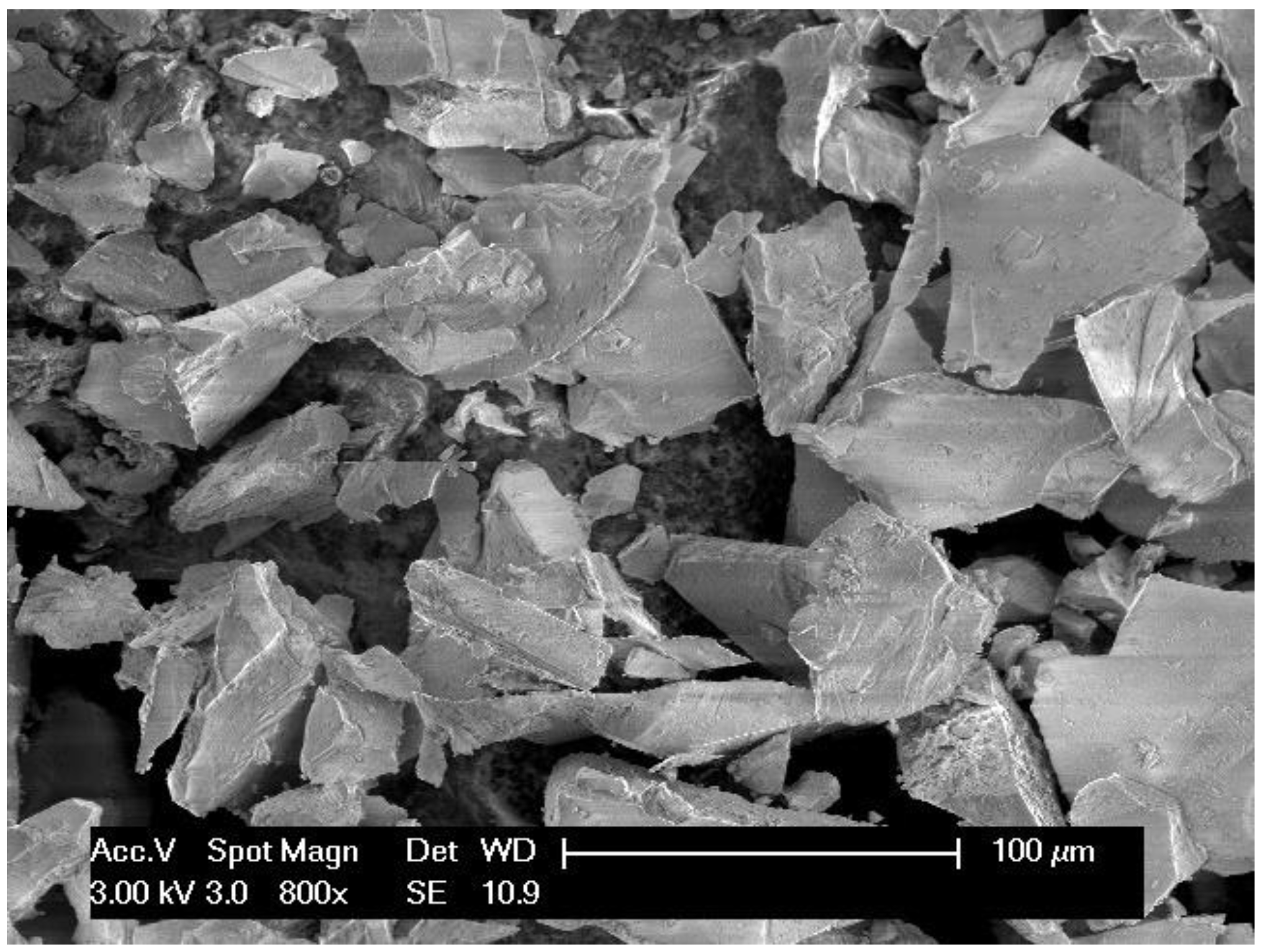
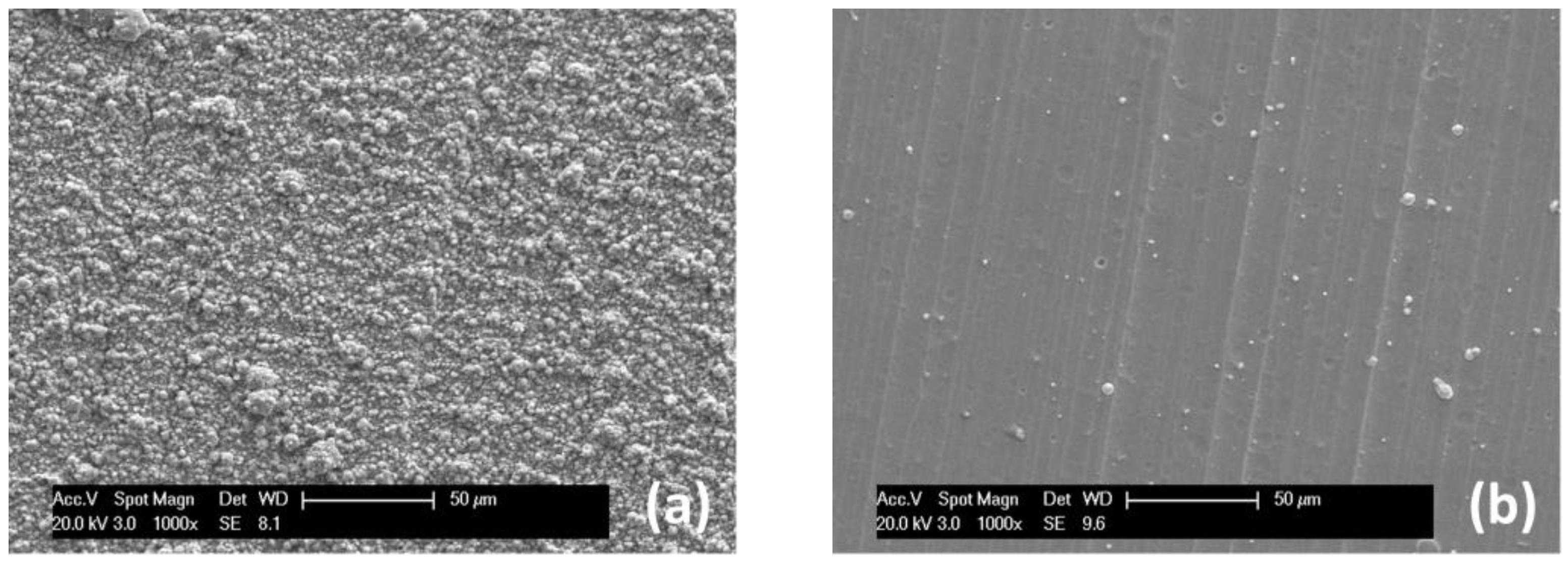
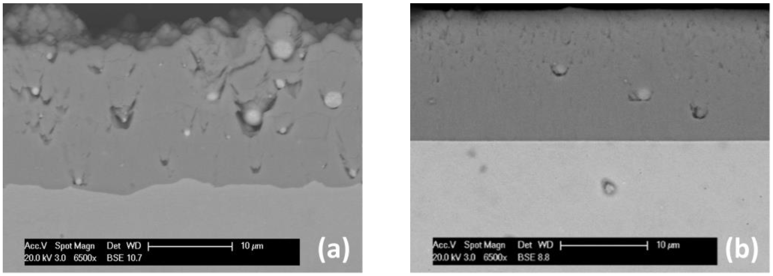
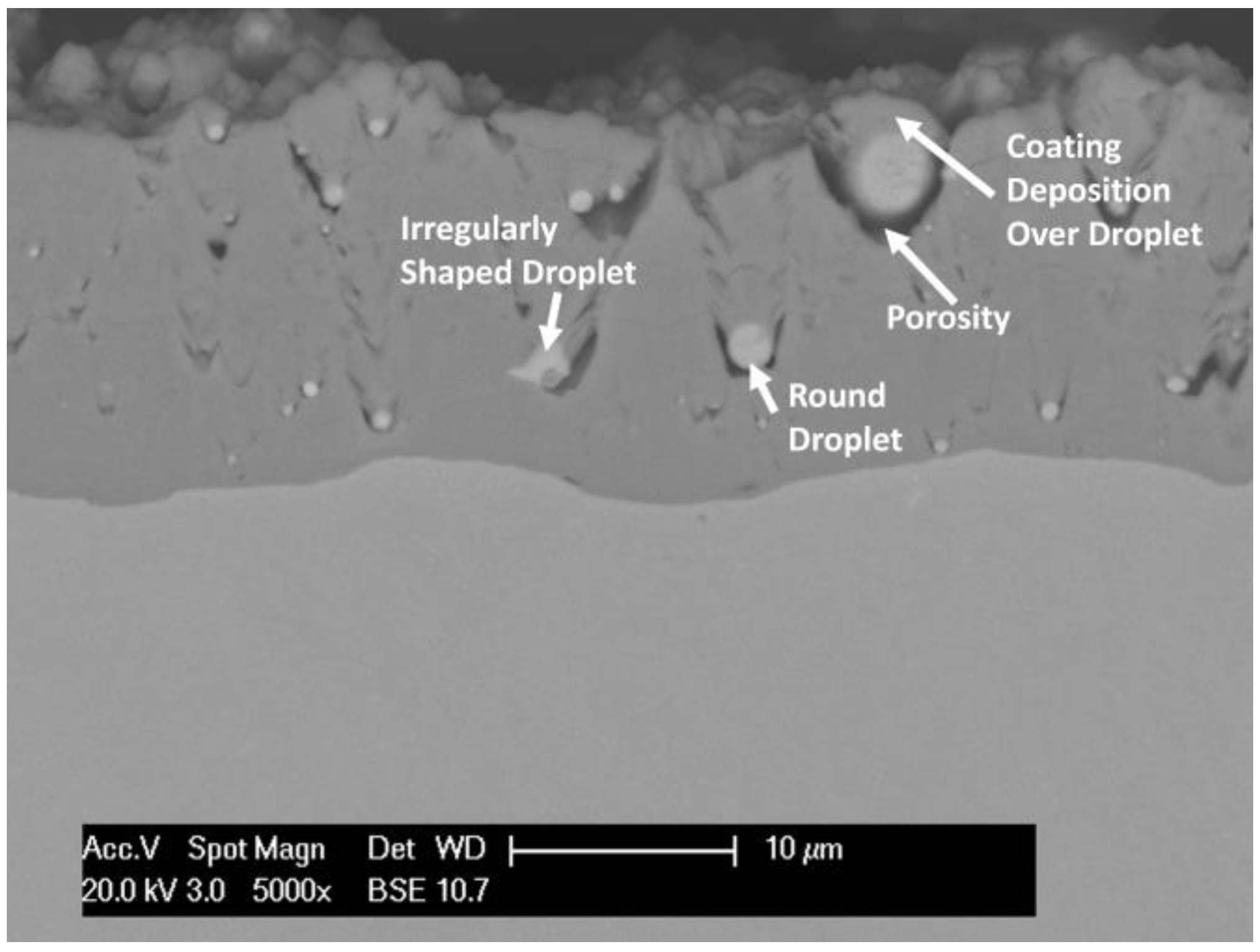
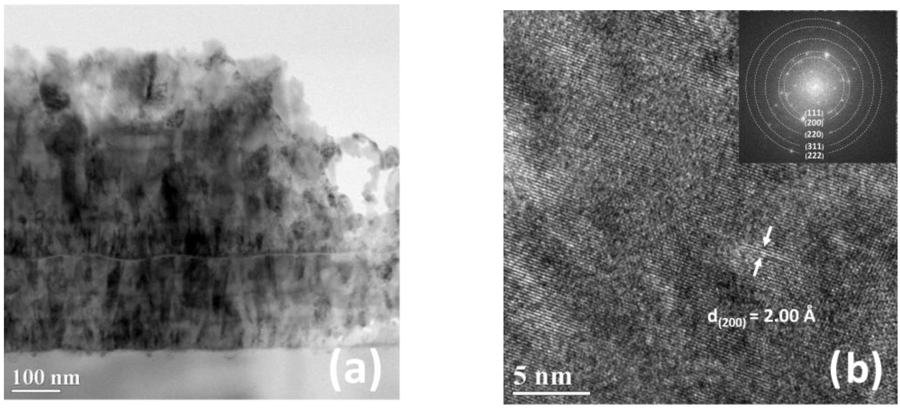
3.1. Microstructural Characterization

Figure 2 shows the surface morphologies of the as-deposited (AlCrTiMoV)N (a) and TiN (b) coatings. The deposited HEA coating has a rough surface, with the measured roughness of 1.04 ± 0.09 μm compared to 0.402 ± 0.08 μm for the TiN coating. The coating cross-sections, shown in Figure 3, illustrate similar average coating thickness of ~16 μm.
Throughout both coating cross-sections, small droplets can be observed. Droplet formation is a well-known defect associated with the CAE process [31]. The cathodic arc discharge produces tiny arcing spots with very high current densities. These spots cause melting of the target surface, forming a melt pool near the arcing spot. The plasma pressure applied onto this melt pool causes liquid material to be ejected from the surface, which then travels across the deposition chamber as droplets. In the case of small droplets, typically less than 1 μm in diameter, they cool during travel and deposit onto the substrate a solid round particle. Larger particles may deposit in a semi-molten state, forming irregular shapes upon impact [31,32]. These droplets may be present throughout the entire coating thickness. The coating will continue to form over the droplets, resulting in a raised surface, contributing to the increased roughness. Droplets can be observed in both the (AlCrTiMoV)N and TiN coatings. However, in the (AlCrTiMoV)N coating, the droplets are more abundant, making up 1.4% of the coating cross-section, compared to the TiN coatings where only a few are visible. Droplets range in size, up to 3.1 µm in diameter in (AlCrTiMoV)N coating. Porosity can also be observed in the surrounding area due to the shadowing effect of the droplet, as shown in Figure 4.
EDS analysis was performed on the (AlCrTiMoV)N coating cross-section. The nitride matrix contains approximately 55% N and the ratio of the metallic constituents in the nitride phase varies from that in the target material. As shown in Table 1, the relative amount of Al and Cr compared to the total metallic elements increased and the remaining elements (Ti, Mo, V) decreased. Increased concentrations of aluminum have been reported from other studies in multicomponent coatings [33]. As shown by the differing contrast in the backscattered electron (BSE) image (Figure 3), the droplets have a different composition from the nitride. The EDS results of the droplets presented in Table 1 suggest that the droplet composition also differs from the target material with noticeably more Ti, Mo and V, corresponding to other works which reported higher concentrations of heavier elements in droplets [15,34]. As shown by the error values presented in Table 1, the nitride composition is consistent across the nitride matrix, while the droplet composition has more variation between droplets. The droplets are also metallic and do not contain nitrogen. During deposition, it is believed that the droplets form a nitride shell, leaving the interior core unreacted [35,36].
The XRD spectra of the (AlTiCrVMo)N and TiN coatings are shown in Figure 5. The (AlTiCrVMo)N coating has a single solid solution nitride phase, with a B1 face-centered cubic (FCC) structure, similar to the TiN coating. The nitride phase has a lattice parameter of 4.139 Å. The formation of a single solid solution is as expected per design due to the increased solid solubility and long-distance diffusion associated with high entropy alloys and the B1 FCC structure is commonly observed in HEA nitride coatings [13]. The diffraction pattern shows strong (111) and (200) peaks along with weaker peaks corresponding to (220), (311) and (222) planes, suggesting that the coating has no strongly preferred orientation. The peak positions of the strongest intensity planes ((111) and (200)) of the B1 FCC structures of the binary nitrides (TiN, CrN, VN) are indicated on the graph, along with the peak positions of the strongest hexagonal close packed (HCP) AlN (101) and tetragonal (Tet) Mo2N (112. The weak peaks at 2θ = 40.7°, 59.0° and 74.2° are from a body-centered cubic (BCC) phase that is associated with the metal droplets. It is not out of expectation since the droplets were composed of a large concentration of the metal elements (Mo, V and Cr) that have BCC structures as noted in Table 1. Based on Scherrer’s equation [37], the average crystallite size of the FCC B1 nitride phase was calculated as 27.7 nm. The XRD spectrum of the TiN coating confirms its B1 structure, with the strongest (111) peak at 2θ = 36.6°, indicating a (111) preferred crystal orientation.
Figure 6 shows cross-sectional TEM images of the (AlCrTiMoV)N coatings. At low magnification (see Figure 6a), the columnar structure can be observed. The layered pattern, parallel to the coating surface, results from the alternate exposure of the samples to the two cathodes during deposition. The image additionally supports the theory that the coating has a single solid-solution nitride phase. Figure 6b presents another high-resolution TEM image of the coating. The measured interplanar distance of the (200) plane of 2.00 Å is shown. The selected area electron diffraction pattern (SAED) (Figure 6b) exhibits the rings corresponding to the (111), (200), (220), (311) and (222) XRD peaks presented in Figure 5 and confirms that the nitride matrix has an FCC B1 structure and that the coating layer does not have any preferred orientation. Unlike the SEM images presented above, no droplets are observed in the TEM images. This is likely due to that fact that TEM looks at a small sampling area, less than 1 μm2 in the figures provided here, which leads to a high probability of no droplets being present. Furthermore, it should be noted that in the SEM images presented above, there are more droplets in the upper sections of the coating, which occurred after a longer deposition time. In Figure 3a, very few droplets are seen in the lower 25% of the coating. The formation of more droplets at the later stage of coating deposition reflects an increasing temperature of the cathode materials with the deposition time. When the cathodes have a high temperature, a relatively larger meting pool can be generated, which facilitates more ejection of macro-particles from the cathodes [32]. The samples prepared for TEM were deposited with a shorter deposition time (70 Ah) than the other samples (300 Ah), reducing the number of droplets being formed.

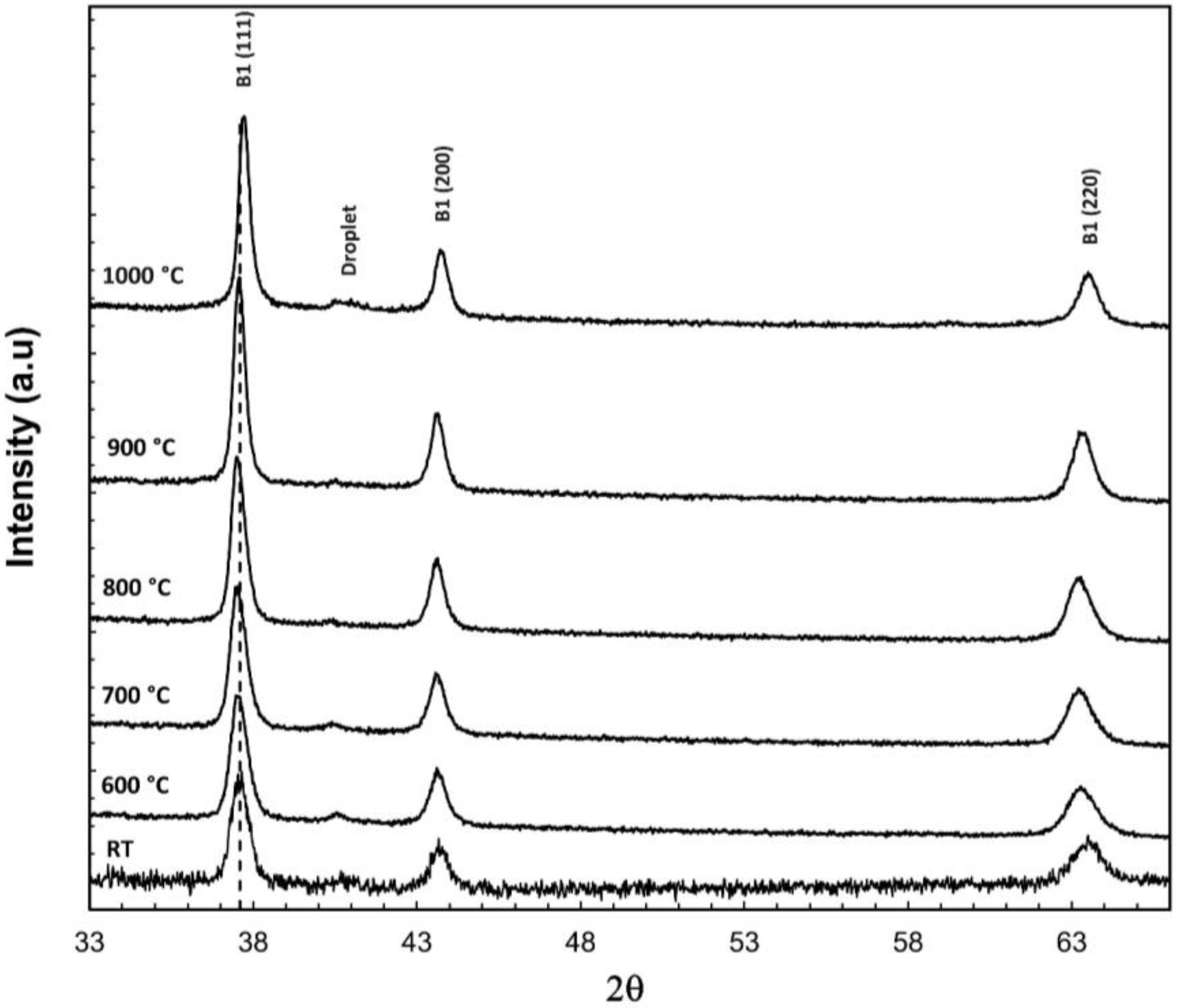
3.2. Thermal Stability

To investigate the thermal stability of the (AlCrTiMoV)N coating, the XRD spectra were also obtained at elevated temperatures; samples were heated to 600 °C, 700 °C, 800 °C, 900 °C and 1000 °C and held for 20 min after heating to each temperature. As shown in Figure 7, there is minimal change in the XRD patterns. No phase decomposition or formation of new diffraction peaks indicates that the nitride crystal structure is stable for temperatures up to 1000 °C. There is no significant change in peak positions when the temperature increased from room temperature to 900 °C, but a peak shift occurred when the temperature was further increased to 1000 °C. There is some peak narrowing as the temperature increases, associated with increasing grain size, from 27.7 nm at room temperature to 37.2 nm after exposure at 1000 °C. The excellent thermal stability is a result of the high mixing entropy and sluggish diffusion associated with HEAs [11].

3.3. Mechanical Properties

The hardness of the (AlCrTiMoV)N matrix was measured by nanoindentation to be 21.3 ± 2.2 GPa, with an elastic modulus of 304 ± 22 GPa. Both the hardness and elastic modulus were lower than those of the TiN coating, which measured as 26.6 ± 0.7 GPa and 417 ± 5 GPa, respectively. Due to their size limitations, the hardness of the droplets cannot be evaluated. However, as a metal phase, the droplets are expected to be softer, thus lowering the coating bulk hardness and potentially impacting the wear and erosion behavior. While the coating nitride has a lower hardness than TiN, both coatings have the same H3/E2 ratio of 0.11, which is commonly used as an indication of resistance to plastic deformation and affecting properties such as wear and erosion resistance [38].

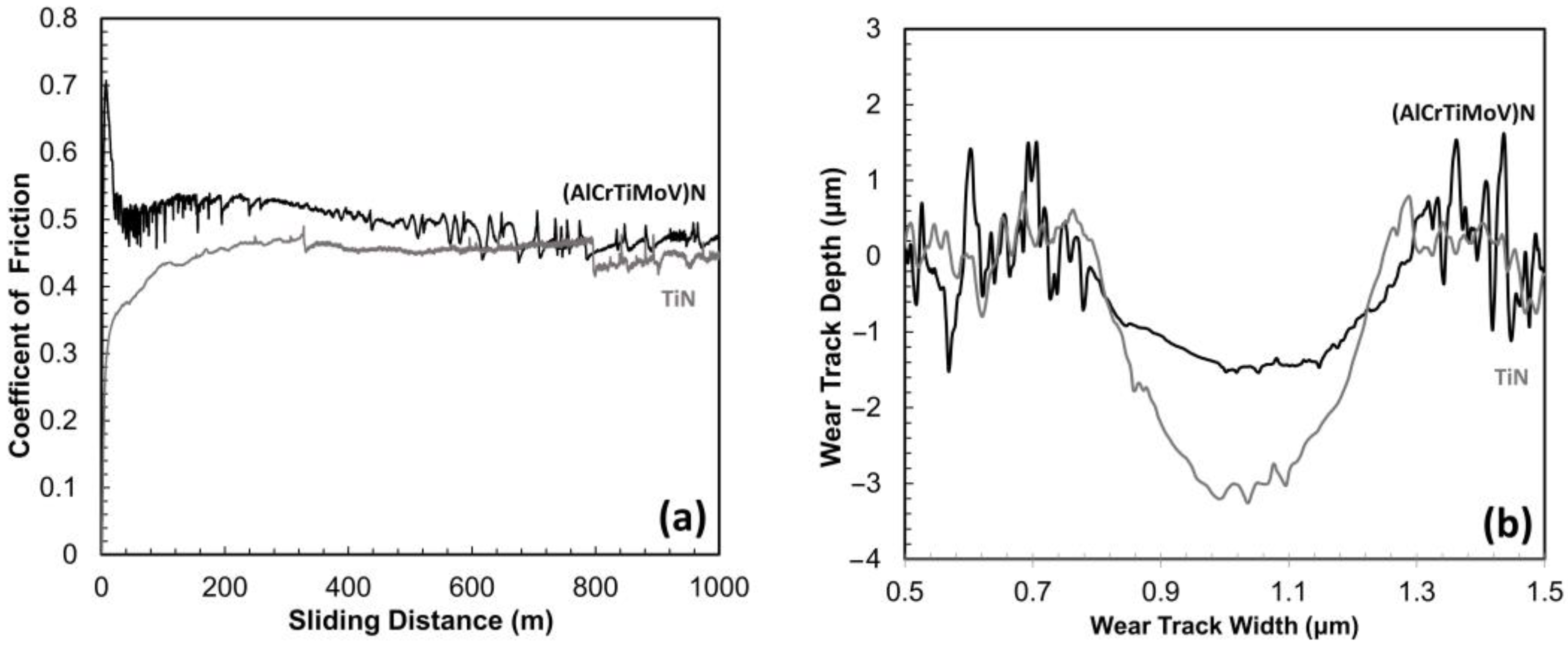
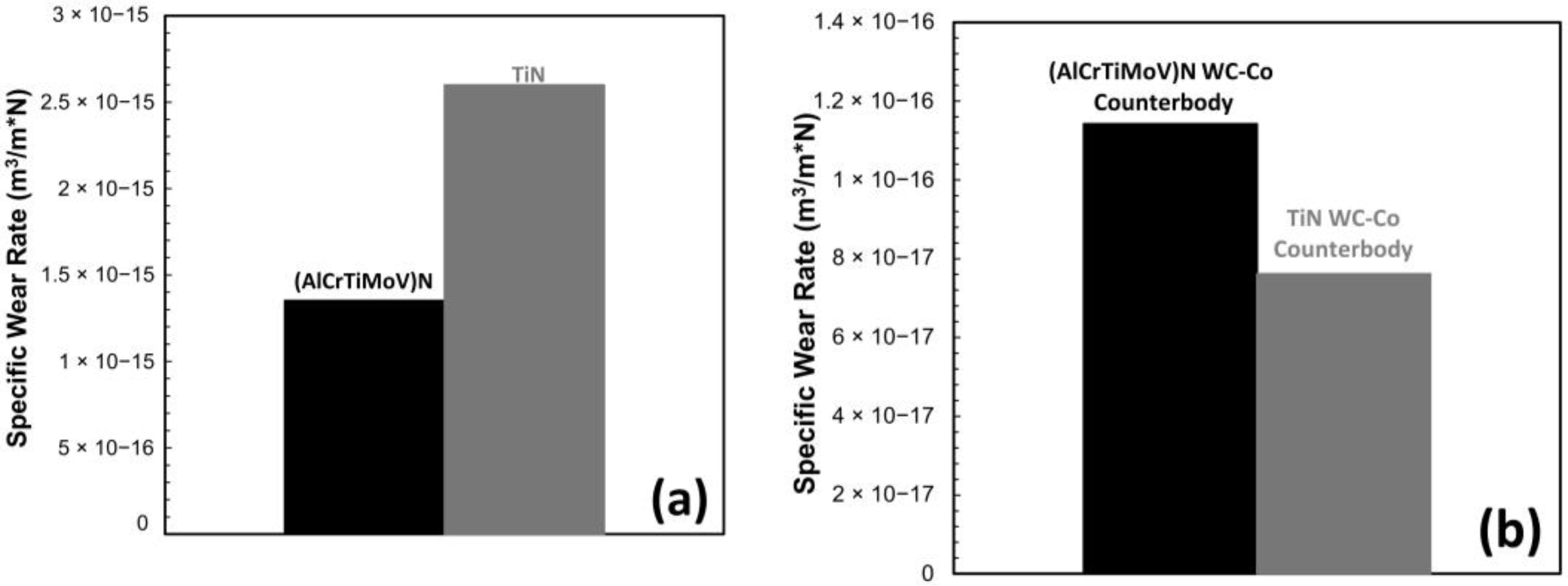
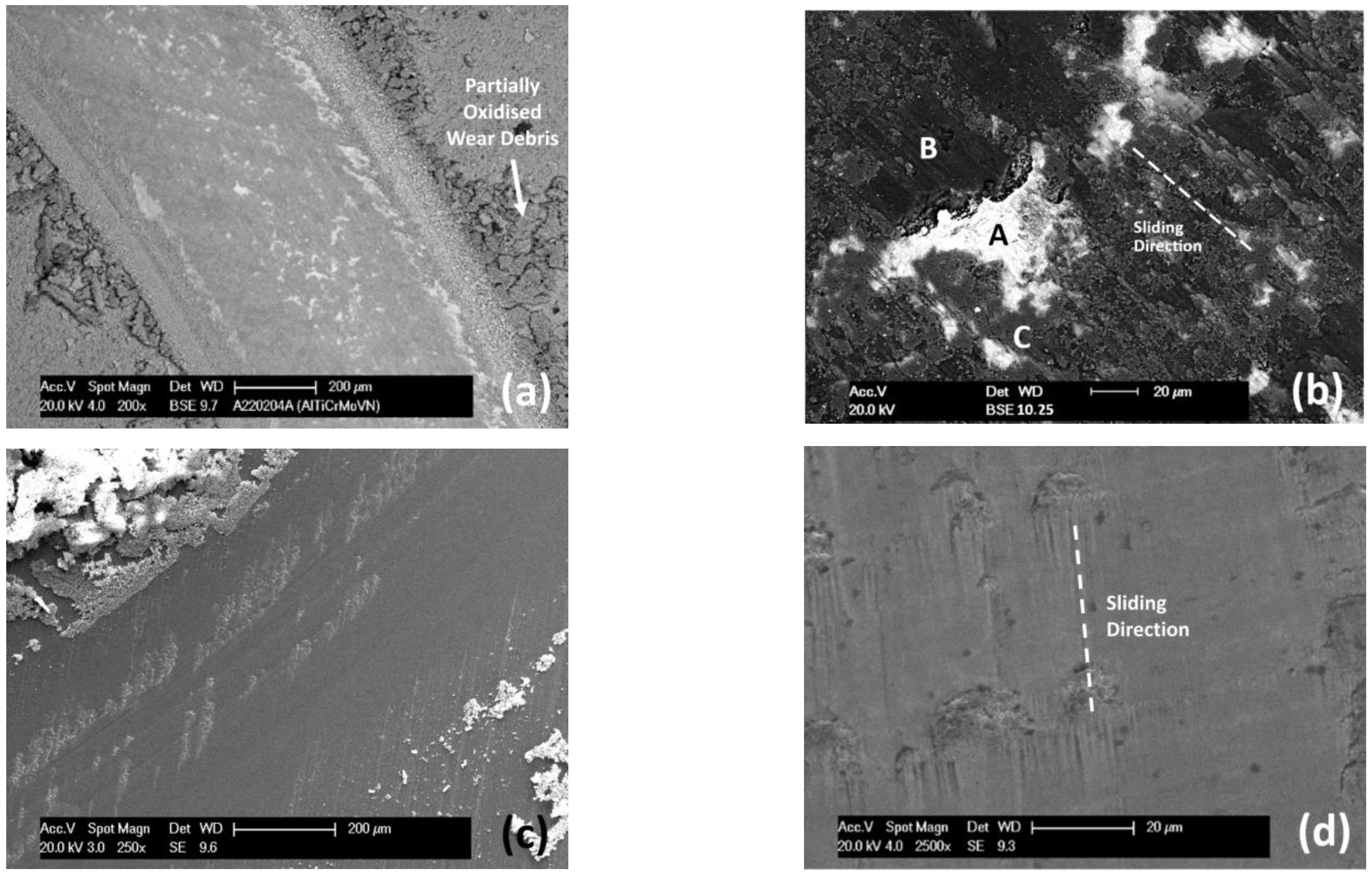
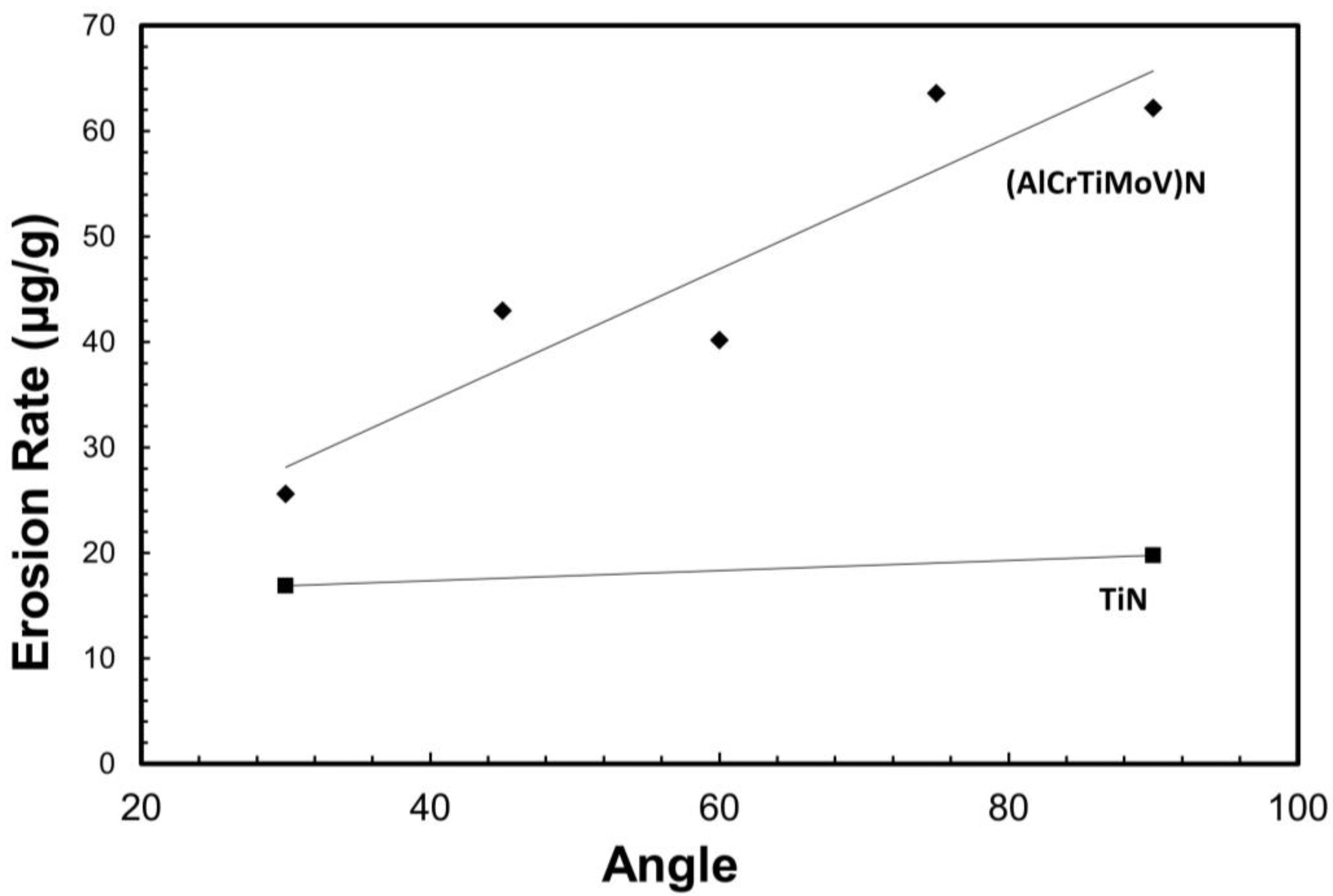
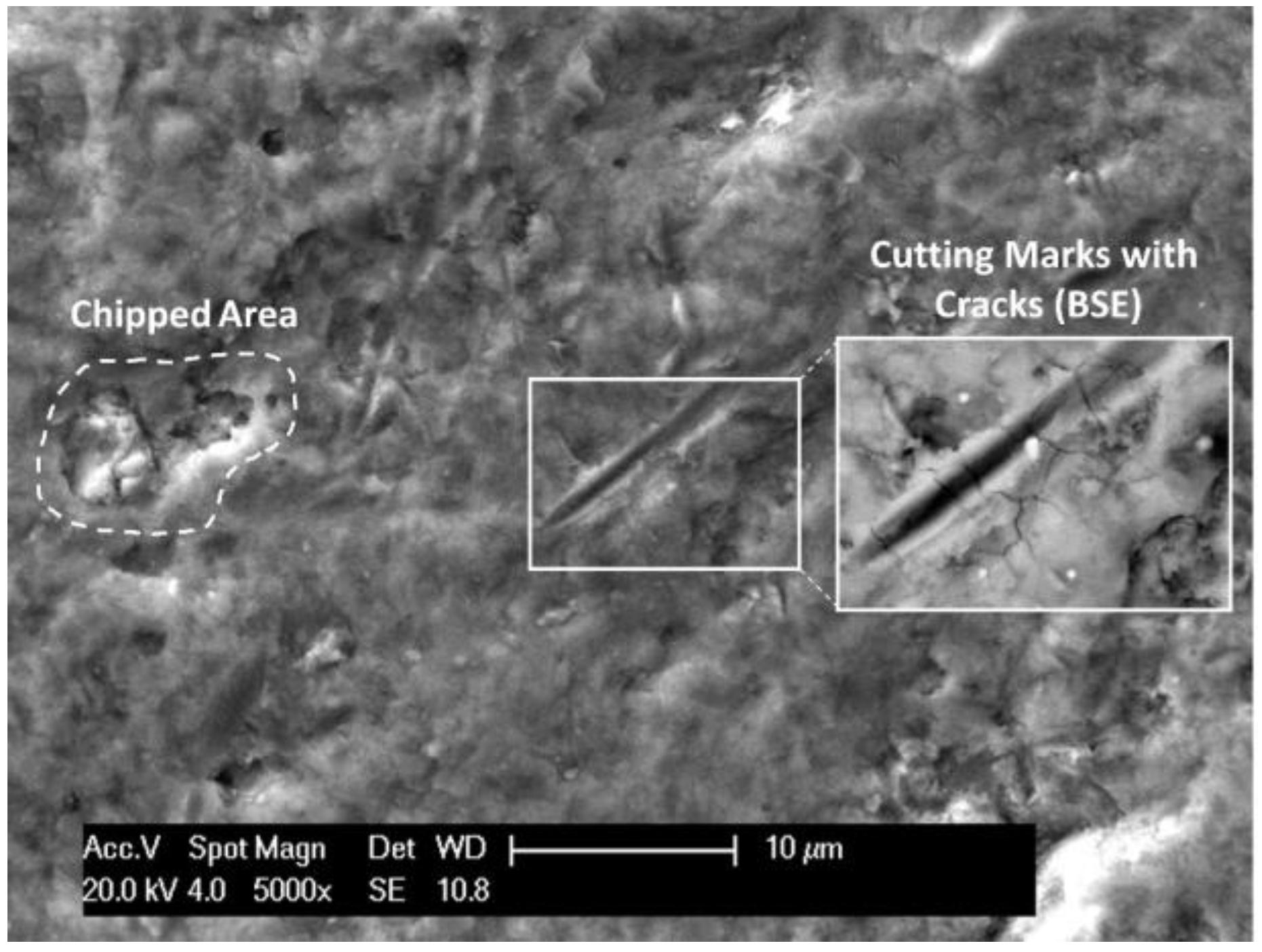
3.4. Wear and Erosion Resistance

The coating was evaluated for its resistance to wear and erosion in order to characterize its in-service performance. As wear and friction are closely related [20], the coefficient of friction was measured throughout the wear test, as is shown in Figure 8a; it peaked rapidly at the start-up then decreased to a steady response, with an average value of 0.49 for the duration of the test. In comparison, that of the TiN coating increased slowly then reaching a steady state value of 0.45 after a sliding distance of 200 m for the remainder of the test. As shown in Figure 8b, after a sliding distance of 1 km the wear track of the (AlCrTiMoV)N coating had an average width of 0.44 mm, similar to that for TiN (0.48 mm), but a markedly shallower depth (1.97 um) than that of the TiN coating (3.40 um). Figure 9 shows the specific wear rates of the (AlCrTiMoV)N, TiN and WC-Co counterparts. The average wear rate of the (AlCrTiMoV)N coating is 1.35 ± 0.7 × 10⁻¹⁵ m3/(N·m), whereas the TiN coating is twice that, at a wear rate of 2.60 ± 0.3 × 10⁻¹⁵ m3/(N·m). It indicates that the (AlCrTiMoV)N high entropy nitride coating demonstrates a better wear resistance than TiN.
Figure 10 shows the wear tracks of both coatings after a sliding distance of 1 km. Figure 10a shows that wear debris is accumulated at the edge of the wear track. EDS analysis presented in Table 2 of the wear debris shows that it is primarily the coating composition with trace amounts of debris from the WC-Co ball and that it has been partially oxidized. Figure 10b shows the detailed morphology of the wear track, which was partially covered by smeared wear debris, as confirmed by EDS results. Area A shows the mixed debris from both the coating material and the WC-Co ball being smeared on the surface. B is an area of coating wear debris, free of any counter body material and oxidized. The area C, s is the nitride matrix. EDS mapping of the wear track (Figure 10b) presented in Figure 11 supports the results in Table 2, showing the differing compositions. Similarly, the TiN wear track, as seen in Figure 10c,d, shows accumulated wear debris adjacent to its wear track; the track, however, looks clean and smooth with a limited area covered with smeared wear debris.
The mass erosion rates of the coatings are presented in Figure 12. The erosion rate of the (AlCrTiMoV)N coating increases as the sand impact angle increases; it increases from 26 μg/g at 30° to 62 μg/g at 90°. In comparison, the erosion rate of TiN increases from 16.9 μg/g at 30° to 19.8 μg/g at 90°. Clearly, the erosion rates of the (AlCrTiMoV)N coating are higher than those of TiN, meaning a lower erosion resistance when compared to TiN.
To investigate the erosion damage mechanisms, the erosion scars were examined under SEM. The erosion scar shows a combination of brittle and ductile damage mechanism where cutting is the dominant erosion mechanism at low angles while cracking/chipping make a significant contribution to the material loss at high angles. As shown in Figure 13, cutting marks are visible at all angles, but become shorter at high angles. Cracking and chipping are also observed, becoming more prevalent and producing longer cracks at higher angles, visible in Figure 14. Embedded alumina (erodent) is also observed in the surface. Figure 15 presents EDS mapping of the erosion scar at 90° impact. As shown in the figure, some alumina and droplets are visible in the upper right corner. Uniform distribution of the target elements indicates that all elements erode evenly.
The detrimental effects of the droplets have also been investigated, confirming that the presence of droplets increases the erosion rate. The circled region in Figure 16 shows an occurrence where the coating was chipped away from a 90° impact. The circular voids in the chipped area are holes which occur on the surface where droplets have been removed due to the impact of sand particles, as the area around the droplet is weakened due to the porosity that facilitates the removal of droplets. The voids/pores can provide an initiation site for further damage and contribute to a higher erosion rate [39,40].
In comparison to some of the studies on HEN coatings discussed above, the (AlCrTiMoV)N coatings investigated in this study showed comparable results [8,9,10,11,12,13,14,15,16,17]. The B1 FCC structure is consistent with the findings presented in this study. Similar findings on thermal stability were reported for (AlCrMoSiTi)N with no decomposition noted after heating to 1173 K for 5 h [10]. The hardness (21.3 GPa) is lower than some HEN coatings (30–40 GPa); however, these would be influenced by other parameters including composition and process parameters. The wear and erosion rates could not be compared as these properties were not evaluated in these studies, which is why the comparison with TiN coatings was used for this paper. In particular, the studies on CAE HEA coatings also identified significant droplet formation during deposition [14,15,16,17]. However, the effect of the droplets on the performance was not considered. The above results from this study highlight the need to reduce droplet formation in the HEA coatings because the droplets have a significant negative effect on the performance. Care should be taken when designing the cathode material. Although high-quality coatings of AlTiN [41] and AlCrN [42] have been produced by CAE, the interelement interactions must be considered for HEA targets. The different atom sizes, while increasing the lattice distortion, may also weaken the interatomic bonding or form a eutectic structure, both of which would reduce the melting temperature of the target material. Alternatively, to reduce droplet formation, measures can be taken to effectively cool the cathodes or to accelerate the arc spot motion to reduce the size of the melt pool [31]. Another approach is utilizing filtering techniques to remove the molten droplets using an electric or magnetic filter [43]. These issues will need to be addressed for CAE to be a viable technique for producing high-quality HEA coatings in future studies.

4. Conclusions

In this study, (AlCrTiMoV)N high entropy nitride coating was prepared by CAE. The resulting coating has a primary single-phased solid solution nitride phase. The coating showed excellent high-temperature phase stability, with no discernible change in structure when being heated up to 1000 °C. The as-deposited nitride had a hardness of 21.3 GPa and an elastic modulus of 304 GPa, lower than those of TiN (26.6 GPa and 417 GPa), but the same H3/E2 ratio of 0.11. The coating contains spherical metallic droplets, which lower the bulk hardness and are believed to detrimentally influence the coating performance. The wear rate of (AlCrTiMoV)N was measured to be 1.35 × 10⁻¹⁵ m3/(m*N), in other words half the wear rate of the TiN coating, showing a better wear resistance than TiN. Sand particle erosion tests showed an increase in the erosion rate with increasing impingement angles: erosion rates of 26 μg/g at 30° to 62 μg/g at 90°, higher than that measured from TiN coating. SEM images of the erosion scar revealed a mixed erosion damage mode with cutting marks, coating cracking and chipping. In summary, the high entropy nitride coating developed in this study exhibited excellent high thermal phase stability, good wear resistance, but reduced erosion resistance when compared with the counterpart TiN coating. Future effort will be dedicated to reducing the droplets defect in order to optimize the mechanical properties, wear resistance and erosion performance of the coating.

Author Contributions

Conceptualization, Q.Y. and X.H.; Formal analysis, A.L. and Q.Y.; Writing—original draft, A.L.; Writing—review & editing, Q.Y. and X.H.; Supervision, Q.Y. and X.H. All authors have read and agreed to the published version of the manuscript.

Funding

This research was funded by the New Ideation Program of the National Research Council of Canada (NRC) under project A1-019042.

Institutional Review Board Statement

Not applicable.

Informed Consent Statement

Not applicable.

Data Availability Statement

Data are available upon request.

Acknowledgments

The authors would like to thank Kayvan Separi, Guy Parent, Xiaohua Wu and Andre Zborowski, all from the NRC, for performing coating deposition, preparing the TEM sample, performing TEM analysis and performing the high temperature XRD analysis, respectively.

Conflicts of Interest

The authors declare no conflict of interest. The funders had no role in the design of the study; in the collection, analyses, or interpretation of data; in the writing of the manuscript; or in the decision to publish the results.

References

  1. Paldey, S.; Deevi, S.C. Single layer and multilayer wear resistant coatings of (Ti, Al)N: A review. Mater. Sci. Eng. 2003, 342, 58–79. [Google Scholar] [CrossRef]
  2. Navinšek, B.; Panjan, P.; Milošev, I. Industrial applications of CrN (PVD) coatings, deposited at high and low temperatures. Surf. Coat. Technol. 1997, 97, 182–191. [Google Scholar] [CrossRef]
  3. Dogan, H.; Findik, F.; Oztarhan, A. Comparative study of wear mechanism of surface treated AISI 316L stainless steel. Ind. Lubr. Tribol. 2003, 55, 76–83. [Google Scholar] [CrossRef]
  4. Chen, J.; Zhou, X.; Wang, W.; Liu, B.; Lv, Y.; Yang, W.; Xu, D.; Liu, Y. A review on fundamental of high entropy alloys with promising high–temperature properties. J. Alloy. Compd. 2018, 760, 15–30. [Google Scholar] [CrossRef]
  5. Wang, J.-J.; Chang, S.-Y.; Ouyang, F.-Y. Effect of substrate bias on the microstructure and properties of (AlCrSiNbZr)Nx high entropy nitride thin film. Surf. Coat. Technol. 2020, 393, 125796. [Google Scholar] [CrossRef]
  6. Tsai, M.-H.; Yeh, J.-W. High Entropy Alloys: A Critical Review. Mater. Res. Lett. 2014, 2, 107–123. [Google Scholar] [CrossRef]
  7. Zhang, C.; Lu, X.; Zhou, H.; Wang, Y.; Sui, X.; Shi, Z.; Hao, J. Construction of a compact nanocrystal structure for (CrNbTiAlV)Nx high-entropy nitride films to improve the tribo-corrosion performance. Surf. Coat. Technol. 2022, 429, 127921. [Google Scholar] [CrossRef]
  8. Lai, C.-H.; Lin, S.-J.; Yeh, J.-W.; Chang, S.-Y. Preparation and characterization of AlCrTaTiZr multi-element nitride coatings. Surf. Coat. Technol. 2006, 201, 3275–3280. [Google Scholar] [CrossRef]
  9. Cui, P.; Li, W.; Liu, P.; Zhang, K.; Ma, F.; Chen, X.; Feng, R.; Liaw, P.K. Effects of nitrogen content on microstructures and mechanical properties of (AlCrTiZrHf)N high-entropy alloy nitride films. J. Alloy. Compd. 2020, 834, 155063. [Google Scholar] [CrossRef]
  10. Hsu, S.-Y.; Lai, Y.-T.; Chang, S.-Y.; Tsai, S.-Y.; Duh, J.-G. Combinatorial synthesis of reactively co-sputtered high entropy nitride (HfNbTiVZr)N coatings: Microstructure and mechanical properties. Surf. Coat. Technol. 2022, 442, 128564. [Google Scholar] [CrossRef]
  11. Chang, H.-W.; Huang, P.-K.; Yeh, J.-W.; Davison, A.; Tsau, C.-H.; Yang, C.-C. Influence of substrate bias, deposition temperature and post-deposition annealing on the structure and properties of multi-principal-component (AlCrMoSiTi)N coatings. Surf. Coat. Technol. 2008, 202, 3360–3366. [Google Scholar] [CrossRef]
  12. Novikov, V.; Stepanov, N.; Zherebtsov, S.; Salishchev, G. Structure and Properties of High-Entropy Nitride Coatings. Metals 2022, 12, 847. [Google Scholar] [CrossRef]
  13. Lewin, E. Multi-component and high-entropy nitride coatings—A promising field in need of a novel approach. J. Appl. Phys. 2020, 127, 160901. [Google Scholar] [CrossRef]
  14. Pogrebnjak, A.D.; Beresnev, V.M.; Smyrnova, K.V.; Kravchenko, Y.O.; Zukowski, P.V.; Bondarenko, G.G. The influence of nitrogen pressure on the fabrication of the two-phase superhard nanocomposite (TiZrNbAlYCr)N coatings. Mater. Lett. 2018, 211, 316–318. [Google Scholar] [CrossRef] [Green Version]
  15. Pogrebnjak, A.D.; Yakushchenko, I.V.; Bondar, O.V.; Beresnev, V.M.; Oyoshi, K.; Ivasishin, O.M.; Amekura, H.; Takeda, Y.; Opielak, M.; Kozak, C. Irradiation resistance, microstructure and mechanical properties of nanostructured (TiZrHfVNbTa)N coatings. J. Alloy. Compd. 2016, 679, 155–163. [Google Scholar] [CrossRef]
  16. Pogrebnjak, A.D.; Yakushchenko, I.V.; Sobol, O.V.; Beresnev, V.M.; Kupchishin, A.I.; Bondar, O.V.; Lisovenko, M.A.; Amekura, H.; Knon, K.; Oyoshi, K.; et al. Influence of Residual Pressure and Ion Implantation on the Structure, Elemental Composition, and Properties of (TiZrAlYNb)N Nitrides. Tech. Phys. 2015, 60, 1175–1183. [Google Scholar] [CrossRef]
  17. Xia, A.; Dedoncker, R.; Glushko, O.; Cordill, M.J.; Depla, D.; Franz, R. Influence of the nitrogen content on the structure and properties of MoNbTaVW high entropy alloy thin films. J. Alloy. Compd. 2021, 850, 156740. [Google Scholar] [CrossRef]
  18. Yang, C.; Jiang, B.; Liu, Z.; Hao, J.; Feng, L. Structure and properties of Ti films deposited by dc magnetron sputtering, pulsed dc magnetron sputtering and cathodic arc evaporation. Surf. Coat. Technol. 2016, 304, 51–56. [Google Scholar] [CrossRef]
  19. Smyrnova, K.V.; Pogrebnjak, A.D.; Beresnev, V.M.; Litovchenko, S.V.; Borba-Pogrebnjak, S.O.; Manokhim, A.S.; Kilmenko, S.A.; Zhollybekov, B.; Kupchishin, A.I.; Kravchenko, Y.O.; et al. Microstructure and Physical–Mechanical Properties of (TiAlSiY)N Nanostructured Coatings Under ifferent Energy Conditions. Met. Mater. Int. 2018, 24, 1024–1035. [Google Scholar] [CrossRef]
  20. Findik, F. Latest progress on tribological properties of industrial materials. Mater. Des. 2014, 57, 218–244. [Google Scholar] [CrossRef]
  21. Altinkok, N.; Özsert, İ.; Findik, F. Dry sliding wear behavior of Al2O3/SiC particle reinforced aluminium based mmcs fabricated by stir casting method. Acta Phys. Pol. 2013, 124, 11–19. [Google Scholar] [CrossRef]
  22. Beake, B.D.; Endrino, J.L.; Kimpton, C.; Fox-Rabinovich, G.S.; Veldhuis, S.C. Elevated temperature repetitive micro-scratch testing of AlCrN, TiAlN and AlTiN PVD coatings. Int. J. Refract. Met. Hard Mater. 2017, 69, 215–226. [Google Scholar] [CrossRef] [Green Version]
  23. Mo, J.L.; Zhu, M.H.; Leyland, A.; Matthews, A. Impact wear and abrasion resistance of CrN, AlCrN and AlTiN PVD coatings. Surf. Coat. Technol. 2013, 215, 170–177. [Google Scholar] [CrossRef]
  24. Lai, Z.; Wang, C.; Zheng, L.; Huang, W.; Yang, J.; Guo, G.; Xiong, W. Adaptability of AlTiN-based coated tools with green cutting technologies in sustainable machining of 316L stainless steel. Tribol. Int. 2020, 148, 106300. [Google Scholar] [CrossRef]
  25. Hung, S.-B.; Wang, C.-J.; Chen, Y.-Y.; Lee, J.-W.; Li, C.-L. Thermal and corrosion properties of V-Nb-Mo-Ta-W and V-Nb-Mo-Ta-W-Cr B high entropy alloy coatings. Surf. Coat. Technol. 2019, 375, 802–809. [Google Scholar] [CrossRef]
  26. Zhang, Y.; Wu, H.; Yu, X.; Tang, D. Role of Cr in the high-temperature oxidation behavior of CrxMnFeNi high-entropy alloys at 800 °C in air. Corros. Sci. 2022, 200, 110211. [Google Scholar] [CrossRef]
  27. Xu, D.D.; Zhou, B.L.; Wang, Q.Q.; Zhou, J.; Yang, W.M.; Yuan, C.C.; Xue, L.; Fan, X.D.; Ma, L.Q.; Shen, B.L. Effects of Cr addition on thermal stability, soft magnetic properties and corrosion resistance of FeSiB amorphous alloys. Corros. Sci. 2018, 138, 20–27. [Google Scholar] [CrossRef]
  28. Feng, C.; Feng, X.; Guan, Z.; Song, H.; Wang, T.; Liao, W.; Lu, Y.; Zhang, F. Nanocrystalline (AlTiVCr)N Multi-Component Nitride Thin Films with Superior Mechanical Performance. Nanomaterials 2022, 12, 2722. [Google Scholar] [CrossRef]
  29. Wen, X.; Yao, H.; Yang, S. Improvement of Sliding Performance for Ball on Disc Tribo-Partners Using Graphite Like Carbon Solid Lubricant Coating. Mater. Sci. Appl. 2018, 9, 191–209. [Google Scholar] [CrossRef] [Green Version]
  30. A. G76-04; Standard Test Method for Conducting Erosion Tests by Solid Particle Impingement Using Gas Jets. ASTM International: West Conshohocken, PA, USA. 2004. Available online: https://www.astm.org (accessed on 15 November 2022).
  31. Vengesa, Y.; Fattah-alhosseini, A.; Elmkhah, H.; Imantalab, O. Influence of post-deposition annealing temperature on morphological, mechanical and electrochemical properties of CrN/CrAlN multilayer coating deposited by cathodic arc evaporation-physical vapor deposition process. Surf. Coat. Technol. 2022, 423, 128090. [Google Scholar] [CrossRef]
  32. Panjan, P.; Drnovšek, A.; Gselman, P.; Čekada, M.; Panjan, M. Review of Growth Defects in Thin Films Prepared by PVD Techniques. Coatings 2020, 10, 447. [Google Scholar] [CrossRef]
  33. Aihua, L.; Jianxin, D.; Haibing, C.; Yangyang, C.; Jun, Z. Friction and wear properties of TiN, TiAlN, AlTiN and CrAlN PVD nitride coatings. Int. J. Refract. Met. Hard Mater. 2012, 31, 82–88. [Google Scholar] [CrossRef]
  34. Kuczyk, M.; Krülle, T.; Zawischa, M.; Kaspar, J.; Zimmer, O.; Leonhardt, M.; Leyens, C.; Zimmermann, M. Microstructure and mechanical properties of high entropy alloy nitride coatings deposited via direct current cathodic vacuum arc deposition. Surf. Coat. Technol. 2022, 448, 128916. [Google Scholar] [CrossRef]
  35. La Grange, D.D.; Goebbels, N.; Santana, A.; Heuberger, R.; Imwinkelried, T.; Eschbach, L.; Karimi, A. Effect of niobium onto the tribological behavior of cathodic arc deposited Nb–Ti–N coatings. Wear 2016, 368, 60–69. [Google Scholar] [CrossRef]
  36. Shiao, M.-H.; Shieu, F.-S. A formation mechanism for the macroparticles in arc ion-plated TiN films. Thin Solid Film. 2001, 368, 27–31. [Google Scholar] [CrossRef]
  37. He, K.; Chen, N.; Wang, C.; Wei, L.; Chen, J. Method for Determining Crystal Grain Size by X-Ray Diffraction. Cryst. Res. Technol. 2018, 53, 1700157. [Google Scholar] [CrossRef]
  38. Yang, Q.; Zhao, L.R.; Cai, F.; Yang, S.; Teer, D.G. Wear, erosion and corrosion resistance of CrTiAlN coating deposited by magnetron sputtering. Surf. Coat. Technol. 2008, 202, 3886–3892. [Google Scholar] [CrossRef]
  39. Cao, X.; He, W.; He, G.; Liao, B.; Zhang, H.; Chen, J.; Lv, C. Sand erosion resistance improvement and damage mechanism of TiAlN coating via the bias-graded voltage in FCVA deposition. Surf. Coat. Technol. 2019, 378, 125009. [Google Scholar] [CrossRef]
  40. Zhang, H.; Li, Z.; He, W.; Liao, B.; He, G.; Cao, X.; Li, Y. Damage evolution and mechanism of TiN/Ti multilayer coatings in sand erosion condition. Surf. Coat. Technol. 2018, 353, 210–220. [Google Scholar] [CrossRef]
  41. Wuestefeld, C.; Rafaja, D.; Klemm, V.; Michotte, C.; Kathrein, M. Effect of the aluminium content and the bias voltage on the microstructure formation in Ti1 − xAlxN protective coatings grown by cathodic arc evaporation. Surf. Coat. Technol. 2010, 205, 1345–1349. [Google Scholar] [CrossRef]
  42. Reiter, A.; Derflinger, V.; Hanselmann, B.; Bachmann, T.; Sartory, B. Investigation of the properties of Al1-xCrxN coatings prepared by cathodic arc evaporation. Surf. Coat. Technol. 2005, 200, 2114–2122. [Google Scholar] [CrossRef]
  43. Anders, A. Approaches to rid cathodic arc plasmas of macro and nanoparticles: A review. Surf. Coat. Technol. 1999, 120, 319–330. [Google Scholar] [CrossRef] [Green Version]
Figure 1. SEM image of Al2O3 sand particles.
Coatings 13 00619 g001
Figure 2. SEM SE surface image of as-deposited (a) (AlCrTiMoV)N, (b) TiN coatings.
Coatings 13 00619 g002
Figure 3. SEM BSE Cross sectional image of (a) (AlCrTiMoV)N coating, (b) TiN coating.
Coatings 13 00619 g003
Figure 4. SEM BSE Defects (droplets, porosity and raised surface) present in coating.
Coatings 13 00619 g004
Figure 5. XRD spectra of (AlCrTiMoV)N and TiN coatings.
Coatings 13 00619 g005
Figure 6. TEM images of the (AlCrTiMoV)N high-entropy nitride coating: (a) low-magnification bright-field image and (b) high-resolution TEM image showing the nitride lattice with the insert showing selected area electron diffraction pattern from the coating layer.
Coatings 13 00619 g006
Figure 7. High temperature XRD of (AlCrTiMoV)N coatings.
Coatings 13 00619 g007
Figure 8. Wear test results showing (a) Coefficient of friction vs sliding distance plots of (AlCrTiMoV)N and TiN coatings, (b) Wear track cross-sections.
Coatings 13 00619 g008
Figure 9. Specific wear rates of (a) (AlCrTiMoV)N and TiN coatings and (b) WC-6%Co ball counterpart.
Coatings 13 00619 g009
Figure 10. SEM images of wear tracks of (a,b) (AlCrTiMoV)N coating, A: Coating and ball debris, B: Coating debris, C: Nitride matrix, and (c,d) TiN coating.
Coatings 13 00619 g010
Figure 11. EDS mapping of (AlCrTiMoV)N coating (Figure 10b).
Coatings 13 00619 g011
Figure 12. Mass erosion rate of (AlCrTiMoV)N coating and TiN coating at 30°–90°.
Coatings 13 00619 g012
Figure 13. Erosion scar of (AlCrTiMoV)N coatings at (a) 30°, (b) 90° with differing length of cutting marks.
Coatings 13 00619 g013
Figure 14. Erosion damage of (AlCrTiMoV)N coating at 90 °. Cutting, chipping and cracking visible.
Coatings 13 00619 g014
Figure 15. EDS mapping of (AlCrTiMoV)N coating after erosion at 90° impact.
Coatings 13 00619 g015
Figure 16. Erosion damage of (AlCrTiMoV)N coating tested at 90° showing chipping and holes left by erosion-removed droplets.
Coatings 13 00619 g016
Table 1. Coating nitride and droplet composition (at%).
Region of CoatingAlCrTiMoVN
Target3020201515-
Nitride matrix17.5 ± 0.210.6 ± 0.17.4 ± 0.14.0 ± 0.15.9 ± 0.154.6 ± 0.4
% Change of metallic elements from target to nitride
8.6%

3.2%

−3.7%

−6.2%

−1.9%
-
Droplet15.7 ± 5.99.6 ± 3.728.1 ± 2.218.4 ± 1.328.2 ± 6.20
Table 2. EDS analysis of (AlCrTiMoV)N wear track from Figure 10a,b (at%).
Region of CoatingAlCrTiMoVNOCoW
(a) Wear debris10.76.75.02.43.925.344.90.11.0
(b) A: Coating and ball debris4.84.13.02.22.4075.01.37.2
(b) B: Coating debris8.27.05.44.04.3068.80.31.9
(b) C: Nitride matrix13.712.59.56.46.951.0000
Disclaimer/Publisher’s Note: The statements, opinions and data contained in all publications are solely those of the individual author(s) and contributor(s) and not of MDPI and/or the editor(s). MDPI and/or the editor(s) disclaim responsibility for any injury to people or property resulting from any ideas, methods, instructions or products referred to in the content.

