1. Introduction
Copper-steel composite laminates combine the excellent electrical/thermal conductivity of pure copper with the high strength and corrosion resistance of steel, and have a wide application in many fields, such as nuclear island cooling systems, vacuum chamber heat exchange systems, copper electrolytic refining equipment [
1,
2,
3]. Good metallurgical bonding of copper and steel has been challenging due to the large melting point difference and low mutual solubility. Traditional copper/steel composite laminate preparation methods mainly include accumulative rolling [
4], diffusion welding [
5], magnetron sputtering [
6], and casting [
7]. Compared with the processes mentioned above, explosive welding is an effective process to weld two or more dissimilar laminates, when there are distinct differences in metal properties such as melting point, strength and so on [
8]. Explosive welding is a metallurgical process that uses the shock wave generated by the explosion of explosives to subject the metal to a high-speed impact and bond it in a short period of time. Of course, there are many factors that can affect the quality of welding, such as the falling speed of the flyer plate, static angle, bending angle, burst speed of the explosive, the thickness and nature of the flyer plate and substrate [
9,
10].
The bonding interface has a decisive influence on the mechanical properties of the welded composites. This is because failure often occurs near the weld interface. The development of industry also places higher desire on explosive welding: (1) revealing failure mechanisms of composite materials at the welded interface; (2) improving the bonding strength of welded composite materials.
Presently, most studies on explosive welding are focused on the wave morphology, bonding strength, and microstructure at the interface of two welded dissimilar metals [
10,
11,
12]. The bonding interface of explosive welding is often wavy, and the periodic fluctuation of shear stress is considered to be an important factor [
13]. Gao et al. [
14] investigated the effect of stand-off distance on the bonding strength and microstructure of Al/Ni sheets, and found that with the increasing of stand-off distance, the welded interface becomes more undulating, showing in turn straight, wavy and continuously melted. Zhou et al. [
8] employed tensile shear test with in-situ scanning electron microscope (SEM) to investigate the interfacial bonding properties of the Q235/TA2 composite plate and micro-cracks generation and propagation in the welded interface. The results suggested that failure of the interface is the combination of the cavities, micro-cracks, and brittle intermetallic compounds. Under the tensile-shear condition, micro-cracks develop at the welded interface, associate, and subsequently develop along the interface wave direction. In order to increase the interfacial bonding of explosive welding, friction stir processing (FSP) was used as a means of optimization [
11]. The FSP not only reduces defects at the interface, but introduces the formation of nano-grains during stirring, which significantly improves the bonding strength of the interface. Ismail et al. [
15] found that the addition of carbon nanotubes (CNTs) between two plates increases the resistance of the solder joint to the blast wave. Based on the above studies, it can obviously be found that many efforts were devoted to exploit the interfacial microstructures and improve the interface bonding strength for the explosive welded composite with two kinds of dissimilar metals. In general, relatively little effort has been devoted to fabricate multi-layered composites via explosive welding, especially for a widely used copper-steel composite, while the microstructure and properties of the weld interfaces are worth exploring.
In this work, a three-layered copper/Q235 steel/copper block was fabricated by an explosive welding technique. The interfacial microstructure and shear behavior of the copper/Q235 steel/copper block were clearly explored and revealed.
2. Experimental
Ordinary carbon structural steel plates (Q235, C-0.125, Si-0.072, Mn-0.145, P-0.017, S-0.015, Fe-balance in wt.%) and pure copper (Fe-0.003, Si-0.028, S-0.004, Cu-balance in wt.%) plates were selected. All plates had the same dimensions in 110 × 110 × 3 mm
3. The commonly used parallel type preparation was employed to prepare copper/Q235 steel/copper composite as schematically revealed in
Figure 1a above and all explosions took place in a sand pool. An ammonium nitrate fuel oil (ANFO) mixture having a density of 0.90 g/cm
3 was selected as the explosive material. The explosive material with a detonation velocity of 2200 m/s and a thickness of 65 mm was placed on a Cu plate. The stand-off distance was 6 mm. Under the action of the explosion, the flyer plate near the detonation point was accelerated to collide with the lower plate at an angle and forming a welded interface, as shown in
Figure 1a below. After explosive welding, the thicknesses of the three plates from top to bottom were ~2.65 mm (copper), ~2.9 mm (Q235 steel) and ~2.9 mm (copper), respectively, two interfaces were referred to as upper-interface and lower-interface.
The mechanical properties and microstructure of explosion welded composites tend to differ along the direction of explosive wave propagation, especially the position near and far from the detonation point. Therefore, the samples used in this experiment were strictly cut from the same position of the composite. All mechanical tests and microstructure observations were performed on samples cut in the direction perpendicular to explosion direction from laminates.
X-ray diffraction (XRD) measurements were carried out on a Bruker AXS D8 diffractometer with Cu Kα radiation. The 2θ angle was selected from 40° to 100° and the scanning speed was 6° min−1. Electron back-scattered diffraction (EBSD) analysis was performed on a field emission SEM (Quant 250FEG, FEI, America) equipped with a fully automatic Oxford Instruments Aztec2.0 EBSD system (Channel 5 Software, Oxford Instruments, England, Oxford). The scanning step size and accelerate voltage were 1.5 μm and 20 kV, respectively. The fracture surfaces of specimens were also investigated by this equipment.
The tensile-shear tests on the explosion-welded upper-interface and lower-interface were performed using an AGS-X100KN electronic universal tester (Shimadzu, Kyoto, Japan) with a movement speed of 1 mm/min. Tensile-shear specimens with a thickness of 1 mm were cut as parallel to the bonding interface from the explosively welded copper and Q235 steel plates by wire-electrode cutting and processed according to the standard of American Society for Testing and Materials (ASTM A265-03), as shown in
Figure 1b,c. The specimens were notched with a width of 1 mm at two edges. It should be noticed that in this study, the form of the interface close to the explosive layer varies more significantly with the upper copper plate than with the interface far from the explosive layer. Both shear strength of the upper-interface and lower-interface of the bonding composites were considered in this work. During tensile-shear tests, the load was continuously applied to the specimen until failure fully occurred.
3. Results and Discussion
As shown in
Figure 2a,b, the metallographic results of the initial microstructure indicate that pure copper has equiaxed grains with a mean size of ~17 μm, and Q235 steel (mean grain size of ~14 μm) is composed of a homogeneous mixture of ~90% ferrite (white part in
Figure 2b) and ~10% pearlite (black part in
Figure 2b). It is well known that pearlite is a mechanical mixture of alternating lamellar ferrite and Fe
3C [
16,
17]. According to the XRD results (
Figure 2c), there is no other types of tissue in the matrix of both pure copper and Q235 steel. It should be noted that by comparing the PDF card (PDF#06-0696), the four diffraction peaks in the figure corresponded to the (110), (200), (211) and (220) diffraction peaks of the ferrite. This is mainly because the Fe
3C in the matrix was too small, so there was no obvious diffraction peak. The XRD results for the ND (normal direction of rolling) plane of the copper plate are shown in
Figure 2c (marked in red). Compared with the XRD spectra of standard annealed copper (PDF#65-9743), it can be found that the (110) and (100) diffraction peaks at the ND plane have an increased percentage of intensity. This is attributed to the fact that copper sheets in the rolled state usually have a strong brass texture ({110}<112>) which indicates that the {110} crystalline plane parallel to the ND plane and the <112> crystal direction parallel to the RD (rolling direction). After annealing treatment, although the grains recrystallize and become equiaxed, part of the crystallographic orientation of grains is inherited [
18].
Figure 3a shows the metallographic results of the welded sandwich copper/Q235 steel/copper composites which indicates that the bonding interfaces have high quality joining without defects in forms of pores and micro-cracks. As with other other explosively dissimilar welded joints [
2,
19,
20], upper-interface and lower-interface both have wavy morphology. When the explosion energy is certain, with the increase in stand-off distance, straight, wavy and continuously melted interface will be obtained in order [
14]. The flyer plate is in an accelerated state before it touches the substrate, thus, when the stand-off distance is larger, the kinetic energy of the flyer plate will be transformed into heat energy near the interface [
3,
11,
14]. Such sinusoidal shape of the interfaces can hinder the propagation of cracks and increase the strength of the welded dissimilar layers [
20,
21]. The upper-interface is more undulating than the lower-interface, and the measured average wavelength and amplitude of the upper-interface waves are 290 ± 20 μm and 75 ± 5 μm, respectively, those of the lower-interface are 231 ± 18 μm and 41 ± 3 μm. It may be due to the fact that the upper-interface has higher energy. In addition, there is a small amount of penetration at the upper interface, and it can be found from the energy dispersive X-ray detector (EDX) results (marked by black arrows in
Figure 3b). This phenomenon suggests that the vortex is a melted zone. This could be attributed to the following reasons. Despite the fact that the copper has a very high value of heat conductivity, there was not enough time for the heat generated by the collision to be transferred to other position with lower temperatures at the moment of the explosion. The rapidly increasing temperature resulted in part of the copper and Q235 steel in the bonding interface to melt. The melting points of copper and steel are 1083 °C and 1500 °C, respectively. As a result, a number of the most severely deformed copper microstructures melted in the first place, and more liquid copper was mixed with the soften or even molten iron, which can be evidenced by the fact that copper occupies more volume fraction in the vortex region. Then, under the action of the shock wave, the molten copper and steel mixed together and flowed with the wave crest, and finally converge to the vortex region where the pressure in front of the wave is lowest [
1,
16,
19]. Greenberg et al. [
22,
23] found the same phenomenon in aluminium–tantalum and copper–titanium explosive welding interfaces, vortex zones are formed near the cusps and valleys. Due to the low impact energy, we did not find a similar vortex zone at the lower-interface, as shown in
Figure 3c.
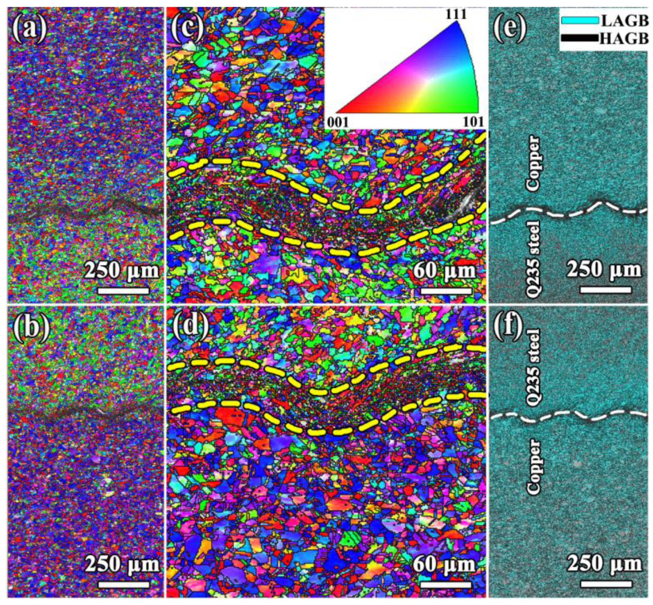
For further understanding, the upper-interface and lower-interface are analyzed by EBSD, as shown in
Figure 4.
Figure 4a,b displays the microstructures of two interfaces. Inverse pole figure (IPF) indicates that the grains away from the interface in copper and steel are equiaxed, and the grain size is consistent with the metallographic statistics. However, the grains of steel have a certain selective orientation with <100> and <111> oriented parallel to the direction of the wave crest line. This could be the inheritance of the initial microstructure, considering the strain gradient distribution at the interface due to the explosion [
12]. Two typical areas are selected and enlarged in
Figure 4c,d, respectively. The upper-interface and lower-interface are composed of ultra-fine grains (UFGs) with thicknesses of ~80 μm and ~50 μm (the area marked by the yellow dotted line). The average grain size of UFG in domains of upper-interface and lower-interface are ~3.6 μm and ~4.8 μm. Different from conventional welding techniques, the copper/Q235 steel interface obtained via explosive welding without the appearance of coarse grains with poor-strength which are often the site of cracks sprouting and eventually severely degrade the mechanical properties of the welded interface. The formation of UFGs can be ascribed to the high temperature generated during the impact at the bonding interface and subsequent rapid cooling. The distribution of grain boundaries in
Figure 4e,f suggests that the UFGs mainly contain high angle grain boundaries (HAGBs), while the density of low angle grain boundaries (LAGBs) is higher beyond the interface and decreases with increasing distance. Which is consistent with the decrease in hardness gradient along the weld interface reported in Liu et al. [
12] and Zhou et al. [
8]. Because high dislocation density and reduced grain size often lead to high hardness [
24,
25].
To investigate the interfacial bonding strength of the copper/Q235 steel/copper explosive composite, the tensile-shear test was employed, and the load-displacement curves are shown in
Figure 5. It can be found that the trend of the tensile-shear curve of the upper-interface is basically the same as that of the lower-interface. Shear strength (
) is commonly used to measure the ability of a material to resist shear sliding, which is defined as
, where
and
are the maximum load and bonding surface area between the two notches [
8]. The corresponding shear strengths of the upper-interface and lower-interfaces are higher than ~235 MPa and ~222 MPa, respectively. However, the energy consumed by the upper-interface and lower-interfaces is also almost equal during the tensile shear test because the area enclosed by the tensile-shear curve and the displacement axis is proportional to the energy consumed by the specimen during the deformation process [
26,
27].
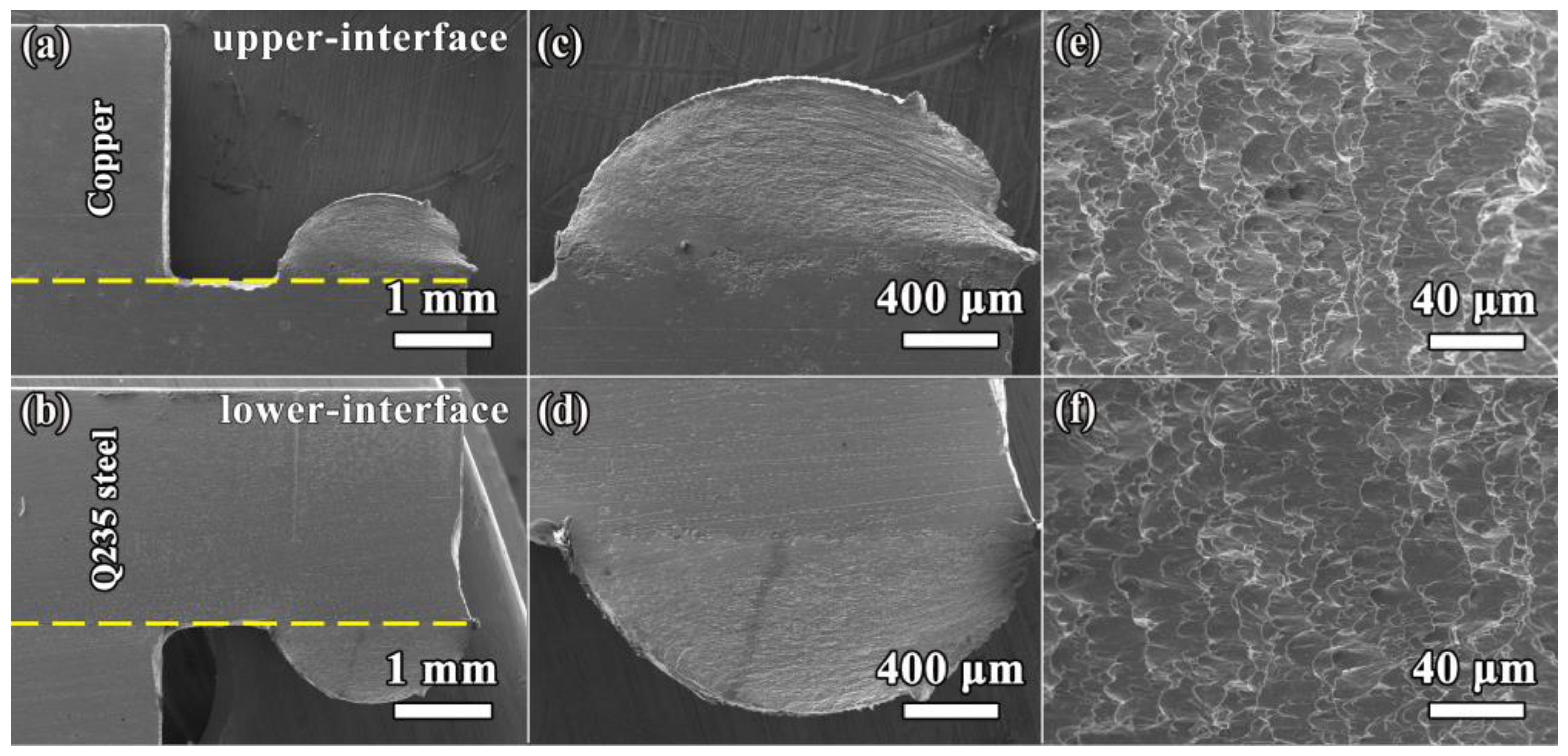
Interestingly, the welded interfaces in the present work exhibited a different fracture behavior during tensile shear testing than in other literature [
8,
14]. Usually, failure of the welded interface occurs along the direction of the interface wave. This is due to the presence of defects such as cavities, cracks and brittle intermetallic at the interface zone. The discontinuities and stress concentration points can weaken the interface shear resistance [
8]. However, during the experiment in this work, all fracture occurs on the copper side, the interface of the welded joint maintains the shape before the shear test (
Figure 5). Fracture on the copper side indicates that the tensile-shear test is failed. In addition, the plastic deformation on the copper side resulted in much more slip traces and surface relief than the steel side which indicates that the plastic deformation during the tensile-shear test occurred mainly on the copper side. The reason for this phenomenon is that pure copper has a low strength. In other words, the shear strength of the upper-interface and lower-interface is much higher than 220 MPa. No obvious micro-cracks and fragmented brittle intermetallic compounds were found at the fracture (
Figure 6a–d). From
Figure 6c,d, it can be found that the plastic deformation on the copper side mainly occurs away from the interface, which is due to the fact that the UFGs can increase the coordination of plastic deformation in the local area and inhibit the generation of micro-cracks [
26,
27]. Thus, the explosive welding interface obtained in this work is excellent. This can also be judged from the fracture morphology of the fractured samples, where a large number of dimples indicate that ductile fracture occurred, and the size of the dimples is comparable to the grain size counted by EBSD, as shown in
Figure 6e,f. Good quality of interfacial bonding will reduce the tendency of interfacial delamination in subsequent plastic processing [
2].
.jpg)


 ,
, 


