Article

Phase Composition, Hardness, and Thermal Shock Properties of AlCrTiN Hard Films with High Aluminum Content

1
College of Mechanical Engineering, Shenyang University, Shenyang 110044, China
2
Key Laboratory of Research and Application of Multiple Hard Films, Shenyang 110044, China
*
Author to whom correspondence should be addressed.
Coatings 2023, 13(3), 547; https://doi.org/10.3390/coatings13030547
Submission received: 1 February 2023 / Revised: 25 February 2023 / Accepted: 27 February 2023 / Published: 3 March 2023
(This article belongs to the Special Issue Structure and Phase Transformations in Thin Films)

Abstract

:
TiCrAlN hard films based on TiN or CrN show superior properties in terms of hardness, wear resistance, and thermal stability due to the addition of alloying elements. AlCrTiN films based on AlN may have higher thermal shock properties, but the knowledge of AlCrTiN films with high Al content has been insufficient until now. In this study, two sets of AlCrTiN hard films with different Al contents of 48 at.% and 58 at.% among metal components were prepared via multi-arc ion plating so as to investigate the effect of Al content on the phase composition, hardness, and thermal shock resistance of the films. The same microstructures, morphologies, and thicknesses of the fabricated film samples were achieved by changing the combination of cathode alloy targets and adjusting the arc source current during deposition. The surface chemical composition, cross-sectional elemental distribution, microstructure, morphology, phase composition, surface hardness, film/substrate adhesion strength, and thermal shock performance of the AlCrTiN films were examined. The obtained results reveal that the two sets of AlTiCrN hard films are face-centered cubic solid solutions with a columnar fine grain structure and a preferred growth orientation of (200) crystal plane. The hardness of the AlCrTiN films can be improved up to HV2850 by properly reducing the Al content from 58 at.% to 48 at.%. Meanwhile, the film/substrate adhesion performance is strong enough in terms of critical loads greater than 200 N. Furthermore, the AlCrTiN films maintain high thermal shock resistance at 600 °C when the Al content decreases from 58 at.% to 48 at.%. The optimal composition of the AlCrTiN hard films is 25:13:15:47 (at.%), based on the consideration of hardness, adhesion, and thermal shock cycling resistance. This optimal AlCrTiN hard film can be suggested as an option for protective coatings of hot process die tools.

1. Introduction

Nitride hard films have been extensively studied and developed for the application to cutting tools. In ternary nitride hard films, such as AlCrN, AlTiN, and CrTiN, the atomic substitution of metal components produces substitutional solid solution (MxMy)N nitride films, which cause lattice distortion and thus increase the film hardness. From the perspective of solid solution strengthening, when the crystal structure remains single phase without forming second phase, the larger the lattice distortion caused by the increase in the solute fraction, the more apparent the strengthening effect. Based on the stoichiometric chemical ratio of a (MxMy)N-type nitride film, the maximum solution strengthening hardness can be obtained at a molar ratio of the metal components close to 1:1 [1,2,3]. When accompanied by a crystal lattice distortion, the preferred crystal growth orientation and even phase composition of the film may also change [4,5].
To increase the hardness of TiN-based ternary nitride films and optimize their comprehensive properties, a third metal component is often added to form a quaternary substitutional (TiXMYMZ)N nitride solid solution hard film. For example, TiAlCrN, TiAlZrN, and TiAlNbN hard films generally exhibit high hardness and good comprehensive properties [6,7,8,9,10,11]. In consideration of the strong effect of Al on the oxidation resistance of Al-contained nitride hard films and the service requirements for nitride hard films as protective coatings of tools and molds, the thermal shock resistance of these films directly affects their actual utilization [12,13]. In fact, most studies on TiAlCrN hard films examined CrN-based and TiN-based films, while relatively few reports focused on AlCrTiN hard films with high Al contents.
Moreover, studies on AlCrN and AlTiN hard films with high Al content have shown that the AlN content up to 60–70 mol.% in Ti1−xAlxN or Cr1−xAlxN single solid solution phase with face-centred (fcc) cubic lattice can be retained without an occurrence of hexagonal close-packed (hcp) structure [14,15,16]. Additionally, the hardness of AlCrN and AlTiN hard films with fcc structure was generally larger than that with (hcp) structure. Similar results were also validated in the study of AlCrTiN hard films [8,17].
The present work aims to investigate the effects of Al content among metal components and Ti/Cr ratios on the phase composition, hardness, film/substrate adhesion strength, and thermal shock properties of AlCrTiN solid solution hard films with fcc structure. Through the deposition process design of multi-arc ion plating technology, different combinations of cathode arc source targets were selected, and the corresponding arc source current was adjusted to ensure the basic consistency of the fabricated film samples in terms of their surface morphology, cross-sectional morphology, N content distribution, and film thickness. Additionally, the deposition process was designed to ensure the Al contents among metal components in AlCrTiN hard films were less than 60 at.% so as to fabricate AlCrTiN solid solution hard films with fcc structure.

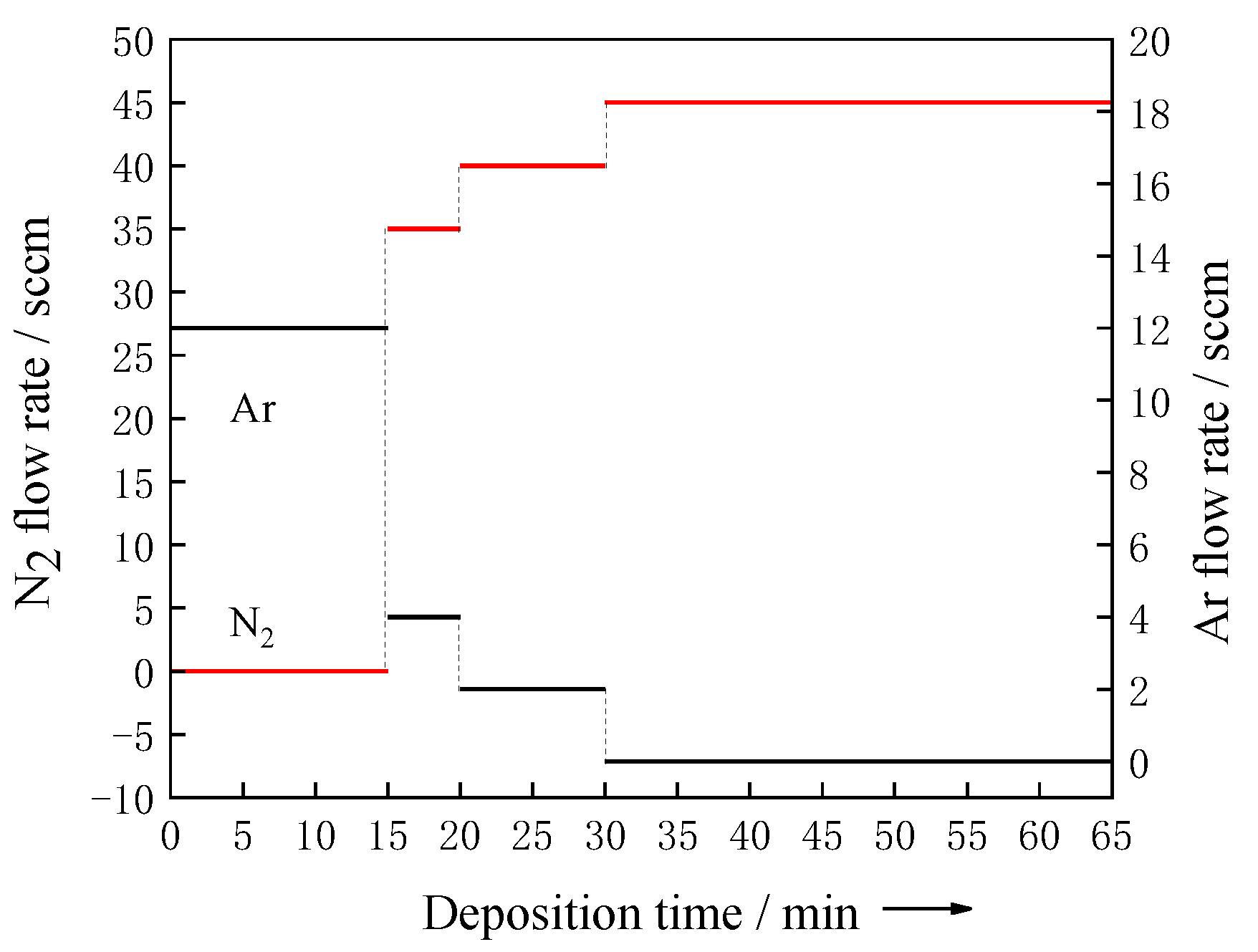
2. Materials and Methods

AlCrTiN hard films were prepared via multi-arc ion plating (MAD-4B) on high-speed steel (W18Cr4V, HRC63-64) substrates [18]. The co-deposition of AlCr and AlTi dual-arc source alloy targets (99.95% purity) with various compositions was performed to ensure the comparability of the deposited AlCrTiN hard films. The two arc source target currents were combined in different proportions to vary the film compositions, while other deposition parameters, such as the gas flow (pressure), deposition time, and deposition temperature, remained the same so as to ensure the basic consistency of the fabricated film samples in terms of their surface morphology, cross-sectional morphology, N content distribution, and film thickness. The coated samples were marked as 1#–6#, as shown in Table 1.
Double-target arc prebombardment was performed at a relatively high negative voltage bias (320–350 V) in an Ar atmosphere (3.0 × 10⁻¹ Pa) for 10 min to clean the substrate and thus increase the film adhesion strength. The initial temperature of the arc bombardment process was 180 °C. After that, an alloy transition layer (deposition time: 5 min, bias voltage drop: −180 V), low N2 flow film (deposition time: 10 min, bias voltage: −180 V), and normal N2 flow film (deposition time: 35 min, bias voltage: −180 V) were obtained (Figure 1). The vacuum chamber temperature at the end of the entire deposition process was 200 ± 10 °C.
Surface morphologies and compositions, cross-sectional morphologies, and elemental distributions of the as-deposited AlCrTiN films were observed with the aid of field-emission scanning electron microscopy (FE-SEM, S-4800) combined with energy-dispersive X-ray spectroscopy (EDS). Phase compositions of the as-deposited films were determined by X-ray diffraction (XRD, X’PertPRO) at a voltage of 40 kV, current of 40 mA, and wavelength (Cu-K α) of 0.154056 nm. The scanning angle (2θ) varied from 20° to 90° at a rate of 0.02°/min and step size of 0.05°. The obtained XRD data were analyzed by the Jade and Origin data processing software. The hardness of the as-deposited films was measured by performing Vickers micro-indentation tests (402 MVD). Three positions in the same field of view were tested at a load of 0.25 N for 20 s.
The film/substrate adhesion strengths of the prepared AlTiCrN films were determined by a WS-2005 automatic scratch tester. The maximum limit of the test load was 200 N, the loading rate was 200 N/min, the scratch speed was 4 mm/min, and the scratch length was 4 mm. A dynamic load method was used during testing, and an acoustic emission signal was recorded. The surface of each prepared sample film was examined by conducting 3–5 scratch tests.
Thermal shock tests were performed at 600 °C in a box-type electrical resistance furnace. A film sample was placed in the uniform temperature zone of the furnace for 10 min, quickly cooled to room temperature in water, and dried with hot air. The microstructure of the film layer was observed, and the test was repeated for 16 cycles.

3. Results and Discussion

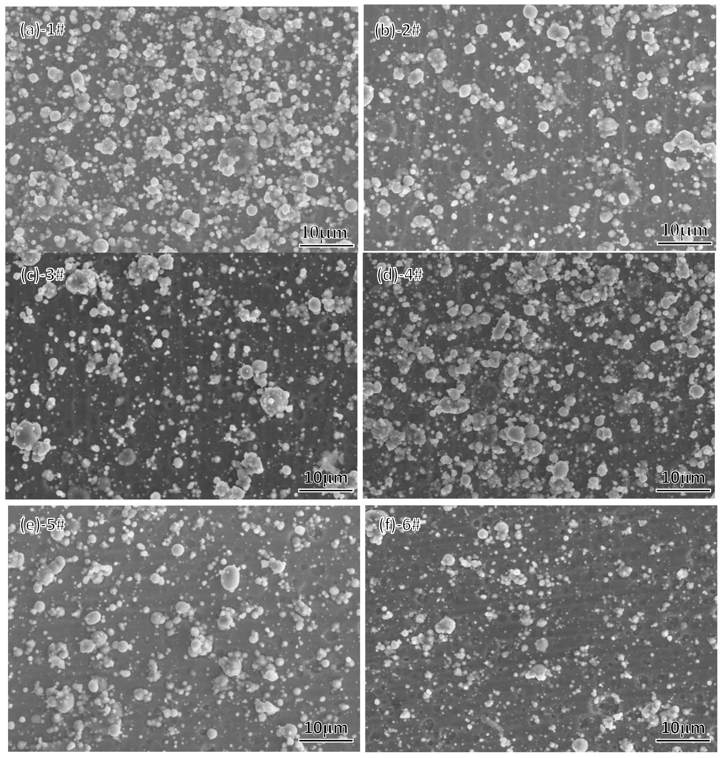
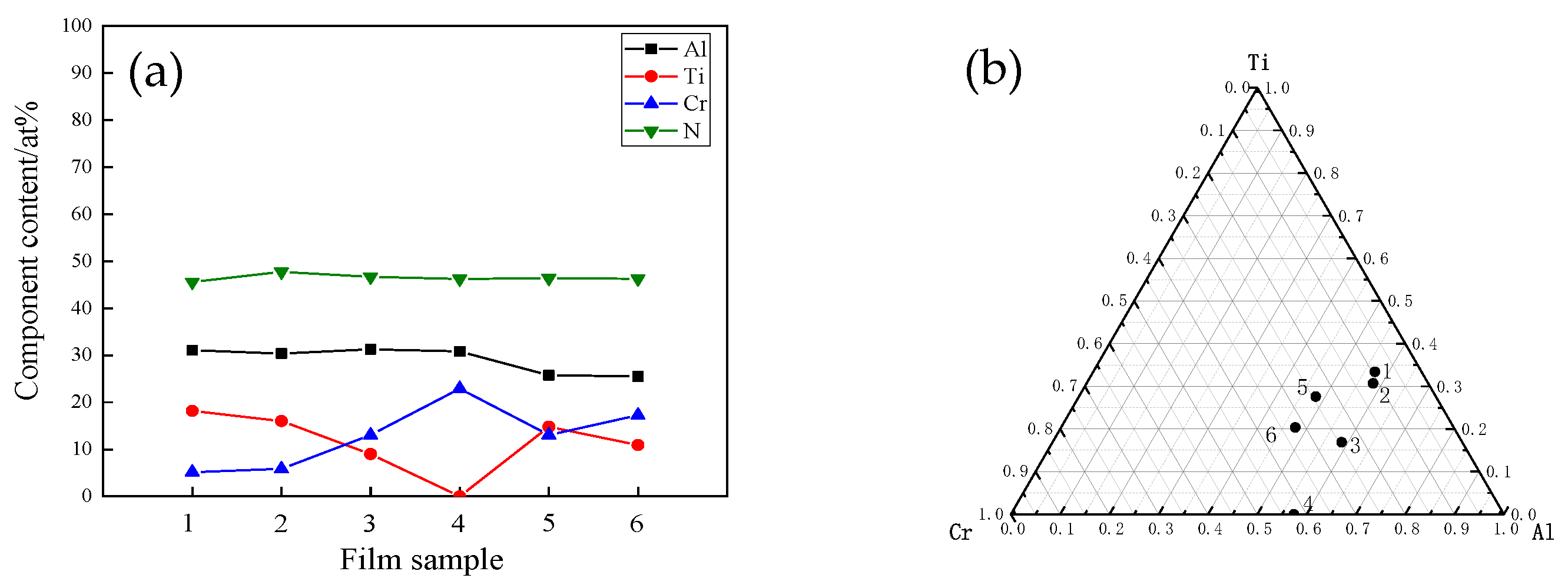
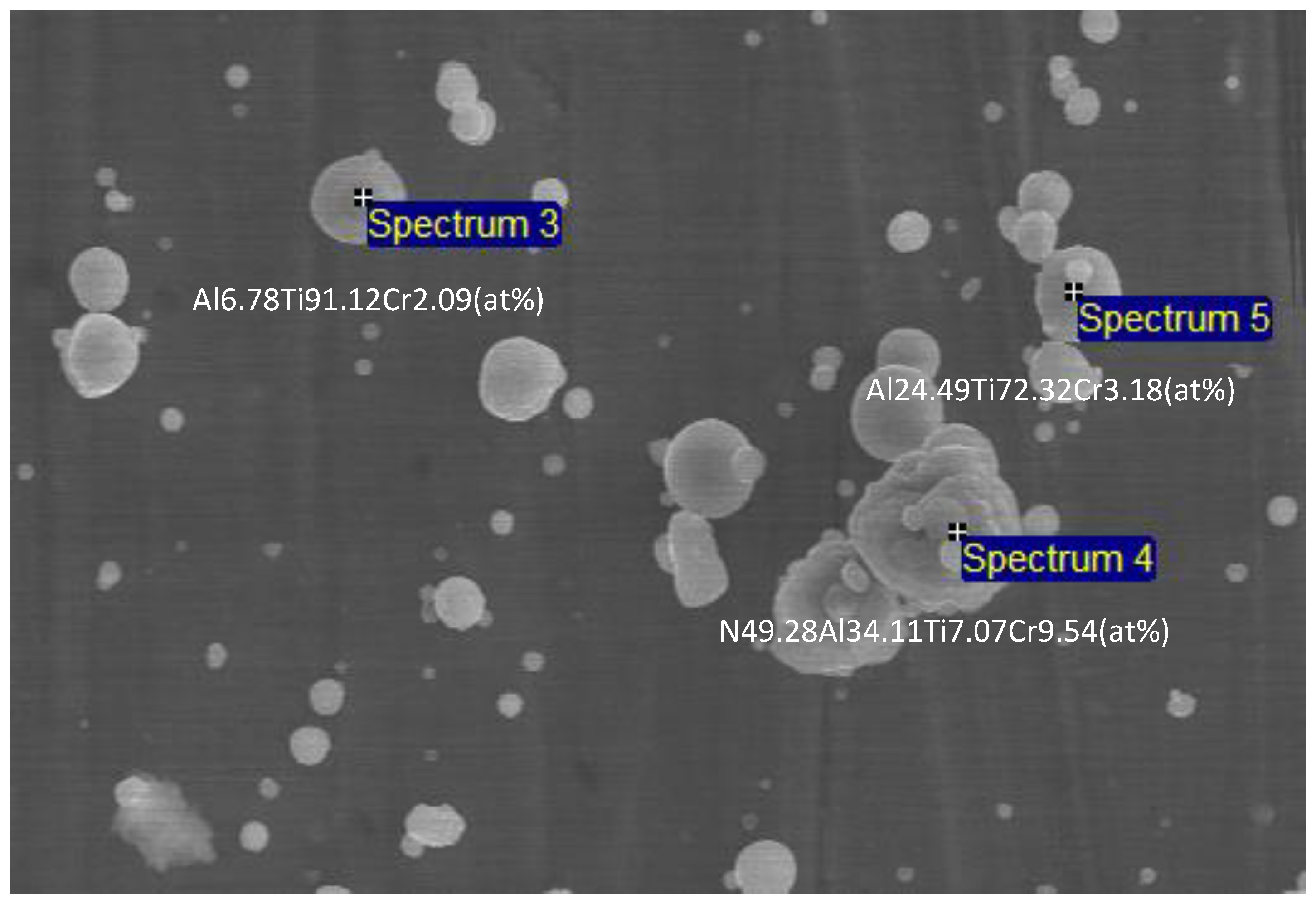
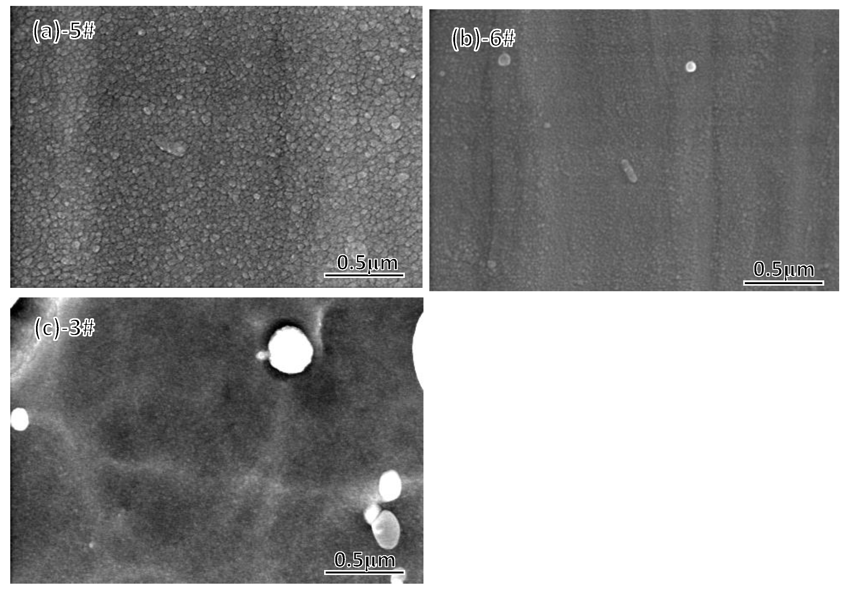
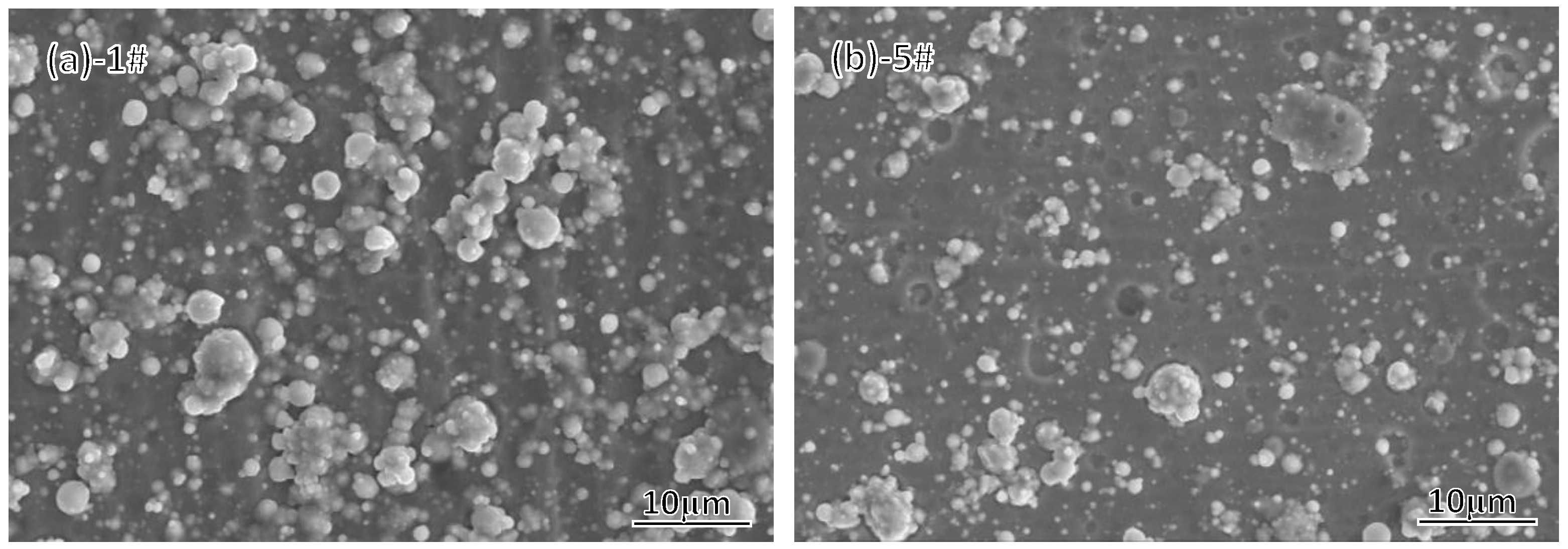
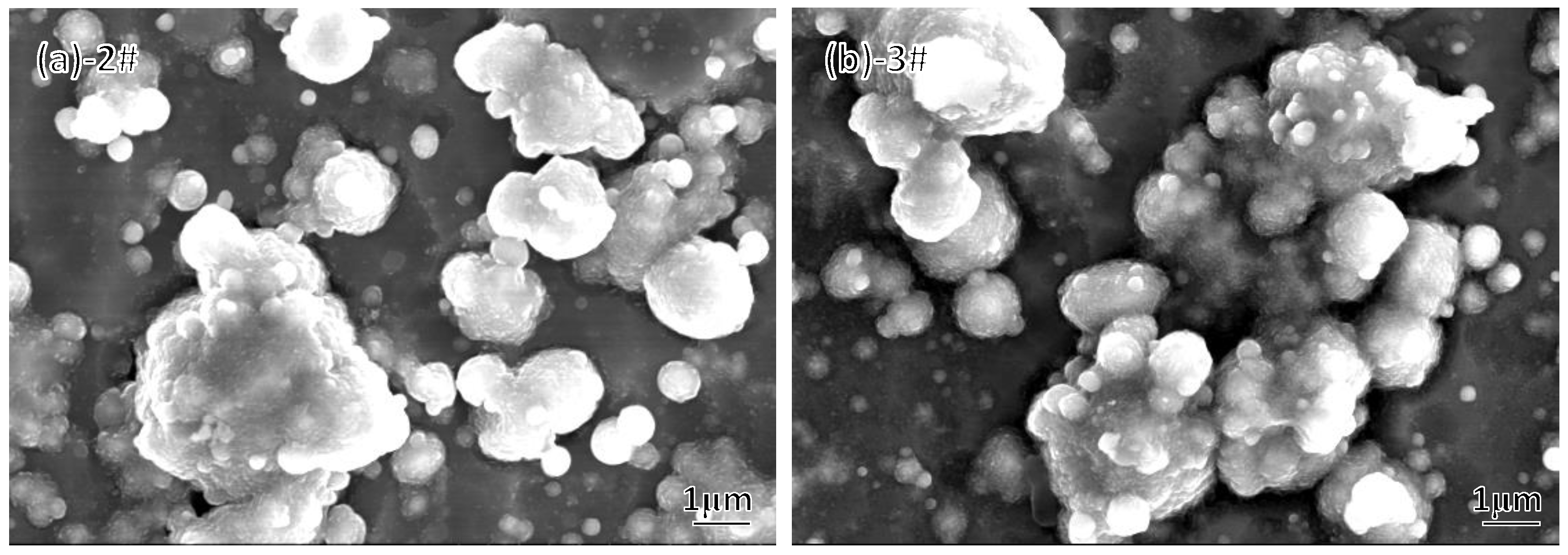
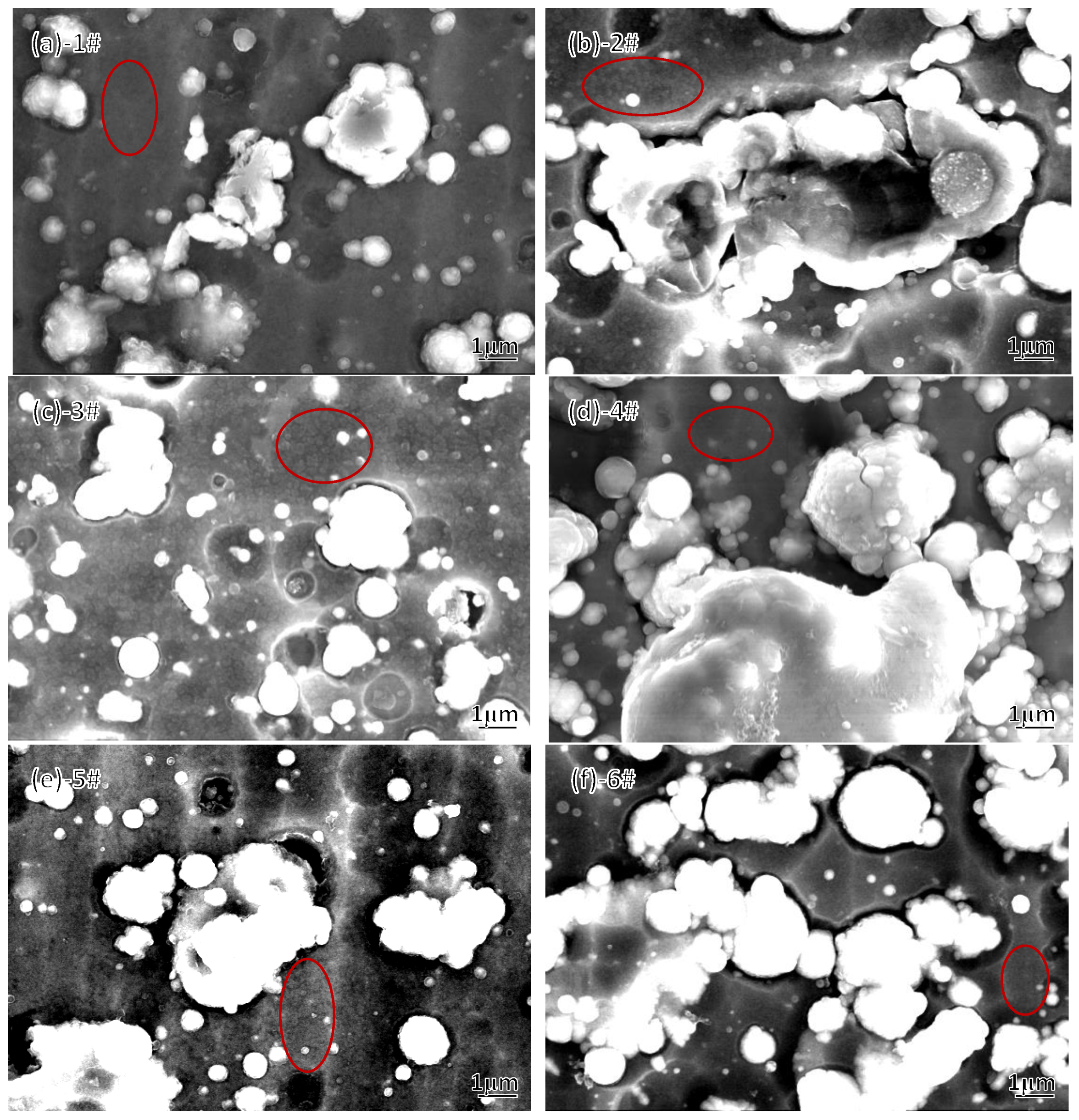
3.1. Surface Morphology and Composition of AlCrTiN Hard Films

The surface morphologies of all the as-deposited films were observed by SEM. The surfaces of all coating layers were very similar and contain distributed “large particles” (liquid droplets). In general, each coating surface consisted of non-liquid and liquid droplets. These particles, with sizes below 6 μm, were formed from the micro-droplets sprayed from the cathode target surface [19,20]. Furthermore, the droplet densities on the surfaces of samples 1# and 4# were higher than those on the surfaces of other specimens, which can be attributed to the higher arc currents and Al contents of the targets used for preparing these two samples. According to the literature, Al-Cr alloy targets are more likely to produce larger particles [21,22]. In addition, some scattered micro-pits were also observed on the film surfaces, owing to the shedding of loosely attached liquid particles during the deposition process (Figure 2).
The surface compositions of the as-deposited films, including the droplet-free areas and large droplet particles, were determined by EDS. Because the N contents in the droplet-free areas of different film samples were nearly identical (46–47 at.%, see Figure 3a), the metal contents in the droplet-free areas could be normalized; then, an intuitive distribution triangle of the metal component contents could be established, as shown in Figure 3b. It was found that film samples 1#, 2#, 3#, and 4# exhibited almost the same Al content (58 at.%) and different Ti/Cr molar ratios, while the Al contents of samples 5# and 6# were equal to 48%. As a result, the AlCrTiN film samples with varied Al contents could be divided into two groups for the subsequent comparative study.
The droplet compositions on the film surfaces had relatively high uncertainties. Sample 3# is used as an example to illustrate this uncertainty. In the same field of view, the composition of droplet particles fluctuated significantly (Figure 4). This can be attributed to the following two reasons. First, it was closely related to the time of droplet attachment to the film surface during deposition. Thus, the droplets that attached at the early stage of the deposition process formed a surface with a composition close to that of the droplet-free areas due to the subsequent deposition of the film layer [23]. However, almost all droplets attached at the later stage of the deposition process were metallic. Second, the compositions of the arc source targets strongly influenced the droplet composition. Because different droplets could overlap on the film surface, this also increased their compositional uncertainty.

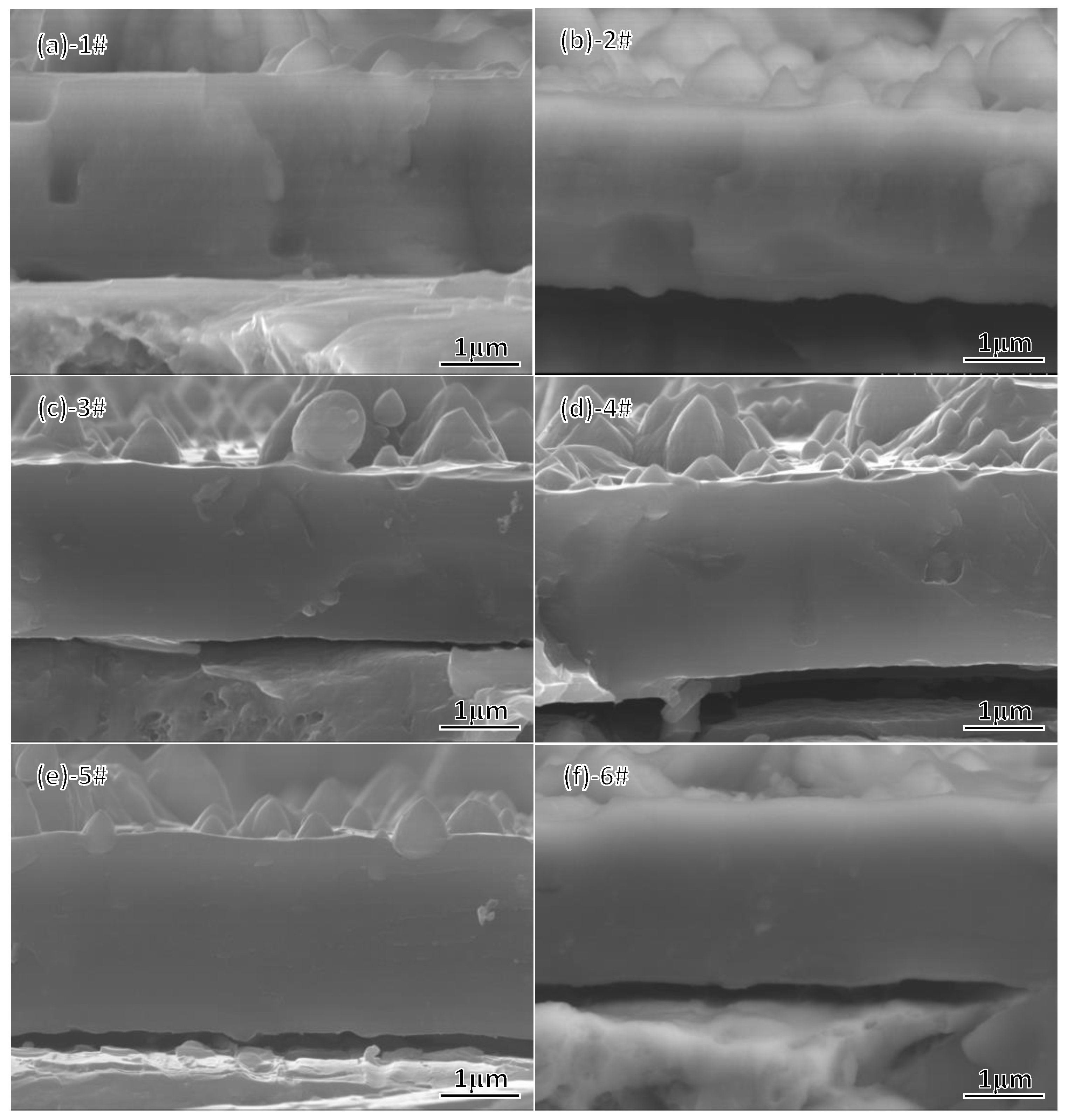
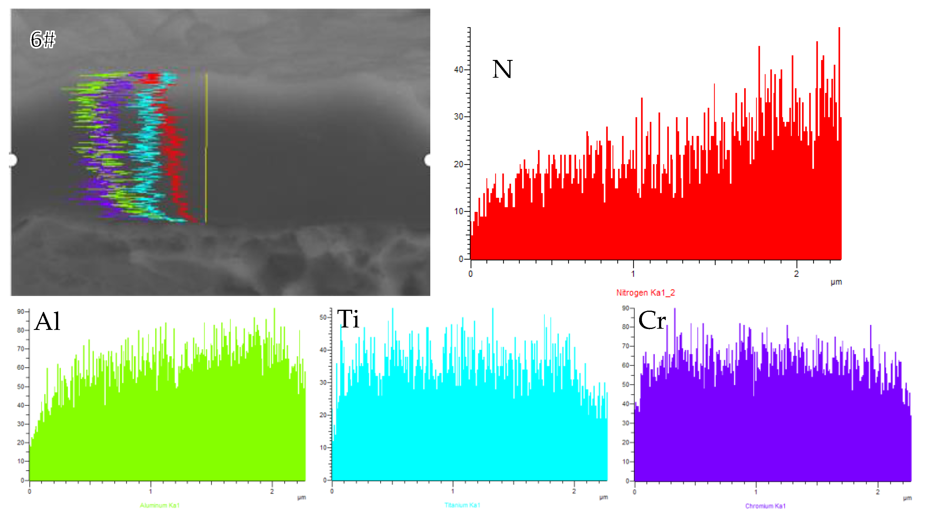
3.2. Cross-Sectional Morphology and Elemental Distribution of AlCrTiN Hard Films

The brittle fracture cross-sectional SEM images of the as-deposited films obtained at room temperature are shown in Figure 5. The thicknesses of the films were very similar (2.1–2.3 μm) and all films exhibited dense and fine columnar crystal morphologies. Figure 6a–c present the grain growth morphology of the film surface in the droplet-free region of samples 5#, 6#, and 3#. Nearly the same fine grain growth morphology was observed in samples 1#–4#, and it was difficult to observe clear crystal grain boundaries. The possible reason is that film samples 1#–4# contained higher Al contents. In comparison, relatively clear grain boundaries were observed in samples 5# and 6#, and the grains of sample 6# were finer than those of sample 5#, with approximately half the grain cross-section size. The grain cross-section sizes of samples 1#–6# were between 30 nm and 60 nm and roughly consistent. The grain size of AlCrN films with an Al/Cr atomic ratio from 1:1 to 2.3:1, deposited by the process parameters similar to those used in the present work, was reported as about 35 nm [24]. The fine columnar crystal microstructure of multi-component nitride hard films deposited by cathodic arc ion plating at a properly high bias is a characteristic of the deposition technology [25,26].
EDS line scanning was performed to determine the elemental distribution in the film growth direction. As expected, the sample coatings demonstrated similar distribution characteristics. The N content in each sample exhibited an apparent gradient in the film growth direction, while the contents of the other metal components remained almost unchanged (Figure 7).
Note that the utilized deposition technology and deposition process parameters produced different effects on the structure and properties of the multi-component nitride hard films. For example, the negative substrate bias affected the structure, composition, phase composition, and hardness of the films [27,28]. Meanwhile, the N2 flow rate and substrate temperature influenced the N content, structure, and hardness of the film layer [29,30]. Although the compositions of the films prepared using different deposition technologies and conditions were either the same or very similar, the properties of these films differed considerably [31,32].
During deposition, the sum of the two arc currents was maintained constant at 110–114 A, and the deposition time was 5 + 10 + 35 min. Meanwhile, the negative bias voltage of the substrate as well as the argon and nitrogen flow rates at the corresponding stages of the deposition process were the same for all film samples. This ensured the nearly identical distributions of N atoms, microstructures, and thicknesses of all films; therefore, the prepared samples mainly differed in their compositions, and their phase compositions were determined by the corresponding film compositions. Finally, the film and phase compositions synergistically influenced the film performance. In summary, film composition was a single important factor affecting film characteristics, which allowed for the examination of the influences of Al content and Ti/Cr molar ratio on the phase composition, hardness, film/substrate bonding strength, and thermal shock properties of the fabricated AlCrTiN hard films.

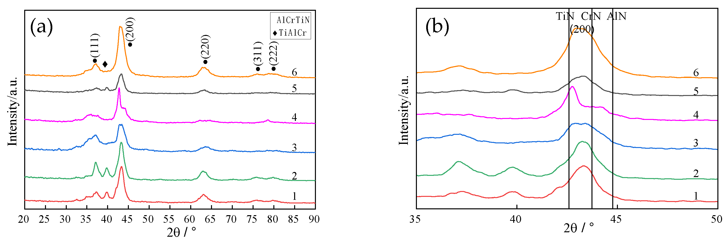
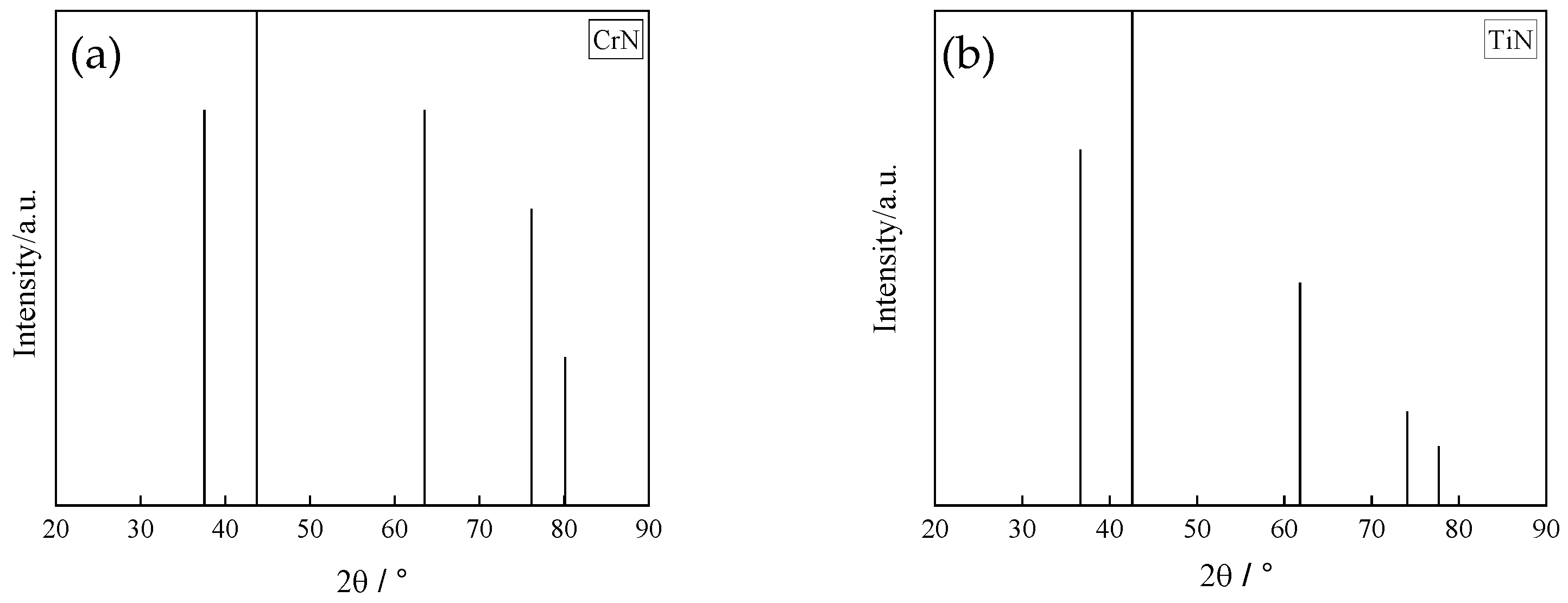
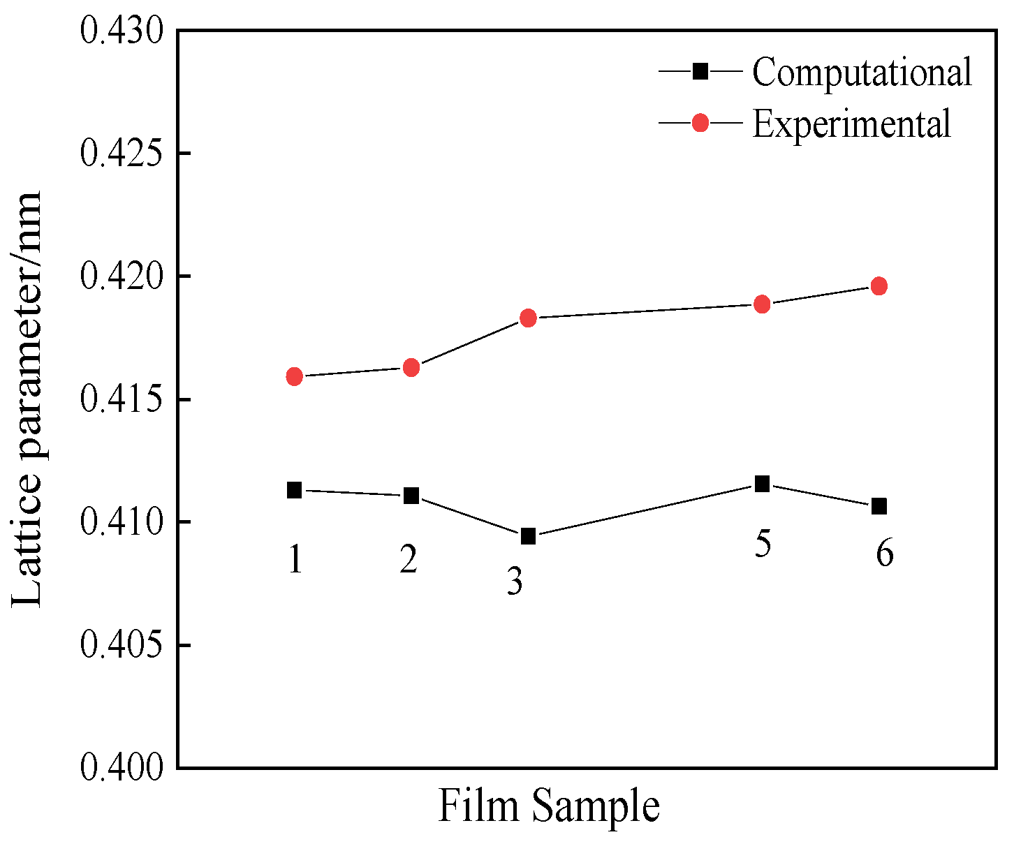
3.3. Phase Compositions of AlCrTiN Hard Films

All films were investigated by small-angle XRD, and the obtained results were analyzed by the JADE software. The XRD patterns depicted in Figure 8a,b exhibit similar characteristics in diffraction peak intensity distribution. According to the standard diffraction patterns of CrN and TiN (Figure 9a,b), the prepared AlCrTiN films are mainly composed of the face-centered cubic (fcc) AlCrTiN phase with substitutional solid solution characteristics and the preferred growth orientation of the (200) crystal plane (tagged with the solid circle symbol, in Figure 8a). Additionally, a TiAlCr alloy phase (tagged with the diamond symbol, in Figure 8a) with varied metal element concentrations, resulting from the droplets attached at the later stage of the deposition process, can be identified. Notably, the fcc AlCrTiN phase present in films 3#, 4#, and 6# exhibits a diffraction peak smoothing or separation feature (Figure 8b) due to the high Al and Cr contents [15,16]. However, unlike the phase transition tendency from fcc structure to hcp structure in Ti1−xAlxN or Cr1−xAlxN films as the Al content among metal components increases up to 60–70 mol.%, the fcc structure rather than hcp structure seems easily retained for AlN in the AlTiCrN films. This may be attributed to the fact that complex lattice distortion due to the addition of Ti atoms into AlCrN lattice weakens the driving force to form hcp structure of AlN phase, as shown by the XRD patterns of films 2# and 5#.
The (200) crystal plane diffraction peak of film sample 4# corresponds to the Al(Cr)N fcc phase with high Al content and Cr(Al)N fcc phase with high Cr content. The Ti contents of samples 3# and 6# are similar, and these samples also exhibit high Al and Cr concentrations, indicating a separation trend. However, their Cr(Al) contents are lower than those of sample 4# because some Cr(Al) atoms are substituted by Ti atoms, which weaken the separation trend. This resulted in the formation of a single AlCrTiN phase broadening the (200) diffraction peak. Therefore, no isolated TiN, CrN, or AlN phases are present in the prepared films except for in sample 4#.
From the results obtained for samples 4#, 3#, 2#, and 1# with the same Al contents, it can be concluded that increasing the Ti/Cr ratio promotes the formation of a single fcc solid solution. The same feature was observed for samples 5# and 6#, suggesting that the AlCrTiN film easily maintains the fcc structure even at high Al contents close to 60%. Although the Al contents in all films (except for sample 4#) are as high as 48%–58%, their diffraction peaks remain between the standard diffraction peaks of the TiN and CrN phases, indicating that the peaks of the (200) crystal plane obtained for these films are shifted to smaller angles.
As shown in Figure 3b, the AlCrTiN film can be seen to be a substitutional solid solution formed by the TiN, CrN, and AlN phases, and their respective proportions are replaced by the normalized proportions of metal element concentrations. The ideal lattice constants of the fcc solid solution of each group of the fabricated film samples were calculated according to Vegard’s law. Additionally, considering the characteristic diffraction peak position of the (200) crystal plane of the AlCrTiN film, the lattice constant of the fcc (AlCrTi)N solid solution phase was directly determined using the JADE software. The obtained results are shown in Figure 10. The experimentally measured lattice constants of all films (except for sample 4#) are significantly higher than the values calculated by Vegard’s law because TiN, CrN, and AlN form a complex fcc solid solution, resulting in large lattice distortions and the formation of vacancy defects. Because the conducted film deposition was a non-equilibrium process, point defects and residual thermal stress were generated in the films, increasing the lattice constant [33].
The texture characteristics of a multi-component nitride film are strongly related to the utilized deposition technology and process parameters. The Cr1−xAlxN film prepared by multi-arc ion plating technology, which is similar to the fabrication method used in the present study, exhibited similar properties (a B1-NaCl-type fcc structure was formed below x = 0.6, and its preferred growth orientations corresponded to the (200) and (111) crystal planes) [34]. However, the AlxCr1−xN film produced by unbalanced magnetron sputtering with two sputtering sources at 0.31 ≤ x ≤ 0.71 had a preferred orientation of the single (111) crystal plane [35].
In this work, the single composition change did not change the phase composition or crystal structure of the AlCrTiN films, owing to the consistency of the deposition process. All films (except for 4#) were composed of the single AlCrTiN substitution fcc solid solution phase and had the same preferred growth orientation corresponding to the (200) crystal plane. Therefore, it can be concluded that the performance difference of these films originated from composition changes. This effect mainly involved solution strengthening caused by lattice distortion.

3.4. Hardness and Adhesion of AlCrTiN Hard Films

The microhardness test data obtained for all film layers of droplet-free areas are listed in Table 2. It shows that the hardness values of AlCrTiN samples 1#–4# with equal molar ratios of AlN (~58%) are lower than those of the AlCrN and AlTiN films with the same AlN molar ratio [16,35]. These results indicate that the hardness of the AlCrTiN films formed by adding Ti or Cr atoms to AlCrN or AlTiN films with high Al contents is relatively low. However, with a decrease in the molar ratio of AlN to 48%, the hardness values of the AlCrTiN films 5# and 6# increase as compared with those of films 2# and 3#.
Under the premise of maintaining the fcc structure of a ternary substitutional solid solution nitride film (such as AlCrN, TiAlN, and TiCrN), as the content of the second metal component increases, the lattice distortion will increase, and then the hardness of the film layer tends to increase [3,34,36]. The hardness maximum value is reached when the metal component ratio is close to 1:1.
The present AlTiCrN substitutional solid solution films were formed by adding Ti atoms to AlCrN fcc structure and replacing some of the Al and Cr atoms because the ratio of N/Metal is the same and almost equal to 1:1. In this case, three solid solution combinations were produced: a combination of AlN and TiN, a combination of AlN and CrN (both of which have high AlN fractions), and a combination of TiN and CrN. Therefore, the hardness of the AlTiCrN solid solution film was reduced because the AlCrN and AlTiN films with high Al contents exhibited low hardness values. Only when the addition of Ti atoms reached a certain fraction among the metal components and the AlTiCrN solid solution was gradually transformed into a combination of AlN/TiN and AlN/CrN, both with a small concentration difference, did the film hardness increase, as shown by films 5# and 6#.
According to previous studies, the hardness of the Cr0.66Al0.34N ternary film is 28.5 GPa. With the addition of the Ti component at fTi = 5% and 10%, the hardness values of the resulting Cr65Ti5Al30N and Cr61Ti10Al29N films increase to 34 and 40 GPa, respectively. When fTi is further increased, the hardness begins to decrease slowly. When the Ti content reaches 64%, the hardness of the Cr26Ti64Al10N film decreases to 29 GPa [37]. However, the hardness of the Ti0.17Al0.53Cr0.30N, Ti0.23Al0.36Cr0.4N, and Ti0.46Al0.20Cr0.34N films prepared using different combinations of the TiAl, Cr, and Al targets monotonically increases with a decrease in the Al content and increase in the Ti content [17]. The work to investigate the effect of bias on the composition and hardness of TiAlCrN films shows that as the bias increases from 100 V, 150 V, 200 V to 250 V, the composition of the films is successively changed into Ti23Al18Cr20N, Ti27Al16Cr21N, Ti20Al14Cr29N, Ti23Al12Cr31N, and the hardness is successively changed into HV2800, HV5100, HV4650, HV4650V [38]. Thus, it can be concluded that the hardness values of the TiN-based TiAlCrN and CrN-based CrTiAlN films are generally higher than that of the AlN-based AlTiCrN film.
In addition, the N/metal ratio of nitride hard films directly affects their hardness, which decreases when this ratio deviates significantly from the stoichiometric ratio of 1:1 [39,40]. Therefore, the N content in the hardening film layer is generally maintained between 45 and 52 at.%, which is close to the ideal chemical ratio required to maximize the hardness of the nitride film. The N contents in the hardening surface layers of the as-deposited AlTiCrN solid solution films prepared in this study amounted to 47%–48%, which ensured their maximum hardness at various ratios of the metal components.
The film/substate adhesive strength values of the AlCrTiN hard films (Table 2) suggest that the adhesion between the film and substrate is relatively strong, except for film samples 1# and 4# (the other films layers withstood critical loads exceeding 200 N). Previous studies have shown that designing the N gradient distribution in nitride hard films is an effective method for improving the film/substrate adhesion performance [41,42]. For example, the adhesive strength of a (TiAlNb)N film with N gradient distribution prepared was much larger than that of a (TiAlNb)N film without an alloy transition layer and N gradient distribution [11,43].
In the present study, the ion bombardment of the high-speed steel substrate prior to film deposition and subsequent deposition of the alloy transition layer prevented the separation of the film from the substrate and increased the film adhesive strength. Optimizing the gradient distribution of the N element in the film growth direction inhibits the accumulation of growth stress and produces a gradient of the thermal expansion coefficient, which helps improve both the adhesion [41,42] and thermal shock performance of the film.

3.5. Thermal Shock Cycling Performance of AlCrTiN Hard Films

The cutting tools and dies coated with nitride hard films are generally required to have long service lives and good machining properties under hot and cold cycling conditions. Therefore, the corresponding hard films must possess high thermal shock resistances.
The fabricated AlCrTiN hard films were subjected to thermal shock cycles at 600 °C, and the changes in the surface morphology were observed after each cycle. After eight cycles, no significant changes in the film surfaces were detected by SEM with a 2000× magnification. The surface changes of two samples, 1# with more droplets and 5# with fewer droplets, are given as examples, as shown in Figure 11. To observe the film surface more carefully, the magnification was increased to 10,000×. During the entire eight thermal shock cycles, the observable change in the surface morphology was that the surface of droplet particles became coarse, and some very small particles appeared. In contrast, negligible morphological changes occurred in the droplet-free areas. This indicates that the surface oxidation rate of the droplets was significantly higher than that of the droplet-free area. After the eighth cycle, neither cracking or shedding of droplets nor cracks on the surface of the droplet-free area were detected in any of the samples. Figure 12a,b show the surface changes of samples 2# and 3#, respectively.
After the 16th cycle, inconsistent changes were observed on the film surfaces with different compositions (Figure 13). For films 1# and 4#, no obvious changes in the film surface morphologies (the droplet-free areas) were observed, as shown by the red circle in Figure 13a,d. However, a few of cracks formed on the surfaces of droplet particles. For films 2# and 3#, the obvious growth of the cross-section grain size of the film layer (the droplet-free areas) was observed up to about 200 nm and 300 nm, respectively, as shown by the red circle in Figure 13b,c. Meanwhile, a few cracks were observed on droplet particles. For films 5# and 6#, on the film surface of the droplet-free areas, the grain boundaries became blurred and the cross-section size of grain in film 5# seemed to be larger than that in film 6#, as shown by the red circle in Figure 13e,f. Additionally, no visible cracks formed on the surfaces of droplet particles. In general, all films exhibited no cracks in the droplet-free area through 16 thermal shock cycles. This means that the prepared film samples possessed high thermal shock resistances.
The Al element has a relatively high oxidation resistance because it easily forms a dense oxide (Al2O3) layer that covers the film surface during thermal shock, thus preventing oxygen atoms from further penetrating the film and resulting in the oxidation of the film layer [44]. However, the Cr element can promote the oxidation of Al atoms and accelerate the formation of Al2O3 [45]. Therefore, a film with high Al content typically exhibits high thermal shock resistance. In the present study, all film layers of the droplet-free areas with high Al and Cr contents demonstrated high thermal shock resistance. Because the thermal shock cycling temperature was 600 °C, which is lower than the preferred oxidation temperature of Al [46,47,48], films 1#–4# with higher Al contents, in comparison with films 5# and 6#, did not exhibit obvious advantages in terms of thermal shock resistance.

4. Conclusions

In this study, two sets of AlCrTiN hard films with different Al contents among metal components were prepared. All of the films exhibited almost identical surface morphologies, cross-sectional microstructures and morphologies, thicknesses, and N content distributions because the combination of alloy targets and parameters of the deposition process were adjusted for each sample. The main conclusions from the obtained results are summarized below.
  • All AlTiCrN hard films (i.e., droplet-free areas, the same below) consist of the fcc solid solutions with a columnar fine microstructure and the preferred growth orientation of (200) crystal plane at high Al contents from 48 up to 58 at.%. AlCrTiN films easily maintains the fcc structure even at high Al contents up to 58 at.% due to the complex lattice distortion.
  • The hardness of AlTiCrN films with an Al content of 58 at.% is significantly lower than those of TiCrAlN and CrTiAlN hard films with high Ti and Cr contents, and varying the Ti/Cr ratio does not increase hardness of the AlTiCrN films.
  • The hardness of AlCrTiN films can be improved up to HV2850 by properly reducing the Al content from 58 at.% to 48 at.%. Meanwhile, the film/substrate adhesion performance is strong enough in terms of critical loads greater than 200 N.
  • AlCrTiN films maintain high thermal shock resistance at 600 °C even when the Al content decreases from 58 at.% to 48 at.%. In the droplet-free area of the film surface, no crack appeared through 16 thermal shock cycles. The thermal shock failure of the films is typically manifested as a rupture and droplet particles falling off.
  • The optimal composition of AlCrTiN hard films is 25:13:15:47 (at.%), which is determined from the results of hardness, adhesion, and thermal shock cycling resistance measurements. This optimal AlCrTiN hard film can be used as an option for protective coatings of hot-pressure die tools.

Author Contributions

Conceptualization, methodology, J.Z.; investigation, L.P.; resources, X.W.; data curation, writing—original draft preparation, L.P.; writing—review and editing, X.W.; funding acquisition, X.W. All authors have read and agreed to the published version of the manuscript.

Funding

This research was funded by Liaoning Province Doctor Start-up Fund, grant number 2021-BS-276.

Institutional Review Board Statement

Not applicable.

Informed Consent Statement

Not applicable.

Data Availability Statement

Not applicable.

Conflicts of Interest

The authors declare no conflict of interest.

References

  1. Hörling, A.; Hultman, L.; Odén, M.; Sjölén, J.; Karlsson, L. Mechanical properties and machining performance of Ti1−xAlxN-coated cutting tools. Surf. Coat. Technol. 2004, 191, 384–392. [Google Scholar] [CrossRef]
  2. Lamni, R.; Sanjinés, R.; Parlinska-Wojtan, M.; Karimi, A.; Lévy, F. Microstructure and nanohardness properties of Zr-Al-N and Zr-Cr-N thin films. J. Vac. Sci. Technol. A 2005, 23, 593–598. [Google Scholar] [CrossRef]
  3. Niu, E.W.; Li, L.; Lv, G.H.; Chen, H.; Li, X.Z.; Yang, X.Z.; Yang, S.Z. Characterization of Ti-Zr-N films deposited by cathodic vacuum arc with different substrate bias. Appl. Surf. Sci. 2008, 254, 3909–3914. [Google Scholar] [CrossRef]
  4. Falub, C.V.; Karimi, A.; Ante, M.; Kalss, W. Interdependence between stress and texture in arc evaporated Ti-Al-N thin films. Surf. Coat. Technol. 2007, 201, 5891–5898. [Google Scholar] [CrossRef]
  5. Kimura, A.; Hasegawa, H.; Yamada, K.; Suzuki, T. Metastable Ti1−xAlxN films with different Al content. J. Mater. Sci. Lett. 2000, 19, 601–602. [Google Scholar] [CrossRef]
  6. Donohue, L.A.; Cawley, J.; Brooks, J.S.; Münz, W.D. Deposition and characterization of TiAlZrN films produced by a combined steered arc and unbalanced magnetron sputtering technique. Surf. Coat. Technol. 1995, 74, 123–134. [Google Scholar] [CrossRef]
  7. Zhang, J.; Guo, W.; Zhang, Y.; Guo, Q.; Wang, C.; Zhang, L. Mechanical properties and phase structure of (TiAlZr)N films deposited by multi arc ion plating. Thin Solid Film. 2009, 517, 4830–4834. [Google Scholar] [CrossRef]
  8. Yamamoto, K.; Sato, T.; Takahara, K.; Hanaguri, K. Properties of (Ti,Cr,Al)N coatings with high Al content deposited by new plasma enhanced arc-cathode. Surf. Coat. Technol. 2003, 174, 620–626. [Google Scholar] [CrossRef]
  9. Santana, A.E.; Karimi, A.; Derflinger, V.H.; Schütze, A. Microstructure and mechanical behavior of TiAlCrN multilayer thin films. Surf. Coat. Technol. 2003, 177, 334–340. [Google Scholar] [CrossRef]
  10. Hsu, C.H.; Chen, K.L.; Lin, Z.H.; Su, C.Y.; Lin, C.K. Bias effects on the tribological behavior of cathodic arc evaporated CrTiAlN coatings on AISI 304 stainless steel. Thin Solid Film. 2010, 518, 3825–3829. [Google Scholar] [CrossRef]
  11. Zhang, J.; Yin, L.Y. Microstructure and mechanical properties of (Ti,Al,Nb)N hard films with N-gradient distributions. Thin Solid Film. 2015, 584, 141–145. [Google Scholar] [CrossRef]
  12. PalDey, S.; Deevi, S.C. Single layer and multilayer wear resistant coatings of (Ti,Al)N: A review. Mater. Sci. Eng. A 2003, 342, 58–79. [Google Scholar] [CrossRef]
  13. Greczynski, G.; Hultman, L.; Odén, M. X-ray photoelectron spectroscopy studies of Ti1−xAlxN (0≤x≤0.83) high temperature oxidation: The crucial role of Al concentration. Surf. Coat. Technol. 2019, 374, 923–934. [Google Scholar] [CrossRef]
  14. Pemmasani, S.P.; Valleti, K.; Gundakaram, R.C.; Rajulapati, K.V.; Mantripragada, R.; Koppoju, S.; Joshi, S.V. Effect of microstructure and phase constitution on mechanical properties of Ti1−xAlxN coatings. Appl. Surf. Sci. 2014, 313, 936–946. [Google Scholar] [CrossRef]
  15. Wang, D.; Lin, S.S.; Liu, L.Y.; Xue, Y.N.; Yang, H.Z.; Jiang, B.L.; Zhou, K.S. Effect of Bias Voltage on Microstructure and Erosion Resistance of CrAlN Coatings Deposited by Arc Ion Plating. Rare Met. Mater. Eng. 2020, 49, 2583–2590. [Google Scholar]
  16. Hasegawa, H.; Suzuki, T. Effects of second metal contents on microstructure and micro-hardness of ternary nitride films synthesized by cathodic arc method. Surf. Coat. Technol. 2004, 188–189, 234–240. [Google Scholar] [CrossRef]
  17. Vattanaprateep, N.; Panich, N.; Surinphong, S.; Tungasmita, S.; Wangyao, P. Structural and Mechanical Properties of Nanostructured TiAlCrN Thin Films Deposited by Cathodic Arc Deposition. High Temp. Mater. Proc. 2013, 32, 107–111. [Google Scholar] [CrossRef]
  18. Zhang, J.; Peng, L.; Wang, X.; Liu, D.; Wang, N. Effects of Zr/(Zr+Ti) Molar Ratio on the Phase Structure and Hardness of TixZr1−xN Films. Coatings 2021, 11, 1342. [Google Scholar] [CrossRef]
  19. Harris, S.G.; Doyle, E.D.; Wong, Y.C.; Munroe, P.R.; Cairney, J.M.; Long, J.M. Reducing the macroparticle content of cathodic arc evaporated TiN coatings. Surf. Coat. Technol. 2003, 183, 283–294. [Google Scholar] [CrossRef]
  20. Shiao, M.H.; Shieu, F.S. Formation of macroparticles in arc ion-plated nitride coatings. J. Vac. Sci. Technol. A Vac. Surf. Film. 2001, 19, 703–705. [Google Scholar] [CrossRef]
  21. Wan, X.S.; Zhao, S.S.; Yang, Y.; Gong, J.; Sun, C. Effects of nitrogen pressure and pulse bias voltage on the properties of Cr-N coatings deposited by arc ion plating. Surf. Coat. Technol. 2009, 204, 1800–1810. [Google Scholar] [CrossRef]
  22. Vyskoceil, J.; Musil, J. Cathodic arc evaporation in thin film technology. Vac. Sci. Technol. 1992, A10, 1740–1748. [Google Scholar] [CrossRef]
  23. Shiao, M.H.; Shieu, F.S. A formation mechanism for the macroparticles in arc ion-plated TiN films. Thin Solid Films 2001, 386, 27–31. [Google Scholar] [CrossRef]
  24. Tritremmel, C.; Daniel, R.; Lechthaler, M.; Polcik, P.; Mitterer, C. Influence of Al and Si content on structure and mechanical properties of arc evaporated Al-Cr-Si-N thin films. Thin Solid Film. 2013, 534, 403–409. [Google Scholar] [CrossRef]
  25. Kuczyk, M.; Krülle, T.; Zawischa, M.; Kaspar, J.; Zimmer, O.; Leonhardt, M.; Leyens, C.; Zimmermann, M. Microstructure and mechanical properties of high entropy alloy nitride coatings deposited via direct current cathodic vacuum arc deposition. Surf. Coat. Technol. 2022, 448, 128916–128930. [Google Scholar] [CrossRef]
  26. Chen, W.L.; Zheng, J.; Lin, Y.; Kwon, S.; Zhang, S.L. Comparison of AlCrN and AlCrTiSiN coatings deposited on the surface of plasma nitrocarburized high carbon steels. Appl. Surf. Sci. 2015, 332, 525–532. [Google Scholar] [CrossRef]
  27. Cai, F.; Chen, M.; Li, M.; Zhang, S. Influence of negative bias voltage on microstructure and property of Al-Ti-N films deposited by multi-arc ion plating. Ceram. Int. 2017, 43, 3774–3783. [Google Scholar] [CrossRef] [Green Version]
  28. Liu, W.; Li, A.; Wu, H.; He, R.; Huang, J.; Long, Y.; Deng, X.; Wang, Q.; Wang, C.; Wu, S. Effects of bias voltage on microstructure, mechanical properties, and wear mechanism of novel quaternary (Ti, Al, Zr)N coating on the surface of silicon nitride ceramic cutting tool. Ceram. Int. 2016, 42, 17693–17697. [Google Scholar] [CrossRef]
  29. Tang, J.F.; Lin, C.Y.; Yang, F.C.; Chang, C.L. Influence of Nitrogen Content and Bias Voltage on Residual Stress and the Tribological and Mechanical Properties of CrAlN Films. Coatings 2020, 10, 546. [Google Scholar] [CrossRef]
  30. Larijani, M.M.; Tabrizi, N.; Norouzian, S.; Jafari, A.; Lahouti, S.; Hosseini, H.H.; Afshari, N. Structural and mechanical properties of ZrN films prepared by ion beam sputtering with varying N2/Ar ratio and substrate temperature. Vacuum 2006, 81, 550–555. [Google Scholar] [CrossRef]
  31. Donohue, L.A.; Cawley, J.; Brooks, J.S. Deposition and characterisation of arc-bond sputter TixZryN coatings from pure metallic and segmented targets. Surf. Coat. Technol. 1995, 72, 128–138. [Google Scholar] [CrossRef]
  32. Le Bourhis, E.; Goudeau, P.; Staia, M.H.; Carrasquero, E.; Puchi-Cabrera, E.S. Mechanical properties of hard AlCrN-based coated substrates. Surf. Coat. Technol. 2009, 203, 2961–2968. [Google Scholar] [CrossRef]
  33. Elstner, F.; Gautier, C.; Moussaoui, H.; Piot, O.; Machet, J. A comparative study of structure and residual stress in chromium nitride films deposited by vacuum arc evaporation, ion plating, and DC magnetron sputtering. Phys. Stat. Sol. 2010, 158, 505–521. [Google Scholar] [CrossRef]
  34. Hasegawa, H.; Kawate, M.; Suzuki, T. Effects of Al contents on microstructures of Cr1−xAlxN and Zr1−xAlxN films synthesized by cathodic arc method. Surf. Coat. Technol. 2005, 200, 2409–2413. [Google Scholar] [CrossRef]
  35. Kim, G.S.; Lee, S.Y. Microstructure and mechanical properties of AlCrN films deposited by CFUBMS. Surf. Coat. Technol. 2006, 201, 4361–4366. [Google Scholar] [CrossRef]
  36. Boxman, R.L.; Zhitomirsky, V.N.; Grimberg, I.; Rapoport, L.; Goldsmith, S.; Weiss, B.Z. Structure and hardness of vacuum arc deposited multi-component nitride coatings of Ti, Zr and Nb. Surf. Coat. Technol. 2000, 125, 257–262. [Google Scholar] [CrossRef]
  37. Lin, J.; Zhang, X.; Ou, Y.; Wei, R. The structure, oxidation resistance, mechanical and tribological properties of CrTiAlN coatings. Surf. Coat. Technol. 2015, 277, 58–66. [Google Scholar] [CrossRef]
  38. Zhang, J.; Lv, H.; Cui, G.; Jing, Z.; Wang, C. Effects of bias voltage on the microstructure and mechanical properties of (Ti,Al,Cr)N hard films with N-gradient distributions. Thin Solid Film. 2011, 519, 4818–4823. [Google Scholar] [CrossRef]
  39. Tay, B.K.; Shi, X.; Yang, H.S.; Tan, H.S.; Chua, D.; Teo, S.Y. The effect of deposition conditions on the properties of TiN thin films prepared by filtered cathodic vacuum-arc technique. Surf. Coat. Technol. 1999, 111, 229–233. [Google Scholar] [CrossRef]
  40. Sundgren, J.-E. Structure and propertiesof TiN coatings. Thin Solid Film. 1985, 128, 21–44. [Google Scholar] [CrossRef]
  41. Chen, L.; Wang, S.Q.; Du, Y.; Li, J. Microstructure and mechanical properties of gradient Ti(C,N) and TiN/Ti(C,N) multilayer PVD coatings. Mater. Sci. Eng. A. 2007, 478, 336–339. [Google Scholar] [CrossRef]
  42. Dobrzański, L.A.; Żukowska, L.W.; Mikuła, J.; Gołombek, K.; Pakuła, D.; Pancielejko, M. Structure and mechanical properties of gradient PVD coatings. J. Mater. Process.Technol. 2008, 201, 310–314. [Google Scholar] [CrossRef]
  43. Yin, L.Y.; Zhang, J. Microstructure and mechanical properties of (TiAlNb)N films. Adv. Mater. Res. 2014, 812, 915–916. [Google Scholar] [CrossRef]
  44. Polcar, T.; Cavaleiro, A. High-temperature tribological properties of CrAlN, CrAlSiN and AlCrSiN coatings. Surf. Coat. Technol. 2011, 206, 1244–1251. [Google Scholar] [CrossRef]
  45. Kawate, M.; Hashimoto, A.K.; Suzuki, T. Oxidation Resistance of CrAlN and TiAlN Films. Surf. Coat. Technol. 2003, 165, 163–167. [Google Scholar] [CrossRef]
  46. Endrino, J.L.; Fox-Rabinovich, G.S.; Gey, C. Hard AlTiN, AlCrN PVD Coatings for Machining of Austenitic Stainless Steel. Surf. Coat. Technol 2006, 200, 6840–6845. [Google Scholar] [CrossRef]
  47. Fox-Rabinovich, G.S.; Beake, B.D.; Endrino, J.L.; Veldhuis, S.C.; Parkinson, R.; Shuster, L.S.; Migranov, M.S. Effect of Mechanical Properties Measured at Room and Elevated Temperatures on the Wear Resistance of Cutting Tools with TiAlN and AlCrN Coatings. Surf. Coat. Technol. 2006, 200, 5738–5742. [Google Scholar] [CrossRef]
  48. Jäger, N.; Meindlhumer, M.; Zitek, M.; Spor, S.; Hruby, H.; Nahif, F.; Julin, J.; Rosenthal, M.; Keckes, J.; Mitterer, C.; et al. Impact of Si on the high-temperature oxidation of AlCr(Si)N coatings. J. Mater. Sci. Technol. 2022, 100, 91–100. [Google Scholar] [CrossRef]
Figure 1. The flow rates of Ar and N2 vs. deposition time. Black line: Ar, and red line: N2.
Coatings 13 00547 g001
Figure 2. Surface morphologies of the deposited AlCrTiN films. The numbers (af) correspond to samples 1#–6#, respectively.
Coatings 13 00547 g002
Figure 3. Chemical composition of the surface of the films. (a) Droplet-free film layer areas. (b) The corresponding normalized metal component contents.
Coatings 13 00547 g003
Figure 4. Chemical composition of the droplets on the surface of films.
Coatings 13 00547 g004
Figure 5. Cross-sectional morphologies of the films. The numbers (af) correspond to samples 1#–6#, respectively.
Coatings 13 00547 g005
Figure 6. The grain growth morphology of the film surface in the non-droplet region; (ac) correspond to samples 5#, 6#, and 3#, respectively.
Coatings 13 00547 g006
Figure 7. Cross-sectional elemental distribution in the growth direction of the films (sample 6#).
Coatings 13 00547 g007
Figure 8. (a) XRD patterns of AlCrTiN films, (b) Partial enlarged detail of the XRD patterns.
Coatings 13 00547 g008
Figure 9. Standard XRD patterns of CrN and TiN. (a) CrN. (b) TiN.
Coatings 13 00547 g009
Figure 10. Lattice constant of the films obtained from the experiments and calculations using Vegard’s law. Notes: 1. excluding film 4#; 2. the 2θ angle of (200) crystal plane of films 3# and 6# is an estimated value.
Coatings 13 00547 g010
Figure 11. Surface morphologies of AlTiCrN hard films after the 8th thermal shock cycle. (a) Sample 1#. (b) Sample 5#.
Coatings 13 00547 g011
Figure 12. Surface morphologies of film samples 2# and 3# after 8th thermal shock cycle. (a) Sample 2#. (b) Sample 3#.
Coatings 13 00547 g012
Figure 13. Surface morphologies of film samples after 16 thermal shock cycles. The numbers (af) correspond to sample numbers 1#–6#, respectively. Red circle region: droplet-free area.
Coatings 13 00547 g013
Table 1. Cathodic arc current combination during the deposition of AlTiCrN films (total current = 110–114 A).
Sample No.Cathodic Arc Current (A)Deposition Time (min)Bias (V)
1Al70Cr30Al70Ti305 + 10 + 35180
5654
2Al70Cr30Al50Ti505 + 10 + 35180
5855
3Al50Cr50Al64Ti365 + 10 + 35180
5955
4Al70Cr30Al50Cr505 + 10 + 35180
5060
5Al50Cr50Al64Ti365 + 10 + 35180
5555
6Al50Cr50Al64Ti365 + 10 + 35180
5852
Table 2. The microhardness of AlCrTiN films.
Sample No.AlN/mol %TiN/mol %CrN/mol %TiN/CrNMicrohardness (HV)Adhesion (N)
157.1433.399.443.542680 ± 200>150
258.1430.6711.22.742650 ± 200>200
358.6716.8824.470.692620 ± 200>200
457.40042.602750 ± 200>130
548.0627.624.361.132850 ± 200>200
647.5420.3332.130.632730 ± 200>200
Disclaimer/Publisher’s Note: The statements, opinions and data contained in all publications are solely those of the individual author(s) and contributor(s) and not of MDPI and/or the editor(s). MDPI and/or the editor(s) disclaim responsibility for any injury to people or property resulting from any ideas, methods, instructions or products referred to in the content.

