Article

The Leakage Current Characteristics of High-Gradient MOA Plate and Its Heating Analysis with Coatings under High-Frequency Overvoltage

1
Institute of Electrical Engineering, Beijing Jiaotong University, Haidian District, Beijing 100044, China
2
Shuohuang Railway Development Co., Ltd. of National Energy, Cangzhou 062350, China
3
National Energy Transportation Technology Research Institute Co., Ltd., Beijing 100080, China
*
Author to whom correspondence should be addressed.
Coatings 2023, 13(3), 497; https://doi.org/10.3390/coatings13030497
Submission received: 31 January 2023 / Revised: 20 February 2023 / Accepted: 22 February 2023 / Published: 24 February 2023
(This article belongs to the Special Issue Advances in Dielectric Coatings)

Abstract

:
High-frequency overvoltage generated in railways results in explosions of Electric Multiple Units’ (EMUs) arrestors. To solve this problem, the leakage current characteristics and heat transfer process of high-gradient MOA plates under high-frequency overvoltage has been studied. The leakage current characteristics of arrestor plates under high-frequency voltage was obtained and the element distribution has been analyzed. Heat transfer distribution and the thermal properties of the Metal Oxide Arrestor (MOA) have been modelled. According to the results, for a given voltage, the higher the harmonic frequency, the greater the leakage current of the arrestor valve plate, and the greater the resistive component of the leakage current. The Zn and O elements in high-gradient MOA plates are more uniform. Under the same leakage current as conventional ones, the undertake voltage of a high-gradient MOA plate will increase by 10%. Longtime high-order harmonic action will still significantly improve the core rod temperature when MOA plates are coated. The temperature rise in the power supply section of EMUs during operation is roughly 35 °C. This result will provide a foundation and supporting data for the applicability of high-gradient valve plates in railroads and coating improvements for traditional arrestor plates.

1. Introduction

In recent years, China’s high-speed railways have developed rapidly. As of the end of 2022, there are more than 150,000 km of railway, of which 113,000 km are electrified. The operating mileage of high-speed rail exceeds 40,000 km, with an electrification rate of 75.3% [1,2,3]. The operation of high-speed rail Electric Multiple Units (EMUs) produces current with high frequency when the thyristor is working. A high-harmonic overvoltage is produced with high amplitude (exceeding 2.0 times overvoltage), high frequency (17 times to 75 times), and long duration (5 min to 15 min) characteristics when the frequency is similar to the oscillation frequency of the electrical parameters of the train-catenary-substation system [4]. This could lead to frequent explosions of the roof arrestor. There are various causes of EMU arrestor failure, including internal damp [1], resistances aging [5,6], poor manufacturing processes [7,8,9,10,11], and frequent overvoltage [12,13,14,15,16,17].
(1) Aging: the arrestor resistance endures various voltage stresses for a long time. Resistance performance declines, homogeneity deteriorates, and the distribution of potential becomes uneven. The parts are gradually aging, as the arrestor can withstand a drop in voltage value. Its value grows along with the resistance current, power loss, and leakage current across which it flows [12]. Zinc oxide resistive plate is a resistance material, and as the voltage rises, so does the component of resistivity. As a result, a vicious cycle develops, hastening the aging of the arrestor’s flap. A drastic lightning arrestor acident finally happened as a result of this [13].
(2) The arrestor’s aging failure can be accelerated by a lack in the manufacturing process, mechanical stress and electric power during production and operation [14], a gas gap or rift inside the solid cutoff [15], and partial discharge under the influence of radiation, wind, and rain, among other factors [16,17,18].
(3) Frequent overvoltage will be produced during train operation; when the train runs in the power supply section, the system circuit oscillation frequency is close to the train switch frequency, and resonant overvoltage will be generated. Offline overvoltage is produced when the pantograph detaches from the catenary. The vehicle circuit breaker breaks when the train is running close to the zone of partition, and operational overvoltage will affect the arrestor [5]. Heat production and heat dissipation will have long been out of balance due to the system’s anomalous overvoltage. It will break down after receiving more energy than it can handle and is no longer able to resist the shock of voltage [7]. Due to the prolonged nature of these kinds of overvoltage, the vehicle network resonant overvoltage pair arrestor is used. The impact on the arrestor’s operational life is especially important [8]. Reference [19] depicted the typical resonant overvoltage of a traction power supply system. Under the influence of resonant overvoltage, the power loss of the arrestor is too large, and the thermal collapse or even the explosion of the arrestor occurs over a long period of time [9,10,11]. The typical thermal collapse of an arrestor is shown in Figure 1.
In order to improve the operational reliability of arrestors, studies on high-capacity and high-gradient arrestors and their applicability have been carried out since the 1960s and 1970s. Since Japan developed the world’s first zinc oxide arrestor in 1975, many countries around the world have embarked on the development of zinc oxide arrestors. In 1982, the world’s first clearance-free zinc oxide arrestor was introduced in the United States [20]; China’s Xi’an High Voltage Electric Porcelain Factory started its own lightning arrestor technology development based on the introduction of advanced manufacturing technology from Japan at that time. The research on the performance enhancement of zinc oxide valves was mainly concentrated in the 1990s. The United States has developed a resistance sheet with an energy tolerance of up to 1000 J/cm3 per unit area. Japan, Europe, and other regions have also published several articles on their research progress in zinc oxide valve sheet performance enhancement [21]; China’s technology for producing zinc oxide valves is also continually evolving. He Jinliang’s team from Tsinghua University in China [22,23] and Li Shengtao’s team from Xi’an Jiaotong University [24,25] also conducted in-depth research on the theory of reducing pressure-sensitive resistance residual pressure, DC aging and structural defects.
The Toshiba Corporation of Japan has made significant strides in lowering residual pressure ratios and enhancing thermal stability in the production and fabrication of zinc oxide valve tablets. High levels of automation in manufacturing have been attained in the US and Europe [26]; China’s technology for producing zinc oxide valves is also continually evolving. The difference between Chinese advanced levels and those of the rest of the world is closing [27]. The high-performance valves created by Tiangong of Xi’an can essentially satisfy Chinese UHV line specifications. The enhancement of the zinc oxide valve has a significant impact on the arrestor’s overall electrical performance, in addition to benefits provided by its small size and light weight.
According to the research on the applicability of the arrestor, the current relatively mature method is to study the thermal process of the arrestor at the operating frequency voltage and operating supervoltage [28]. Researchers analyzed the potential distribution of the zinc oxide arrestor under the action of the system voltage and calculated the voltage bearing rate of each valve piece [29] to simulate different potential gradient values of zinc oxide valve tablets. The effect of the potential gradient of the zinc oxide valve on the potential distribution of the arrestor was studied. According to the temperature distribution of the zinc oxide arrestor under different frequency voltages, the influence of voltage frequency and amplitude on temperature distribution inside and outside the arrestor was investigated. The aforementioned research provides ideas for the testing method, design basis, and simulation technology for the applicability of the arrestor valve plate. However, the high-harmonic overvoltage amplitude of an electrified railway is high, the frequency range is large, and the duration is long.
With regard to the material and new kinds of arrestors, the purpose of this research is to examine the applicability of a high-speed EMU-catenary-substation system with a high-harmonic resonant overvoltage to the electrified railway. The leakage current characteristics of the arrestor valve plate under typical high-frequency overvoltage conditions were studied. The thermal distribution and characteristics of the local flap of the arrestor were analyzed. This research provides a theoretical basis and data support for the applicability of high-gradient valve sheets in electrified railways and coating improvements for traditional arrestor plates.

2. Analysis of the Leakage Current and Thermal Process of Surge Arrestors at High Frequency

During the operation of an arrestor, when the applied voltage is lower than the action voltage of the arrestor, the leakage current of the arrestor is smaller. The arrestor’s leakage current grows as the applied voltage approaches the arrestor’s action voltage. The internal zinc oxide valve has variable sizes, material properties, and other characteristics at this point due to the different structures and sizes of zinc oxide arrestors. Additionally, the performance test of a zinc oxide valve sheet is mainly concentrated at the power frequency voltage. In a traction power supply system, the arrestor also bears a certain amount of high-harmonic voltage. This makes the electrical energy’s impact on the arrestor worse.

2.1. The Leakage Current of an Arrestor Valve

As the applied voltage increases, the leakage current of the arrestor will increase. The current resistance component of arrestor leakage is the main factor affecting the heat of the core rod of the arrestor. The arrestor model can be expressed as in Figure 2.
Depending on the features of the arrestor itself, C1 represents the external equivalent inductance, and R1 represents the external equivalent resistance. The crystal layer capacitance (C2), or internal intrinsic capacitance, can be thought of as having a fixed value. The crystal layer resistance (R2), a nonlinear resistance with a changeable value, can be determined using the arrestor’s high-harmonic voltage experiment.

2.2. Thermal Process Analysis of an Arrestor Valve

In calculating the transient temperature rise of the valve column inside the zinc oxide arrestor, the following assumptions are first made: (1) The density and specific heat value of the zinc oxide valve and the internal metal pad do not change with temperature; (2) The properties of the zinc oxide valves in the entire zinc oxide valve column are consistent. The heat process of the arrestor can be obtained by calculating the power of the arrestor. Given that the transient energy absorbed by the valve column inside the zinc oxide arrestor is Q, the value of Q can be calculated by Formula (1) for the thermal power of the arrestor:
Q = 0 t 0 u t i t d t
In the formula, u(t) is the instantaneous value of the voltage on the zinc oxide valve column; i(t) is the instantaneous value of the current flowing over the zinc oxide valve column; and t0 is the time of overvoltage on a zinc oxide arrestor.
The process of heat dissipation of the zinc oxide arrestor under high-frequency conditions includes axial and radial heat conduction, axial heat dissipation through the upper and lower flange, and radial heat dissipation to coat the insulating umbrella skirt through the insulator tube and filling gas. The heat dissipation characteristics of the arrestor satisfy this system of equations:
· k T = q + c ρ T t T t = 0 = φ x , y , z k T n S 3 = α f T T f
where T is the internal temperature of the valve and solid material, in K; k is the thermal conductivity of the material, in W/(m/K); q is the heat source density of the object, in W/m3; c is the specific heat of the object, in J/(kg/K); ρ is the material density, in kg/m3; φ(x, y, z) is the distribution function of the initial temperature of the object; αf is the surface heat transfer coefficient of solid to cooling fluid on the boundary surface of Category 3; and W/(m2/K) and Tf are the medium temperature around the boundary surface of Category 3. n is the outer normal direction of the boundary plane [22].

3. Leakage Current Characteristics of an Arrestor Valve under High Frequency

3.1. Test Equipment and Test Method

In order to simulate the working condition of railway high-frequency overvoltage, a simulation test system was established. The test equipment in the system included a high-frequency and high-voltage power supply, a data acquisition and analysis device, and a test fixture and ground protection equipment similar to that in reference [19]. However, the samples were changed to different kinds of arrestor valves.
The system was mainly composed of two parts: an AC voltage source with adjustable frequency and a booster transformer. The output voltage amplitude and frequency of an AC voltage source with an adjustable frequency can be adjusted. The maximum output voltage amplitude was 150 V and the maximum frequency was 5000 Hz. The output end of the power supply was connected with a step-up transformer to increase the amplitude of the total output voltage. The adjustable output voltage was 0~30 kV, 50 Hz~5000 Hz. During the test, the upper and lower ends of the zinc oxide valve plate were clamped with aluminum cushion blocks, and the outer side of the aluminum cushion blocks was clamped with insulating plates, and then fixed with insulating rods and insulating nuts. A metal electrode was installed on the aluminum pad above the fixture to connect the test voltage, and a metal electrode was installed on the aluminum pad below the fixture to ground it. The test fixture is shown in Figure 3.
The electrified railway arrestor valve plate (D71) and its high-gradient valve plate were selected for the test. The size and parameters of the valve plate are shown in Table 1.

3.2. Power Characteristics of an Arrestor under High-Frequency Voltage

When the applied voltage frequency was 1050 Hz, 2050 Hz, and 3050 Hz, respectively, the voltage amplitude was increased at each frequency, and the change of the total leakage current flowing in each zinc oxide valve sample with each voltage was obtained, as shown in Figure 4a. The leakage current characteristics of the obtained high-gradient valve plate under the same applied voltage frequency are shown in Figure 4b. The resistive leakage current flowing in the D71 high-gradient valve specimen was in direct proportion to the applied voltage. With the increase in voltage amplitude, the resistive leakage current also increased gradually, but the increased amplitude was far less than that of the ordinary valve specimen. The leakage current was the same. Under the 61st harmonic voltage, the withstand voltage of the high-gradient valve was 85% higher than that of the ordinary valve.
It can be seen from the figure that the resistive leakage current flowing in the D71 ordinary valve sample was in direct proportion to the applied voltage. With the increase in voltage amplitude, the resistive leakage current also gradually increased. Under the action of 1.0 kV, 1050 Hz harmonic voltage, the resistive current flowing in the valve sample was 1.0 mA. Under the action of 1.9 kV and 2050 Hz harmonic voltage, the resistive current flowing in each valve sample was 1.0 mA, respectively. Under the action of 2.5 kV and 3050 Hz harmonic voltage, the resistive current flowing in the valve plate sample was 1.0 mA. Regarding the same resistive current, the voltages applied to the high-gradient valve plate were 2.0 kV, 3.5 kV, and 4.0 kV.
According to the resistive current value of the D71 common valve plate, the active power generated under voltage at different frequencies could be further calculated, and the calculated results are shown in Figure 5a. According to the resistive current value of the D71 high-gradient valve slice, the active power generated under different frequency voltages could be further calculated, and the calculation results are shown in Figure 5b.
When the voltage frequency in the zinc oxide valve sample was fixed, the total leakage current value flowing through the valve sample was approximately proportional to the amplitude of the voltage applied at both ends of the sample; that is, when the voltage frequency was fixed, the internal impedance and internal resistance of the zinc oxide valve sample were basically unchanged with the increase in the amplitude of the applied voltage. When the voltage amplitude was the same, an increase in applied voltage frequency resulted in a decrease in the internal impedance of the zinc oxide valve, as well as the resistive component.

4. Material Characteristics and Microscopic Characteristics of a High-Gradient Valve Slice

Surface morphology observation and elemental analysis were carried out for ordinary-gradient valve plates and high-gradient valve plates. The ordinary valve plate showed coarse grains on the observation scale of 20 μm, and had a certain flaky layer, as shown in Figure 6a. The surface of the high-gradient valve plate had uniform grains and few lamellar layers. The typical structure is shown in Figure 6b. The sheet structure of the ordinary-gradient valve was larger than that of the high-gradient valve plate.
Subsequently, the elemental composition of the valve plates with the two gradients was also analyzed. The surface condition of the common valve plates is shown in Figure 7a, and the clustered metal distribution can be observed. The ZnO element distribution of the high-gradient valve plates was more uniform (the dark parts), as shown in Figure 7b.
The elemental composition of common-gradient valve plates and high-gradient valve plates was obtained by analyzing the elements inside the plates, as shown in Figure 8a,b. The elemental composition distribution of ZnO in the common-gradient valve plate was agglomerated, and that of the high-gradient valve plate was uniform. At the same time, Co is both solid-soluble in ZnO grains and spinel, which has a relatively small influence on the gradient. Si easily synthesizes silicates with other elements in the valve plates, affecting the flow-through performance of the resistor. It can be seen from the elemental configuration map that the content of Si in the high-gradient valve plate was less, and the Co content and Si content were coordinated with each other, which became the key to improving the function of ZnO.
The results show that the potential gradient was proportional to the grain boundary breakdown voltage and the number of grains in the zinc oxide valve plate per unit thickness. Therefore, the potential gradient of the zinc oxide valve plate could be improved by increasing the grain boundary breakdown voltage and the number of grains in the zinc oxide valve plate per unit thickness. The smaller the grain size, the more zinc oxide grains could be accommodated per unit thickness and the higher the potential gradient of the zinc oxide valve plate.

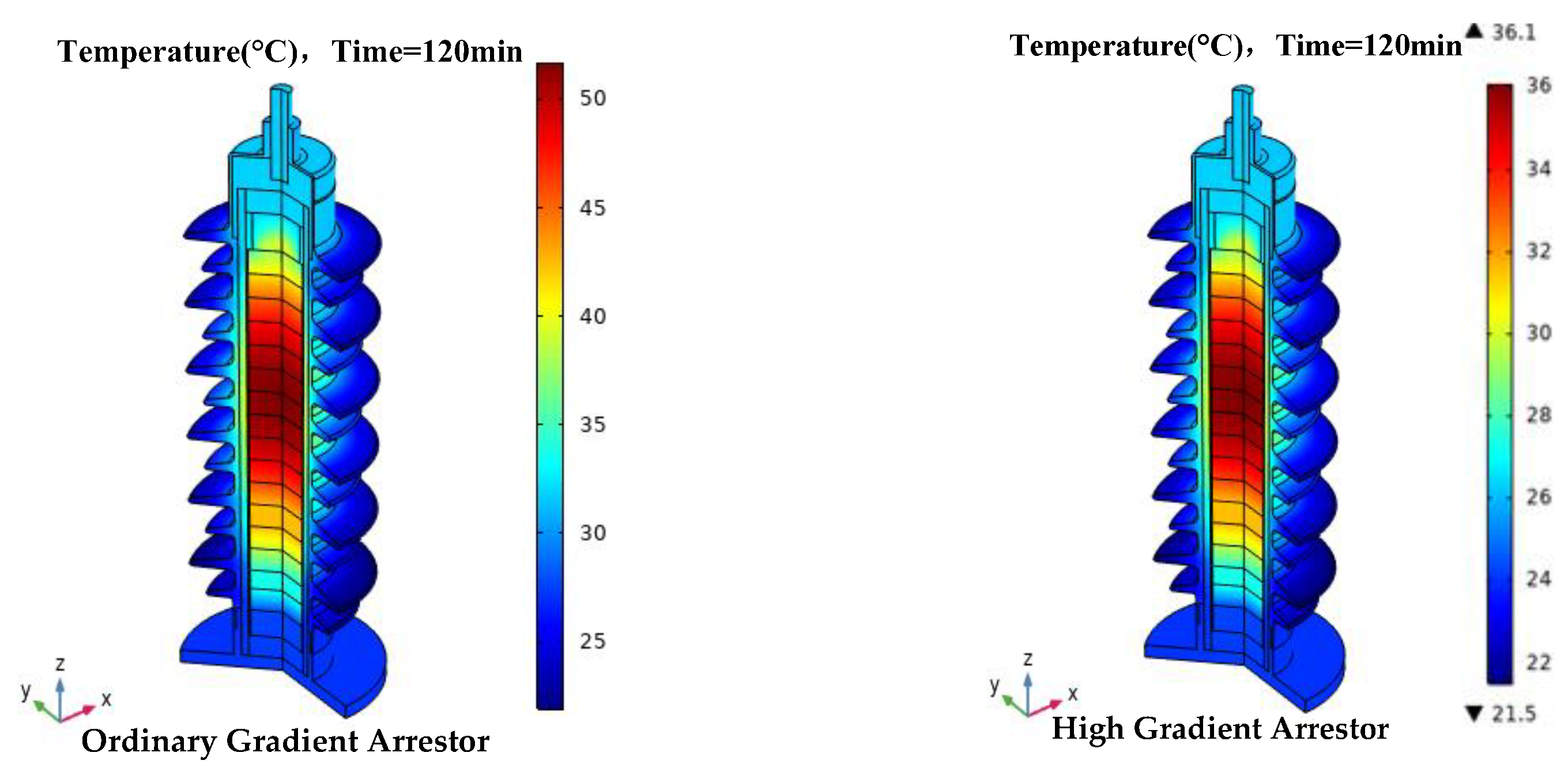
5. Thermal Distribution of an Arrestor Considering High-Frequency Overvoltage

Thermal Process of Arrestor under Power Frequency Operating Voltage

The power frequency voltage simulation was carried out for the arrestors of ordinary-gradient and high-gradient valve plates. The withstand conditions of the two types of arrestor valve plates are shown in Table 2.
At present, the single arrestor of the EMUs under consideration can withstand a voltage of 42 kV. For ordinary-gradient valve plates, the number of valve plates in a single arrestor is 14, and its operating voltage is 66.5 kV. The number of high-gradient valve plates in an arrestor of the same height, assuming that its action voltage is consistent with that of an ordinary-gradient valve plate arrestor, should be nine, and the rest should be set as aluminum pads, with all of them packaged in an epoxy resin pipeline and coated with silicone rubber. Our model was established by an electro-thermal coupling field in COMSOL to calculate the temperature-rise process and temperature distribution. When the applied voltage was 42 kV, the heat source was the power loss generated by the arrestor under the voltage, and the ambient temperature was 20 °C, the internal heat distribution of the arrestor was obtained at 0–120 min. The temperature distributions of the two kinds of arrestor are shown in Figure 9 and Figure 10 as a rainbow grid.
The maximum temperature increase process of an ordinary-gradient valve plate and a high-gradient valve plate under a power frequency condition was obtained, as shown in Figure 11.
When the applied voltage was 42 kV and the frequency changed, the temperature-rise process of the arrestor was as shown in Figure 12, Figure 13 and Figure 14.
Under the action of high-frequency voltage, the 0–120 min valve temperature increased as compared to normal circumstances, and the higher the voltage frequency, the more the temperature increased; the growth rate also increased. Figure 15 depicts the temperature rise of the valve under various voltage and frequency conditions.

6. Discussion of the Applicability of High-Gradient Valves under High-Order Harmonic Conditions

The common-gradient and high-gradient zinc oxide valve pieces can be compared using the test results of various voltage frequencies; when the same industrial-frequency voltage was applied, the total leakage current flowing through the common-gradient valve piece was about 1.45 times that of the high-gradient valve piece. Power frequency affected the leakage current, power loss, etc., of the arrestor valve piece. As indicated in Table 3, when a high-frequency harmonic voltage was applied, the general-gradient valve piece experienced a total leakage current that was approximately 1.34 times greater than that of the high-gradient piece, and showed a roughly 1.33 times greater active power loss.
The temperature distribution in arrestors under different high-frequency voltages is based on simulations, according to the impedance component of leakage current. The temperature-rise characteristic were obvious when the arrestor structure was the same.
Improving the potential gradient of the zinc oxide valve sheet could effectively reduce the value of the leakage current flowing through the valve sheet under different frequency voltages, and then reduce the active power loss generated on the valve sheet, extending the service life of the whole arrestor.

7. Conclusions

This paper describes research conducted on arrestor leakage current characteristics and arrestor thermal processes under high-frequency overvoltage. A wide frequency domain voltage test platform for the arrestor valve piece has been established, and the leakage current and the heat power of the arrestor have been measured. At the same time, the applicability of high-gradient valve pieces in electrified railroad overvoltage conditions has been promoted. The following are the findings:
(1) The leakage current characteristics of the arrestor valve sheet under high-frequency voltage conditions were obtained. When influenced by the voltage frequency, the higher the power supply frequency was under the same voltage, the larger the leakage current was. Under the 61st harmonic voltage, the high-gradient valve piece could withstand an 85% higher voltage than the ordinary valve piece.
(2) The microscopic morphological characteristics and element distribution characteristics of the arrestor valve sheet were examined. The ordinary valve sheet showed coarse grains on the observation scale of 20 μm, whereas the high-gradient surface grains were uniform and the lamellar layer was rare. The elemental composition distribution of ZnO in the ordinary-gradient valve sheet exhibited agglomeration, whereas the high-gradient valve sheet had a uniform distribution of ZnO elemental composition. The smaller the grain size, the more zinc oxide grains were accommodated per unit thickness, which is an important reason for the high potential gradient assumed by the zinc oxide valve sheet.
(3) The temperature-rise process of the arrestor under high-frequency voltage conditions was obtained, indicating the applicability of the high-gradient valve sheet in an electrified railroad. In the same withstand voltage case, the total leakage current flowing in the common-gradient valve piece was about 1.45 times that of the high-gradient valve piece; when high-frequency harmonic voltage was applied, the total leakage current flowing in the common-gradient valve piece was about 1.34 times that of the high-gradient valve piece, and the active power loss was about 1.33 times. Our research shows that, as long it is noted that external insulation was not considered, the high-gradient valve piece arrestor is more suitable for the frequent overvoltage condition of the electrified railroad.

Author Contributions

Conceptualization, J.S., Y.F. and K.Z.; methodology, J.S. and Y.F.; software, J.L.; validation, X.W. and S.Y.; formal analysis, K.Z.; investigation, J.S. and Y.F.; resources, Y.F.; data curation, J.L.; writing—original draft preparation, J.L.; writing—review and editing, K.Z.; visualization, Y.F.; supervision, S.Y.; project administration, K.Z.; funding acquisition, Y.F. All authors have read and agreed to the published version of the manuscript.

Funding

This research was funded by Fundamental Research Funds for the Central Universities (Science and technology leading talent team project, 2022JBQY008), the National Natural Science Foundation of China (51907003), the Scientific Research Project of China, Academy of Railway Sciences Group Co., Ltd. (2022YJ152), and the Science and Technology Project of the National Energy Group (SHTL-21-08).

Institutional Review Board Statement

Not applicable.

Informed Consent Statement

Informed consent was obtained from all subjects involved in the study.

Data Availability Statement

The data in the paper is availability and can be published by “coatings”.

Acknowledgments

The authors would like to thank reviewers for their pertinent comments that helped to improve the quality of this paper.

Conflicts of Interest

The authors declare no conflict of interest.

References

  1. Eda, K.; Iga, A.; Matsuoka, M. Degradation mechanism of non-Ohmic zinc oxide ceramics. J. Appl. Phys. 1980, 51, 2678. [Google Scholar] [CrossRef]
  2. Wang, S.; Ou, Q.; Lei, S.; Liu, H.; Mao, S.; Zhang, Q.; Liu, J.; Lv, F. Study on the Measurement of the On-Site Overvoltage and Internal Temperature Rise Simulation of the EMU Arrestor. Appl. Sci. 2022, 12, 312–321. [Google Scholar]
  3. Lu, H.; Zhu, F.; Liu, Q.; Li, X.; Tang, Y.; Qiu, R. Suppression of Cable Overvoltage in a High-Speed Electric Multiple Units System. IEEE Trans. Electromagn. Compat. 2019, 61, 361–371. [Google Scholar] [CrossRef]
  4. Li, M.; Wen, Y.; Sun, X.; Wang, G. Analysis of Propagation Characteristics of Electromagnetic Disturbance from the Off-Line of Pantograph-Catenary in High-Speed Railway Viaducts. Chin. J. Electron. 2020, 29, 966–972. [Google Scholar] [CrossRef]
  5. Zhang, J.; Han, Y.; Li, L.; Deng, J.; Luo, X.; Meng, Y.; Sun, Q. Study on the Unipolar Impulse Aging of ZnO Varistors and Their Condition Monitoring Methods Based on the Basic and Even-Order Harmonics of the Leakage Current Resistive Component. IEEE Trans. Power Deliv. 2022, 37, 4888–4898. [Google Scholar] [CrossRef]
  6. Hoshino, T.; Maruyama, S.; Sakakibara, T. Simulation of Propagating Electromagnetic Wave Due to Partial Discharge in GIS Using FDTD. IEEE Trans. Power Deliv. 2009, 24, 153–159. [Google Scholar] [CrossRef]
  7. Amiji, N.; Tanno, Y.; Okuma, H.; Kan, M. Homogeneity of Zinc Oxide Varistors. Adv. Ceram. Mater. 1986, 1, 232–236. [Google Scholar] [CrossRef]
  8. Zhang, L.; Yu, C.; Zhang, L.; Liu, W.; Wu, K.; Li, S.; Li, J. A statistical approach for effectively analyzing the grain size distribution along the thickness direction in commercial ZnO-based varistor ceramics. In Proceedings of the 2018 Condition Monitoring and Diagnosis (CMD), Perth, WA, Australia, 23–26 September 2018; IEEE: New York, NY, USA, 2018; pp. 1–6. [Google Scholar]
  9. Kejian, S.; Mingli, W.; Agelidis, V.G.; Hui, W. Current harmonics of three-level neutral-point-clamped electric multiple unit rectifiers: Analysis, simulation and testing. IET Power Electron. 2014, 7, 712–721. [Google Scholar] [CrossRef]
  10. Wu, J.; Hu, J.; Chen, S.; He, J. Harmonic Characteristics of Leakage Currents of ZnO Varistors Under Impulse Aging. IEEE Trans. Power Deliv. 2017, 32, 1758–1767. [Google Scholar] [CrossRef]
  11. Yasuda, E.J. Gapless Surhe Arrestors or Power Systems Applications Volume 2 BPA’s Field Installation and Evaluation of 1200-kV Arrestors: EPRI Final Report, EL-3166; EPRI: Palo Alto, CA, USA, 1983. [Google Scholar]
  12. Zhang, Q.; Wang, S.; Sun, K.; Dong, X.; Liu, M.; Lü, F. Study on operation voltage monitoring and electro thermal coupling simulation of electric multiple unit (EMU) roof arrester. High Volt. 2022, 7, 357–368. [Google Scholar] [CrossRef]
  13. Eda, K. Destruction mechanism of ZnO varistors due to high currents. J. Appl. Phys. 1984, 56, 2948–2955. [Google Scholar] [CrossRef]
  14. Gustavsen, B.; Portillo, A.; Ronchi, R.; Mjelve, A. High-Frequency Resonant Overvoltages in Transformer Regulating Winding Caused by Ground Fault Initiation on Feeding Cable. IEEE Trans. Power Deliv. 2018, 33, 699–708. [Google Scholar] [CrossRef] [Green Version]
  15. Xia, X. Analysis and treatment of harmonic overvoltage in wati Railway traction network. Electr. Railw. 2021, 32, 118–121. [Google Scholar]
  16. Zhang, B.; Li, G.; Zhang, C.; Song, J.; Chen, L.; Su, N. Internal Temperature Rise of MOA Under Pollution Condition. High Volt. Eng. 2011, 37, 2065–2072. [Google Scholar]
  17. Seyyedbarzegar, S.M.; Mirzaie, M. Application of finite element method for electro-thermal modeling of metal oxide surge arrestor. Comput. Appl. Eng. Educ. 2015, 23, 910–920. [Google Scholar] [CrossRef]
  18. Vanadamme, L.K.J.; Brugman, J.C. Conduction mechanisms in ZnO varistors. J. Appl. Phys. 2008, 51, 4240–4244. [Google Scholar] [CrossRef]
  19. Sun, J.; Ding, F.; Lv, Y.; Ren, J.; Song, S.; Li, T.; Zhi, Q.; Guo, C. Leakage Current Characteristics and Aging Assessment Technology of Roof Arrestor under Ultra Harmonics Overvoltage. IET High Volt. 2021, 3, 346–356. [Google Scholar]
  20. Cojocaru-Mirédin, O.; Schmieg, J.; Müller, M.; Weber, A.; Ivers-Tiffée, E.; Gerthsen, D. Quantifying Lithium in Lithium-ion battery solid electrolyte by atom probe tomography correlated with high-resolution scanning electron microscopy. Microsc. Microanal. 2022, 28, 760–762. [Google Scholar] [CrossRef]
  21. Zhao, X.; Meng, P.; Yang, X.; Yuan, Z.; Hu, J.; Li, Q.; He, J. Gradient structure design of zinc oxide varistor microsphere composites for efficient electric field grading. Compos. Part A Appl. Sci. Manuf. 2022, 153, 106731. [Google Scholar] [CrossRef]
  22. Li, S.; Li, J.; Liu, W.; Lin, J.; He, J.; Cheng, P. Advances in ZnO varistors in China during the past 30 years-fundamentals, processing, and applications. IEEE Electr. Insul. Mag. 2015, 31, 35–44. [Google Scholar] [CrossRef]
  23. Shichimiya, S.; Yamaguchi, M.; Furuse, N.; Kobayashi, M.; Ishibe, S. Development of advanced arrestors for GIS with new zinc-oxide elements. IEEE Trans. Power Deliv. 1998, 13, 465–471. [Google Scholar] [CrossRef]
  24. Liu, W.; Xiao, J.; Jin, S.; Yang, S.; Gao, M.; Zhang, Y. Analysison Damp Defect of 500 kV Zinc Oxide Arrester Based on Field Circuit Coupling. Insul. Surge Arresters 2022, 1, 118–125. [Google Scholar]
  25. Zeng, G.; Wang, X.; Liu, S.; Liu, B.; Zhang, S.; Liu, B.; Wei, Z.; Wang, Z.; Li, S. Simulation Analysis of Temperature Rise Distribu-tionCharacteristics of Damp Arrester. Hubei Electr. Power 2020, 44, 34–41. [Google Scholar]
  26. Fang, Z.; Wu, X.; Guo, J.; Xie, P.; Hu, J.; Li, C. Heat Dissipation Model of Arrester Under Transient Time-varying Load. High Volt. Eng. 2020, 46, 34–41. [Google Scholar]
  27. Zha, J.; Dang, Z.; Zhao, K.; Zheng, X.; Li, S. Prominent nonlinear electrical conduction characteristic in T-ZnOw/PTFE composites with low threshold field. IEEE Trans. Dielectr. Electr. Insul. 2012, 19, 567–573. [Google Scholar]
  28. Zhu, Y.; Yang, J.; Shen, J. Analysis and research on contact ablation of high voltage circuit breaker. Power Equip. 2022, 35, 5. [Google Scholar]
  29. Wu, Q.; Wang, Y.; Wang, Y.; Wang, J.; Lan, L.; Deng, Y.; Wen, X.; Luo, B.; Xiao, W. Ablation state assessment of SF6 circuit breaker contacts based on BP neural network and mean impact value. Energy Rep. 2022, 8, 874–883. [Google Scholar] [CrossRef]
Figure 1. Arrestor explosion under high harmonic action.
Coatings 13 00497 g001
Figure 2. Model of arrestor simulation.
Coatings 13 00497 g002
Figure 3. Test tooling and two kinds of arrestor valves.
Coatings 13 00497 g003
Figure 4. I-U characteristics of the two kinds of valve plate. (a) I-U characteristics of ordinary plate; (b) I-U characteristics of high-gradient plate.
Coatings 13 00497 g004
Figure 5. Power variation curve of D71 valve plate. (a) Power characteristics of general plate; (b) Power characteristics of high-gradient plate.
Coatings 13 00497 g005
Figure 6. Surface morphology of D71 valve plates. (a) Surface morphology of ordinary plate; (b) Surface morphology of high-gradient plate.
Coatings 13 00497 g006
Figure 7. Assembly of surface elements of D71 valve plate. (a) Surface elements for ordinary-gradient valve plate; (b) Surface elements for high-gradient valve plate.
Coatings 13 00497 g007
Figure 8. Elemental configuration map of D71 valve plate. (a) Elemental configuration map of ordinary-gradient valve plate; (b) Elemental configuration map of high-gradient valve plate.
Coatings 13 00497 g008
Figure 9. Temperature distribution of 60 min high-gradient and ordinary-gradient arrestor under power frequency voltage.
Coatings 13 00497 g009
Figure 10. Temperature distribution of 120 min high-gradient and ordinary-gradient arrestor under power frequency voltage.
Coatings 13 00497 g010
Figure 11. The maximum temperature of ordinary-gradient and high-gradient valve under power frequency condition.
Coatings 13 00497 g011
Figure 12. Temperature distribution of different valve arrestors at 1050 Hz for 120 min.
Coatings 13 00497 g012
Figure 13. Temperature distribution of different valve arrestors at 2050 Hz for 120 min.
Coatings 13 00497 g013
Figure 14. Temperature distribution of different valve arrestors at 3050 Hz for 120 min.
Coatings 13 00497 g014
Figure 15. The maximum temperature of ordinary-gradient and high-gradient valve under high frequency condition.
Coatings 13 00497 g015
Table 1. Size and parameters of test sample of zinc oxide valve plate.
Sample SpecificationDiameter/mmThickness/mmPotential Gradient V/mmDC Reference Voltage
/kV
D71 (normal gradient)71222144.75
D71 (high gradient)71223277.30
Table 2. Effectiveness of several gradient valve samples.
NameOrdinary-Gradient ValveHigh-Gradient Valve Plate
specification/mmD71 × 22D71 × 22
average gradient/V·mm214327
dc reference voltage/kV4.757.3
Table 3. Contrasts in test outcomes for zinc oxide valves with various potential gradients.
General-Gradient Valve PieceHigh-Gradient Valves
Frequency/Hz105020503050105020503050
Total leakage current/mA24.6938.4347.0918.3828.8536.09
Resistive leakage current/mA2.763.954.412.052.963.38
Active power loss/W8.7812.5714.046.499.3810.69
Disclaimer/Publisher’s Note: The statements, opinions and data contained in all publications are solely those of the individual author(s) and contributor(s) and not of MDPI and/or the editor(s). MDPI and/or the editor(s) disclaim responsibility for any injury to people or property resulting from any ideas, methods, instructions or products referred to in the content.

