Article

Study on Sintering Behavior of Reaction-Cured Glass Coating

1
National Key Lab for Precision Hot Processing of Metals, Harbin Institute of Technology, Harbin 150001, China
2
Center for Composite Materials and Structures, Harbin Institute of Technology, Harbin 150080, China
3
Center of Analysis and Measurement, Harbin Institute of Technology, Harbin 150001, China
4
Shenzhen STRONG Advanced Materials Research Institute Co., Ltd., Shenzhen 518035, China
*
Authors to whom correspondence should be addressed.
Coatings 2023, 13(2), 463; https://doi.org/10.3390/coatings13020463
Submission received: 30 December 2022 / Revised: 13 February 2023 / Accepted: 16 February 2023 / Published: 17 February 2023

Abstract

:
High-emissivity coatings constitute an essential component of reusable thermal protection systems, determining the success or failure of hypersonic spacecraft. Reaction-cured glass coating is the basis for all current high-emissivity coatings, and the study of its sintering behavior is of great scientific significance for the development and performance enhancement of the coating. Microstructures and phase compositions of the samples before and after the sintering process were determined using SEM, XRD, and EDS. The sintering temperature, inserting temperature, and heating rate were systematically investigated. The results show that the effects of the sintering temperature, inserting temperature, and heating rate on the coating occur in decreasing order. The optimum condition for coating sintering in this study is an insertion temperature of 1100 °C, a heating rate of 10 °C/min, and a sintering temperature of 1200 °C, and a crack-free and containing SiB4 borosilicate glass coating was successfully prepared.

1. Introduction

Reusable hypersonic vehicles re-enter the atmosphere multiple times at flight speeds of over Mach 5, resulting in a hostile aerodynamic heating environment on the fuselage surface [1,2,3]. Thermal protection systems (TPS) and materials are imperative to safeguard the vehicle’s internal structures and electronic equipment from extreme heating on external surfaces. Fibrous ceramic insulators, also known as rigid insulative tiles, are considered to be one of the main components of the current large-area TPS due to their high-temperature capacity (up to 1500 °C), low thermal conductivity (0.06–0.42 W/(m·K)), and low density (0.14–0.40 g/cm3) [4,5,6]. The top surface and four sides of each insulator usually need to be covered with a high-emissivity coating, which could reduce the surface temperature by radiating heat toward the surrounding environment [7,8,9,10]. Therefore, high-emissivity coatings with reliable performance are an indispensable and critical part of TPS [11].
With the continuous increase in the applied temperature of ceramic insulators, the development of high-emissivity coatings has also undergone three main stages in terms of composition. The reaction-cured glass coating (RCG), developed by the NASA Ames Research Center, is a single-phase glass coating with borosilicate glass as the main component supplemented with a small amount of SiB4 [12]. SiB4 is considered a processing aid and emittance agent. After that, a new generation of toughened uni-piece fibrous insulation coating (TUFI) was developed on the basis of RCG for mechanical property requirements [11,13]. Compared with the past coatings, the composition and structure of TUFI have changed. The introduction of MoSi2 allowed the coating to radiate heat efficiently in a wider range of wavelengths at a higher temperature (~1500 °C), and the gradient structure endows greater thermo shock resistance and higher impact resistance to the coating. In the same vein, a newly developed high-efficiency tantalum-based ceramic (HETC) composite structure was developed by adding TaSi2 to achieve better extreme high-temperature capacity (~1650 °C) and radiation performance than TUFI [14]. The major components of the HETC coating are borosilicate glass, TaSi2, MoSi2, and SiB4 or SiB6, and the three additives are responsible for the coating’s emittance and self-healing at different temperatures. To summarize, the high-emissivity coating primarily consists of a ceramic glass coating, and in order to achieve efficient insulation in a full temperature range and wide wavelengths, emittance agents with excellent thermo-resistant properties were gradually introduced to the coating. It is worth mentioning that the RCG coating is the basis for subsequent coatings. The study of its sintering behavior is of great scientific significance for the development and performance enhancement of high-emissivity coatings. In addition, because of the practical achievements of HETC, many researchers have conducted studies related to high-emissivity coatings. A series of glass-based coatings with varied components for thermal protection systems were designed and developed, including the MoSi2-borosilicate glass coating [7,8,15], MoSi2-ZrO2-borosilicate glass coating [16], MoSi2-SiB4-borosilicate glass coating [11,12,13], MoSi2-BaO-Al2O3-SiO2 coating [9], MoSi2-aluminoborosilicate glass coating [10], WSi2-Si-SiO2 glass coating [17], TaSi2-MoSi2-Al2O3-borosilicate glass coating [18], WSi2-MoSi2-Si-SiB6-borosilicate glass coating [19], etc. These high-emissivity coatings all exhibit excellent temperature resistance and radiation capabilities.
In previous articles, the focus was more on the effects of different additives on the coating. There have been, however, very few researchers who have paid attention to the influence of sintering parameters on the coating. In this paper, the process factors, sintering temperature, inserting temperature, and heating rate, were investigated. The microstructure and phase composition of the coating after sintering were characterized. The optimal sintering conditions for RCG coating were obtained.

2. Materials and Methods

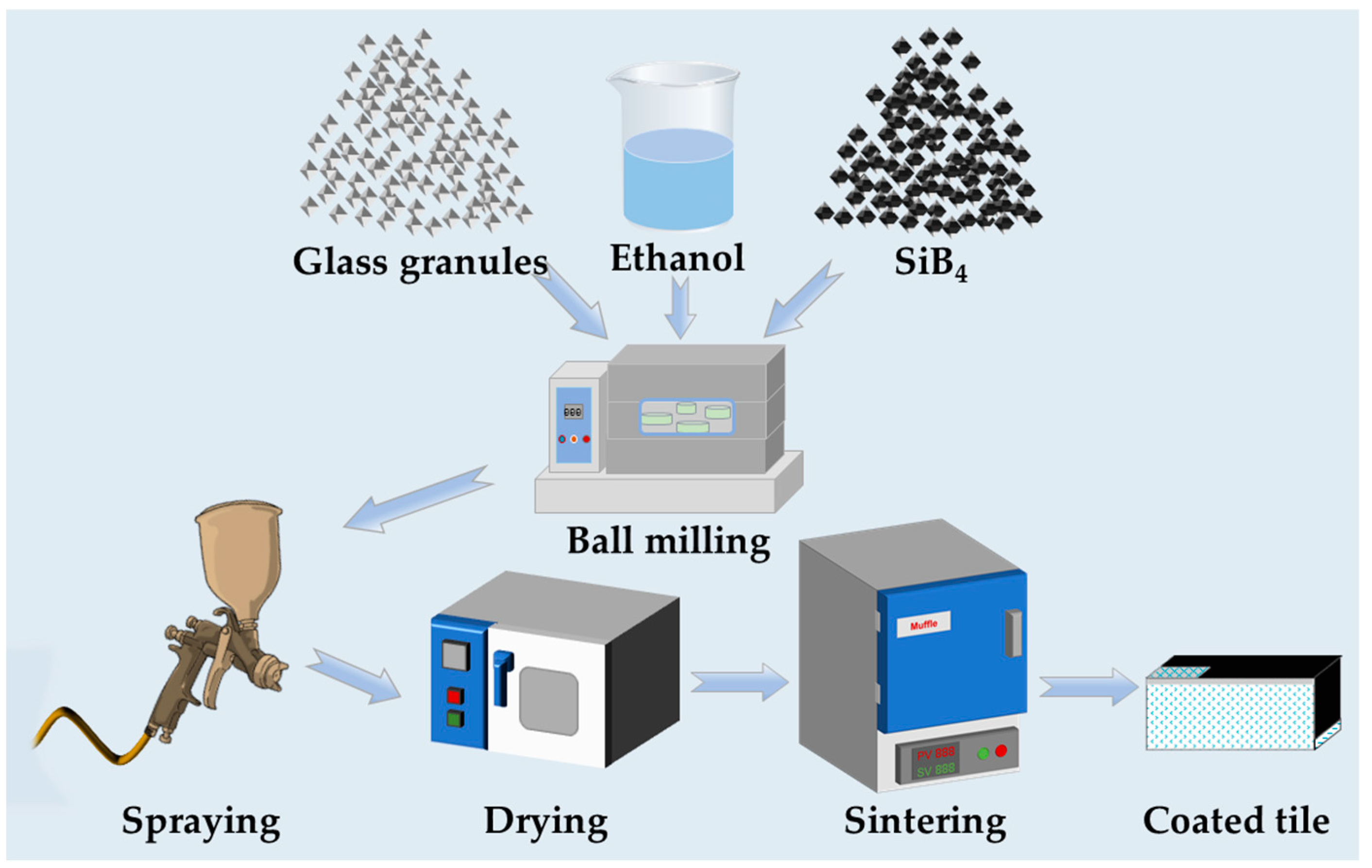
2.1. Preparation of RCG Coatings

Silica fibrous insulators fabricated from chopped silica fibers were adopted to be substrates (roughly 50 mm × 50 mm × 20 mm) in this study. The insulator was self-made, and the preparation process was described in reference [5]. The coating was prepared using the spraying method and sintered in air. The borosilicate glass (BSG) granules (200 mesh), made of 5 wt.% boron oxide and 95 wt.% silica, and high-purity SiB4 (1–5 µm) for coating preparation were self-made [20]. A ball-milling process that further pulverized and mixed the ceramic powders was applied to prepare the spraying slurry. The two kinds of ceramic powders and ethanol were added to a nylon jar in succession and ball-milled via a planetary mill machine at a rotation speed of 300 rpm for 24 h. Typically, the mass ratio of glass granules, SiB4, ethanol, and zirconia balls is 1:0.05:0.8:1.8. Figure 1 illustrates the overall preparation process for the RCG coating on the silica fibrous insulator. The gun pressure was approximately 4 atm during the spraying process. After spraying, the coated samples were dried at 80 °C for 24 h. Sintering process factors including the sintering temperature, inserting temperature, heating rate, holding time, and removing temperature have a significant impact on the morphology, microstructure, and properties of RCG coating. The holding time at the sintering temperature was set at 0.5 h. After that, the samples were allowed to cool down naturally to 800 °C and were removed from the muffle furnace quickly. Except for the two fixed factors, the rest will be studied and discussed below, and specific parameters can also be found in Table 1.

2.2. Characterization

The surface morphology and microstructure of coating samples were characterized by scanning electron microscopy (SEM) with Merlin Compact CARL ZEISS (Oberkochen, Germany) equipment operated at 20 kV. The elements distribution of the coating samples was obtained by an energy dispersive spectrometer (EDS, Merlin Compact, CARL ZEISS, Oberkochen, Germany). An X-ray diffractometer (X’pert PANalytical, Almelo, The Netherland) was used to identify the phase compositions of the coating samples with Cu-Kα radiation at 1.54 Å, 40 kV, and 40 mA. X-ray photoelectron spectroscopy (XPS) spectra of samples before and after sintering coating were obtained using an ESCALAB-250XI spectrometer (Thermo Fisher Scientific, Waltham, MA, USA) with monochromatic Al-Kα as the X-ray source (1486.6 eV).

3. Results

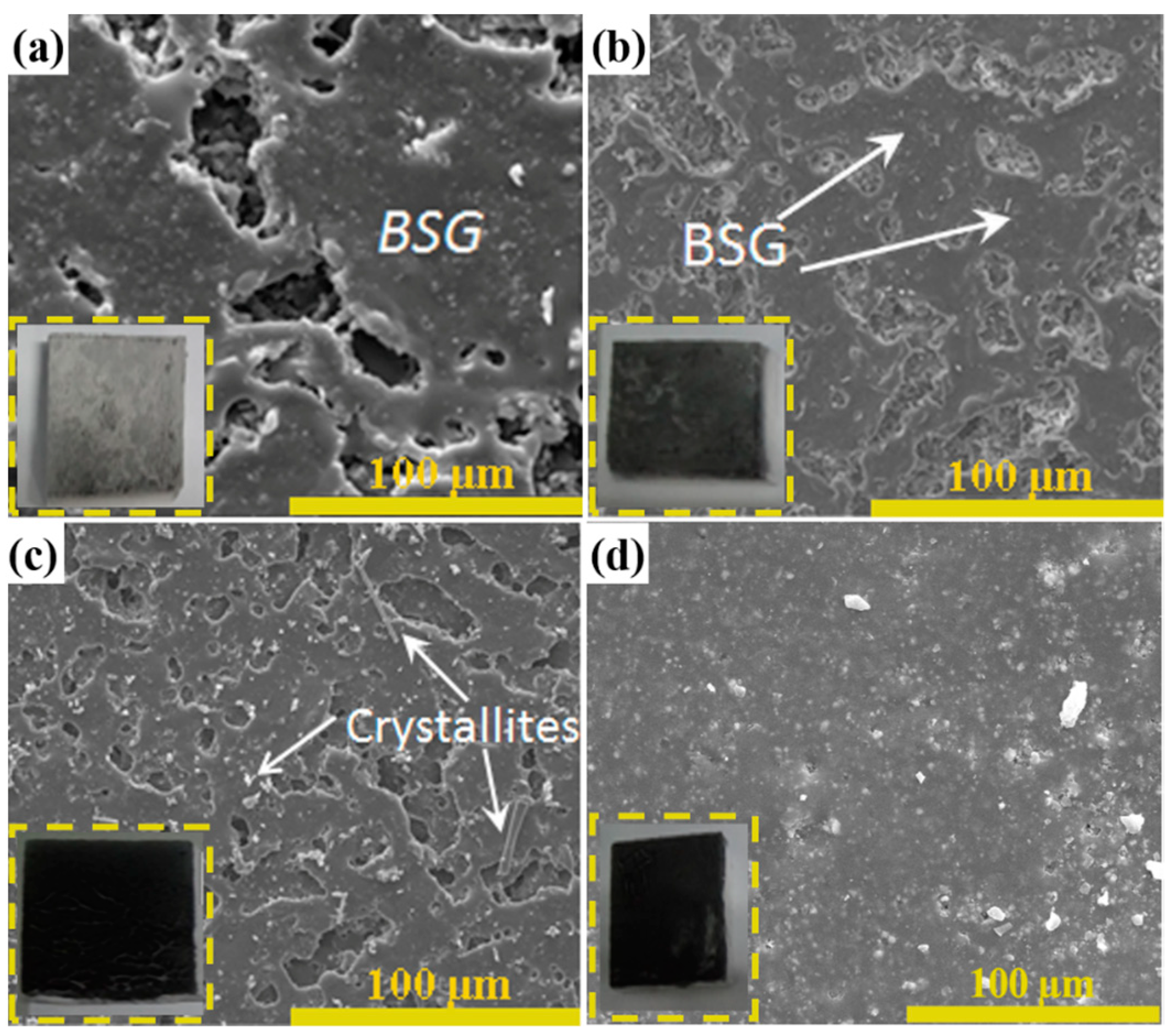
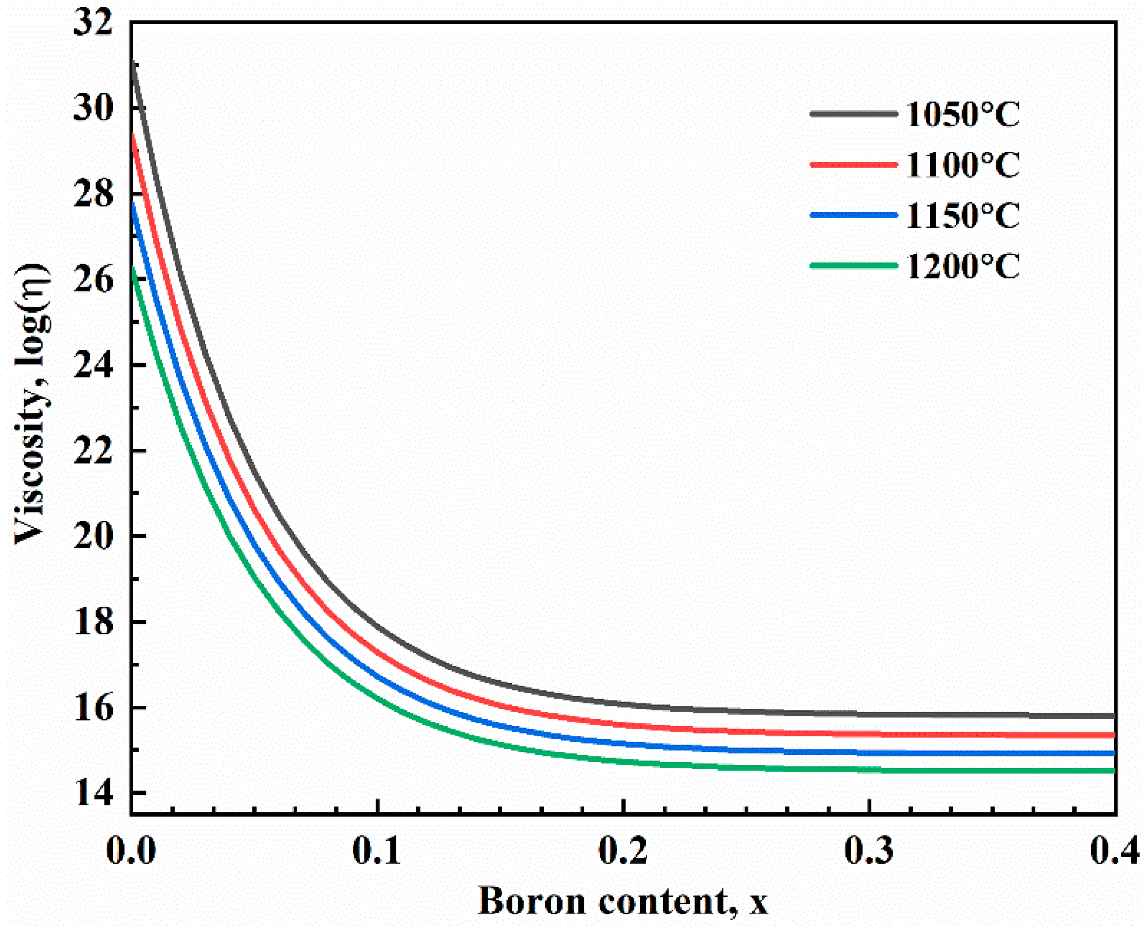
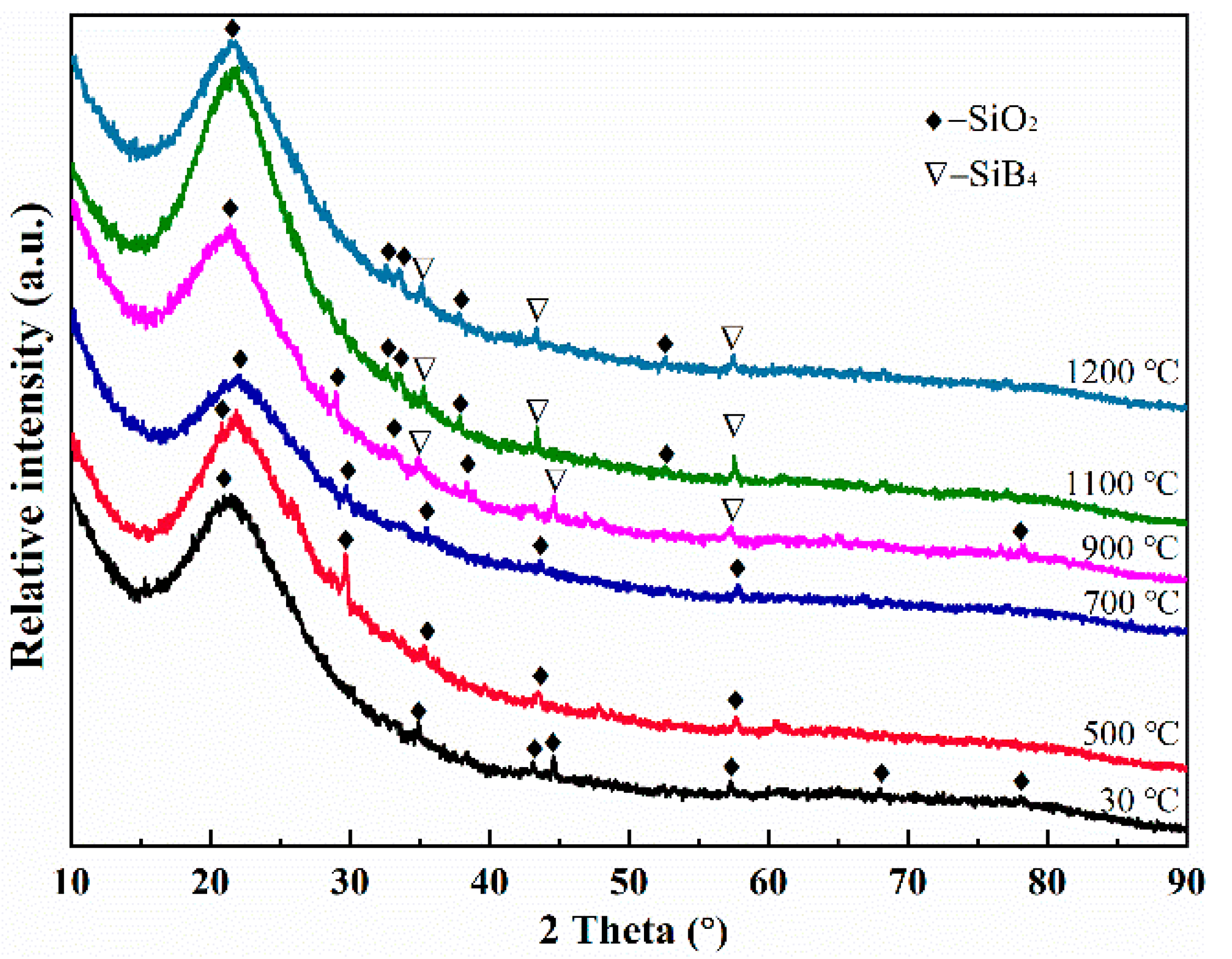
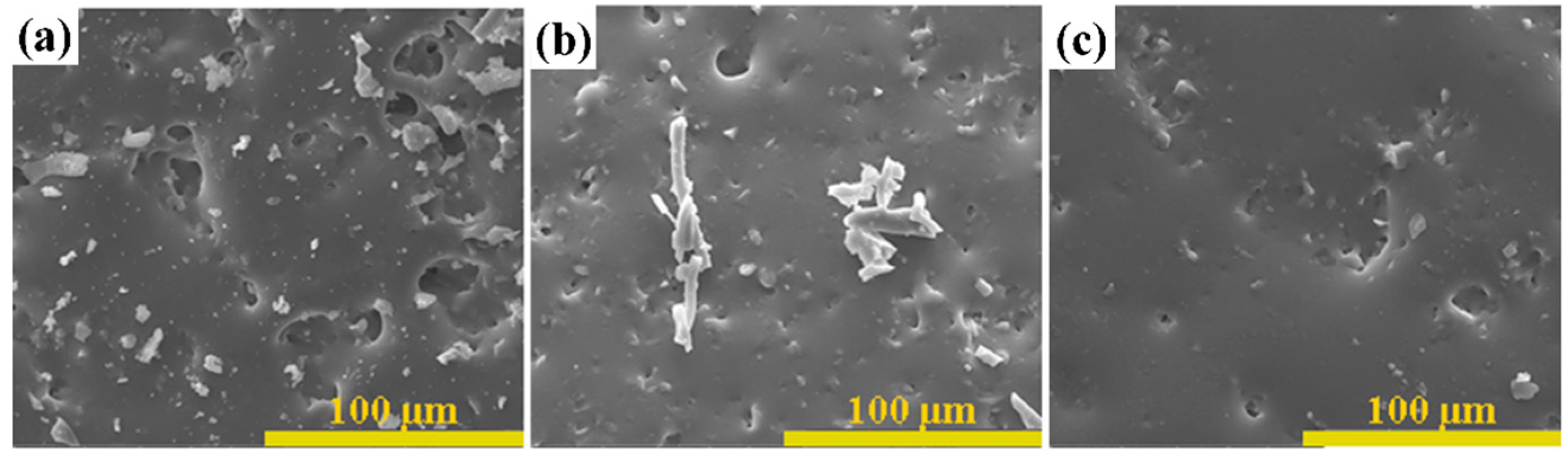
3.1. Sintering Temperature

The sintering temperature is a crucial control factor for the preparation of glass coating, affecting the micromorphology and performance of RCG. In regard to passive thermal protection systems, RCG coatings must be integrated and dense. This is because they can provide improved protection for porous substrates against airflow erosion during prolonged exposure to high temperatures and high velocities. On the other hand, a high-emissivity coating such as RCG differs from an oxidation protective coating. The RCG coating needs to emit the heat of the fuselage through the radiative agent (SiB4). In the event that defects lead to excessive thermal oxidation of SiB4, this will inevitably weaken the coating’s radiative ability. In order to obtain the desired coating, after drying, the samples were sintered at different temperatures from 1050 to 1200 °C. The samples were inserted into the furnace at 30 °C and ramped up to the predetermined sintering temperature at a heating rate of 10 °C/min.
Figure 2 compares the surface micromorphology of RCG coatings sintered at varied temperatures, and the insets are macrophotographs of the corresponding coatings. Looking at the insets in Figure 2a–d, it is apparent that the color of samples gradually deepens as the sintering temperature increases. Samples sintered at 1150 and 1200 °C are darker black (in Figure 2c,d), whereas the coating sintered at 1050 °C is near transparent (in Figure 2a). In fact, the off-white color is a fibrous insulation substrate. The degree of thermal oxidation of SiB4 is the dominant factor in the color transition of coatings. It is well accepted that the more oxidized SiB4 is, the more transparent the coating color will be, and the higher the temperature, the faster the oxidation reaction. However, the most intriguing finding is that the higher the sintering temperature, the darker the RCG coating color. In order to determine causality, the microscopic morphology of the samples sintered at different temperatures was further compared. What stands out in Figure 2 is the significant change in the micromorphology of coating surfaces at varying temperatures. It can be found that as the sintering temperature increases, the coating transforms from a rough surface with a large number of deep crater-like pores to a dense surface with a small number of pores. Overall, the surface of the coating samples is composed of continuous and dense regions and isolated microporous regions. A small number of fibrous cristobalite crystallites also can be found in Figure 2c, which originate from the substrate and were introduced during sample preparation. Based on the above analysis, it can be seen that the most likely reason for the darkening of the coating is that the dense coating surface protects the inner SiB4 particles from oxidation. The specific thermal oxidative reaction of SiB4 is shown in Reactions (1) and (2). During the heating stage, the oxidation of SiB4 takes place according to Reaction (1), and the oxidative products, SiO2 and B2O3, form a new BSG phase due to their good compatibility following Reaction (2). The BSG can seal the pores and creaks, which is the stem of the self-healing ability of the RCG coating in small cracks. Further, the color of coatings at low sintering temperatures may be related to the viscosity of BSG.
SiB4(s) + O2(g) = SiO2(s) + B2O3(s)
SiO2(s) + B2O3(s) = SiO2(s)·B2O3(s)
The sintering temperature directly affects the viscosity of the borosilicate glass phase, which is the main phase of the RCG coating. The empirical relationship for the viscosity of BSG with its boron content and temperature, reported by Yan et al. [21], is described as:
log   η = 3.11 19.2 exp ( 24 x ) + 1.68 × 10 4 T + 4.56 × 10 4 exp ( 22 x ) T
where η is the viscosity, x is the boron content by weight fraction and is limited to 0 < x < 0.4, and T is the temperature. Figure 3 displays the plot of BSG’s viscosity as a function of temperature. As can be seen in Figure 3, the viscosity of BSG decreases with increasing boron content, especially at a boron content below 10 wt.%. Furthermore, it is apparent from Figure 3 that viscosity decreases with increasing temperature. Given the recipe for the RCG coating in this study, it can be calculated that the mass fraction of boron is less than 10%, which means that the coating has a relatively high viscosity and is difficult to spread unless the sintering temperature is high enough. Therefore, at a low sintering temperature, the formed BSG may be too viscous to close the pores around the SiB4 particles, resulting in the particles being continuously oxidized to appear transparent. According to our previous research [22], the temperature of the initial oxidation of SiB4 is approximately 650 °C, and the temperature of secondary thermal oxidation, due to the volatilization of B2O3, is approximately 1150 °C. Hence, in order to account for the structural and functional requirements of RCG coatings, 1200 °C is the optimal temperature for sintering.

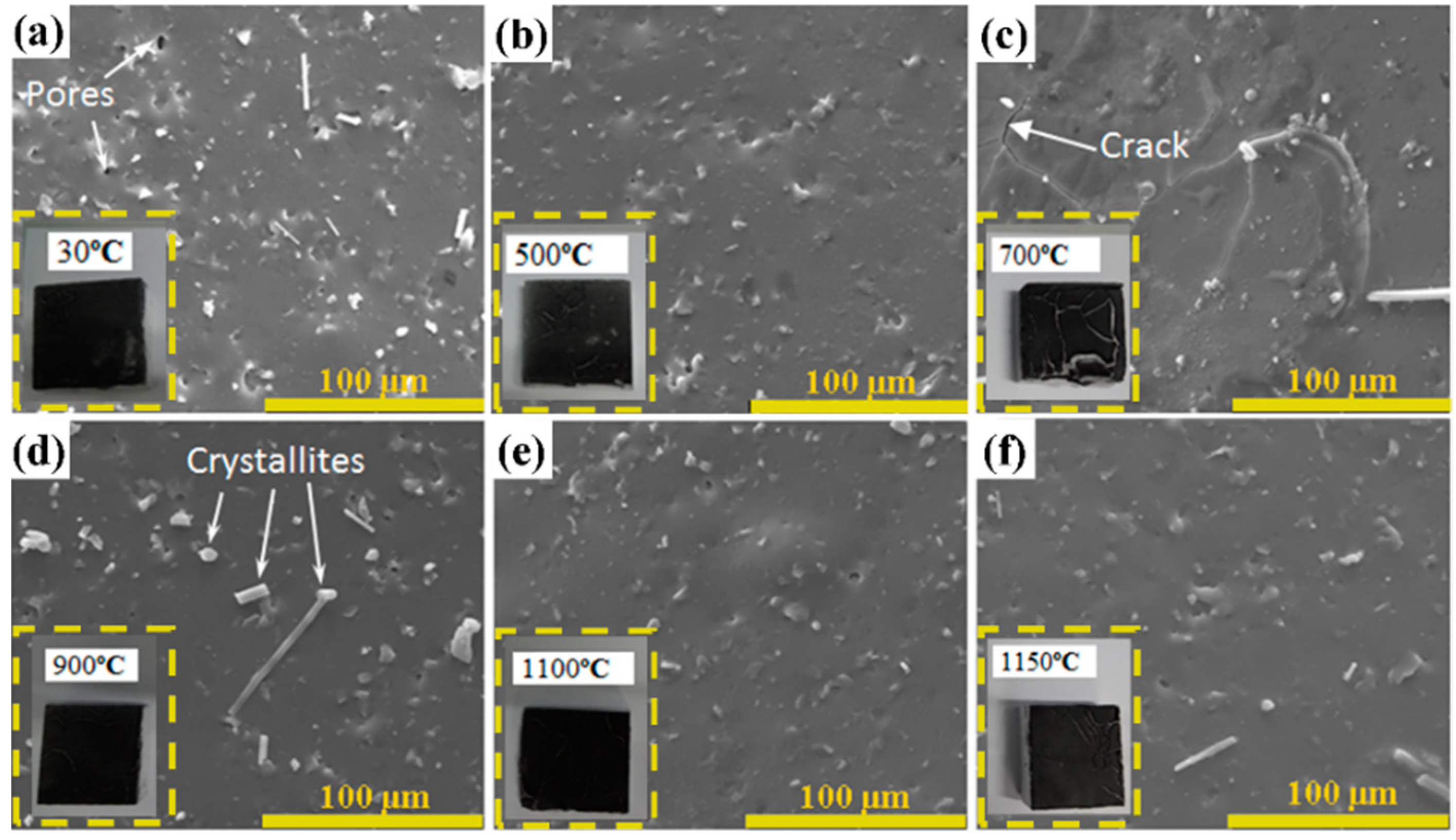
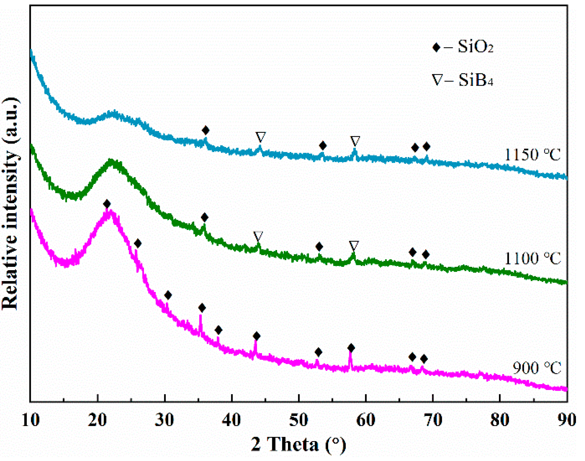
3.2. Inserting Temperature

On the basis of the above analysis, it is clear that SiB4 will inevitably be oxidized during the RCG sintering process, and the oxidation reaction is beneficial for coating sintering. However, improper inserting temperatures can cause the excessive oxidation of SiB4, which is detrimental to RCG’s emissive properties. Figure 4 shows the surface micromorphology of coatings inserted at different temperatures, and the insets are macrophotographs of the corresponding coatings. The coatings were sintered at 1200 °C with a heating rate of 10 °C/min.
Macrophotographs of the coatings show a deeper black, indicating that the functional additive added in a small amount was still present. From the insets of Figure 4b,c,f, it can be seen that cracks appear on the coating surface, which may have been attributed to the excessively fast heating rate. Comparing the microscopic morphology of samples at different insertion temperatures, all of the coatings present a glassy, dense, and integral state, except for the sample inserted at 700 °C with microcracks. Furthermore, fibrous cristobalite (PDF-#39-1425) crystallites are also found in Figure 4d. Meanwhile, in order to determine the remaining SiB4 in the coating, XRD patterns of the coating at varying insertion temperatures are displayed in Figure 5. These coatings are composed of an amorphous BSG phase alongside a small amount of crystalline silica, and the presence of SiB4 (PDF-#35-0777) can still be detected in samples inserted at 900 °C and above. The absence of SiB4 in samples below 700 °C might be associated with thermal oxidation. Trace fibrous crystalline silica may form during sintering as a result of the crystallization of amorphous phases, such as the coating itself or fibers of the substrate. In general, therefore, the inserting temperature of the RCG coating for sintering is preferably 900 °C or above.

3.3. Heating Rate

The heating rate plays a significant role in determining the functionality and densification of RCG coatings. At the same inserting temperature, a lower heating rate takes longer to reach the intended temperature. In other words, the SiB4 particle needs to undergo a longer oxidation duration before a protective layer is formed on its surface. Based on the above considerations, comparison experiments were implemented. The samples were inserted at 900, 1100, and 1150 °C, respectively. They were heated up to 1200 °C at 3 °C/min and then held for 0.5 h, as shown in Figure 6. Figure 6a shows that for the sample inserted at 900 °C, a large number of micropores with a pore size of 5~30 μm appear on the undulating coating surface. Micropores are still visible in the 1150 °C sample (Figure 6c). However, the samples inserted at the same temperature but heated at 10 °C/min exhibit a typical dense morphology with hardly any micropores in Figure 4d,f. There is no doubt that the heating rate is the main reason for this difference. The SiB4 particles undergo longer thermal oxidation at a lower heating rate, accompanied by severe volatilization of B2O3. According to Figure 3, the reduction of the boron element at low levels causes a significant increase in the viscosity of RCG coating. This means that the volatilization of boron oxide in turn leads to a surge in the local viscosity of the coating. Additionally, the increased viscosity also results in the liquid BSG failing to seal the pores between the particles in time to form effective protection for the internal functional additive. To investigate the phase compositions of surfaces, the XRD patterns of the coatings, sintered at 1200 °C with a heating rate of 3 °C/min, are shown in Figure 7. The main phase of the sample inserted at 900 °C is dominated by amorphous BSG, while the intensity of SiB4 diffraction peaks disappears. This confirms that the sample did undergo a more severe thermal oxidation process than the sample in Figure 4d, to the extent that SiB4 was not detected. It is therefore obvious that a relatively higher heating rate of, for example, 10 °C/min is more favorable for the sintering of the RCG coating.

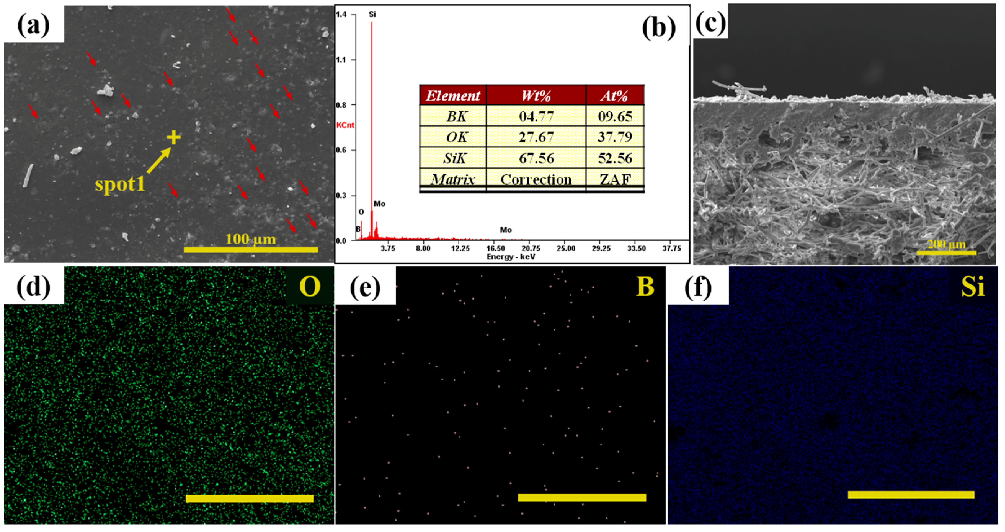
3.4. Comprehensive Characterization

In previous work, the effects of sintering temperature, inserting temperature, and heating rate on the RCG coating have been systematically determined. For the application requirements of thermal protection systems, the prepared RCG must be structurally and functionally stable. Accordingly, the RCG coating was prepared with a sintering temperature of 1200 °C, an inserting temperature of 1100 °C, and a heating rate of 10 °C/min, and the surface micromorphology and the distribution of different elements were analyzed, as shown in Figure 8. Figure 8a–c show the surface and cross-sectional microscopic morphology of the as-prepared RCG coating, respectively. It can be seen that the coating surface is smooth, dense, and lacks micropores or cracks, which is similar to the morphological characteristics of the reported coating [23,24]. After sintering, SiB4 particles can still be observed from the red arrows in Figure 8a. In addition, the cross-section view shows that the thickness of the coating is ~200 µm and the internal state is dense, which indicates that the functional additive particles have been surrounded by the BSG phase. The bond between the coating and the substrate is also intact and well compacted. The EDS analysis of the dark continuous phase at spot 1 (Figure 8b) indicates that the main elements are Si, O, and a small amount of B, suggesting that it is a mixture of SiO2 and B2O3. Figure 8d–f show the surface distribution of O, B, and Si elements, where the content of B is significantly lower than the others. This is consistent with Figure 8b, indicating that element B is still detectable due to its low volatilization during the sintering process.
The chemical state of the coating before and after sintering is further investigated by XPS, which can directly measure the chemical composition or species of elements in the sample. Figure 9a presents the wide-scan XPS spectra of the coating before and after sintering. The C1s carbon peak is entirely superficial, which exists in the atmosphere and does not react with the surface elements. The predominant O1s peak, medium Si2p peak, and weak B1s peak can be seen in both lines, which confirms that the chemical composition of the coating has not changed. Figure 9b exhibits that the B1s spectra peak shows low symmetry, indicating that boron exists in multiple species on the as-prepared coating. The biggest peak of the B1s spectrum located at 193.1 eV binding energy corresponds to B2O3, which is similar to the reported value of 193.5 eV. The second chemical state of boron is centered at 188.3 eV, which is consistent with the previous value of 188.4 eV for SiB4 [25]. The Si2p spectra are asymmetric and contain more match noise. It can be identified that the peak located at 102.2 eV and 103.5 eV binding energies are attributed to SiB4 and SiO2, respectively [26]. The characterization results show that the coating prepared according to the above conditions meets the thermal protective requirements.

4. Conclusions

  • The sintering temperature has the most significant effect on the microscopic morphology and structure of RCG coating. Too high a temperature will lead to excessive thermal oxidation of SiB4 and seriously damage the thermal radiation performance of the coating. In contrast, too low a sintering temperature will result in a coating that is too viscous to spread smoothly. The most suitable sintering temperature is 1200 °C, and the resulting coating surface is smooth and dense.
  • The influence of the inserting temperature on the RCG coating is less pronounced. The SEM morphology and XRD patterns of the coatings inserted at 900 °C and above show that a relatively higher insertion temperature is more conducive to RCG coating sintering. The high insertion temperature ensures the integrity of the coating composition.
  • The heating rate has less influence on the RCG coating. Overall, the relatively faster heating is beneficial for the maintenance of coating functionality and the flatness of the RCG coating surface.
  • The surface of the coating prepared by inserting it at 1100 °C and increasing it to 1200 °C at 10 °C/min is smooth and dense. SiB4 is well preserved by the protection of borosilicate glass, and the volatilization of the boron is not significant, which indicates that suitable conditions are key to preparing a structurally stable thermal protective coating with excellent performance.

Author Contributions

M.L.: Organization and management, conceptualization, visualization, resources, formal analysis, writing—original draft, writing—review and editing; Y.S.: Methodology, formal analysis, investigation, synthesis of samples, writing—review and editing; G.Z.: Formal analysis, investigation, validation, writing—review and editing; W.L.: Formal analysis, methodology, writing—review and editing, Y.Z.: Writing—review and editing; L.S.: Writing—review and editing; R.W.: Writing—review and editing; X.H.: Supervision, project administration, resources, funding acquisition, writing—review and editing. All authors have read and agreed to the published version of the manuscript.

Funding

This work was founded by the science foundation of the National Key Laboratory Foundation of Science and Technology on Advanced Composites in the Special Environments and Shenzhen Science and Technology Program (Grant No. KQTD2016112814303055).

Institutional Review Board Statement

Not applicable.

Informed Consent Statement

Not applicable.

Data Availability Statement

The data that support the findings of this study are available from the corresponding author upon reasonable request.

Conflicts of Interest

The authors declare no competing financial interest.

References

  1. Padture, N.P. Advanced structural ceramics in aerospace propulsion. Nat. Mater. 2016, 15, 804–809. [Google Scholar] [CrossRef] [PubMed]
  2. Prameela, S.E.; Pollock, T.M.; Raabe, D.; Meyers, M.A.; Aitkaliyeva, A.; Chintersingh, K.-L.; Cordero, Z.C.; Graham-Brady, L. Materials for extreme environments. Nat. Rev. Mater. 2022, 8, 81–88. [Google Scholar] [CrossRef]
  3. Natali, M.; Kenny, J.M.; Torre, L. Science and technology of polymeric ablative materials for thermal protection systems and propulsion devices: A review. Prog. Mater Sci. 2016, 84, 192–275. [Google Scholar] [CrossRef]
  4. Peng, F.; Jiang, Y.; Feng, J.; Cai, H.; Feng, J.; Li, L. Thermally insulating, fiber-reinforced alumina–silica aerogel composites with ultra-low shrinkage up to 1500 °C. Chem. Eng. J. 2021, 411, 128402. [Google Scholar] [CrossRef]
  5. Sun, J.; Hu, Z.; Li, J.; Zhang, H.; Sun, C. Thermal and mechanical properties of fibrous zirconia ceramics with ultra-high porosity. Ceram. Int. 2014, 40, 11787–11793. [Google Scholar] [CrossRef]
  6. Zhang, J.; Dong, X.; Hou, F.; Du, H.; Liu, J.; Guo, A. Effects of fiber length and solid loading on the properties of lightweight elastic mullite fibrous ceramics. Ceram. Int. 2016, 42, 5018–5023. [Google Scholar] [CrossRef]
  7. Shao, G.; Wu, X.; Kong, Y.; Cui, S.; Shen, X.; Jiao, C.; Jiao, J. Thermal shock behavior and infrared radiation property of integrative insulations consisting of MoSi2/borosilicate glass coating and fibrous ZrO2 ceramic substrate. Surf. Coat. Technol. 2015, 270, 154–163. [Google Scholar] [CrossRef]
  8. Tao, X.; Xu, X.; Guo, L.; Hong, W.; Guo, A.; Hou, F.; Liu, J. MoSi2-borosilicate glass coating on fibrous ceramics prepared by in-situ reaction method for infrared radiation. Mater. Des. 2016, 103, 144–151. [Google Scholar] [CrossRef]
  9. Wang, M.; Li, X.; Su, D.; Ji, H.; Tang, H.; Zhao, Z.; He, J. Effect of glass phase content on structure and properties of gradient MoSi2–BaO–Al2O3–SiO2 coating for porous fibrous insulations. J. Alloys Compd. 2016, 657, 684–690. [Google Scholar] [CrossRef]
  10. Shao, G.; Lu, Y.; Wu, X.; Wu, J.; Cui, S.; Jiao, J.; Shen, X. Preparation and thermal shock resistance of high emissivity molybdenum disilicide-aluminoborosilicate glass hybrid coating on fiber reinforced aerogel composite. Appl. Surf. Sci. 2017, 416, 805–814. [Google Scholar] [CrossRef]
  11. Daniel, B.L.; Churchward, R.; Katvala, V.; Stewart, D. Advanced Porous Coating for Low-Density Ceramic Insulation Materials. J. Am. Ceram. Soc. 1989, 72, 1003–1010. [Google Scholar]
  12. Fletcher, J.C.; Goldstein, H.E.; Leiser, D.B.; Katvala, V.W. Reaction Cured Glass and Coatings. U.S. Patent 4,093,771, 6 June 1978. [Google Scholar]
  13. Leiser, D.B.; Smith, M.; Churchward, R.A.; Katvala, V.W. Toughened Uni-Piece Fibrous Insulation. U.S. Patent 5,079,082, 7 January 1992. [Google Scholar]
  14. Stewart, D.A.; Leiser, D.B.; DiFiore, R.R.; Katvala, V.W. High Efficiency Tantalum-Based Ceramic Composite Structures. U.S. Patent 7,767,305 B1, 3 August 2010. [Google Scholar]
  15. Tao, X.; Xu, X.; Xu, X.; Hong, W.; Guo, A.; Hou, F.; Liu, J. Self-healing behavior in MoSi2/borosilicate glass composite. J. Eur. Ceram. Soc. 2017, 37, 871–875. [Google Scholar] [CrossRef]
  16. Shao, G.; Wu, X.; Cui, S.; Shen, X.; Kong, Y.; Lu, Y.; Jiao, C.; Jiao, J. High emissivity MoSi2–ZrO2–borosilicate glass multiphase coating with SiB6 addition for fibrous ZrO2 ceramic. Ceram. Int. 2016, 42, 8140–8150. [Google Scholar] [CrossRef]
  17. Shao, G.; Wu, X.; Cui, S.; Jiao, J.; Shen, X. Design, formation, and property of high emissivity WSi2-Si-glass hybrid coating on fibrous ZrO2 ceramic for reusable thermal protection system. Sol. Energy Mater. Sol. Cells 2017, 172, 301–313. [Google Scholar] [CrossRef]
  18. Li, X.; Feng, J.; Jiang, Y.; Lin, H.; Feng, J. Preparation and anti-oxidation performance of Al2O3-containing TaSi2–MoSi2–borosilicate glass coating on porous SiCO ceramic composites for thermal protection. RSC Adv. 2018, 8, 13178–13185. [Google Scholar] [CrossRef] [Green Version]
  19. Shao, G.; Lu, Y.; Hanaor, D.A.H.; Cui, S.; Jiao, J.; Shen, X. Improved oxidation resistance of high emissivity coatings on fibrous ceramic for reusable space systems. Corros. Sci. 2019, 146, 233–246. [Google Scholar] [CrossRef] [Green Version]
  20. Tremblay, R.; Angers, R. Preparation of high purity SiB4 by solid-state reaction between Si and B. Ceram. Int. 1989, 15, 73–78. [Google Scholar] [CrossRef]
  21. Yan, M.F.; Macchesney, J.B.; Nagel, S.R.; Rhodes, W.W. Sintering of optical wave-guide glasses. J. Mater. Sci. 1980, 15, 1371–1378. [Google Scholar] [CrossRef]
  22. Sun, Y.L.; Li, M.W.; Zhang, Q.M.; Yang, Z.M.; Zhong, Y.S.; Shi, L.P.; He, X.D. Thermal Oxidation Mechanism and Kinetics of SiB4 at Elevated Temperature. Rare Met. Mater. Eng. 2022, 51, 2662–2666. [Google Scholar]
  23. Goldstein, H.E.; Leiser, D.B.; Katvala, V. Reaction cured borosilicate glass coating for low-density fibrous silica insulation. In Borate Glasses; Materials Science Research; Springer: Boston, MA, USA, 1978; Volume 12, pp. 623–634. [Google Scholar]
  24. Johnson, S.M. Thermal protection materials: Development, characterization and evaluation (No. ARC-E-DAA-TN5732). In Proceedings of the HiTemp Conference 2012, Munich, German, 11–13 September 2012. [Google Scholar]
  25. Chen, L.; Goto, T.; Hirai, T.; Amano, T. State of boron in chemical vapour-deposited SiC-B composite powders. J. Mater. Sci. Lett. 1990, 9, 997–999. [Google Scholar] [CrossRef]
  26. Schaepkens, M.; Standaert, T.E.F.M.; Rueger, N.R.; Sebel, P.G.M.; Oehrlein, G.S.; Cook, J.M. Study of the SiO2-to-Si3N4 etch selectivity mechanism in inductively coupled fluorocarbon plasmas and a comparison with the SiO2-to-Si mechanism. J. Vac. Sci. Technol. A 1999, 17, 26–37. [Google Scholar] [CrossRef] [Green Version]
Figure 1. Schematic diagram of RCG coating preparation process.
Coatings 13 00463 g001
Figure 2. Surface micromorphology of as-prepared RCG coatings samples with different sintering temperatures: (a) 1050 °C; (b) 1100 °C; (c) 1150 °C; (d) 1200 °C; the insets show macroscopic photos of the samples. Sintering parameters: Heating rate: 10°C/min, inserting temperature: 30 °C, holding time: 1 h, and cooling down with the furnace.
Coatings 13 00463 g002
Figure 3. The viscosity of borosilicate glass as a function of boron content.
Coatings 13 00463 g003
Figure 4. Surface micromorphology of coatings inserted at different temperatures: (a) 30 °C; (b) 500 °C; (c) 700 °C; (d) 900 °C; (e) 1100 °C; (f) 1150 °C; the insets show macroscopic photos of the samples. Sintering parameters: Heating rate: 10°C/min, sintering temperature: 1200 °C, holding time: 0.5 h, and cooling down with the furnace.
Coatings 13 00463 g004
Figure 5. XRD patterns of samples inserted at different temperatures.
Coatings 13 00463 g005
Figure 6. Surface micromorphology of coatings inserted at varied temperatures: (a) 900 °C; (b) 1100 °C; (c) 1150 °C. Sintering parameters: Heating rate: 3 °C/min, sintering temperature: 1200 °C, holding time: 0.5 h, and cooling down with the furnace.
Coatings 13 00463 g006
Figure 7. XRD patterns of the samples with heating rate of 3 °C/min.
Coatings 13 00463 g007
Figure 8. (a) Surface SEM image of the as-prepared coating; (b) the EDS analysis of spot 1; (c) cross-section SEM images of the coating; (df) the EDS mappings of the coating surface. Sintering parameters: Inserting temperature: 1100 °C, heat rate: 10 °C/min, sintering temperature: 1200 °C, holding time: 0.5 h, and cooling down with the furnace.
Coatings 13 00463 g008
Figure 9. (a) Wide-scan XPS spectra of the coating: (1) Before sintering and (2) after sintering; (b) B1s spectra of the coating after firing, (c) Si2p spectra of the coating after sintering.
Coatings 13 00463 g009
Table 1. Sintering condition parameters.
Sintering ConditionsParameters
Sintering temperature/°C1050; 1100; 1150; 1200
Inserting temperature/°C30; 500; 700; 900; 1100; 1150
Heating rate/°C/min3; 10
Holding time at sintering temperature/h0.5
Disclaimer/Publisher’s Note: The statements, opinions and data contained in all publications are solely those of the individual author(s) and contributor(s) and not of MDPI and/or the editor(s). MDPI and/or the editor(s) disclaim responsibility for any injury to people or property resulting from any ideas, methods, instructions or products referred to in the content.

