
Reusing Fine Silty Sand Excavated from Slurry Shield Tunnels as a Sustainable Raw Material for Synchronous Grouting
Abstract
:1. Introduction
2. Project Overview
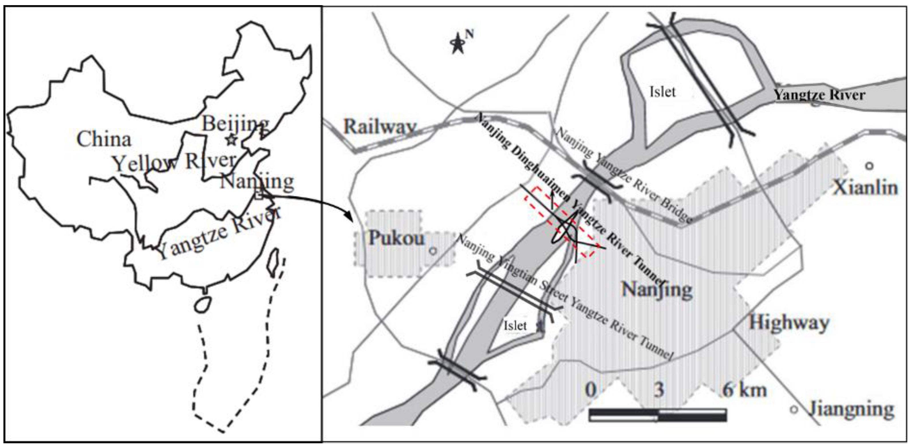
2.1. Project Site
2.2. Geological Conditions
3. Materials and Experimental Methods
3.1. Materials
3.2. Test Program
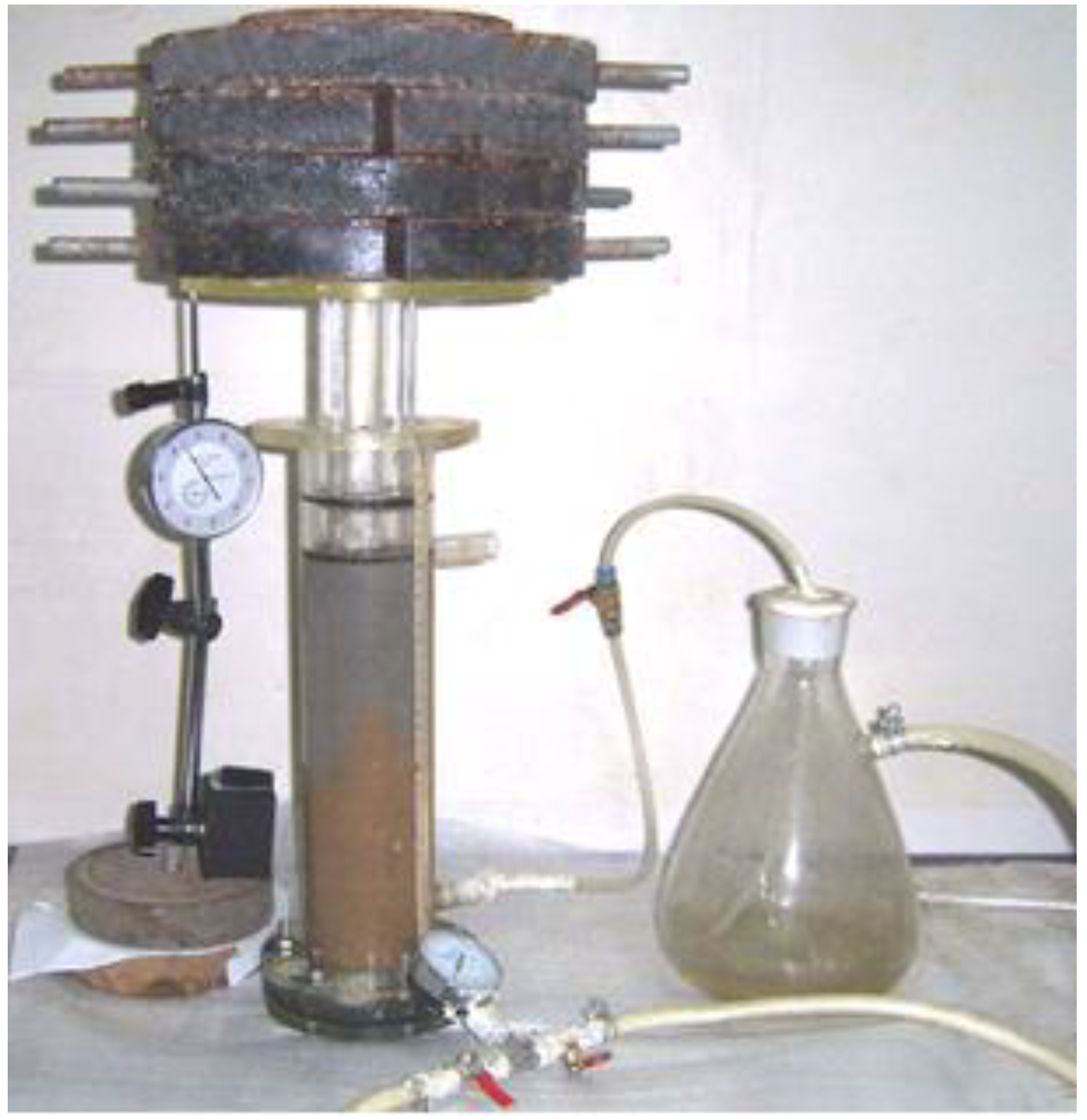
3.3. Test Methods
4. Results
4.1. Changes in Grout Properties
4.2. Selection of Grout Formula
5. Discussion
5.1. Influence of Fineness Modulus
5.2. Influence of Grain Size Distribution
5.3. Economic Analysis and Environmental Benefits
6. Conclusions
- (1)
- The engineering performance of the shield synchronous grouting material in which 75% of the sand in the original formula was replaced by excavated fine-silty sand screened through a 1.25 mm sieve, and in which the water/binder ratio was adjusted to 0.8, is close to or slightly higher than that of the original formula. Hence, it can be used in the recycling scheme.
- (2)
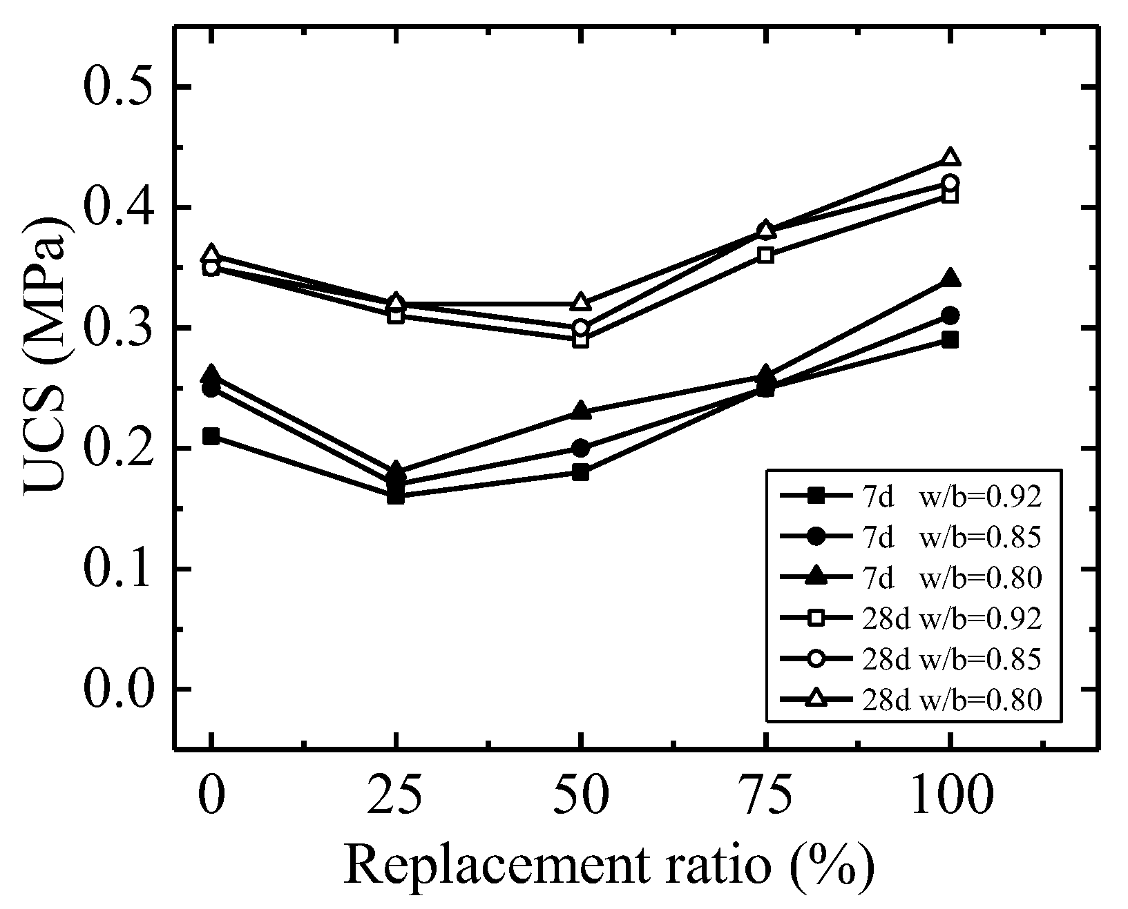
- As the replacement ratio increases, the grout’s density, fluidity, consistency, and bleeding rate gradually increase; meanwhile, the volumetric shrinkage increases initially before decreasing; the setting time decreases gradually
- (3)
- The sand used in the original formula was fine sand with a small fineness modulus and uniform particle size. At a mixing amount of <50%, a small change in the grain size distribution does not affect the engineering performance of the shield synchronous grouting material. However, the fineness modulus is the main influencing factor. At mixing amounts >50%, the grain size distribution changes greatly and has a leading influence on the shield synchronous grouting material’s performance.
- (4)
- Recycling the excavated silty-fine sand as shield synchronous grouting material can not only greatly reduce engineering costs but also significantly reduce environmental pollution, thereby promoting sustainable development.
Author Contributions
Funding
Institutional Review Board Statement
Informed Consent Statement
Data Availability Statement
Acknowledgments
Conflicts of Interest
References
- Wang, R.; Xu, H.; Liu, Y.; Jiang, P.; Zhou, A.; Lv, Y. Study on the shear strength characteristics and source mechanism of early-age shield synchronous grouting materials. Acta Geotech. 2023. [Google Scholar] [CrossRef]
- Geng, Z.; Jin, D.; Yuan, D. Face stability analysis of cohesion-frictional soils considering the soil arch effect and the instability failure process. Comput. Geotech. 2023, 153, 105050. [Google Scholar] [CrossRef]
- Feng, K.; He, C.; Qiu, Y.; Zhang, L.; Wang, W.; Xie, H.; Zhang, Y.; Cao, S. Full-scale tests on bending behavior of segmental joints for large underwater shield tunnels. Tunn. Undergr. Space Technol. 2018, 75, 100–116. [Google Scholar] [CrossRef]
- Funasaki, T.; Izumi, Y.; Masuda, T.; Kanai, M. The Tokyo Bay Tunnel of the Tram-Tokyo Bay Highway. In Proceedings of the 7th International Offshore and Polar Engineering Conference Proceedings (ISOPE-97), Honolulu, HI, USA, 25–30 May 1997; pp. 6–15. [Google Scholar]
- Min, F.; Zhu, W.; Lin, C.; Guo, X. Opening the excavation chamber of the large-diameter size slurry shield: A case study in Nanjing Yangtze River Tunnel in China. Tunn. Undergr. Space Technol. 2015, 46, 18–27. [Google Scholar] [CrossRef]
- Morris, M.; Yang, M.W.W.; Tsang, C.K.; Hu, A.Y.M.; Shut, D.S.C. An overview of subsea tunnel engineering in Hong Kong. Proc. Inst. Civ. Eng.-Civ. Eng. 2016, 169, 9–15. [Google Scholar] [CrossRef]
- Min, F.; Du, J.; Zhang, N.; Chen, X.; Lv, H.; Liu, L.; Yu, C. Experimental study on property change of slurry and filter cake of slurry shield under seawater intrusion. Tunn. Undergr. Space Technol. 2019, 88, 290–299. [Google Scholar] [CrossRef]
- Jin, D.; Shen, Z.; Yuan, D. Effect of spatial variability on disc cutters failure during TBM tunneling in hard rock. Rock Mech. Rock Eng. 2020, 53, 4609–4621. [Google Scholar]
- Geng, Z.; Yuan, D.; Wang, D.; Zhao, Y.; Xie, T. Study on Longitudinal Stress Relaxation Effect and Reinforcement Technology of Segment Lining during Shield Docking. Appl. Sci. 2022, 12, 2831. [Google Scholar] [CrossRef]
- Min, F.; Song, H.; Zhang, N. Experimental study on fluid properties of slurry and its influence on slurry infiltration in sand stratum. Appl. Clay Sci. 2018, 161, 64–69. [Google Scholar] [CrossRef]
- Wang, D.; Min, F.; Lyu, H.; Chen, J.; Wang, B. Recycling waste sand from slurry shield tunneling: A sustainable filter aid for waste slurry dehydration. J. Clean. Prod. 2023, 383, 135387. [Google Scholar] [CrossRef]
- Liu, M.-B.; Liao, S.-M.; Shi, Z.-H.; Liu, H.-K.; Chen, L.-S. Analytical study and field investigation on the effects of clogging in slurry shield tunneling. Tunn. Undergr. Space Technol. 2023, 133, 104957. [Google Scholar] [CrossRef]
- Zhang, C.; Yang, J.; Fu, J.; Wang, S.; Yin, J.; Xie, Y. Recycling of discharged soil from EPB shield tunnels as a sustainable raw material for synchronous grouting. J. Clean. Prod. 2020, 268, 121947. [Google Scholar] [CrossRef]
- Wang, J.; Cai, Y.; Ni, J.; Geng, X.; Xu, F. Effect of sand on the vacuum consolidation of dredged slurry. Mar. Georesour. Geotechnol. 2018, 36, 238–244. [Google Scholar] [CrossRef]
- Ooishi, Y.; Murakawa, S.; Hatakoshi, A.; Mori, T. Development of discharged soil measuring device for shield tunneling machines. J. Terramech. 1992, 29, 465–475. [Google Scholar] [CrossRef]
- Song, W.; Zhu, Z.; Pu, S.; Wan, Y.; Huo, W.; Song, S.; Hu, L. Synthesis and characterization of eco-friendly alkali-activated industrial solid waste-based two-component backfilling grouts for shield tunnelling. J. Clean. Prod. 2020, 266, 121974. [Google Scholar] [CrossRef]
- Zhang, C.; Chen, K.; Yang, J.; Fu, J.; Wang, S.; Xie, Y. Reuse of Discharged Soil from Slurry Shield Tunnel Construction as Synchronous Grouting Material. J. Constr. Eng. Manag. 2022, 148, 04021193. [Google Scholar] [CrossRef]
- Koyama, Y.; Okano, N.; Sato, Y.; Shimizu, M. Back-fill grouting model test for shield tunnel. Railw. Tech. Res. Inst. Q. Rep. 1998, 39, 35–39. [Google Scholar]
- Peila, D.; Borio, L.; Pelizza, S. The behaviour of a two-component back-filling grout used in a tunnel-boring machine. Acta Geotech. Slov. 2011, 8, 5–15. [Google Scholar]
- Bezuijen, A.; Talmon, A.; Kaalberg, F.; Plugge, R. Field Measurements of Grout Pressures During Tunnelling of the Sophia Rail Tunnel. Soils Found. 2004, 44, 39–48. [Google Scholar] [CrossRef]
- Talmon, A.; Bezuijen, A. Simulating the consolidation of TBM grout at Noordplaspolder. Tunn. Undergr. Space Technol. 2009, 24, 493–499. [Google Scholar] [CrossRef]
- Zhang, S.S.; Dai, Z.; Bai, Y. Research on the dissipation law of grout pressure during the simultaneous grouting of shield tunnel. China Railw. Sci. 2012, 33, 40–48. [Google Scholar]
- Liang, Y.; Yang, J.S.; Wang, S.Y.; Zeng, X.Y. A study on grout consolidation and dissipation mechanism during shield backfilled grouting with considering time effect. Rock Soil Mech. 2015, 36, 3373–3380. [Google Scholar]
- Zhou, S.; Li, X.; Ji, C.; Xiao, J. Back-fill grout experimental test for discharged soils reuse of the large-diameter size slurry shield tunnel. KSCE J. Civ. Eng. 2017, 21, 725–733. [Google Scholar] [CrossRef]
- Zhang, J.; Lu, S.; Feng, T.; Yi, B.; Liu, J. Research on reuse of silty fine sand in backfill grouting material and optimization of backfill grouting material proportions. Tunn. Undergr. Space Technol. 2022, 130, 104751. [Google Scholar] [CrossRef]
- Cui, Y.; Tan, Z. Experimental Study of High Performance Synchronous Grouting Materials Prepared with Clay. Materials 2021, 14, 1362. [Google Scholar] [CrossRef] [PubMed]
- Lim, S.K.; Tan, C.S.; Chen, K.P.; Lee, M.L.; Lee, W.P. Effect of different sand grading on strength properties of cement grout. Constr. Build. Mater. 2013, 38, 348–355. [Google Scholar] [CrossRef]
- De Schutter, G.; Poppe, A.-M. Quantification of the water demand of sand in mortar. Constr. Build. Mater. 2004, 18, 517–521. [Google Scholar] [CrossRef]
- Haach, V.G.; Vasconcelos, G.; Lourenço, P.B. Influence of aggregates grading and water/cement ratio in workability and hardened properties of mortars. Constr. Build. Mater. 2011, 25, 2980–2987. [Google Scholar] [CrossRef]
- Westerholm, M.; Lagerblad, B.; Silfwerbrand, J.; Forssberg, E. Influence of fine aggregate characteristics on the rheological properties of mortars. Cem. Concr. Compos. 2008, 30, 274–282. [Google Scholar] [CrossRef]
- Farhangi, V.; Karakouzian, M.; Geertsema, M. Effect of Micropiles on Clean Sand Liquefaction Risk Based on CPT and SPT. Appl. Sci. 2020, 10, 3111. [Google Scholar] [CrossRef]
- Roshani, M.; Kargar, S.; Farhangi, V.; Karakouzian, M. Predicting the Effect of Fly Ash on Concrete’s Mechanical Properties by ANN. Sustainability 2021, 13, 1469. [Google Scholar] [CrossRef]
- GB/T 2419-2005; Test Method for Fluidity of Cement Mortar. General Administration of Quality Supervision. Inspection and Quarantine of the People’s Republic of China: Beijing, China, 2005.
- JGJ/T 70-2009; Standard for Test Method of Performance on Building Mortar. Ministry of Housing and Urban-Rural Development of the People’s Republic of China: Beijing, China, 2009.
- GB/T 50080-2016; Standard for Test Method of Performance on Ordinary Fresh Concrete. General Administration of Quality Supervision. Inspection and Quarantine of the People’s Republic of China: Beijing, China, 2016.
- Liu, W.; Yan, S.; He, S. Landslide damage incurred to buildings: A case study of Shenzhen landslide. Eng. Geol. 2018, 247, 69–83. [Google Scholar] [CrossRef]


| Soil Stratum | Muddy-Silty Clay | Muddy-Silty Clay and Silty-Fine Sand | Silty-Fine Sand | Silty-Fine Sand, Gravel Sand, and Pebbles | Gravel Sand and Pebbles | Gravelly Sand, Pebbles, and Moderately Weathered Sandstone |
|---|---|---|---|---|---|---|
| Length | 870 | 345 | 1670 | 330 | 380 | 540 |
| Chemical | SiO2 | Al2O3 | Fe2O3 | CaO | MgO | SO3 |
|---|---|---|---|---|---|---|
| Cement | 21.50 | 5.80 | 2.70 | 63.00 | 2.09 | 3.55 |
| Fly ash | 52.70 | 30.50 | 4.32 | 6.38 | 1.46 | 0.72 |
| Bentonite | 70.76 | 14.93 | 1.89 | 0.96 | 1.77 | - |
| Requirement of Normal Consistency (%) | Setting Time (h:min) | Flexural Strength (28 Days; MPa) | Compressive Strength (28 Days; MPa) | |
|---|---|---|---|---|
| Initial Setting Time | Final Setting Time | |||
| 25.0 | 2:35 | 3:50 | 8.1 | 38.4 |
| Fineness | 45 μm Sieve Residue | Loss on Ignition (%) | Water Demand Ratio (%) |
|---|---|---|---|
| 25.6 | 14.6 | 1.53 | 101 |
| Pulverized Limestone | Fly Ash | Sand | Bentonite | Water Reducer | Water |
|---|---|---|---|---|---|
| 60.0 | 390.0 | 950.0 | 120.0 | 4.0 | 417.0 |
| No. | Replacement Ratio | Water–Binder Ratio | Fineness Modulus | Test Item |
|---|---|---|---|---|
| A1 A2 A3 | 0 | 0.92 | 0.781 | Density; Consistency (0 h, 3 h); Setting time; Fluidity (0 h, 3 h); Bleeding rate; Volume shrinkage (under 0.3 MPa); Unconfined compressive strength (days 7, 28). |
| 0.85 | ||||
| 0.80 | ||||
| B1 B2 B3 | 0.25 | 0.92 | 1.046 | |
| 0.85 | ||||
| 0.80 | ||||
| C1 C2 C3 | 0.50 | 0.92 | 1.210 | |
| 0.85 | ||||
| 0.80 | ||||
| D1 D2 D3 | 0.75 | 0.92 | 1.372 | |
| 0.85 | ||||
| 0.80 | ||||
| E1 E2 E3 | 1.00 | 0.92 | 1.652 | |
| 0.85 | ||||
| 0.80 |
| No. | Density (g/cm3) | Consistency (cm) | Fluidity (cm) | Bleeding Rate (%) | Setting Time (h) | Volume Shrinkage (%) | UCS (MPa) | |||
|---|---|---|---|---|---|---|---|---|---|---|
| Initial | 3 h | Initial | 3 h | 7 Days | 28 Days | |||||
| A1 | 1.92 | 11.0 | 9.4 | 21.2 | 18.7 | 1.7 | 62.5 | 16.5 | 0.21 | 0.35 |
| D1 | 1.96 | 13.1 | 11.7 | 26.3 | 21.7 | 3.6 | 52.0 | 17.2 | 0.25 | 0.36 |
| D2 | 1.96 | 12.6 | 10.7 | 25.2 | 20.0 | 3.6 | 49.0 | 16.1 | 0.25 | 0.38 |
| D3 | 1.97 | 12.2 | 10.1 | 23.8 | 18.9 | 3.0 | 45.5 | 14.8 | 0.26 | 0.38 |
| Sample | Fineness Modulus | Cu | Cc |
|---|---|---|---|
| A | 0.781 | 1.817 | 0.90 |
| B | 1.046 | 1.961 | 0.91 |
| C | 1.210 | 2.352 | 0.85 |
| D | 1.372 | 3.263 | 0.73 |
| E | 1.652 | 3.853 | 0.86 |
Disclaimer/Publisher’s Note: The statements, opinions and data contained in all publications are solely those of the individual author(s) and contributor(s) and not of MDPI and/or the editor(s). MDPI and/or the editor(s) disclaim responsibility for any injury to people or property resulting from any ideas, methods, instructions or products referred to in the content. |
© 2023 by the authors. Licensee MDPI, Basel, Switzerland. This article is an open access article distributed under the terms and conditions of the Creative Commons Attribution (CC BY) license (https://creativecommons.org/licenses/by/4.0/).
Share and Cite
Wang, R.; Xu, H.; Liu, Y.; Jiang, P.; Zhou, A. Reusing Fine Silty Sand Excavated from Slurry Shield Tunnels as a Sustainable Raw Material for Synchronous Grouting. Coatings 2023, 13, 398. https://doi.org/10.3390/coatings13020398
Wang R, Xu H, Liu Y, Jiang P, Zhou A. Reusing Fine Silty Sand Excavated from Slurry Shield Tunnels as a Sustainable Raw Material for Synchronous Grouting. Coatings. 2023; 13(2):398. https://doi.org/10.3390/coatings13020398
Chicago/Turabian StyleWang, Rui, Haoqing Xu, Yi Liu, Pengming Jiang, and Aizhao Zhou. 2023. "Reusing Fine Silty Sand Excavated from Slurry Shield Tunnels as a Sustainable Raw Material for Synchronous Grouting" Coatings 13, no. 2: 398. https://doi.org/10.3390/coatings13020398