Article

Cracking Behavior of Atmospheric Plasma-Sprayed 8YSZ Thermal Barrier Coatings during Thermal Shock Test

1
School of Materials Science and Engineering, South China University of Technology, Guangzhou 510640, China
2
Guangzhou Institute of Hubei Chaozhuo Aviation Technology Co., Ltd., Guangzhou 510530, China
3
Center for Industrial Analysis and Testing, Guangdong Academy of Sciences, Guangzhou 510650, China
*
Author to whom correspondence should be addressed.
Coatings 2023, 13(2), 243; https://doi.org/10.3390/coatings13020243
Submission received: 30 December 2022 / Revised: 16 January 2023 / Accepted: 18 January 2023 / Published: 20 January 2023
(This article belongs to the Special Issue Advanced Cold Spraying Technology)

Abstract

:
The failure of plasma-sprayed thermal barrier coatings (TBCs) during service is usually related to the cracking behavior. In this study, plasma-sprayed TBCs were prepared with two kinds of agglomerated sintered yttria-stabilized zirconia (YSZ) powders with different particle sizes. The evolution of mechanical properties and crack propagation behavior of the coatings during the whole life stage were studied by a thermal shock test. The effect of powder particle size on the cracking behavior of the TBCs during thermal shock was analyzed from the aspect of pore structure, mechanical properties, and stress state of the coatings. The crack propagation and coalescence in the direction parallel to the substrate in the coating is the main factor leading to the spalling failure of the coating during thermal shock. Although the coating prepared by fine YSZ has higher fracture toughness, the lower strain tolerance will increase the cracking driving force on the crack tip of the coating during thermal shock, and the cracks in the coating propagate merge at a faster rate during thermal shock. The larger porosity and pore size of the coating prepared by coarse YSZ help the coating suffer less thermal stress during thermal shock. Although the existence of pores reduces the fracture toughness of the coating to a certain extent, the increase of strain tolerance reduces the crack growth rate in the coating, so the coating has a longer life.

Graphical Abstract

1. Introduction

Thermal spraying coatings are often used to strengthen the surface of key components in aerospace, petrochemical and metallurgical fields to enhance their high temperature performance, wear and corrosion resistance [1,2,3,4]. Plasma-sprayed yttria-stabilized zirconia (YSZ) thermal barrier coating (TBCs) is a kind of functional coating which is widely used in thermal protection and thermal insulation of hot-end parts of gas turbine and aero-engine. The application of TBCs can improve the working temperature of the engine, thus improving the efficiency and performance [5,6]. Although the TBC technology has been successfully applied in gas turbine and aero-engine for many years, the coating still faces the risk of failure in a harsh service environment [7,8]. Once the coating peels off prematurely, the alloy protected by it will be directly exposed to excessive temperature, which poses a hidden danger and threat to the safety and reliability of the whole engine [9]. The failure of the TBCs during service is usually related to the cracking behavior of the coatings [10,11,12]. Therefore, the study of crack propagation behavior of the coatings is helpful to understand the failure mechanism of coatings and guide the development of new TBCs with long life.
The service process of TBCs is often accompanied by thermal shocks. Under the action of thermal stress, the coating is prone to crack near the TC/TGO/BC interface, resulting in the spalling of the ceramic layer and the failure of the coating [11,13,14]. The cracking resistance of the coating is very important to maintain the structural integrity of the coating during service, so in the development and preparation process of the TBCs, it is necessary to improve the fracture toughness of the ceramic layer so as to strengthen the resistance to interlayer cracking of the coating [15,16,17]. The feedstock powder morphology is an important parameter affecting the properties of TBCs. The powder size affects the deposition, solidification, and crystallization of molten droplets by influencing the particle state in the plasma, thus affecting the pore structure and mechanical properties of the coating [18,19]. Dwivedi et al. [19] studied the effect of the particle size of YSZ powder on the fracture toughness of plasma-sprayed coatings. Their results show that the fracture toughness of the coating decreases with the increase in powder size. The coating prepared with fine particle size powder has dense microstructure, low porosity and high fracture toughness. In addition to the cracking resistance, the pore structure of the coating is also an important factor affecting the cracking behavior of TBCs during thermal shock service [20,21,22]. The microstructure of plasma-sprayed coating contains a variety of pores, such as unbonded defects, macropores and microcracks [23,24]. The pores in the coating can reduce the thermal conductivity, increase the strain tolerance of the coating, and reduce the thermal stress during service, thus affecting the cracking behavior of the coating [20,25,26].
The cracking failure of plasma-sprayed TBCs under thermal shock largely depends on the joint action of cracking resistance and cracking driving force of the coatings [27]. The selection of particle size of sprayed powder is an important step in the TBC preparation process. Previous studies have shown that the coatings prepared by fine YSZ powder have denser structure and higher fracture toughness because of more sufficient melting of the fine powder during plasma-spraying [18]. However, on the other hand, increasing the strain tolerance of the coating with a porous structure is also very important to improve the thermal shock cracking resistance of the TBCs [28,29]. Up to now, it is still not very clear how the particle size of the powder responds to the cracking and failure behavior of the coating during thermal shock. In this study, plasma-sprayed TBCs were prepared with two kinds of agglomerated sintered YSZ powders with particle sizes of 5–45 μm and 15–70 μm. The evolution of mechanical properties and crack propagation behavior of the coatings in the whole life stage were studied by thermal shock experiments. The effect of powder particle size on the cracking failure behavior of the coating during thermal shock was analyzed from the point of view of pore structure, mechanical properties and stress state.

2. Materials and Methods

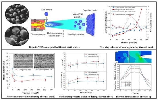
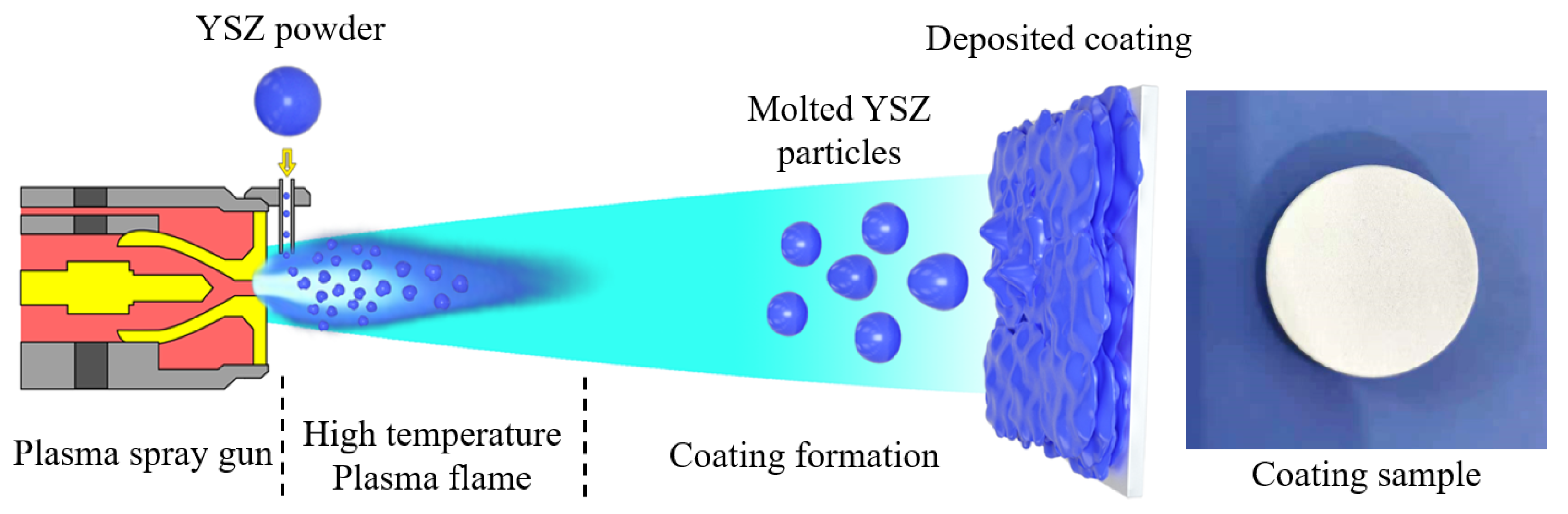
2.1. Coating Preparation

The TBCs samples were made of disc-shaped nickel-base alloy (IN-738) with thickness of 3 mm and diameter of 25.4 mm as substrate. Before spraying the coating, the surface of the substrate was treated by sandblasting and ultrasonic cleaning with acetone. The metal bonding layer coating and the ceramic top coat were deposited successively on the prepared substrate surface by atmospheric plasma-spraying (APS) process. The bond coat was prepared by NiCrAlY powder with a particle size of 5–70 μm. The ceramic coatings were sprayed with two kinds of 8YSZ (8wt.% Y2O3 stabilized ZrO2) powders with different particle sizes, which are called fine and coarse powders, respectively. Two kinds of 8YSZ powders are obtained by screening the same batch of powders. The morphology and particle size distribution of the two kinds of YSZ powders are shown in Figure 1. It can be seen that the two kinds of powders show good sphericity. From the enlarged surface and section, it can be seen that the powders are formed by agglomeration and sintering of submicron particles. The particle size distribution range of fine powder measured by laser particle size analyzer is 5–45 μm, and D50 is about 25 μm. The measured distribution range of coarse particle size powder is 15–70 μm, and D50 is about 45 μm.
The YSZ ceramic coat and NiCrAlY bond coat of all samples were prepared by a commercial atmospheric plasma-spraying equipment (APS-2000, Beijing Aeronautical Manufacturing Technology Research Institute, Beijing, China). Figure 2 shows the Schematic diagram of the YSZ coating deposited by plasma-spraying process. In the process of spraying, argon was used as the primary gas to form the plasma flame arc, and hydrogen was used as the auxiliary gas. The pressure of the main gas and auxiliary gas was controlled at 0.4 and 0.25 MPa respectively. The primary gas flow was controlled in 47 L/min, and the spraying voltage was controlled by adjusting the flow rate of auxiliary hydrogen, so as to adjust the arc power. According to the difference of melting point of YSZ ceramic and NiCrAlY metal powder, the power of plasma-spray gun was controlled to 36 and 30 kW, and the spraying distance was controlled to 70 and 100 mm respectively when spraying ceramic coat and bond coat. The moving speed of the spray gun was maintained at 150 mm/s during the coating spraying process. The two kinds of YSZ powders were prepared under the same powder feeding conditions, argon was used as carrier gas was controlled at 9 L/min, and the rotational speed of powder feeder was controlled at 1.5 r/min. The thickness of the deposited coating was controlled by spraying times. All TBC samples were prepared into a ceramic coat with a thickness of 300 μm and a bond coat with a thickness of 150 μm.

2.2. Evaluation of Coating Properties and Characterizations

The thermal shock experiment adopted the assessment temperature of 1050 °C. Each thermal shock included holding in a muffle furnace for 30 min and rapid cooling in water at room temperature. After the cooled sample was dried, the next thermal cycle was continued, and the thermal shock process was repeated until the coating fails. To study the crack evolution behavior of the TBCs, the thermal shocked TBC sample to different life stages was used to investigate the crack propagation behavior of the coating in the whole life stage.
The cross-sectional structure of coatings was observed using a scanning electron microscope (SEM, ZEISS EVO MA15, Carl Zeiss SMT Ltd., Cambridge, UK) in the backscattered and secondary electron modes with an acceleration voltage of 20 kV. The pore information of the coating was obtained by measuring the statistical cross-section image of the coating by the image analysis software Image-J 1.50i (National Institutes of Health, USA, https://imagej.nih.gov/ij (accessed on 17 January 2023)). In the process of statistical cracks, the image of the coating structure was continuously taken along the cross-section of the coating under an optical microscope (OM, ZEISS Observer A1 m, Carl Zeiss SMT Ltd., Cambridge, UK) under a 100× magnification, and then the image is spliced into an image containing the continuous cross-section of the coating. The crack information in the coating was obtained by count the length and number of cracks on the coating cross-section. In order to avoid the influence of the crack caused by the edge effect on the statistical results of the internal crack information of the coating, only the cracks in the 12.7 mm region (about half the diameter of the coating sample) at the center of the cross-section of the coating were counted. The crack density of the coating was obtained by dividing the number of cracks by the statistical length 12.7 mm. The cracking behavior of coatings in the thermal cycling was obtained by characterizing cracks in the samples after different cycles of thermal cycles.
The phase analyses of the YSZ feedstocks and coatings before and after thermal cyclic testing were examined by X-ray diffraction (XRD, D/max2550VB/PC, RIGAKU, Tokyo, Japan) using filtered Cu Kα radiation at an accelerated voltage of 40 kV and a current of 100 mA. Diffraction angles were set in the range of 10° to 80° with a step width of 0.02°. The hardness and fracture toughness of the coatings prepared by two kinds of particle size YSZ at different life stages were measured by a Vickers indenter. The indentation load of 300 g was used to measure the hardness, and the holding time was set to 15 s. The fracture toughness of the coating was measured by the indentation method to determine the crack propagation length of the coating under the action of indentation and calculate the crack extension force (GC). To make the coating crack under the action of indentation, the indentation load used to measure the fracture toughness was 1000 g. According to the indentation morphology and the crack generated, the critical crack growth energy release rate GC was calculated according to the following formula [21,30]:
GC = 6.115 × 10⁻⁴·a2·P/c3
where a is the half-diagonal length of the indentation, c is the crack length from the center of the indentation, and P is the intention load.

3. Results and Discussion

3.1. Microstructure and Fracture Toughness of Coating

Figure 3 shows the microstructure and pore size distribution information of the as-sprayed coatings prepared by two kinds of YSZ powders. The coating prepared by coarse particle size powder has higher porosity than that prepared by fine particle size YSZ. In particular, there are a large number of large pores in the coating prepared by coarse particle size powder. The particle size of the powder affects the deposition, solidification, and crystallization of molten droplets during plasma-spraying process, thus affecting the microstructure of the coatings [31]. Fine YSZ powder typically results in good melting during deposition, which reduces the volume of inter-splats gaps and voids during coating formation. As a result, the coating prepared by fine YSZ powder has lower porosity and smaller pores than that prepared by coarse YSZ powder.
Figure 4 shows the change of porosity of the coating prepared by two kinds of particle size YSZ powder during thermal shock. With the increase of thermal shock cycles, the porosity of the two kinds of coatings decreased rapidly at first, and then tended to stabilize at a certain level. It is worth noting that the porosity of the coating prepared by coarse YSZ powder is always higher than that of the coating prepared by fine YSZ. Previous studies have reported that plasma-sprayed coatings will be significantly sintered within a few hours of thermal shock, resulting in a decrease in the porosity of the coatings [32,33]. The sintering rate of the coating is related to the size of the pores in the coating, in which the large pores are difficult to be healed by sintering [34,35,36]. From the microstructure of the coating, it can be seen that the pores in the coating prepared by fine YSZ powder are finer than those of coarse YSZ powder, so the coating is easier to be sintered. The coating prepared by coarse powder contains more pores of larger size, so the sintering degree of the coating is not as serious as that of fine powder, and the coating still has relatively high porosity after thermal shock.
Figure 5 shows the XRD patterns of two kinds of YSZ powders and corresponding coatings. From the diffraction angle of 27° to 33°, it can be seen that there is a small amount of monoclinic phase (m phase) in the original YSZ powders of both sizes. However, after the two kinds of powders are melted and solidified to form the coating during plasma-spraying, there is no monoclinic phase exist in the coating. The structure of zirconia in both coatings is tetragonal. Therefore, the particle size of YSZ powder does not affect the phase structure of the coating, and the influence of phase structure can be excluded in the subsequent analysis of the cracking behavior of the two kinds of coating.
Fracture toughness is very important to resist cracking damage of coatings during thermal shock. Coatings with high fracture toughness are usually desired in coating design and preparation. Figure 6 shows the change of fracture toughness of the coatings during thermal shock. The fracture toughness of the coating prepared by two kinds of YSZ powder both increases with the increase of thermal shock time, and the fracture toughness of the coating prepared by fine particle size YSZ is always higher than that of the coating prepared by coarse YSZ powder during thermal shock. The porosity is an important factor affecting the fracture toughness of the coating [19]. The difference of fracture toughness between the two kinds of coatings is caused by the pore structure of the coatings. Finer YSZ powder resulted in better melting, compaction, and thus a denser structure. Coatings produced using coarse YSZ powder resulted in unmelted particle population, and a high level of porosity, including large interlamellar separations. The existence of pores reduces the cohesive bonding strength of the splats in the coating. The porosity of the coating prepared by fine YSZ powder is lower than that prepared by coarse YSZ during the whole thermal shock process, so the coating with a denser structure has higher fracture toughness.

3.2. Thermal Shock Spalling Behavior of Coating

In the thermal shock test, with the increase of cycle times, the thermal stress produced during thermal shock leads to the formation and propagation of cracks in the coating, which is characterized by the spalling of the coating macroscopically. Figure 7 shows the changes of macroscopic morphology and spalling ratio of the coatings prepared by two kinds of particle size YSZ during thermal shock experiments. When the two kinds of coatings were subjected to about 400 thermal shocks, only a little spalling occurred at the edge of the samples. After that, the spalling area of the coating increases with the increase of thermal shock cycles. The coating prepared by fine YSZ exfoliated in a large area during 400–500 thermal shock, and the spalling rate increased rapidly, from about 10% to 70%, or even completely. In contrast, the spalling rate of the coating prepared by coarse YSZ still increased gently after 400 thermal shocks, and there was no sharp spalling of the coating. Peeling only occurred at the edge of the coating after 600 thermal shocks.

3.3. Cracking Behavior of Coating

Figure 8 shows the variation of average crack length and crack density with thermal shock cycles in the coatings prepared by two kinds of YSZ powders. In the early stage of thermal shock (less than 400 cycles), the crack length of the two coatings increases uniformly with the increase of thermal shock cycles. After 400 thermal shocks, the crack length in the coating prepared by fine YSZ powder increases rapidly, and the average crack length increases to more than 200 μm after 500 thermal shocks. From the cross-section of the coating, it can be found that there is a penetrating transverse crack in the ceramic layer above the bond coat in the coating. Corresponding to the rapid increase of crack length, the coating exfoliates rapidly in large area macroscopically. Similar results in previous research also shows that the crack in the plasma-sprayed TBCs will expand to about 200 μm in length at 80% of the whole life, and then the coating will peel off rapidly and lead to the failure [11]. The average crack length of the coating prepared by coarse YSZ powder was about 80 μm after 200 thermal shocks. During the subsequent thermal shock, the crack length in the coating did not increase obviously, and even after 600 thermal shocks, the average crack length in the coating was only about 100 μm. The penetrating long crack formed by crack merging was not observed in the cross-section of the coating. As a result, the coating did not peel off rapidly after 500 thermal shocks.
The evolution of crack density is similar to that found by Jordan et al. [11]. The crack density in the coating prepared by two kinds of YSZ changed little in the first 200 thermal shocks. With the increase of cycles, the crack density in the coating shows a saddle-shaped trend, especially the coating prepared by fine YSZ is more obvious. After 200 thermal shocks, the crack density in the coating prepared by fine YSZ increases rapidly with the increase of cycle times, and reaches the maximum at 320 thermal shocks. Since then, as the thermal shock cycle continues to increase, the crack density in the coating decreases gradually. However, the crack density of the coating prepared by coarse YSZ did not change significantly during the whole thermal shock process.
The change trend of crack density is related to the crack evolution behavior in the coating, and the crack propagation in the coating can be inferred from the change of crack density and length. In practice, cracks exist and propagate in a three-dimensional form in the coating. The crack observation and statistics were obtained from the two-dimensional image of the cross-section, so it is necessary to accurately interpret the actual crack evolution state of the specimen corresponding to the crack information in the two-dimensional section.
Figure 9 shows a schematic diagram of the crack evolution behavior in the coating during thermal shock, so as to understand the relationship between the crack behavior in the coating and the statistical crack density. Figure 9a indicates the initiation of No. 1, 2, 3 and 4 cracks in the coating at the early stage of thermal shock. The crack is disc-shaped and propagates in the shape of emission in the coating. Crack No. 1 of the four cracks in this stage is located on the cut and observed section of the specimen and is observed in the crack statistics, while cracks No. 2, 3 and 4 cannot be observed because they are not on the cutting line. With the increase of thermal shock cycle, the crack in the coating propagates, and the crack state after propagation is shown in Figure 9b. After the No.1 crack propagates, the crack length observed from the cutting section increases, which reflects that the crack length increases in the crack statistics. After the No. 2 and No. 3 cracks near the cutting section propagate, the crack range extends to the observed cross-section, which reflects the statistical result that the crack density increases. It should be noted that some of these cracks may have just extended to the observed cross-section, so the observed crack length is shorter, while the actual crack length in the coating is larger. In addition, some cracks (such as No. 4) may not be observed in the cutting section after propagation, so such cracks will not be counted. As the thermal shock cycle continues to increase, the cracks in the coating will further expand and merge, such as cracks No. 2 and No. 3 in Figure 9c. After the crack merges, the number of cracks observed in the cross-section decreases and long cracks appear.
Based on the above analysis, it can be known that the increase of crack density in the coating section during thermal shock reflects the rapid crack propagation in the coating or the initiation of new cracks near the cross-section. The decrease of crack density in the later stage of thermal shock reflects the coalescence of cracks in the coating. When a large number of cracks in the coating merge, the coating will peel off rapidly and fail.
In Figure 8, the crack density of the coating prepared by fine YSZ increases rapidly during 200–300 thermal shocks, indicating that the cracks in the coating propagate at a faster rate, and a large number of cracks are observed in the cross-section. In this process, the accelerated increase of crack length in the coating also reflects that the crack in the coating is in the stage of active propagation. The sharp decrease of crack density in the coating after 300 thermal shocks indicates that more and more cracks merge in the coating, and accordingly, the statistical crack length in the cross-section increases rapidly. From the statistical results of crack length distribution in the coating after thermal shock in Figure 10, it can be seen that not only the number of shorter cracks in the cross-section of the coating increased significantly after 320 thermal shocks, but also a large number of cracks with a length of more than 200 μm appeared in the coating. After 510 thermal shocks, the number of short cracks (<200 μm) in the coating decreased, but the number of long cracks increased significantly. At this time, there is a penetrating horizontal crack in the coating, so the coating peels off rapidly and fails. Therefore, 200 μm can be regarded as the critical crack length of thermal shock failure of the coating. When the length of a large number of cracks in the coating exceeds 200 μm, the cracks in the coating will merge, resulting in the rapid spalling of the coating in the form of instability.
The crack density and average length of the coating prepared by coarse YSZ powder did not change significantly after 300 thermal shocks, indicating that the crack initiation and propagation behavior in the coating is slow. The statistics of crack length distribution in Figure 11 confirmed that the coating did not form many long cracks after 330 and 480 thermal shocks, and the crack distribution in the coating was similar to that in the initial stage of thermal shock. These results show that the cracks in the coating prepared by fine YSZ powder undergo a process of rapid propagation and coalescence in about 500 thermal shocks, which leads to the failure of the coating. However, the crack length and number of the coating prepared by coarse YSZ are stable during the whole thermal shock process, and there is no rapid crack propagation and coalescence after 480 thermal shocks, so the coating shows a longer thermal shock life.

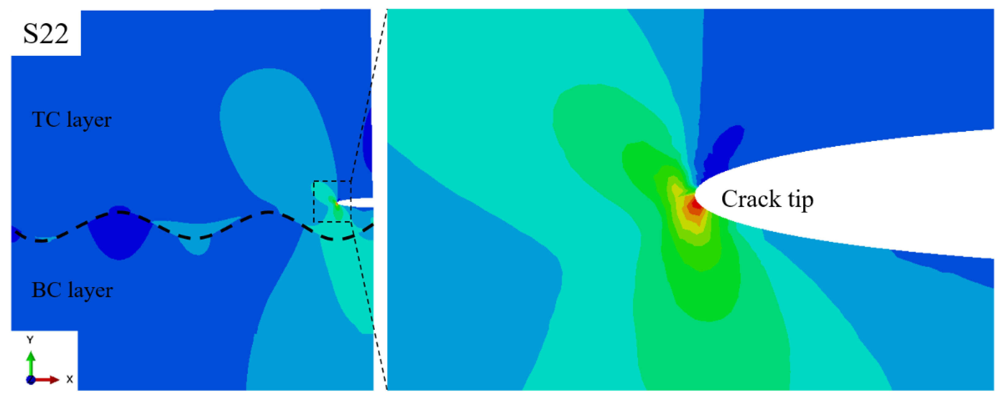
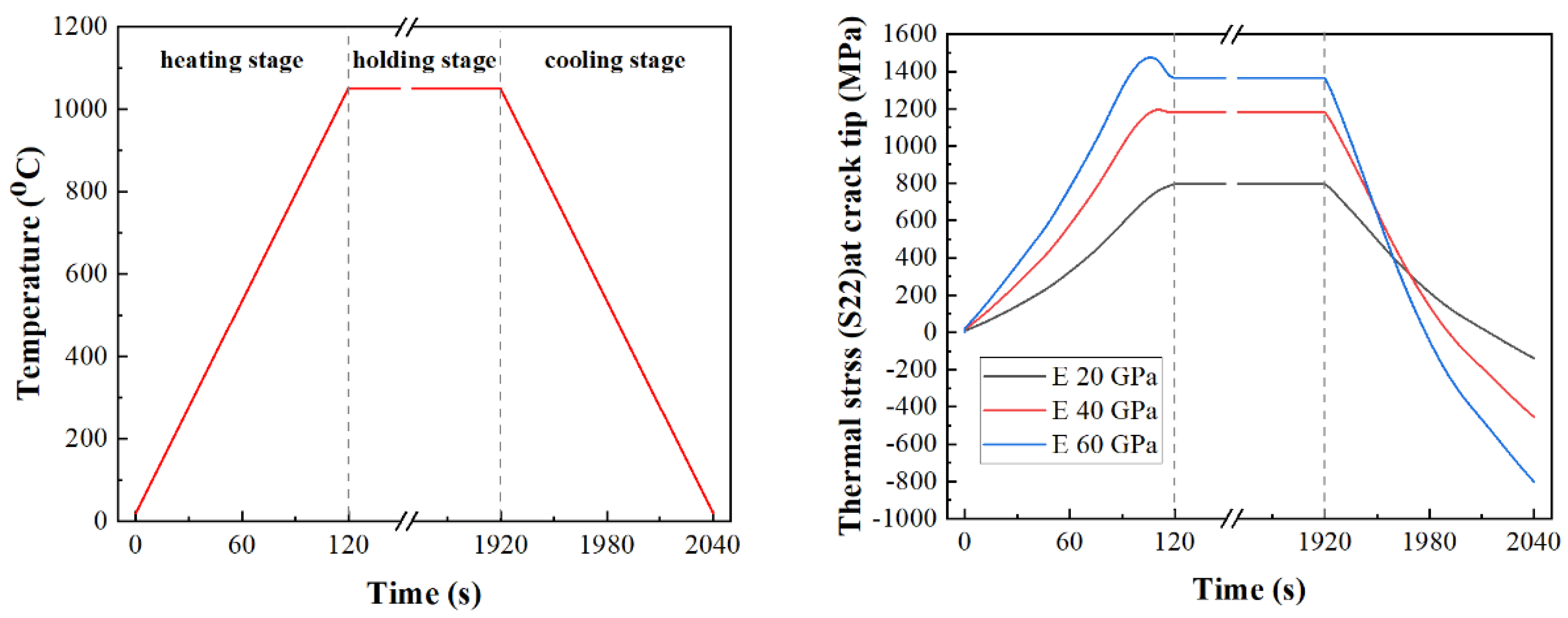
3.4. Effect of Strain Tolerance on Thermal Stress of Coating

Fracture toughness is a key factor affecting the cracking behavior of coatings. Before thermal shock experiments, according to the results of fracture toughness of two kinds of coatings, it is expected that the crack growth rate of the coating prepared with fine YSZ will be slower than that of the coating prepared with coarse YSZ, resulting in a longer thermal shock life. However, the thermal shock test results are contrary to the expectation, which shows that in addition to the fracture toughness, there are other factors that affect the cracking behavior of the coating.
In this study, the difference between the coatings prepared by the two kinds of YSZ powder is mainly reflected in the pore structure. Although the dense structure of the coating prepared by fine particle size YSZ powder has better fracture toughness, the decrease of porosity may also reduce the strain tolerance of the coating. The strain tolerance of the coating is also an important factor affecting the cracking behavior of TBCs during thermal shock conditions [26,28].
The hardness of the coating can reflect its strain tolerance. The higher the hardness of the coating is, the worse the strain tolerance is. During the thermal shock process, the hardness evolution of the coatings prepared by two kinds of particle size YSZ is shown in Figure 12. The hardness of the two kinds of coatings increased after thermal shock, and the hardness of the coating prepared by fine YSZ powder was higher than that of the coating prepared by coarse one during the whole thermal shock process. The hardness of the coating is related to its porosity. The literature has shown that the hardness and elastic modulus of the coating decrease with the increase of porosity [29,37]. In this study, the porosity of the coating prepared by coarse YSZ is higher than that of the coating prepared by fine particle size YSZ during the whole thermal shock process, so the coating has higher strain tolerance.
In addition to the anti-cracking ability of the coating itself, the thermal stress formed during thermal shock is also the key to affect the cracking behavior of the TBCs. Finite element simulation method was used to analyze the effect of the strain tolerance of the ceramic layer on the thermal stress at the crack tip of the coating.
Figure 13 shows the establishment of the finite element geometric model and the boundary conditions. The model was established according to the actual coating samples, including a Ni-based alloy substrate with a thickness of 3 mm, a bond coat layer with an average thickness of 150 μm and a top layer of YSZ ceramics with a thickness of 300 μm. A wavy interface similar to the actual shape was introduced between the bonding layer and the ceramic layer. From the cross-sectional morphology of the coating after thermal shock, it can be seen that the cracking leading to the spalling of the coating occurs in the ceramic layer within 100 μm above the interface between the bonding layer and the ceramic layer. According to the morphology of the crack in the coating (Figure 13a), a semi-elliptical crack was set up in the YSZ layer near the bond coat on the right side of the finite element model, and the thermal stress at the crack tip during thermal shock was investigated. The symmetrical boundary condition was adopted on the left side of the finite element model, the bottom boundary restricts the movement of the Y axis, and the upper boundary is set as a free boundary. Considering that the material below the right boundary crack is continuous, the multi-point constraint boundary condition (MPC) was adopted to make the boundary have the same displacement in the X-axis direction. Since there is a penetrating vertical crack in the upper part of the right boundary crack, it was set as a free boundary. The model includes nickel-based alloy matrix, NiCrAlY bonding layer and YSZ ceramic layer. The material property parameters of each layer used in the finite element simulation were taken from the literature [38,39], as shown in Table 1. To analyze the influence of the strain tolerance of the ceramic layer on the cracking of the coating, the elastic modulus of the YSZ layer is taken as a variable in the finite element simulation. The elastic modulus of 20, 40 and 60 GPa were selected to calculate the thermal stress of crack tip in the coating during thermal shock.
In the process of finite element simulation, a temperature load of simulating thermal shock was applied to the model to calculate the thermal stress caused by the thermal expansion mismatch of the coating. The temperature loading process includes heating the sample from room temperature (20 °C) to 1050 °C for 120 s, then holding 30 min at high temperature, and cooling to room temperature after 120 s. In the process of thermal shock, the cracking parallel to the interface direction of the bond coat/ceramic layer is the main reason for the spalling of the coating, so the stress S22 at the crack tip perpendicular to the cracking direction was paid more attention. Figure 14 shows the cloud diagram of the stress distribution of S22 in the coating at the end of the heating stage during the thermal shock process, which shows that there is an obvious stress concentration at the crack tip. The greater the stress there is, the greater the driving force of crack propagation is, the more serious the cracking in the coating will be.
The evolution of temperature and crack tip stress S22 of TBCs during the whole thermal shock process is shown in Figure 15. In the thermal shock heating stage, the stress at the crack tip increases with the increase of the sample temperature, and the maximum stress appears at the end of the heating stage. The stress in this process is a tensile stress perpendicular to the direction of crack propagation. The magnitude of the stress is an important factor driving the crack propagation. The elastic modulus of the ceramic layer has a significant effect on the stress level at the crack tip. When the elastic modulus increases from 20 GPa to 40 GPa and 60 GPa, the maximum stress S22 at the crack tip increases from 800 MPa to 1200 MPa and 1480 MPa, respectively.
In this simulation, the stress state of the coating during thermal shock was studied by elastic-plastic analysis, and the effect of elastic modulus of ceramic layer on the crack tip stress of the coating was investigated. The results show that reducing the elastic modulus of the ceramic coating plays a very significant role in alleviating the crack driving force in the coating. From the difference of porosity and hardness, it can be seen that the coating prepared by coarse particle size YSZ has lower elastic modulus than the coating prepared by fine particle size YSZ, so the coating bears less thermal stress at the crack tip during thermal shock.

3.5. Thermal Shock Resistant Analysis of Coating

The cracking behavior of TBCs during thermal shock depends on two factors; the cracking resistance of the coating itself and the cracking driving force formed during thermal shock. The porosity of the coating will affect its fracture toughness and strain tolerance. With the change of porosity, the fracture toughness and strain tolerance often change in the opposite direction, that is, when the fracture toughness of the coating increases by reducing the porosity, the strain tolerance of the coating will become worse. Considering the crack evolution behavior, porosity and mechanical properties of the coating during thermal shock, the effect of YSZ powder particle size on the thermal shock failure of the two coatings can be clarified. Although the porosity of the coating prepared by fine YSZ is small and the coating has relatively high fracture toughness, the strain tolerance of this coating is worse than that of the coating prepared by coarse YSZ. Therefore, the crack tip of the coating prepared by coarse YSZ is driven by greater cracking force during thermal shock. Since the adverse effect of the decrease of strain tolerance caused by low porosity of the coating prepared by fine YSZ is more significant than that on the improvement of fracture toughness of the coating, so the crack in the coating propagates at a faster rate during thermal shock, and the coating shows a shorter thermal shock life.
In addition, the pore size of the coating prepared by fine YSZ is smaller. These smaller pores are easier to be sintered at high temperature, resulting in a further reduction of the strain tolerance of the coating. Therefore, with the increase of thermal shock cycle, the cracking driving force of the crack tip in the coating becomes larger and larger. However, the pore size of the coating prepared by coarse YSZ is larger, and there are still many pores that cannot be sintered after thermal shock, which restrain the strain tolerance degradation of the coating to a certain extent. The study of Rad et al. [40] shows that the pores in the ceramic layer will significantly affect the stress distribution in the coating. The dispersed pores can alleviate stress concentration in the coating. In this experiment, the coating prepared by coarse YSZ powder was subjected to less thermal stress during thermal shock thanks to its higher porosity and larger pore size. Although the porosity reduces the fracture toughness of the coating to some extent, the increase of strain tolerance reduces the crack growth rate in the coating, so the coating prepared by coarse YSZ powder shows a longer thermal shock life.

4. Conclusions

The YSZ coatings with different microstructures were prepared by using two kinds of agglomerated sintered powders with particle sizes of 5–45 μm and 15–70 μm. The cracking failure behavior of the coatings during thermal shock was studied. The main conclusions are as follows:
(1) 
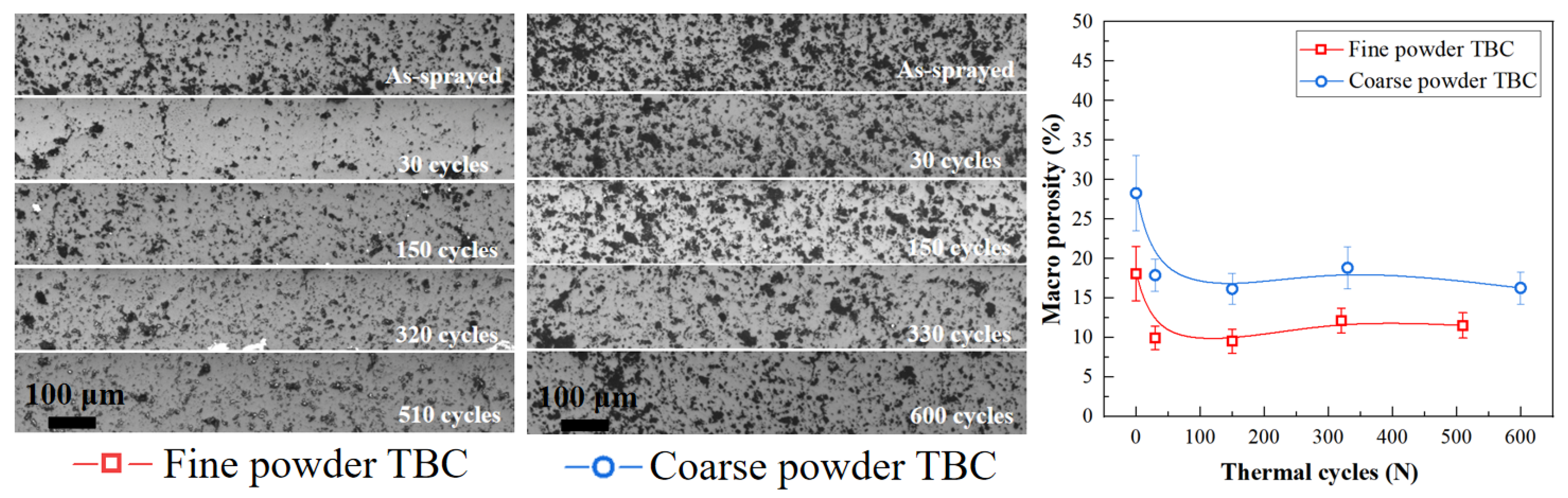
The effect of particle size of YSZ powder on the microstructure of the coating is mainly reflected in the porosity and pore size. The porosity of the coating prepared by fine powder is low, the pore size is small, and the small pores in the coating are easy to be sintered during thermal shock, which further reduces the porosity of the coating. The porosity and pore size of the coating prepared by coarse powder are relatively larger, the larger pores are difficult to be sintered after thermal shock, and the porosity of the coating is relatively high.
(2) 
The particle size of YSZ powder does not affect the phase structure of the atmospheric plasma-sprayed 8YSZ coating. The YSZ coatings prepared by coarse and fine particles are tetragonal zirconia.
(3) 
The particle size of the powder leads to the difference of the pore structure of the coating, which in turn affects the fracture toughness and strain tolerance of the coating. The change of porosity influences the fracture toughness and strain tolerance of the coating in opposite direction, that is, when the fracture toughness of the coating is increased by reducing the porosity, the strain tolerance of the coating will become worse. The coating prepared by fine powder has high fracture toughness because of its compact structure, but the strain tolerance of the coating is poor. Due to the existence of many pores, the fracture toughness of the coating prepared by coarse powder is relatively lower, but the strain tolerance of the coating is better.
(4) 
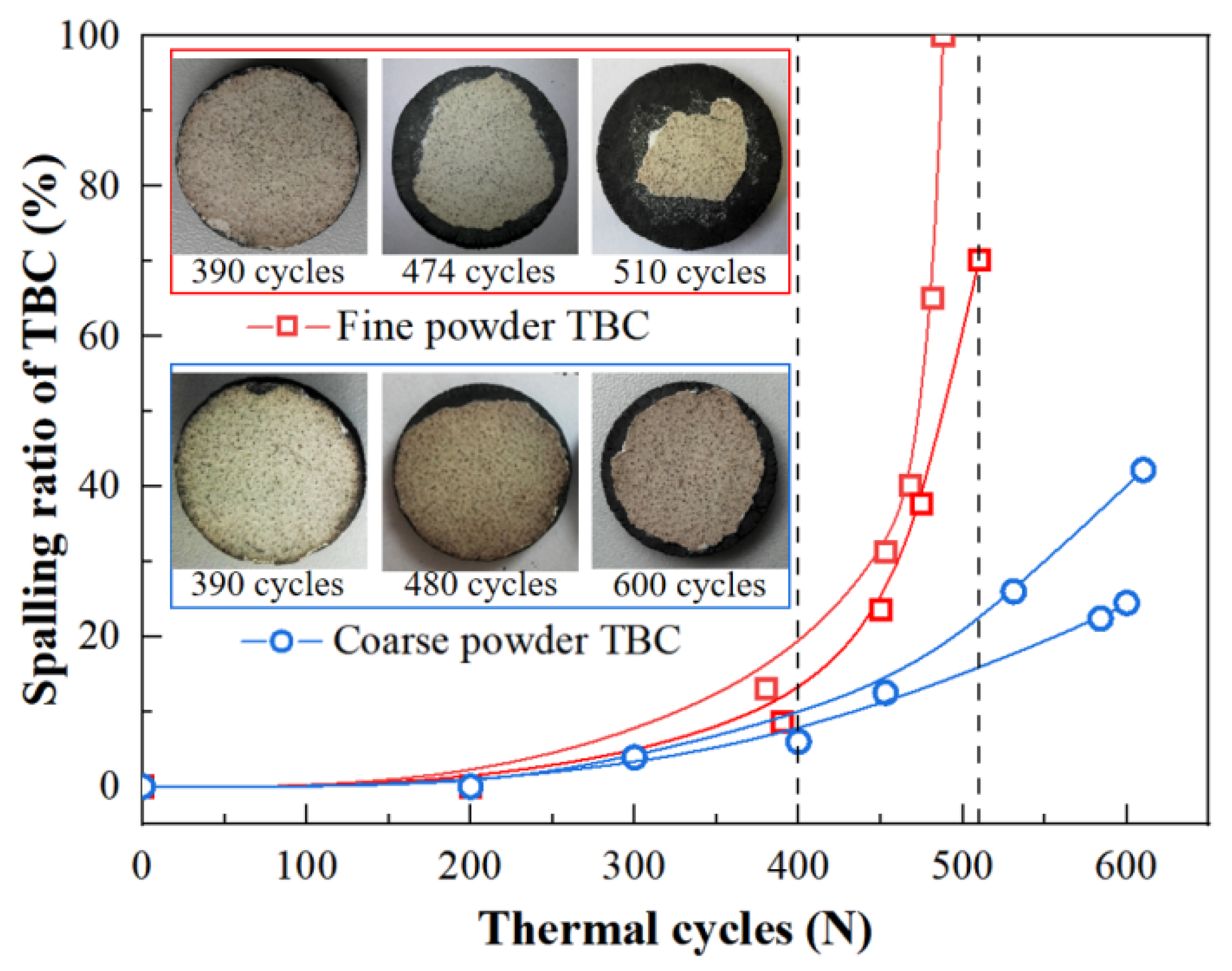
The fracture toughness and strain tolerance of the ceramic layer play an important role in the thermal shock life of the coating. Although the coating prepared by fine powder has relatively high fracture toughness, its lower strain tolerance will increase the cracking driving force on the crack tip of the coating during thermal shock. In the process of thermal shock, the cracks of the coating propagate and merge at a faster speed, and the thermal shock life is short. Although the larger porosity and pore size in the coating prepared by coarse particle size powder reduce the fracture toughness of the coating to a certain extent, the increase of sintering resistance and strain tolerance reduces the crack growth rate in the coating, and the coating has a longer life.
(5) 
The results of this study provide guidance for the development and design of high performance TBCs. When adjusting the pore structure of the coating, attention should be paid to the improvement of anti-cracking ability and strain tolerance at the same time.

Author Contributions

Formal analysis, J.H.; investigation, J.H.; resources, J.H.; data curation, W.S., R.H. and W.M.; writing—original draft preparation, J.H.; writing—review and editing, W.S., R.H. and W.M. All authors have read and agreed to the published version of the manuscript.

Funding

This work was supported by “the Fundamental Research Funds for the Central Universities, South China University of Technology”.

Institutional Review Board Statement

Not applicable.

Informed Consent Statement

Not applicable.

Data Availability Statement

All data that support the findings of this study are included within the article.

Conflicts of Interest

The authors declare no conflict of interest.

References

  1. Babu, P.S.; Madhavi, Y.; Krishna, L.R.; Sivakumar, G.; Rao, D.S.; Padmanabham, G. Thermal Spray Coatings for Erosion–Corrosion Resistant Applications. Trans. Indian Inst. Met. 2020, 73, 2141–2159. [Google Scholar] [CrossRef]
  2. Cinca, N.; Lima, C.R.C.; Guilemany, J.M. An overview of intermetallics research and application: Status of thermal spray coatings. J. Mater. Res. Technol. 2013, 2, 75–86. [Google Scholar] [CrossRef] [Green Version]
  3. Hardwicke, C.U.; Lau, Y.-C. Advances in thermal spray coatings for gas turbines and energy generation: A review. J. Therm. Spray Technol. 2013, 22, 564–576. [Google Scholar] [CrossRef] [Green Version]
  4. Paleu, C.C.; Munteanu, C.; Istrate, B.; Bhaumik, S.; Vizureanu, P.; Bălţatu, M.S.; Paleu, V. Microstructural Analysis and Tribological Behavior of AMDRY 1371 (Mo–NiCrFeBSiC) Atmospheric Plasma Spray Deposited Thin Coatings. Coatings 2020, 10, 1186. [Google Scholar] [CrossRef]
  5. Thakare, J.G.; Pandey, C.; Mahapatra, M.; Mulik, R.S. Thermal barrier coatings—A state of the art review. Met. Mater. Int. 2021, 27, 1947–1968. [Google Scholar] [CrossRef]
  6. Wee, S.; Do, J.; Kim, K.; Lee, C.; Seok, C.; Choi, B.-G.; Choi, Y.; Kim, W. Review on mechanical thermal properties of superalloys and thermal barrier coating used in gas turbines. Appl. Sci. 2020, 10, 5476. [Google Scholar] [CrossRef]
  7. Darolia, R. Thermal barrier coatings technology: Critical review, progress update, remaining challenges and prospects. Int. Mater. Rev. 2013, 58, 315–348. [Google Scholar] [CrossRef]
  8. Mehta, A.; Vasudev, H.; Singh, S.; Prakash, C.; Saxena, K.K.; Linul, E.; Buddhi, D.; Xu, J. Processing and Advancements in the development of thermal barrier coatings: A Review. Coatings 2022, 12, 1318. [Google Scholar] [CrossRef]
  9. Kumar, V.; Balasubramanian, K. Progress update on failure mechanisms of advanced thermal barrier coatings: A review. Prog. Org. Coat. 2016, 90, 54–82. [Google Scholar] [CrossRef]
  10. Song, D.; Song, T.; Paik, U.; Lyu, G.; Jung, Y.-G.; Choi, B.-G.; Kim, I.-S.; Zhang, J. Crack-growth behavior in thermal barrier coatings with cyclic thermal exposure. Coatings 2019, 9, 365. [Google Scholar] [CrossRef]
  11. Ahmadian, S.; Jordan, E.H. Explanation of the effect of rapid cycling on oxidation, rumpling, microcracking and lifetime of air plasma sprayed thermal barrier coatings. Surf. Coat. Technol. 2014, 244, 109–116. [Google Scholar] [CrossRef]
  12. Dong, H.; Yang, G.-J.; Cai, H.-N.; Li, C.-X.; Li, C.-J. Propagation feature of cracks in plasma-sprayed YSZ coatings under gradient thermal cycling. Ceram. Int. 2015, 41, 3481–3489. [Google Scholar] [CrossRef]
  13. Ahmadian, S.; Thistle, C.; Jordan, E.H.; Hsueh, C.H. Experimental and Finite Element Study of an Air Plasma Sprayed Thermal Barrier Coating under Fixed Cycle Duration at Various Temperatures. J. Am. Ceram. Soc. 2013, 96, 3210–3217. [Google Scholar] [CrossRef]
  14. Huang, J.; Wang, W.; Yu, J.; Wu, L.; Feng, Z. Effect of Particle Size on the Micro-cracking of Plasma-Sprayed YSZ Coatings During Thermal Cycle Testing. J. Therm. Spray Technol. 2017, 26, 755–763. [Google Scholar] [CrossRef]
  15. Viswanathan, V.; Dwivedi, G.; Sampath, S. Engineered Multilayer Thermal Barrier Coatings for Enhanced Durability and Functional Performance. J. Am. Ceram. Soc. 2014, 97, 2770–2778. [Google Scholar] [CrossRef]
  16. Viswanathan, V.; Dwivedi, G.; Sampath, S. Multilayer, multimaterial thermal barrier coating systems: Design, synthesis, and performance assessment. J. Am. Ceram. Soc. 2015, 98, 1769–1777. [Google Scholar] [CrossRef]
  17. Li, C.J.; Li, Y.; Yang, G.J.; Li, C.X. Evolution of Lamellar Interface Cracks During Isothermal Cyclic Test of Plasma-Sprayed 8YSZ Coating with a Columnar-Structured YSZ Interlayer. J. Therm. Spray Technol. 2013, 22, 1374–1382. [Google Scholar] [CrossRef]
  18. Huang, J.; Wang, W.; Lu, X.; Liu, S.; Li, C. Influence of lamellar interface morphology on cracking resistance of plasma-sprayed YSZ coatings. Coatings 2018, 8, 187. [Google Scholar] [CrossRef] [Green Version]
  19. Dwivedi, G.; Viswanathan, V.; Sampath, S.; Shyam, A.; Lara-Curzio, E. Fracture Toughness of Plasma-Sprayed Thermal Barrier Ceramics: Influence of Processing, Microstructure, and Thermal Aging. J. Am. Ceram. Soc. 2014, 97, 2736–2744. [Google Scholar] [CrossRef]
  20. Mauer, G.; Du, L.; Vaßen, R. Atmospheric Plasma Spraying of Single Phase Lanthanum Zirconate Thermal Barrier Coatings with Optimized Porosity. Coatings 2016, 6, 49. [Google Scholar] [CrossRef]
  21. Huang, J.B.; Wang, W.Z.; Li, Y.J.; Fang, H.J.; Ye, D.D.; Zhang, X.C.; Tu, S.T. A novel strategy to control the microstructure of plasma-sprayed YSZ thermal barrier coatings. Surf. Coat. Technol. 2020, 402, 126304. [Google Scholar] [CrossRef]
  22. Huang, J.B.; Wang, W.Z.; Li, Y.J.; Fang, H.J.; Ye, D.D.; Zhang, X.C.; Tu, S.T. Novel-structured plasma-sprayed thermal barrier coatings with low thermal conductivity, high sintering resistance and high durability—ScienceDirect. Ceram. Int. 2020, 47, 5156–5167. [Google Scholar] [CrossRef]
  23. Bakan, E.; Vaßen, R. Ceramic Top Coats of Plasma-Sprayed Thermal Barrier Coatings: Materials, Processes, and Properties. J. Therm. Spray Technol. 2017, 26, 992–1010. [Google Scholar] [CrossRef]
  24. Odhiambo, J.G.; Li, W.; Zhao, Y.; Li, C. Porosity and its significance in plasma-sprayed coatings. Coatings 2019, 9, 460. [Google Scholar] [CrossRef] [Green Version]
  25. Medřický, J.; Curry, N.; Pala, Z.; Vilemova, M.; Chraska, T.; Johansson, J.; Markocsan, N. Optimization of High Porosity Thermal Barrier Coatings Generated with a Porosity Former. J. Therm. Spray Technol. 2015, 24, 622–628. [Google Scholar] [CrossRef]
  26. Huang, J.; Wang, W.; Li, Y.; Fang, H.; Ye, D.; Zhang, X.; Tu, S. Improve durability of plasma-splayed thermal barrier coatings by decreasing sintering-induced stiffening in ceramic coatings. J. Eur. Ceram. Soc. 2019, 40, 1433–1442. [Google Scholar] [CrossRef]
  27. Cheng, B.; Yang, N.; Zhang, Q.; Zhang, Y.-M.; Chen, L.; Yang, G.-J.; Li, C.-X.; Li, C.-J. Sintering induced the failure behavior of dense vertically crack and lamellar structured TBCs with equivalent thermal insulation performance. Ceram. Int. 2017, 43, 15459–15465. [Google Scholar] [CrossRef]
  28. Zou, Z.; Xing, C.; He, L.; Shan, X.; Luo, L.; Zhao, X.; Guo, F.; Xiao, P. A Highly Strain and Damage Tolerant Thermal Barrier Coating Fabricated by Electro: Prayed Zirconia Hollow Spheres. J. Am. Ceram. Soc. 2018, 101, 4375–4386. [Google Scholar] [CrossRef]
  29. Bakan, E.; Mack, D.E.; Mauer, G.; Mücke, R.; Vaßen, R. Porosity–Property Relationships of Plasma-Sprayed Gd2Zr2O7/YSZ Thermal Barrier Coatings. J. Am. Ceram. Soc. 2015, 98, 2647–2654. [Google Scholar] [CrossRef]
  30. Lin, X.; Zeng, Y.; Lee, S.W.; Ding, C. Characterization of alumina–3 wt.% titania coating prepared by plasma spraying of nanostructured powders. J. Am. Ceram. Soc. 2004, 24, 627–634. [Google Scholar] [CrossRef]
  31. Huang, J.; Wang, W.; Lu, X.; Hu, D.; Feng, Z.; Guo, T. Effect of Particle Size on the Thermal Shock Resistance of Plasma-Sprayed YSZ Coatings. Coatings 2017, 7, 150. [Google Scholar] [CrossRef] [Green Version]
  32. Li, G.R.; Li, C.X.; Li, C.J.; Yang, G.J. Sintering characteristics of plasma-sprayed TBCs: Experimental analysis and an overall modelling. Ceram. Int. 2018, 44, 2982–2990. [Google Scholar] [CrossRef]
  33. Yan, J.; Wang, X.; Chen, K.; Lee, K.N. Sintering modeling of thermal barrier coatings at elevated temperatures: A review of recent advances. Coatings 2021, 11, 1214. [Google Scholar] [CrossRef]
  34. Markocsan, N.; Nylen, P.; Wigren, J.; Li, X.; Tricoire, A. Effect of thermal aging on microstructure and functional properties of zirconia-base thermal barrier coatings. J. Therm. Spray Technol. 2009, 18, 201–208. [Google Scholar] [CrossRef]
  35. Erdogan, G.; Ustel, F.; Bobzin, K.; Öte, M.; Linke, T.F.; Zhao, L. Influence of long time post annealing on thermal stability and thermophysical properties of plasma sprayed La2Zr2O7 coatings. J. Alloys Compd. 2017, 695, 2549–2555. [Google Scholar] [CrossRef]
  36. Liu, T.; Chen, X.; Yang, G.-J.; Li, C.-J. Properties evolution of plasma-sprayed La 2 Zr 2 O 7 coating induced by pore structure evolution during thermal exposure. Ceram. Int. 2016, 42, 15485–15492. [Google Scholar] [CrossRef]
  37. Nakamura, T.; Qian, G.; Berndt, C.C. Effects of Pores on Mechanical Properties of Plasma-Sprayed Ceramic Coatings. J. Am. Ceram. Soc. 2000, 83, 578–584. [Google Scholar] [CrossRef] [Green Version]
  38. Białas, M. Finite element analysis of stress distribution in thermal barrier coatings. Surf. Coat. Technol. 2008, 202, 6002–6010. [Google Scholar] [CrossRef]
  39. Jiang, J.; Xu, B.; Wang, W.; Adjei, R.A.; Zhao, X.; Liu, Y. Finite element analysis of the effects of thermally grown oxide thickness and interface asperity on the cracking behavior between the thermally grown oxide and the bond coat. J. Eng. Gas Turbines Power 2017, 139, 022504. [Google Scholar] [CrossRef]
  40. Rad, M.R.; Farrahi, G.; Azadi, M.; Ghodrati, M. Stress analysis of thermal barrier coating system subjected to out-of-phase thermo-mechanical loadings considering roughness and porosity effect. Surf. Coat. Technol. 2015, 262, 77–86. [Google Scholar]
Figure 1. Morphology and particle size distribution of the two kinds of YSZ powders: (a) fine powder; (b) coarse powder; (c) magnification of powder surface morphology; (d) magnification of powder cross-section morphology and (e) particle size distribution.
Coatings 13 00243 g001
Figure 2. Schematic diagram of the YSZ coating deposited by plasma-spraying process and images of the prepared coating samples.
Coatings 13 00243 g002
Figure 3. Typical microstructure and pore size distribution of the as-sprayed coatings prepared by the fine and coarse YSZ powder.
Coatings 13 00243 g003
Figure 4. Evolution of porosity of two kinds of coatings during thermal cycling test.
Coatings 13 00243 g004
Figure 5. XRD patterns of two kinds of YSZ powder and corresponding coating: (a) fine powder; (b) coarse powder.
Coatings 13 00243 g005
Figure 6. Evolution of fracture toughness of two kinds of coatings during thermal cycling test.
Coatings 13 00243 g006
Figure 7. Evolution of macroscopic morphology and spalling ratio of the two kinds of TBCs during thermal cycling.
Coatings 13 00243 g007
Figure 8. Evolution of crack length and density in the two kinds of coatings during thermal cycling test and typical crack morphology in coatings after thermal cycling.
Coatings 13 00243 g008
Figure 9. Schematic diagram of crack evolution behavior in the coating during thermal cycling: (a) crack initiation; (b) crack propagation and (c) crack coalescence.
Coatings 13 00243 g009
Figure 10. Distribution of crack length in the coating prepared by fine YSZ powder after different thermal cycles: (a) 90 cycles; (b) 150 cycles; (c) 320 cycles and (d) 510 cycles.
Coatings 13 00243 g010
Figure 11. Distribution of crack length in the coating prepared by coarse YSZ powder after different thermal cycles: (a) 90 cycles; (b) 150 cycles; (c) 330 cycles and (d) 480 cycles.
Coatings 13 00243 g011
Figure 12. Hardness evolution of two kinds of YSZ coatings during thermal cycling.
Coatings 13 00243 g012
Figure 13. The geometric model, boundary conditions and meshes of the finite element model. (a) SEM images of cracking characteristics in the coating; (b) simplified model extracted from coating structure and (c) mesh structure and boundary conditions of the finite element model.
Coatings 13 00243 g013
Figure 14. Stress (S22) distribution in coating at the end of heating stage during thermal cycling.
Coatings 13 00243 g014
Figure 15. Evolution of stress S22 at the crack tip in the coating during thermal cycling.
Coatings 13 00243 g015
Table 1. Temperature dependent physical properties of substrate, bond coat and YSZ topcoat.
MaterialsTemperature
(oC)
Elastic Modulus
(GPa)
Thermal Expansion Coefficient
(10−6 °C−1)
Poisson’s RatioYield Strength
(GPa)
Substrate20123120.36888
42010812.50.37887
8209214.70.38910
10208415.80.38470
BC2015212.30.32426
42014515.20.33396
82010916.30.35284
10207217.60.35150
YSZ202040609.70.2-
4202040609.70.2-
820204060100.2-
102020406010.40.2-
Disclaimer/Publisher’s Note: The statements, opinions and data contained in all publications are solely those of the individual author(s) and contributor(s) and not of MDPI and/or the editor(s). MDPI and/or the editor(s) disclaim responsibility for any injury to people or property resulting from any ideas, methods, instructions or products referred to in the content.

