Article

Structural Transition in the Growth of Copper Terephthalate Metal–Organic Frameworks: Understanding the Effect of the Synthetic Protocol and Its Impact on Electrochemical Behavior

by
Sara L. Rodríguez
1,
Gabriela A. Ortega-Moreno
1,
Manuel Sánchez-Sánchez
2,
José L. Fernández
3 and
Juan M. Zamaro
1,*
1
Instituto de Investigaciones en Catálisis y Petroquímica (INCAPE), Universidad Nacional del Litoral—CONICET, Santiago del Estero 2829, Santa Fe 3000, Argentina
2
Instituto de Catálisis y Petroleoquímica (ICP), CSIC, C/Marie Curie, 2, 28049 Madrid, Spain
3
Instituto de Química Aplicada del Litoral (IQAL) and Programa de Electroquímica Aplicada e Ingeniería Electroquímica (PRELINE), Universidad Nacional del Litoral—CONICET, Santiago del Estero 2829, Santa Fe 3000, Argentina
*
Author to whom correspondence should be addressed.
Coatings 2023, 13(12), 2065; https://doi.org/10.3390/coatings13122065
Submission received: 28 October 2023 / Revised: 25 November 2023 / Accepted: 7 December 2023 / Published: 10 December 2023
(This article belongs to the Special Issue Advanced Research on Energy Storage Materials and Devices)

Abstract

:
Some copper-based metal–organic frameworks show promise for use as electrocatalysts because they allow for an electrode configuration in which copper species with redox and electron-conducting properties are immobilized in a three-dimensional arrangement. This work shows that the synthesis of copper terephthalates (Cu-BDCs) can lead to rigid structures of the copper hydroxyterephthalate-type or flexible structures that are isoreticular to the MOF-2 type, depending solely on the synthesis route. Here, a detailed analysis of the syntheses of the crystals is carried out employing protocols with different solvents as well as conventional or microwave-assisted solvothermal methods. All solids were fully characterized by a combination of characterization techniques, such as FE-SEM, T-XRD, TGA, and FTIR, and their electrochemical redox responses were also evaluated by cyclic voltammetry. A correlation between the Cu-BDCs structures and their electrochemical behaviors was established and a new version of an electroactive copper hydroxyterephthalate was synthesized by a microwave method in 3 h with a dimethylformamide-free protocol. This Cu-BDC was obtained as dispersed nanoflakes with a high amount of copper sites and the capacity to be reversibly electroreduced-oxidized and showed catalytic activity in the oxygen reduction reaction (ORR).

1. Introduction

The sustainability of human society depends on the development of new renewable and clean energy systems [1,2,3]. Against this backdrop, electrochemistry offers green and efficient technological alternatives for energy storage and conversion, fuel production and environmental protection [1,2]. For example, the operation of batteries, fuel cells, electrolytic cells and supercapacitors is based on electrochemical half-reactions, such as the hydrogen evolution reaction (HER), the oxygen evolution reaction (OER), the hydrogen oxidation reaction (HOR), the oxygen reduction reaction (ORR) and the carbon dioxide reduction reaction (CO2RR) [2,4]. However, these half-reactions have very slow kinetics, which is why they require large overpotentials and excessive amounts of energy to be carried out, and in some cases obtain cell potentials and powers much lower than the theoretical values [1,4]. To overcome this barrier and improve the efficiency of current energy devices, the search for new electrocatalysts that are more economical, stable, efficient and capable of significantly promoting these electrochemical reactions is crucial [1,3,4,5]. A promising alternative are metalloenzymes such as cytochrome c oxidase and multicopper oxidases, which are capable of activating, reducing and transporting oxygen efficiently and selectively using multinuclear iron and/or copper complexes as active sites [6,7,8]. Considering the structural design of bio-electrocatalysts present in nature, different functional materials based on 3D transition metals have been explored as new electrocatalysts. Among these, metal–organic frameworks (MOFs) have begun to show increasing promise in the field of electrocatalysis [1,3,4,5].
MOFs are highly crystalline solids in whose structure multifunctional organic linkers and metallic centers are assembled, resulting in periodic nets with organic–inorganic nature and with permanent porosity [9]. MOFs are fascinating materials that have found application in several technological areas, such as selective separations [10], sensors [11] detection of biomarkers [12] and catalysis [13], among others. In particular, the use of MOFs as electrocatalysts has been spreading due to their unique nature which allows a high dispersion of metal centers with redox capacity that favor the transfer of electrons and ions between the surface of the electrodes and the electrolyte [1]. The remarkable design flexibility of MOFs, in addition to their possibility of functionalization and diversity of metal centers, has prompted the study of MOFs and MOF-derived materials as electrocatalysts for various reactions relevant in energy-conversion electrochemical technologies, such as the ORR, the OER, the CO2RR, water splitting, among others [1,2,3,4,5,14,15,16,17]. In particular, copper-based MOFs (Cu-MOFs) are currently being studied intensively as electrocatalysts for different electrochemical applications, such as the use of Cu-MOF-74 as an electrocatalyst for the ORR [14], Cu-tetrahydroxyquinone (Cu-THQ) as an electrocatalyst for the CO2RR [18] or Cu3(Cu3·HAHATN)2 as electrocatalyst for the HER [19]. Within the family of Cu-MOFs, copper terephthalates (Cu-BDCs) are of interest as they have wide structural diversity and have been little explored in electrocatalysis. These Cu-BDCs are polymorphic structures capable of adopting arrangements with chain-type (1D) or layer-type (2D) dimensionality.
Despite the chemical and structural richness that MOFs offer, their electrocatalytic use presents important challenges because the activity usually depends, among many other factors, on the accessibility of the active sites and on the electrical conductivity and geometry of the electrodes [20]. Although MOFs have abundant metal sites, a small fraction of them can be effectively used in electrocatalytic processes due to the poor electrical conductivity of these materials (~10−10 Sm−1) [1,20]. Furthermore, the nanometric pore size in some MOFs hinders an efficient transport of the electrolyte to the active sites, as well as the diffusion of products, impoverishing the electrode performance [1,20]. Faced with this problem, an alternative that could be useful is the application of structural engineering principles with which the exposed surface and morphology of the materials can be optimized (for example, seeking to direct the synthesis towards morphologies with highly dispersed and easily accessible active sites, such as nanoflakes), among other properties, to improve their electrochemical responses [5]. Microwave-assisted synthesis has proven to be a sustainable and economical method by which to carry out these structural modifications and optimizations [21,22]. In this context, this work aims to evaluate the relationship between the structure and electrochemical response of Cu-based MOFs and in particular how this is affected by the applied synthesis protocols. To this end copper terephthalate-type metal–organic frameworks were synthesized and characterized through a combination of techniques in order to then evaluate their electrochemical redox and electrocatalytic responses. These studies contribute to the rational modulation of the electrochemical properties of copper-based MOFs by establishing an understanding of the structure–behavior relationships.

2. Experimental

2.1. Chemical Reagents

The synthesis of Cu-BDCs was carried out using the following reagents and solvents: 1,4 benzenedicarboxylic acid (H2BDC, 98% purity, Sigma-Aldrich, Burlington, MA, USA), copper nitrate trihydrate (Cu(NO3)2·3H2O, Aldrich, 99–104% purity), N,N-dimethylformamide (DMF, Aldrich, 99% purity), acetone (CH3COCH3, 99% purity, Cicarelli, San Lorenzo, Argentina), ethanol (CH3CH2OH, Cicarelli pro-analysis, purity 99%), methanol (CH3OH, Cicarelli pro-analysis, 0.2% H2O) and deionized water obtained with an APEMA water purifier (nylon filter, activated carbon filter, reverse osmosis and exchange resin).

2.2. Obtention of Cu-BDC under Different Syntheses Conditions

Synthetic protocols were developed with the intention of avoid the use of DMF and reducing synthesis times, analyzing at the same time the relationship between these parameters with the structural-morphological behavior of the obtained copper terephthalates and their electrochemical responses. With this in mind, the aim was to rationalize the relationship between the synthetic protocol, the structure and the response.
In the first instance the synthesis of Cu-BDC was carried out following the original protocol of Carson et al. [23] with slight modifications. Subsequently, three synthetic modifications were developed. Cu-BDC was synthesized in DMF (protocol 1) maintaining an equimolar ratio of Cu(NO3)2·3H2O and H2BDC as reported [23]. Amounts of 2 mmol (0.4835 g) of Cu(NO3)2·3H2O and 2 mmol (0.332 g) of H2BDC were dissolved independently under stirring using 0.5 mol (30 mL) of DMF. Next, both solutions were mixed and kept under magnetic stirring for 10 min and then the mixture was transferred to a Teflon autoclave that was heated to 130 °C for 48 h. Finally, a blue solid was recovered which was called MSD.
The first synthetic modification to the original approach (protocol 2) was achieved by replicating the procedure described above but replacing the DMF (60 mL) with acetone (45 mL). In this case, the reagents were first mixed via stirring for 20 min in 15 mL of acetone and then an additional 0.4 moles (30 mL) of acetone were added and kept under stirring for another 40 min. Then, the mixture was subjected to a solvothermal treatment at 120 °C for 48 h and a light brown powder was recovered, which was called MSA. For the second synthetic modification (protocol 3) all parameters and the use of acetone were maintained, but microwave-assisted heating was applied. In this procedure, the mixture was prepared as per the previous case and was then placed in a microwave oven at 120 °C for 3 h after which a blue solid was recovered, which we called MWA. Finally, a third modification was carried out (protocol 4) by applying the microwave method but using an acetone/methanol mixture as a solvent. To do this, Cu(NO3)2·3H2O and H2BDC were dissolved in 0.5 moles (22.5 mL) of methanol by magnetic stirring for 15 min and then 0.3 mol (22.5 mL) of acetone were added under stirring for up to 120 min. Then, the mixture was transferred to an autoclave and placed at 120 °C in the microwave oven for 3 h before a blue solid denoted as MWA-M was finally obtained.
All of the synthesized solids were recovered by centrifugation and subsequently washed with ethanol and subjected to a solvent exchange process. This consisted of dispersing each of the solids in ethanol and replacing this solvent with fresh ethanol every 24 h, repeating this procedure twice. Subsequently, the materials were collected by centrifugation, dried at 80 °C for 12 h and stored in Eppendorf tubes for subsequent characterization and evaluation.

2.3. Physicochemical Characterization

Powder X-ray diffraction (XRD) patterns of the synthesized solids were collected with an Empyrean PANalytical diffractometer (Malvern Panalytical, Malvern, UK, Cu-Kα λ = 1.542 Å, 2θ 5°–60°, 2° min−1). The thermal evolution of the solids was evaluated with equipment that included a temperature-controlled chamber (T-XRD), using the same scanning conditions as described above. A Bruker D8 Advance (Bruker, Billerica, MA, USA) equipped with a Lynx detector was used for N2 flow between room temperature and 800 °C, taking measurements after 15 min of stabilization of each temperature. Experimental XRD patterns were compared with simulated profiles generated from single crystal crystallographic data deposited at the Cambridge Crystallographic Data Centre (CCDC) using the Mercury 2020.3.0 software. Morphological studies were carried out on a Zeiss CrossBeam 350 (Carl Zeiss, Jena, Germany) high-resolution field emission scanning electron microscope (FE-SEM). Observations were made in secondary electron imaging mode using an accelerating voltage of 2 kV. Elemental microanalysis was carried out by energy-dispersive X-ray spectroscopy (EDS) coupled to the SEM instrument. Infrared spectra (FTIR) of solids diluted in KBr were acquired with a Shimadzu Prestige-21 instrument (Shimadzu, Kyoto, Japan) equipped with a DTGS detector (400–4000 cm−1; 40 scans; 4 cm−1). Thermogravimetric analysis (TGA) and single differential thermal analysis (SDTA) were performed with a Mettler Toledo STARe, TGA/SDTA 851e module (25–700 °C, 10 °C min−1, N2 at 50 mL min−1).

2.4. Electrochemical Evaluations

For electrochemical evaluation, synthesized Cu-BDCs were supported on glassy carbon (GC) rotating disk electrodes (RDEs, 3 mm diameter) by casting 0.6 μL of a suspension of the powered materials (10 mg/mL) onto the GC surface following a procedure described elsewhere [14]. In this way the entire surface of the GC disk was covered by films that were very homogeneous in composition and morphology (as it is shown, for example, in the large-scale SEM photographs and EDS analyses in Figure S1) with thicknesses in the order of 9–11 μm (Figure S2) and which were later used for electrochemical studies. These studies were carried out at RT in typical three-electrode cells, using a Ag/AgCl (in saturated KCl) reference electrode, a large-area gold wire counter electrode, and the GC/MOF RDE as working electrode. Electrode potentials (E) were controlled by a CHI1140B potentiostat, and the RDE rotation rate (ω) was controlled by a Radiometer EDI 10 K rotating disk system. Measurements by cyclic voltammetry at different scan rates (v) from 0.010 to 0.1 V s−1 and different anodic limits in the potential sweep were performed in these conditions. All of these experiments were carried out in a 0.2 M phosphate buffer solution (PBS, pH = 7) made from dibasic potassium phosphate (Merck, Darmstadt, Germany) and phosphoric acid (85 wt%, Cicarelli), saturated with N2. Water used for preparing all these solutions was deionized with an exchange resin, doubly distilled, and filtered with a Purelab purifier (Elga Labwater, Woodridge, IL, USA, resistivity ≥ 18.2 MΩ cm).

3. Results and Discussion

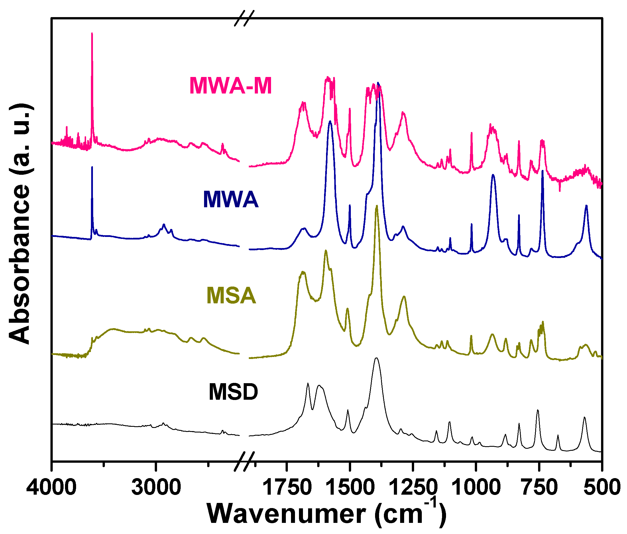
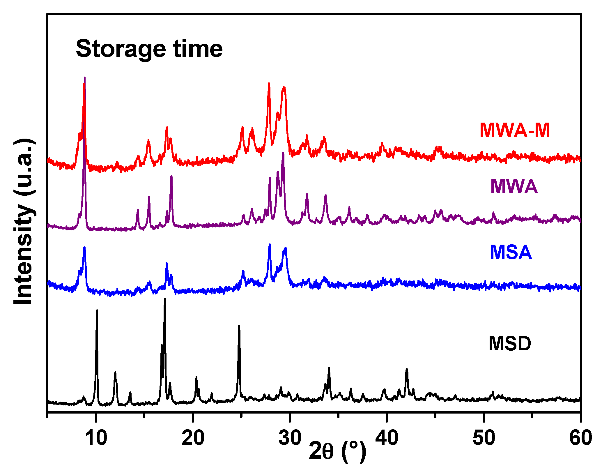
3.1. Structural Characteristics of Synthesized Cu-BDC Crystals

The XRD pattern of the MSD solid synthesized with protocol 1 matched with that simulated from the [Cu(BDC)(DMF)] structure (Figure 1a) [23] and confirms that we obtained a pure Cu-BDC phase with DMF molecules occluded inside. In this MOF the metal centers have a square pyramidal geometry in which the DMF molecules inside the pores stabilize the structure by axial coordination with the Cu2+ atoms through the carbonyl groups. It should be noted that this MOF is isoreticular to MOF-2-DMF, [Zn(BDC)(DMF)] [24,25,26], which was obtained by Clausen et al. [25] (Figure 1a) and in which DMF molecules coordinate axially with Zn2+ atoms. Likewise, the said MOF-2-DMF is a polymorph of the MOF-2, Zn(BDC)·(DMF)(H2O) obtained by Yagui et al. [27] at room temperature with the difference that, in such MOF-2, the Zn2+ atoms are coordinated axially to water molecules, leaving the DMF occluded in the porous system [25,27].
Because the usefulness of the MSD structure depends on the evacuation of DMF, the Cu-MOF synthesis was also carried out by replacing all of the described solvent by acetone (protocol 2). The latter solvent allowed to obtain other DMF-free MOFs, such as ZIF-8 [28], NiFe MOF [29] and UiO-66 [30]. The obtained MSA solid exhibited an XRD pattern consistent with that simulated from the DMF-free [Cu(BDC)] structure [31] (Figure 1b). This is relevant because it implies that, under solvothermal conditions, the DMF can be totally replaced by acetone to obtain the desolvated form of this Cu-BDC. To the best of our knowledge this structural version had only been accessible when applying temperatures higher than 220 °C via the desolvation of [Cu(BDC)(DMF)] [23], by heating at 140 °C in a vacuum for 8 h [32], or after prolonged Soxhlet extraction processes with methanol [31]. It should be noted at this point that desolvations at high temperatures [23,32] often entail loss of crystallinity and/or distortions of the MOF structure. Acetone contains carbonyl groups that can coordinate with the Cu2+ atoms and stabilize the structure of this Cu-MOF, with the advantage that the smaller kinetic diameter and higher volatility of this solvent allow access to the evacuated [Cu(BDC)] form after a simple drying at 80 °C.
On the other hand, in addition to avoiding the use of toxic and expensive solvents such as DMF [33,34,35] another approach to the development of more sustainable synthetic protocols is the implementation of energy-efficient procedures that allow reaction times to be reduced. In this sense, the microwave-assisted synthesis of MOFs has proven to be a useful option [36,37,38]. Therefore, this methodology was explored with all of the other Cu-BDC synthesis parameters conserved and using acetone as a solvent (protocol 3). This synthesis, performed over 3 h, led to our obtaining of an MWA solid (Figure 1c) that exhibited a diffraction pattern analogous to that of the [Cu2(OH)2(BDC)] structure which was reported by Abdelouhab et al. [39]. It can be seen that this XRD pattern (Figure 1) is totally different to that of the solvated (MSD) or desolvated (MSA) versions of the above-described Cu-MOFs. This implies that the slower formation kinetics operating under solvothermal conditions leads to more thermodynamically favorable structures [40,41] such as MSD and MSA, while faster kinetics using a microwave-assisted protocol modifies the obtained structure. In other words, starting from the same mixture of reagents and using acetone as solvent, [Cu2(OH)2(BDC)] or [Cu(BDC)] phases can be preferably obtained by applying a microwave protocol or by using a conventional solvothermal synthesis procedure, respectively. The coexistence of kinetic and thermodynamic factors during the formation process of MOFs has been reported for several cases, such as for MIL-101-Cr and MIL-53-Cr [40] as well as for MIL-100, MIL-110 and MIL-96 [41]. Therefore, the structures of the MWA and MSA samples can be considered the kinetically and thermodynamically most favorable phases of Cu-BDC, respectively, and which can be selectively modulated with the synthetic approach.
An aspect to highlight in the MSA and MWA solids is the presence of residual linker (2θ = 17.3°, 25.1° and 27.9°), which is predictable given the low solubility of H2BDC in acetone at room temperature compared with DMF, for which solubility values (molar fractions) of between 0.0283 [42] and 0.0315 [43] at 25 °C have been reported. With the intention of reducing the amount of residual linker in the solid that was synthesized via microwave, protocol 4 was carried out employing an acetone–methanol mixture as a solvent to improve the solubility of H2BDC. It can be seen (Figure 1d) that the obtained MWA-M solid did not show detectable XRD signals of the linker. Furthermore, the diffraction pattern showed similarities with both the [Cu(BDC)] and the [Cu2(OH)2(BDC)] phases. That is, the incorporation of methanol into the reaction system promoted the formation of a solid with mixed structural characteristics (Figure 1d). To analyze this aspect, the ability of acetone and methanol to generate heat from microwave irradiation must be considered. The loss angle (δ), which is generally expressed as its tangent (tan δ), is a parameter that allows a comparison of the ability of solvents to convert microwaves into thermal energy [44] and in the case of acetone and methanol these have values of 0.042 and 0.941, respectively. That is, methanol interacts better with microwave radiation and results in a faster heating rate [44]. This means that the acetone/methanol mixture required less microwave power both to reach the synthesis temperature and to maintain it during the treatment time. As a consequence, there was a slowdown in the formation kinetics of the Cu-BDC, leading to a mixture of the [Cu2(OH)2(BDC)] and [Cu(BDC)] phases. This is also consistent with what has been observed for the solvothermal treatment in which only [Cu(BDC)] was obtained given the lower crystallization rate under these experimental conditions.
At this point of the discussion an important aspect to highlight is that, although copper terephthalates (Cu-BDCs) have been widely studied and the diffraction pattern obtained for the MWA solid has been informed, reports in the literature of solids with different diffraction patterns have often been considered to be the same material as those shown in Table 1. In addition, it should be emphasized that, although the MSD (solvated form) and MSA (desolvated form) solids presented XRD patterns analogous to the Lavoisier Institute materials that Férey et al. named MIL-53, copper terephthalates, differ from MIL-n in that the latter are obtained from trivalent cations, such as Cr3+, Al3+, Fe3+ [45,46,47,48]. Therefore, it is not appropriate to use MIL-53 terminology to identify a terephthalate formed from Cu2+.
Figure 1. XRD patterns of the synthesized Cu-MOFs: (a) MSD, (b) MSA, (c) MWA, (d) MWA-M. The simulated profiles were generated from the following files: (a) [Cu(BDC)(DMF)] (CCDC 687690) and [Zn(BDC)(DMF)] (CCDC 266351), (b) [Cu(BDC)] (CCDC 1056985), (c) [Cu2(OH)2(BDC)] (CCDC 1192591).
Coatings 13 02065 g001
The infrared spectra of the solids showed typical profiles of Cu-BDC-type structures (Figure 2), with signals at 1595 and 1390 cm−1 due to the νasCOO and νsCOO modes, respectively [52,58,59]. These peaks were noticeably displaced with respect to the same modes found in H2BDC (1679 and 1281 cm−1), showing the formation of therephtalates [53,57,59]. This was also confirmed by the band at 565 cm−1 associated with the νCu-O vibrational mode [49,59,60], which was observed in the spectra of all of the synthesized solids. The peaks at 1505, 1019, and 830 cm−1 are due to vibrations of the phenyl group of the bendenedicarboxylate ion (BDC2−) [52,57,58]. Furthermore, each of the Cu-BDCs showed unique signals inherent to their structural qualities. In this sense, MSD exhibited peaks at 2954, 1666, 1103 and 675 cm−1 due to the νC-H, νC=O, ρr1C-N and νO=C-N modes, respectively, of the DMF [61]. Furthermore, MWA and MWA-M spectra exhibited a sharp band at 3609 cm−1 due to free OH groups [62,63], in line with the structure of the hydroxyterephthalates [Cu2(OH)2(BDC)] (MWA) and [Cu(BDC)]/[Cu2(OH)2(BDC)] (MWA-M).
The different structural features of the synthesized Cu-MOFs were also reflected in their morphology and particle size. The MSD solid appeared as microcrystals with cubic morphology, similar to that reported for [Cu(BDC)(DMF)] obtained solvothermally [52,53]. These crystals were formed by stacking two-dimensional sheets with average sizes (length, width, thickness) of 5.2 µm × 3.5 µm × 2.4 µm, respectively (Figure 3a). Meanwhile, MSA particles showed smaller size with two types of morphologies: 2D sheets somewhat more dispersed than the previous case (0.7 µm × 0.5 µm × 50 nm) and globular structures (1 µm) compatible with the remaining H2BDC, in line with what was determined by XRD (Figure 1b and Figure 3b). On the other hand, the MWA sample exhibited rod-shaped microcrystals of ~1.5 µm long and ~0.3 µm thick (Figure 3c). Finally, the particles of the sample MWA-M showed a similar morphological appearance to these of MSA, presenting 2D nanosheets (2.1 µm × 1.2 µm × 100 nm thickness) that were much more dispersed (Figure 3d) compared with MSA and with a much lower proportion of H2BDC residues.
The morphologies of the materials are consistent with their structures, as, in the Cu-MOF MSD the 2D sheets tend to stack due to interactions between the DMF molecules between adjacent layers (Figure 4a). Analogous behavior has been observed for counterpart polymorphic structures based on zinc, such as [Zn(BDC)(DMF)] [25] and Zn(BDC)·(DMF)(H2O) [27]. Meanwhile, MSA, being a desolvated version and not having molecules coordinated to the Cu2+ atoms that promote said interaction (Figure 4b), appeared in the form of more dispersed sheets. On the other hand, the morphological difference of MWA with respect to MSD and MSA can be explained by the different framework arrangement in this Cu-BDC, which was promoted by the faster formation kinetics achieved by microwave heating (Figure 4c). The MWA-M solid was made up of much more dispersed 2D sheets compared with the MWA case, due to the fact that the incorporation of methanol into the synthesis medium slowed down the formation kinetics leading the crystals to arrange with an MSA-like morphology.

3.2. Evolution of the Cu-BDC Structures with Temperature and Time

3.2.1. Structural Evolution with Temperature

The thermal evolution of the different Cu-BDCs structures was monitored by T-XRD (Figure 5). It can be seen that the XRD pattern of the MSD sample was transforming at very low temperatures (50 °C) by a splitting of the 12.0° signal into two signals at 11.8° and 12.4° (Figure 5a), while at 250 °C they almost disappeared. In parallel, two peaks emerged at 8.3° and 9.2°, in line with the process of framework expansion of this MOF that occurs upon removal of DMF and which accounts for its breathing effect [23]. This desolvated structure continued to evolve up to 450 °C, when the thermal collapse of the MOF began, in line with the TGA studies (Figure S3). Finally, intense peaks of a metallic copper phase emerged (2θ = 43.0°, 50.1° and 73.6°, JCPDS-ICDD 3-1005).
On the other hand, the in situ thermal treatment of MWA (Figure 5b) did not show any structural evolution and only the beginning of the collapse of the MOF, at about 350 °C, was observed, in good agreement with the TGA profiles (Figure S3), before ultimately being transformed into a metallic copper phase. Thus, MWA is a rigid copper terephthalate without a breathing effect. It is important to highlight that the XRD pattern of this solid is analogous to that of the Zn-MOF reported by Huang et al. [63] which they called MOCP-H. This structure has a terminal OH strongly bonded to the MOF, which was also observed by FTIR in the MWA solid. The aforementioned authors have pointed out that the MOCP-H structure is closely related to the so-called MOCP-L (a low-quality MOF-5 prepared at room temperature [64]), as MOCP-H transforms into MOCP-L when heated above 300 °C. In a similar way to that which was observed in our study, Huang et al. found that MOCP-L, in contact with ambient humidity, irreversibly transforms into MOCP-H’, which cannot return to the previous format after thermal treatment. Finally, it should be noted that the structural behavior with temperature of the MWA-M solid was shown to be similar to that of the sample MWA, both of which are formed by rigid structures that are not modified by the thermal treatment (Figure 5c).

3.2.2. Structural Evolution with Exposition to Ambient Conditions

A crucial aspect of these Cu-BDCs when used in aqueous-based electrocatalytic applications is their structural stability when exposed to humidity and ambient conditions. Therefore, the Cu-MOFs were analyzed after having been preserved in sample holders over a long time (12–24 months) after their synthesis. As Figure 6 shows, the desolvated Cu-BDCs (MSA and MWA-M) form evolved into a copper hydroxyterephthalate (MWA) while the solvated MSD form retained its structure. This fact demonstrates the high sensitivity of the desolvated versions of this Cu-BDC type to ambient conditions, which could lead to certain effects on applications involving contact with water. After comparing the physicochemical qualities of all of the synthesized Cu-BDCs, the MWA-M material seems to be a thermally robust and stable phase under ambient conditions, given the fact that it was obtained in pure form with a short treatment of 3 h and replacing DMF by acetone. Furthermore, this Cu-BDC crystallized with a morphological arrangement of nanosheets which were much more isolated than those that form the conventional [Cu(BDC)(DMF)]. Furthermore, such a morphology suggests the possibility of the exfoliation of the material, as discussed below.

3.3. Exfoliated Cu-BDC from the MWA-M Material

In order to attempt to generate an exfoliated version of MWA-M, this solid was subjected to a treatment in an ultrasonic bath with water at 60 °C for periods of 2 h to 6 h. In Figure 7a it can be seen that MWA-M crystals appeared as relatively dispersed sheets of 1–5 µm in size and thicknesses of ~50 nm. It can also be seen that these sheets were made up of an assembly of nanometric structures (inset in Figure 7a). When this solid was treated for 2 h with ultrasound a simultaneous process of exfoliation and rupture of the sheets was evidenced, generating a material made up of nanometric fragments that were aggregated with each other because of the drying process that occurred after carrying out such treatment (Figure 7b). By extending the ultrasound time up to 6 h, the material continued to disintegrate, leading to a solid made up of highly dispersed nanostructures about 50 nm in size, similar to the fragments of the original nanosheets (Figure 7c). The physicochemical qualities of these Cu-BDCs make them very attractive for electrochemical applications, so their electrochemical responses were analyzed in detail as discussed below.

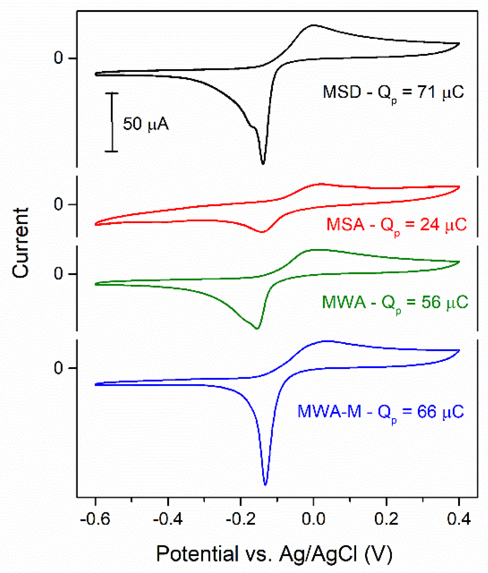
3.4. Electrochemical Behavior of Cu-BDC Coatings

The redox and electron transfer processes verified by copper centers at the surface and the charge-transport properties within the Cu-MOFs films were analyzed by cyclic voltammetry. Cyclic voltammograms (CVs) were acquired on Cu-MOF films supported on GC RDEs (as described in Section 2.4) in buffered neutral solution (PBS, pH = 7) saturated with inert gas (N2). Typical CVs measured on the different MOFs synthesized in this work are shown in Figure 8, which are stable and repetitive, demonstrating responses that are similar to those of other Cu-based MOFs, such as HKUST-1 and Cu-MOF-74 [14].
In all cases the stable CVs show a current increase during the anodic sweep due to the oxidation of Cu+ to Cu2+ at potentials higher than −0.1 V vs. Ag/AgCl. This oxidation current passes through a maximum, decreases slightly, and tends to stabilize at a nearly constant value. Upon changing the direction of the potential scan toward negative values, the CVs show a sharper cathodic peak at potentials between −0.05 and −0.25 V vs. Ag/AgCl, which is caused by the reduction of the electrochemically formed Cu2+ to Cu+. As a first observation, these CVs disclose the redox capability inherent to the copper centers and show that the structure of the Cu-MOF films guarantees a proper wiring of these sites, allowing electron transfer between them without appreciable modification of the MOF structure. The involved reduction charge (Qp) can be calculated from integration of the background-subtracted current of the cathodic peak. Assuming that all of the voltametric charge is related to the Cu2+/Cu+ couple, Qp indicates the number of moles of copper centers (nCu = Qp/F, where F is the Faraday constant) that participated in this redox process. These values are indicated along with the respective CVs in Figure 8. As can be seen, the MOFs MSA and MWA showed smaller Qp values, indicating lesser amounts of electrochemically active Cu centers in these MOFs as compared with the respective MSD and MWA-M. Those MOFs (synthesized in acetone) contained significant amounts of unreacted BDC, which probably blocked the connection of a large fraction of material, both preventing an efficient inter-particle contact and hampering the access of the electrolyte to the whole crystal surface.
The voltametric profiles verified during the anodic scan reveal that the oxidation of Cu+ to Cu2+ is a process that occurs not only on the Cu surface sites that are in direct contact with the electrolyte (CuS), but also extends towards the interior of the MOF crystal structure in the films with a slow charge-transport rate. Such behavior, which was also observed in other Cu-MOFs [14], probably involves a complex charge-transfer mechanism. Contrarily, the reverse process (reduction of Cu2+) is fast and shows as a relatively sharp cathodic peak. Thus, both the anodic Cu+/Cu2+ plateau and the respective reduction peak contain surface and volumetric contributions coming from the redox processes of CuS and inner sites. In particular, in some CVs (such as those from MSD and MWA) the reduction peak seems to be in fact a convolution of two or more peaks, which probably reveal the existence of copper centers with different coordination environments. The electrochemical differences observed among each synthesized Cu-MOF reflects their singular features, as they exhibited different structural variants and particle sizes, which in turn were defined by the synthetic conditions, such as the solvent or the heating method (solvothermal or microwave).
Overall, the largest availability of Cu centers was attained with MWA-M samples. Thus, in order to evaluate the long-term electrochemical stability of this material, prolonged potential cycling (up to 500 cycles) was applied to the MWA-M electrodes and the resulting CVs and morphologies (inspected by SEM on thoroughly washed and dried films) were compared, as shown in Figure S4. Only a slight decrease of the Qp values were verified upon carrying out the first cycles, and no significant changes were detected after these first changes. This indicates that most of the material that was initially connected remained unaltered on the electrode. Further, the SEM images of the films before and after use show only some minor changes due to swelling of the Nafion-based film upon hydration and to erosion caused by the electrolyte during rotation.
As shown in Figure 7, the MWA-M material is composed partially of stacked two-dimensional nano-sheets that are almost free of BDC linker. Furthermore, it was possible to exfoliate and break these sheets through sonication of the suspended MWA-M material as described in Section 3.3. Thus, in order to visualize the effect of this treatment, CVs of as-prepared MWA-M and of MWA-M that had been sonicated at different times (2 h and 6 h) were measured, the results of which are shown in Figure 9. By comparing the CVs of MWA-M with and without sonication treatment it is possible to verify an increase of the Qp values (i.e., of the amount of oxidized copper) with sonication, the values of which are indicated next to each CV in Figure 9. As the anodic potential was the same in all of these CVs, this increase was most likely caused by a higher amount of CuS centers due to the much larger exposed geometric surface area of the MOF, induced by sonication (which was previously verified by SEM). The calculated peak charges lead to nCu values of 6.8 × 10⁻¹⁰ (as prepared MWA-M), 8.5 × 10⁻¹⁰ (MWA-M sonicated 2 h), and 10.3 × 10⁻¹⁰ (MWA-M sonicated 6 h) moles. As the electrodes contained approximately 6 µg of MOF, these values lead to nearly 1.1 × 10⁻⁴, 1.5 × 10⁻⁴, and 1.7 × 10⁻⁴ moles of Cu per gram of MOF. Taking into account the fact that, according to the thermogravimetric analysis (TGA) of the MWA-M sample (Figure S3), the Cu content was approximately 33 wt.%, i.e., ~5 × 10⁻³ moles of Cu per gram, it is clear that the fraction of Cu involved in these redox processes (over the CV timescales) is only around 2% to 4%.
The anodic potential limit is an experimental parameter that should allow one to increase the amount of oxidized CuV sites. The effect of this parameter is shown in the CVs of Figure 10a. Higher potential limits of the CVs induce larger Qp values deriving from an increase of oxidized inner centers. Remarkably, on sonicated MWA-M electrodes such dependence is increased proportionally to the sonication time by a constant value (independent of the anodic potential) (Figure 10b), so it is likely that such shifting is caused only by the increase of the active area, and so of CuS sites, on these Cu-MOFs samples.
Having verified the efficient wiring and stable redox response of the copper centers in these MWA-M MOFs in neutral PBS solution, their electrocatalytic activity for the oxygen reduction reaction (ORR) was evaluated by cyclic voltammetry in O2-saturated neutral media. Firstly, a comparison of the CVs of GC/MWA-M electrodes in the absence and presence of O2 was carried out to directly visualize the capability of the material to electro-reduce dissolved oxygen. A typical stable CV that exemplifies the responses of all MWA-M electrodes is shown in Figure 11a.
The Cu2+/Cu+ reduction peak that was detected between −0.05 and −0.25 V in N2-saturated solution was also present in O2-saturated solution with no appreciable changes. This is a marked difference between the ORR electrocatalytic behavior of this MOF coating and that of other porous MOFs such as Cu-MOF-74, where the ORR occurring at the active sites located in the nanopores caused a clear change of the Cu2+/Cu+ voltametric peaks [14]. Furthermore, ORR currents were only clearly evident at potentials lower than −0.3 V, i.e., more cathodic than the Cu2+/Cu+ process. This indicates that, while the ORR truly occurs on these MWA-M MOFs, its mechanism does not involve a direct interaction between the dissolved O2 molecules and the Cu centers, as it seems to happen on microporous MOFs [14]. In other words, the ORR is not mediated by the Cu2+/Cu+ couple and only proceeds on the external MOF surface exposed to the electrolyte. Moreover, in order to obtain the complete polarization curve for the ORR it is possible to extend the cathodic potential only down to −1 V, as below these cathodic values the material can be electro-reduced. Thus, Figure 11b shows ORR CVs with current densities (relative to geometric electrode area) measured on GC-supported MWA-M coated (with and without sonication) RDEs over an extended potential interval at a high rotation rate (1600 rpm). The ORR CVs measured on sonicated samples show higher currents for the ORR over the whole analyzed potential interval. It should be taken into account that the ORR mass-transport limiting current densities (jL) that can be attained on a smooth RDE at this size and for this rotation rate (jL = Bω½, where B ≅ 0.44 mA cm−2s½rad−½ [65]) should have values in the order of 5.7 mA cm−2. As can be seen in Figure 11b, the ORR current densities detected on the GC/MWA-M RDEs were still smaller than the maximum values expected for a smooth RDE, which is indicative that the reaction still operates under mixed conditions over these potentials. An accurate calculation of the real electroactive area through the measured Qp values is not feasible as these values receive contributions from surface and volumetric Cu sites. However, it is possible to perform a rough estimation by using the double-layer capacitance (Cdl) measured from the voltametric capacitive currents [66] registered at potentials below −0.3 V in O2-free electrolyte (as shown in Figure S5). Then, by assuming a specific capacitance value in the order of that adopted for edge-plane graphite (~60 μF cm−2 [67]), electroactive areas of 0.232 ± 0.015 cm2 and 0.458 ± 0.013 cm2 were calculated for MWA-M and sonicated MWA-M (2 h), respectively. Thus, such an increase of the specific electroactive area explains the larger ORR currents verified on the sonicated electrode. In addition, the long-term stability of ORR currents was evaluated by amperometric current–time curves for 5 min measured at different potentials. These curves (some of them shown in Figure S6) indicate a very stable performance of MWA-M for electro-reducing oxygen sustaining constant steady-state currents (indicated in Figure 11b) for long times.
It is interesting to contrast the performance of this material as an ORR electrocatalyst in neutral media with those of other recently reported highly porous Cu-based MOFs, such as HKUST-1 [68] and Cu-MOF-74 [14]. In that sense, while these MOFs are capable of electro-reducing oxygen at less cathodic potentials (or lesser overpotentials), the current densities attained on sonicated MWA-M electrodes (near 2–3 mA cm−2) were very stable and in general around three-fold larger than those reached by the porous MOFs. This is probably caused by a more open morphology of the sonicated nanoflakes, which favors the access of dissolved oxygen to the Cu-based active centers. The required overpotentials for attaining these significant current densities are more cathodic than −0.9 V (estimated considering that the reversible oxygen electrode potential in neutral medium is 0.59 V vs. Ag/AgCl). Though these values are larger than those verified on Pt and on enzyme-based electrodes [65] (the best catalysts materials so far), there still are many options to keep decreasing this difference by improving the dispersion of the MWA-M nanosheets.

4. Conclusions

The Cu-terephthalate-based MOFs synthesized in this work have proven to be materials that are capable of functioning as electrocatalysts, owing to their good charge transport capability to the active Cu sites. It has been shown that the electrochemical response of this type of copper terephthalate has a strong dependence on its structural features, which can be regulated through a structural engineering approach by applying modifications to the synthetic protocols. The most promising variants of Cu-MOFs are those synthesized through the newly described microwave-assisted method, which employs a mixture of acetone and methanol as a solvent with which to reduce the excess of unreacted linker remaining from the synthesis (which causes a decrease in the connectivity of Cu sites). Using this synthesis method, the material grows as stacked nanometric-thick flakes, which is a highly intriguing morphology for its potential use as an electrocatalyst. While the structure lacks the typical nanoporosity of other MOFs, its surface area can be significantly increased through mechanical exfoliation, as was undertaken in this study using ultrasonication. We have confirmed, by cyclic voltammetry the significant increase in electroactive surface area when applying this treatment, and also verified its strong effect on the material performance as an electrocatalyst for the oxygen reduction reaction. This evidence opens up the possibility of using this material for the development of highly dispersed catalysts supported on carbon that can be employed as efficient noble-metal-free electrodes (in this case, for oxygen reduction).

Supplementary Materials

The following supporting information can be downloaded at: https://www.mdpi.com/article/10.3390/coatings13122065/s1, Figure S1: Large-scale SEM photograph of a GC-supported MWA-M/Nafion® film and EDS analyses. Figure S2: SEM photographs of MWA-M/Nafion® film thicknesses. Figure S3: TGA curves of the synthesized Cu-BDCs. Figure S4: Obtained CVs and corresponding SEM photographs of a GC-supported MWA-M/Nafion® film before and after prolonged potential cycling. Figure S5: Measurements of double layer capacitances on MWA-M and on MWA-M sonicated for 2 h supported on GC RDEs. Figure S6: Oxygen-reduction amperometric current–time curves measured at different potentials on a GC-supported MWA-M/Nafion® film.

Author Contributions

S.L.R.: formal analysis, investigation, visualization. G.A.O.-M.: formal analysis, visualization, writing—original draft. M.S.-S.: formal analysis, visualization, resources, writing—review and editing, J.L.F.: methodology, funding acquisition resources, supervision, visualization, writing—original draft, writing—review and editing. J.M.Z.: conceptualization, methodology, funding acquisition, project administration, resources, visualization, supervision, writing—original draft, writing—review and editing. All authors have read and agreed to the published version of the manuscript.

Funding

This work was supported by the Agencia Nacional de Promoción Científica y Tecnológica of Argentina (Project PICT 1880) and the Universidad Nacional del Litoral (Project CAI+D 00168LI). MSS acknowledges MCIN/AEI/10.13039/501100011033, European Union “NextGenerationEU”/PRTR (TED2021-131143B-I00), MCIN/AEI/10.13039/501100011033 and “ERDF A way of making Europe” (PID2022-136321OB-C21). The authors also wish to thank the Consejo Nacional de Investigaciones Científicas y Técnicas (CONICET).

Institutional Review Board Statement

Not Applicable.

Informed Consent Statement

Not applicable.

Data Availability Statement

Data are contained within the article and supplementary materials.

Conflicts of Interest

The authors declare no conflict of interest.

References

  1. Sanati, S.; Morsali, A.; García, H. Metal-organic framework-based materials as key components in electrocatalytic oxidation and reduction reactions. J. Energy Chem. 2023, 87, 540–567. [Google Scholar] [CrossRef]
  2. Su, Z.; Huang, Q.; Guo, Q.; Hoseini, S.J.; Zheng, F.; Chen, W. Metal–organic framework and carbon hybrid nanostructures: Fabrication strategies and electrocatalytic application for the water splitting and oxygen reduction reaction. Nano Res. Energy 2023, 2, e9120078. [Google Scholar] [CrossRef]
  3. Wu, S.; Qu, X.; Zhu, J.; Liu, X.; Mao, H.; Wang, K.; Zhou, G.; Chi, J.; Wang, L. Recent advances in metal-organic frameworks derived electrocatalysts for oxygen reduction reaction. J. Alloys Compd. 2024, 970, 172518. [Google Scholar] [CrossRef]
  4. Liao, P.-Q.; Shen, J.-Q.; Zhang, J.-P. Metal–organic frameworks for electrocatalysis. Coord. Chem. Rev. 2018, 373, 22–48. [Google Scholar] [CrossRef]
  5. Yang, C.; Ma, X.; Zhou, J.; Zhao, Y.; Xiang, X.; Shang, H.; Zhang, B. Recent advances in metal-organic frameworks-derived carbon-based electrocatalysts for the oxygen reduction reaction. Int. J. Hydrogen Energy 2022, 47, 21634–21661. [Google Scholar] [CrossRef]
  6. Dey, A.; Singha, A. Bioinspired Electrocatalysis for the Oxygen Reduction Reaction; Elsevier: Amsterdam, The Netherlands, 2018. [Google Scholar] [CrossRef]
  7. Kato, M.; Yagi, I. Electrocatalytic Oxygen Reduction at Multinuclear Metal Active Sites Inspired by Metalloenzymes. E J. Surf. Sci. Nanotechnol. 2020, 18, 81–93. [Google Scholar] [CrossRef]
  8. McCrory, C.C.L.; Ottenwaelder, X.; Stack P, T.D.; Chidsey, C.E.D. Kinetic and Mechanistic Studies of the Electrocatalytic Reduction of O2 to H2O with Mononuclear Cu Complexes of Substituted 1,10-phenanthrolines. J. Phys. Chem. A 2007, 111, 12641–12650. [Google Scholar] [CrossRef]
  9. Batten, S.R.; Champness, N.R.; Chen, X.; Garcia-Martinez, J.; Kitagawa, S.; Öhrström, L.; Keeffe, M.O.; Suh, M.P.; Reedijk, J. Terminology of metal–organic frameworks and coordination polymers. Pure Appl. Chem. 2013, 85, 1715–1724. [Google Scholar] [CrossRef]
  10. Zhang, Y.; Gao, L.; Ma, S.; Hu, T. A multifunctional metal-organic framework with a μ3-OH-site for gas and vapor sorption and selective detection of nitrofurantoin. J. Mater. Chem. C 2022, 10, 1136–1143. [Google Scholar] [CrossRef]
  11. Zhang, S.; Wang, B.; Li, S.; Li, X.; Liu, G.; Zhang, Z.; Wang, X. Metal-/carboxylate-directed four d10 piperazine-amide-based coordination polymers for the fluorescent detection of nitrophenol and nitroaniline in various water environments. J. Mol. Struct. 2024, 1297, 136929. [Google Scholar] [CrossRef]
  12. Lei, N.; Li, W.; Zhao, D.; Li, W.; Liu, X.; Liu, L.; Yin, J.; Muddassir, M.; Wen, R.; Fan, L. A bifunctional luminescence sensor for biomarkers detection in serum and urine based on chemorobust Nickel(II) metal-organic framework. Spectrochim. Acta—Part A Mol. Biomol. Spectrosc. 2024, 306, 123585. [Google Scholar] [CrossRef]
  13. Fernández-Morales, J.M.; Lozano, L.A.; Castillejos-López, E.; Rodríguez-Ramos, I.; Guerrero-Ruiz, A.; Zamaro, J.M. Direct sulfation of a Zr-based metal-organic framework to attain strong acid catalysts. Microporous Mesoporous Mater. 2019, 290, 109686. [Google Scholar] [CrossRef]
  14. Rodríguez, S.L.; Sánchez-Sánchez, M.; Zamaro, J.M.; Fernández, J.L. Understanding electron transfer processes and oxygen reduction electrocatalysis in nanocrystalline Cu-MOF-74. J. Electroanal. Chem. 2022, 918, 116489. [Google Scholar] [CrossRef]
  15. Ren, Y.; Chia, G.H.; Gao, Z. Metal-organic frameworks in fuel cell technologies. Nano Today 2013, 8, 577–597. [Google Scholar] [CrossRef]
  16. Shit, S.C.; Mondal, I.; Pendem, S.; Bai, L.; Park, J.Y.; Mondal, J. MOF-Derived Bifunctional Iron Oxide and Iron Phosphide Nanoarchitecture Photoelectrode for Neutral Water Splitting. ChemElectroChem 2018, 5, 2842–2849. [Google Scholar] [CrossRef]
  17. Abdelkader-Fernández, V.K.; Fernandes, D.M.; Balula, S.S.; Cunha-Silva, L.; Pérez-Mendoza, M.J.; López-Garzón, F.J.; Pereira, M.F.; Freire, C. Noble-Metal-Free MOF-74-Derived Nanocarbons: Insights on Metal Composition and Doping Effects on the Electrocatalytic Activity Toward Oxygen Reactions. ACS Appl. Energy Mater. 2019, 2, 1854–1867. [Google Scholar] [CrossRef]
  18. Majidi, L.; Ahmadiparidari, A.; Shan, N.; Misal, S.N.; Kumar, K.; Huang, Z.; Rastegar, S.; Hemmat, Z.; Zou, X.; Zapol, P.; et al. 2D Copper Tetrahydroxyquinone Conductive Metal–Organic Framework for Selective CO2 Electrocatalysis at Low Overpotentials. Adv. Mater. 2021, 33, 2004393. [Google Scholar] [CrossRef] [PubMed]
  19. Huang, H.; Zhao, Y.; Bai, Y.; Li, F.; Zhang, Y.; Chen, Y. Conductive Metal–Organic Frameworks with Extra Metallic Sites as an Efficient Electrocatalyst for the Hydrogen Evolution Reaction. Adv. Sci. 2020, 7, 2000012. [Google Scholar] [CrossRef]
  20. Duan, J.; Chen, S.; Zhao, C. Ultrathin metal-organic framework array for efficient electrocatalytic water splitting. Nat. Commun. 2017, 8, 15341. [Google Scholar] [CrossRef]
  21. Rathi, A.K.; Gawande, M.B.; Zboril, R.; Varma, R.S. Microwave-assisted synthesisCatalytic applications in aqueous media. Coord. Chem. Rev. 2015, 291, 68–94. [Google Scholar] [CrossRef]
  22. Kumar, R.; Oh, J.-H.; Kim, H.-J.; Jung, J.-H.; Jung, C.-H.; Hong, W.G.; Kim, H.J.; Park, J.Y.; Oh, I.-K. Nanohole-Structured and Palladium-Embedded 3D Porous Graphene for Ultrahigh Hydrogen Storage and CO Oxidation Multifunctionalities. ACS Nano 2015, 9, 7343–7351. [Google Scholar] [CrossRef] [PubMed]
  23. Carson, C.G.; Hardcastle, K.; Schwartz, J.; Liu, X.; Hoffmann, C.; Gerhardt, R.A.; Tannenbaum, R. Synthesis and Structure Characterization of Copper Terephthalate Metal-Organic Frameworks. Eur. J. Inorg. Chem. 2009, 2009, 2338–2343. [Google Scholar] [CrossRef]
  24. Getachew, N.; Chebude, Y.; Diaz, I.; Sanchez-Sanchez, M. Room temperature synthesis of metal organic framework MOF-2. J. Porous Mater. 2014, 21, 769–773. [Google Scholar] [CrossRef]
  25. Clausen, H.F.; Poulsen, R.D.; Bond, A.D.; Chevallier, M.-A.S.; Iversen, B.B. Solvothermal synthesis of new metal organic framework structures in the zinc-terephthalic acid-dimethyl formamide system. J. Solid State Chem. 2005, 178, 3342–3351. [Google Scholar] [CrossRef]
  26. Schweighauser, L.; Harano, K.; Nakamura, E. Experimental study on interconversion between cubic MOF-5 and square MOF-2 arrays. Inorg. Chem. Commun. 2017, 84, 1–4. [Google Scholar] [CrossRef]
  27. Li, H.; Eddaoudi, M.; Groy, T.L.; Yaghi, O.M. Establishing Microporosity in Open Metal-Organic Frameworks: Gas Sorption Isotherms for Zn(BDC) (BDC = 1,4-benzenedicarboxylate). J. Am. Chem. Soc. 1998, 120, 8571–8572. [Google Scholar] [CrossRef]
  28. Bustamante, E.L.; Fernández, J.L.; Zamaro, J.M. Influence of the solvent in the synthesis of zeolitic imidazolate framework-8 (ZIF-8) nanocrystals at room temperature. J. Colloid Interface Sci. 2014, 424, 37–43. [Google Scholar] [CrossRef]
  29. Jia, J.; Wei, L.; Li, F.; Yu, C.; Yang, K.; Liang, T. In situ growth of NiFe MOF/NF by controlling solvent mixtures as efficient electrocatalyst in oxygen evolution. Inorg. Chem. Commun. 2021, 128, 108605. [Google Scholar] [CrossRef]
  30. Lozano, L.A.; Iglesias, C.M.; Faroldi, B.M.C.; Ulla, M.A.; Zamaro, J.M. Efficient solvothermal synthesis of highly porous UiO-66 nanocrystals in dimethylformamide-free media. J. Mater. Sci. 2018, 53, 1862–1873. [Google Scholar] [CrossRef]
  31. Carson, C.G.; Brunnello, G.; Lee, S.G.; Jang, S.S.; Gerhardt, R.A.; Tannenbaum, R. Structure solution from powder diffraction of copper 1,4-benzenedicarboxylate. Eur. J. Inorg. Chem. 2014, 2014, 2140–2145. [Google Scholar] [CrossRef]
  32. Xin, Z.; Bai, J.; Shen, Y.; Pan, Y. Hierarchically Micro- and Mesoporous Coordination Polymer Nanostructures with High Adsorption Performance. Cryst. Growth Des. 2010, 10, 2451–2454. [Google Scholar] [CrossRef]
  33. Kong, X.-J.; Li, J.-R. An Overview of Metal–Organic Frameworks for Green Chemical Engineering. Engineering 2021, 7, 1115–1139. [Google Scholar] [CrossRef]
  34. Kumar, S.; Jain, S.; Nehra, M.; Dilbaghi, N.; Marrazza, G.; Kim, K.-H. Green synthesis of metal–organic frameworks: A state-of-the-art review of potential environmental and medical applications. Coord. Chem. Rev. 2020, 420, 213407. [Google Scholar] [CrossRef]
  35. Chen, J.; Shen, K.; Li, Y. Greening the Processes of Metal-Organic Frameworks Synthesis and their Use in Sustainable Catalysis. ChemSusChem 2017, 10, 3165–3187. [Google Scholar] [CrossRef] [PubMed]
  36. Lozano, L.A.; Devard, A.; Ulla, M.A.; Zamaro, J.M. Cu/UiO-66: A novel nanocatalyst obtained by a microwave-assisted protocol in DMF-free media for the efficient phenol removal via catalytic wet peroxide oxidation. J. Environ. Chem. Eng. 2020, 8, 104332. [Google Scholar] [CrossRef]
  37. Rubio-Martinez, M.; Avci-Camur, C.; Thornton, A.W.; Imaz, I.; Maspoch, D.; Hill, M.R. New synthetic routes towards MOF production at scale. Chem. Soc. Rev. 2017, 46, 3453–3480. [Google Scholar] [CrossRef] [PubMed]
  38. Khan, N.A.; Jhung, S.H. Synthesis of metal-organic frameworks (MOFs) with microwave or ultrasound: Rapid reaction, phase-selectivity, and size reduction. Coord. Chem. Rev. 2015, 285, 11–23. [Google Scholar] [CrossRef]
  39. Abdelouhab, S.; François, M.; Elkaim, E.; Rabu, P. Ab initio crystal structure of copper(II) hydroxy-terephthalate by synchrotron powder diffraction and magnetic properties. Solid State Sci. 2005, 7, 227–232. [Google Scholar] [CrossRef]
  40. Khan, N.A.; Jhung, S.H. Phase-Transition and Phase-Selective Synthesis of Porous Chromium-Benzenedicarboxylates. Cryst. Growth Des. 2010, 10, 1860–1865. [Google Scholar] [CrossRef]
  41. Khan, N.A.; Lee, J.S.; Jeon, J.; Jun, C.-H.; Jhung, S.H. Phase-selective synthesis and phase-conversion of porous aluminum-benzenetricarboxylates with microwave irradiation. Microporous Mesoporous Mater. 2012, 152, 235–239. [Google Scholar] [CrossRef]
  42. Che, Y.-K.; Qu, Y.-X.; Wang, S. Solubilities of Terephthalic Acid, Phthalic Acid, and Isophthalic Acid in Tetrahydrofuran, Cyclohexanone, 1,2-Diethoxyethane, and Acetophenone. J. Chem. Eng. Data 2009, 54, 3130–3132. [Google Scholar] [CrossRef]
  43. Harper, J.J.; Janik, P. Terephthalic Acid Solubility. J. Chem. Eng. Data. 1970, 15, 439–440. [Google Scholar] [CrossRef]
  44. Lidström, P.; Tierney, J.; Wathey, B.; Westman, J. Microwave assisted organic synthesisA review. Tetrahedron 2001, 57, 9225–9283. [Google Scholar] [CrossRef]
  45. Serre, C.; Millange, F.; Thouvenot, C.; Noguès, M.; Marsolier, G.; Louër, D.; Férey, G. Very large breathing effect in the first nanoporous chromium(III)-based solids: MIL-53 or CrIII(OH)·{O2C-C6H4-CO2}·{HO2C-C6H4-CO2H}x·H2Oy. J. Am. Chem. Soc. 2002, 124, 13519–13526. [Google Scholar] [CrossRef] [PubMed]
  46. Loiseau, T.; Serre, C.; Huguenard, C.; Fink, G.; Taulelle, F.; Henry, M.; Bataille, T.; Férey, G. A Rationale for the Large Breathing of the Porous Aluminum Terephthalate (MIL-53) Upon Hydration. Chem. A Eur. J. 2004, 10, 1373–1382. [Google Scholar] [CrossRef]
  47. Millange, F.; Guillou, N.; Walton, R.I.; Grenèche, J.M.; Margiolaki, I.; Férey, G. Effect of the nature of the metal on the breathing steps in MOFs with dynamic frameworks. Chem. Commun. 2008, 39, 4732–4734. [Google Scholar] [CrossRef] [PubMed]
  48. Horcajada, P.; Serre, C.; Maurin, G.; Ramsahye, N.A.; Balas, F.; Vallet-Regí, M.; Sebban, M.; Taulelle, F.; Ferey, G. Flexible Porous Metal-Organic Frameworks for a Controlled Drug Delivery. J. Am. Chem. Soc. 2008, 130, 6774–6780. [Google Scholar] [CrossRef]
  49. Amiri, M.; Tofighi, Z.; Khodayari, A.; Bezaatpour, A.; Sohrabnezhad, S.; Mishyn, V.; Boukherroub, R.; Szunerits, S. Copper-based metal–organic framework decorated by CuO hair-like nanostructures: Electrocatalyst for oxygen evolution reaction. Appl. Organomet. Chem. 2020, 34, e5871. [Google Scholar] [CrossRef]
  50. Anbia, M.; Sheykhi, S. Synthesis of nanoporous copper terephthalate [MIL-53(Cu)] as a novel methane-storage adsorbent. J. Nat. Gas Chem. 2012, 21, 680–684. [Google Scholar] [CrossRef]
  51. Ren, Y.; Shi, M.; Zhang, W.; Dionysiou, D.D.; Lu, J.; Shan, C.; Zhang, Y.; Lv, L.; Pan, B. Enhancing the Fenton-like Catalytic Activity of nFe2O3 by MIL-53(Cu) Support: A Mechanistic Investigation. Environ. Sci. Technol. 2020, 54, 5258–5267. [Google Scholar] [CrossRef]
  52. Kakaei, H.; Beygzadeh, M.; Golbabaei, F.; Ganjali, M.R.; Jahangiri, M.; Shahtaheri, S.J. Preparation of a sepiolite/Cu-BDC nanocomposite and its application as an adsorbent in respirator cartridges for H2S removal. New J. Chem. 2019, 43, 11575–11584. [Google Scholar] [CrossRef]
  53. Huang, K.; Xu, Y.; Wang, L.; Wu, D. Heterogeneous catalytic wet peroxide oxidation of simulated phenol wastewater by copper metal-organic frameworks. RSC Adv. 2015, 5, 32795–32803. [Google Scholar] [CrossRef]
  54. Dang, G.H.; Vu, Y.T.H.; Dong, Q.A.; Le, D.T.; Truong, T.; Phan, N.T.S. Quinoxaline synthesis via oxidative cyclization reaction using metal-organic framework Cu(BDC) as an efficient heterogeneous catalyst. Appl. Catal. A Gen. 2015, 491, 189–195. [Google Scholar] [CrossRef]
  55. Phan, N.T.S.; Nguyen, T.T.; Nguyen, K.D.; Vo, A.X.T. An open metal site metal-organic framework Cu(BDC) as a promising heterogeneous catalyst for the modified Friedländer reaction. Appl. Catal. A Gen. 2013, 464–465, 128–135. [Google Scholar] [CrossRef]
  56. Bagheri, A.R.; Ghaedi, M. Application of Cu-based metal-organic framework (Cu-BDC) as a sorbent for dispersive solid-phase extraction of gallic acid from orange juice samples using HPLC-UV method. Arab. J. Chem. 2020, 13, 5218–5228. [Google Scholar] [CrossRef]
  57. Patil, Y.A.; Shankarling, G.S. Deep eutectic solvent-mediated, energy-efficient synthesis of copper terephthalate metal-organic framework and its application in degradation of an azo dye. Chem. Eng. J. Adv. 2020, 3, 100032. [Google Scholar] [CrossRef]
  58. Tari, N.E.; Tadjarodi, A.; Tamnanloo, J.; Fatemi, S. Facile and fast, one pot microwave synthesis of metal organic framework copper terephthalate and study CO2 and CH4 adsorption on it. J. Porous Mater. 2015, 22, 1161–1169. [Google Scholar] [CrossRef]
  59. da Silva Montani, S.; de Lima, J.F.; Zotin, F.M.Z.; Palacio, L.A. Thermal stability of copper-based MOF under different atmospheres. J. Therm. Anal. Calorim. 2023, 148, 119–131. [Google Scholar] [CrossRef]
  60. Fixman, E.M.; Abello, M.C.; Gorriz, O.F.; Arrúa, L.A. Preparation of Cu/SiO2 catalysts with and without tartaric acid as template via a sol-gel process. Characterization and evaluation in the methanol partial oxidation. Appl. Catal. A Gen. 2007, 319, 111–118. [Google Scholar] [CrossRef]
  61. Jacob, M.M.E.; Arof, A.K. FTIR studies of DMF plasticized polyvinyledene fluoride based polymer electrolytes. Electrochim. Acta 2000, 45, 1701–1706. [Google Scholar] [CrossRef]
  62. Singh, S.J.; Kale, S.R.; Gawande, M.B.; Velhinho, A.; Jayaram, R.V. A synthesis of copper based metal-organic framework for O-acetylation of alcohols. Catal. Commun. 2014, 44, 24–28. [Google Scholar] [CrossRef]
  63. Huang, L.; Wang, H.; Chen, J.; Wang, Z.; Sun, J.; Zhao, D.; Yan, Y. Synthesis, morphology control, and properties of porous metal-organic coordination polymers. Microporous Mesoporous Mater. 2003, 58, 105–114. [Google Scholar] [CrossRef]
  64. Calleja, G.; Botas, J.A.; Orcajo, M.G.; Sánchez-Sánchez, M. Differences between the isostructural IRMOF-1 and MOCP-L porous adsorbents. J. Porous Mater. 2010, 17, 91–97. [Google Scholar] [CrossRef]
  65. Mano, N.; Fernandez, J.L.; Kim, Y.; Shin, W.; Bard, A.J.; Heller, A. Oxygen Is Electroreduced to Water on a “Wired” Enzyme Electrode at a Lesser Overpotential than on Platinum. J. Am. Chem. Soc. 2003, 125, 15290–15291. [Google Scholar] [CrossRef]
  66. Trasatti, S.; Petrii, O.A. Real surface area measurements in electrochemistry. J. Electroanal. Chem. 1992, 327, 353–376. [Google Scholar] [CrossRef]
  67. McCreery, R.L.; Cline, K.K. Carbon Electrodes. In Laboratory Techniques in Electroanalytical Chemistry, 2nd ed.; Kissinger, P.T., Heineman, W.R., Eds.; Marcel Dekker: New York, NY, USA, 1996; pp. 293–330. [Google Scholar]
  68. Jabarian, S.; Ghaffarinejad, A.; Kazemi, H. Electrochemical and solvothermal syntheses of HKUST-1 Metal Organic Frameworks and Comparison of their Performances as Electrocatalyst for Oxygen Reduction Reaction. Anal. Bioanal. Electrochem. 2018, 10, 1611–1619. [Google Scholar]
Figure 2. FTIR spectra of Cu-BDCs: MSD, MSA, MWA and MWA-M.
Coatings 13 02065 g002
Figure 3. SEM images of Cu-BDCs; (a) MSD, (b) MSA, (c) MWA, (d) MWA-M.
Coatings 13 02065 g003
Figure 4. Projection of the copper terephthalate layers on the structures of the synthesized Cu-BDC: (a) MSD, (b) MSA, (c) MWA. The structures were obtained by simulation from the reported crystallographic data using the software Mercury 2020.3.0. CCDC: (a) 687690, (b) 1056985, (c) 1192591.
Coatings 13 02065 g004
Figure 5. T-XRD patterns of the Cu-BDCs: (a) MSD, (b) MWA, (c) MWA-M.
Coatings 13 02065 g005
Figure 6. XRD patterns of synthesized Cu-BDCs after a long time of storage.
Coatings 13 02065 g006
Figure 7. FE-SEM images of MWA-M solids: (a) as synthesized MWA-M, (b) MWA-M after 2 h of ultrasound treatment, (c) MWA-M after 6 h of ultrasound treatment.
Coatings 13 02065 g007
Figure 8. CVs of the different Cu-MOFs synthesized in this work, supported on GC RDEs in 0.2 M PBS (pH = 7) saturated with N2. Scan rate: 0.1 V s−1.
Coatings 13 02065 g008
Figure 9. CVs of as-prepared MWA-M, and of MWA-M sonicated during 2 h and 6 h, supported on GC RDEs. The cathodic peak integrated charges (Qp) calculated from each CV are indicated within the graphs. Scan rate: 0.1 V s−1. Electrolyte: 0.2 M phosphate buffer solution (pH = 7) saturated with N2.
Coatings 13 02065 g009
Figure 10. Effect of the anodic potential limit on the CVs of GC/MWA-M electrodes (a) and on the resulting voltametric peak charge (b). Scan rate: 0.1 V s−1. Electrolyte: 0.2 M phosphate buffer solution (pH = 7) saturated with N2.
Coatings 13 02065 g010
Figure 11. (a) CVs (v = 0.1 V s−1) of MWA-M supported on GC RDE (ω = 400 rpm) in electrolyte saturated with N2 and with O2. (b) Slow CVs (v = 0.01 V s−1) and ORR steady-state currents (symbols) of as-prepared MWA-M and of MWA-M sonicated for 2 h supported on GC RDEs (ω = 1600 rpm) in electrolyte saturated with O2. Electrolyte: 0.2 M phosphate buffer solution (pH = 7). RDE geometric area: 0.071 cm2.
Coatings 13 02065 g011
Table 1. Structural identification of copper terephthalates found in the literature.
Structural Identity Assigned by AuthorsStructural Identity According to XRD Reported by AuthorsReferences
MIL-53(Cu)[Cu2(OH)2(BDC)][49,50,51]
Cu(BDC)[Cu(BDC)(DMF)][52,53,54,55]
Cu-BDC[Cu2(OH)2(BDC)][56,57]
Disclaimer/Publisher’s Note: The statements, opinions and data contained in all publications are solely those of the individual author(s) and contributor(s) and not of MDPI and/or the editor(s). MDPI and/or the editor(s) disclaim responsibility for any injury to people or property resulting from any ideas, methods, instructions or products referred to in the content.

