Article

Contact Analysis for Cycloid Pinwheel Mechanism by Isogeometric Finite Element

1
Shaanxi Key Laboratory of Advanced Manufacturing and Evaluation of Robot Key Components, Baoji University of Arts and Sciences, Baoji 721016, China
2
College of Mechanical and Electrical Engineering, Xi’an Polytechnic University, Xi’an 710048, China
3
School of Materials and Chemical Engineering, Xi’an Technological University, Xi’an 710021, China
*
Authors to whom correspondence should be addressed.
Coatings 2023, 13(12), 2029; https://doi.org/10.3390/coatings13122029
Submission received: 11 November 2023 / Revised: 27 November 2023 / Accepted: 27 November 2023 / Published: 30 November 2023
(This article belongs to the Special Issue Structural, Mechanical and Tribological Properties of Hard Coatings)

Abstract

:
Cycloid drives are generally used in precision machinery requiring high-reduction ratios, such as robot joint (RV) reducers. The contact stress of cycloidal gears greatly affects lifetime and transmission performance. Traditional finite element method (FEM) has less computational efficiency for contact analysis of complex surface. Therefore, in this paper, isogeometric analysis (IGA) was employed to explore the multi-tooth contact problem of the cycloid pinwheel drive. Based on the nonuniform rational B spline (NURBS) curved surface generation method, the NURBS tooth profile of the cycloid gear was reconstructed. In addition, the NURBS surface of the cycloid gear–pin tooth–output pin was generated via the element splicing method. A geometrical analysis model of cycloid pinwheel drive was established to solve the contact force of the meshing pair under different input angles and compared with the finite element method in terms of convergence, resultant accuracy, and solving timeliness. The results show that isogeometric analysis has higher accuracy and efficiency than the finite element method in calculating the contact stress and contact force. The error of the IGA is only 8.8% for 10 × 10 elements in contact, while the error of the finite element method reaches about 40%. The method can improve the contact simulation accuracy of the cycloid drive and provides a reference for the design evaluation of RV reducer.

1. Introduction

Cycloidal drive has various advantages, including high reduction ratio, high transmission efficiency, high load carrying capacity and low noise. So it is widely applied in robotic joints and other transmission fields with high precision transmission [1,2,3,4]. Due to the repeated loading and contact between the gear teeth in the transmission process, it is easy to cause the wear of cycloidal gear profiles in the mechanism, thus affecting the load carrying capacity and transmission efficiency of the mechanism. Hence, it is essential to investigate the contact load and stress characteristics of the cycloid drive.
Currently, most contact analyses for cycloid pinwheel were well performed via finite element methods (FEM) for life prediction. SV Thube [5] performed a static force analysis for a simple structure of a cycloid pinwheel reducer and summarized the variation of cycloid pinwheel contact stress and strain for a given drive cycle based FEM. Blagojevic [6] conducted a finite element analysis of a new two-stage cycloid reducer to investigate the contact stress under static conditions and verified whether the meshing strength meets the design requirements. Hsieh [7,8] analyzed the dynamic stress of each component of the cycloidal reducer based on the FEM, and concluded that the increase in the number of output pins resulted in weakening of the vibration of the mechanism and reduction of the power loss. He Weidong [9] calculated the contact stress and deduced the meshing stiffness with gear tooth clearance and elastic deformation via FEM. Ahn H [10] established an FE model for a two-disk RV reducer and the eccentric shaft, and investigated the effects of tolerance and friction on multi-contact and the output torque of the RV reducer. Zhang Yueming [11] used the FEM to simulate and analyze the maximum contact stress of cycloidal pinwheels under different eccentric distances, and deviation of each tooth stress within the allowable range, which verified the accuracy of the theoretical model of load carrying capacity.
The contact model built via the traditional FEM is formed using Lagrangian basis functions to generate the mesh, which makes the geometric boundary low order continuity and ignores some detailed features [12]. So, it cannot accurately describe the curvature of complex surfaces and does not reflect the small tooth profile changes of cycloidal gear with manufacturing errors, which leads to the low calculation accuracy of the contact force. Moreover, in common FEM, the mesh division often costs much time and reduces the analysis efficiency. In contrast, Hughs et al. [13] proposed a numerical analysis method based on nonuniform rational B spline (NURBS) isogeometric analysis, which directly transforms the model into a body parametric model with NURBS surfaces and uses the higher-order continuity of basis functions to achieve an accurate description of the model boundary. It is called “isogeometric analysis” because the geometric model representation used in CAD and CAE is identical, and this feature gives IGA a great advantage in contact analysis. Subsequently, Bazilevs [14] verified the stability of the isogeometric analysis method through formula derivation and numerical analysis. Agarawal [15] modified the original finite element analysis code to complete the implementation of the code structure of the IGA hydrostatic analysis and verified it through the experiments of the stress manifestation of a flat plate with holes in tension. LU [16] sub-proposed the framework of the IGA contact algorithm and utilized it into the classical Hertzian contact arithmetic case to verify the effectiveness of the contact algorithm in comparison with the theoretical solution. Huan Xu [17] used the isogeometric contact algorithm for frictionless contact analysis of planar gears, and the contact stresses calculated via the isogeometric method are more accurate compared with the finite element method, which provides an effective method for gear contact analysis. Chen Long [18] performed isogeometric contact analysis using the surface splicing method for a pair of complete gears with single-tooth contact. The analysis results were compared with the finite element solution to verify the effectiveness of the method in the application of nonlinear contact. The isogeometric analysis method was applied to the bending strength analysis of planar gears by Yutong Xue et al. [19]. The maximum stress and elastic deformation of the tooth face of a straight gear were solved for a given input torque, and the tooth root stress and solution time were compared with the simulation results of FEM to verify the efficiency of the isogeometric analysis. Greco [20] used the isogeometric analysis framework for complex contact model boundaries in the contact region interior using a meshless formulation to calculate the contact force. This method maintains the advantages of IGA in complex surface contact analysis and provides more flexibility in geometric design [21].
Contact analysis used to be investigated only via FEM with more computational effort. In this paper, the isogeometric analysis method was originally introduced to analyze contact stress for a cycloid pinwheel transmission. The NURBS surface was used to construct the model of the cycloid gear and other components, which was integrated into the IGA contact analysis process to solve the contact stress of the cycloidal gear teeth under a given load. The accuracy of the isogeometric analysis results were verified via the theoretical values based on cycloid pinwheel transmission principle. Besides, it was also compared with the finite element method, highlighting the advantages of IGA in contact analysis.

2. Cycloidal Gear Isogeometric Contact Analysis

2.1. NURBS Theory of Surface Model

The basic idea of the isogeometric analysis method is to use the same geometric model representation in both modeling and analysis, which provides higher accuracy of geometric boundaries compared to the traditional finite element secondary-modeling models. The analysis method is based on non-uniform rational B spline (NURBS) modeling [20]. NURBS can describe the geometric model more flexibly and accurately, and NURBS surfaces are designed and analyzed mainly using basis functions containing geometric information such as node vectors, control points, and weights. Given the node vectors Ξ = {ξ1, ξ2, ξ3, ……ξn+p+1} and δ = {η1, η2, η3, ……ηn+p+1} in both directions of the NURBS surface, where λi denotes the ith node (knot), i = 1, 2 … n+p+1, and the nodes divide the vector into nodal intervals [λi, λi+1], each of which contains a nonzero basis function of ξ + 1. The B spline basis function is denoted as Equation (1).
R i , j p , q ( ξ , η ) = N i , p ( ξ ) M j , q ( η ) W i , j k = 1 n l = 1 m N k , p ( ξ ) M l , q ( η ) W k , l
where p and q are the orders of the spline basis functions, i and j are the number of basis functions for constructing B-sample curves, Pi,j are defined as the surface control points, ωi are the control point weights, each control point is mapped to a lower one-dimensional space in a certain way to obtain a NURBS surface. The NURBS surface of order p in the ξ direction and order q in the η direction is expressed in Equation (2).
S ( ξ , η ) = i = 1 n j = 1 m R i , j p , q ( ξ , η ) P i , j

2.2. NURBS Model of Cycloidal Gear

The use of NURBS to construct the cycloid gear surface can improve the smooth continuity of the tooth boundary, which can build the cycloid pinwheel transmission model more accurately and provide accurate model support for the subsequent IGA. In this paper, we take a cycloid gear with given parameters and a simplified planar model as an example to construct a parametric model. The design parameters of the cycloid gear are shown in Table 1. The order of the NURBS surface basis function is set to the second order and the number of nodes in each direction is set to five. Since the NURBS surface is a quadrilateral, to express a single tooth and the whole cycloid gear, the model must be divided into several sub-pieces and then stitched together and the control points between the sub-piece boundaries are overlapped. The initial cycloid single tooth NURBS surface is constructed by dividing the single tooth into four NURBS patches, as shown in Figure 1, and the sub-pieces are shown in Figure 1a. Then, the IGA specific step-up plus node insertion, i.e., the k-refinement method, is used to refine the isogeometric NURBS element [21]. This raises the basis functions to the third order while inserting new values in the node vectors to increase the number of control points. The number of control points in each direction of the surface after refinement is thirteen, making the number of each patch mapping element 10 × 10. The single tooth of the cycloid is shown in Figure 1b, and according to the cycloid gear design parameters, the entire cycloid gear model is obtained by arraying the single tooth around the center point for one full cycle, as shown in Figure 2.
The cycloid boundary described by the NURBS surface has higher order continuity compared with the Lagrangian boundary of the traditional finite element method. For a NURBS curve of order p, its basis function has Cp-k continuity at node ui, and k is the repetition degree of node ui in the node vector. Since the basis function is in the third order after refinement in this paper, the repetition degree of the node vector k = 2, the cycloid boundary that has C2 continuity, while the boundary of the traditional finite element method is always for C0 continuity. Figure 3 shows the local boundary comparison between NURBS and finite element method gear. The higher order continuous NURBS boundary is smoother, which also affects the accuracy of contact stress calculation.

2.3. Deviation between NURBS and Actual Profile of Cycloidal Gear

In order to ensure that the fitted cycloid gear profile can be used for tooth contact analysis, the reconstructed cycloid gear profile needs to be verified for reconstruction accuracy. Taking the design parameters in Table 1 as an example, the actual tooth profile and the NURBS tooth profile are discretized into 101 tooth surface points, and the coordinates of the theoretical tooth profile and the NURBS tooth profile after discretization are Qi(xi, yi) and Qi′(xi′, yi′), respectively; when xi is taken as xi′, the absolute error is defined as Δy = yi′ − yi and the relative error is fy = Δy/yi′. Four tooth surface points in a segment of the cycloid gear profile are selected for key comparison, as shown in Table 2. The comparison of the profile curves of the two tooth profile segments is shown in Figure 4. The amount of deviation of the NURBS reconstructed tooth profile from the standard tooth profile data points in the common normal direction is shown in Figure 5.
The deviation table shows that the absolute error between the standard tooth profile and the NURBS tooth profile data points is about 10−4 mm, and the deviation in the common normal of the two tooth profiles is about 10−7 mm. The error values are minimal, so the NURBS tooth profile constructed by this method can meet the accuracy of equal geometric contact analysis.

3. Calculation of Isogeometric Contact Analysis for Cycloid Pinwheel

3.1. Applied Force Analysis of Cycloid Pinwheel Mechanism

Based on the principle and geometric characteristics of the cycloid drive, and according to the design parameters in Table 1, a theoretical static force analysis model of the cycloid pinwheel is established, as shown in Figure 6. Here, point O is the center of rotation of the input crank shaft and the center of the pin teeth distribution, Oc is the center of the cycloid gear, point P is the tangent point between the base circle of the cycloid gear and the base circle of the pinwheel, and Φin is the input crank angle. From the X-axis to the counterclockwise direction, the first pin tooth is located in the plus X-axis and the others are in order from No. 1 to No. 11. Similarly, the numbering of the pin is also from the counterclockwise direction, in order from No. 1 to No. 6 of the output pin.
In the theoretical force model proposed in this paper, the cycloid gear is regarded as a plane motion, so the influence of axial thickness on tooth contact is not considered. At the same time, the effect of elastic deformation is not taken into account, and all the components are set as rigid bodies. Figure 7 shows the schematic diagram of the force analysis of the cycloid gear, and Figure 8 shows the force analysis of the crank. At this time, the crank shaft input angle Φin is 45 degrees. FC is the crank input shaft force on the cycloid gear, the force extension line through the eccentric point Oc, and with the input crank shaft eccentric direction angle of ε. FN is the pin tooth force on the cycloid gear, FK is the output-pin force on the cycloid gear. lN is the force arm of the pin tooth force; lK is the force arm of the output-pin force. αi is the pin tooth force and X-axis line angle. Tin is the input torque and FC′ is the force of the cycloid gear on the input crank shaft, which is equal in magnitude and opposite in direction to the FC value.
Taking the input angle in the figure as an example, the ideal cycloid pinwheel drive is a full tooth contact, and the contact force exists only between the pin tooth and the output pin within 180 degrees from the direction of the input crank eccentricity. The direction of the force FN on all the pin teeth in contact passes through point P, while the direction of the force FK on the output pin in contact is parallel and opposite to the direction of the input crank eccentricity.
According to the force analysis diagram of each component, the equilibrium equation between the component’s contact force and its own moment can be listed. With the center of the cycloid gear Oc as the center point, the balance equation of the force on the cycloid gear is [22]:
F C cos Φ i n + ε + F N i cos α F K j cos Φ i n = 0 F C sin Φ i n + ε + F N i sin α F K j sin Φ i n = 0 F K j l K j F N i l N i = 0 T i n e F C sin ε = 0
where i is the serial number of the pin tooth and j is the serial number of the output pin. By the geometric characteristics of the cycloid pinwheel drive mechanism, the pin tooth force and its force arm, the output-pin force and its force arm are proportional, and the proportionality constant is kN, kK. According to the cycloid pinwheel transmission dynamics, the input torque is related to the output torque by the following equation:
F N i = k N l N i
F K i = k K l K i
T i n m T o u t = 0
T o u t = F K j l K j
where, m is the mechanism transmission ratio, solving the combined force balance equation under the conditions of given mechanism design parameters and input torque, the meshing contact force of the pin tooth, output pin and cycloid gear can be obtained at any crank angle. The contact force distribution of the transmission components is calculated by taking 1000 N·mm as an example of the applied load torque. Figure 9 and Figure 10 show the distribution of the pin tooth contact force FNi and the output-pin contact force FKi in each tooth at different input angles. It shows that the contact areas of the pin tooth and the output pin change with the position of the input angle, and the magnitude of the value is proportional to the length of the force arm. Figure 11 and Figure 12 show the changes of input crank contact force FC under different input angles. Different input angle position has little effect on the crank contact force, the value of which fluctuates up and down around 960 N. The values of the input crank contact force components FCX and FCY are presented as sinusoidal function curves with different phases.
According to the solution, the engagement force between the cycloid gear, the pin tooth and the output pin can be obtained, as well as the regional distribution of the engagement force on the tooth profile of the cycloid gear. Then the distribution of the contact stress σH on the cycloid gear tooth profile can be solved according to the Hertz contact equation. The contact stress between the cycloid gear and the pinwheel is calculated as Equation (8).
σ H = 0.418 E s F i b ρ s i
where, ρ si = ρ i r r p ρ i r r p , E s = 1 1 ν 1 E 1 + 1 ν 2 E 2 , ρsi is the integrated radius of curvature, ρi is the actual tooth profile radius of curvature, E1, ν1 and E2, ν2 are the modulus of elasticity and Poisson’s ratio for the cycloid gear and pin teeth materials, and b is the cycloid gear width.

3.2. Isogeometric Contact Analysis of Cycloidal Pinwheel Mechanism

The isogeometric analysis uses an accurate geometric model based on NURBS, and its own control mesh can be refined and analyzed without changing the geometry, which avoids the problem of model reconstruction and dividing a distorted mesh affecting the model profile and analysis accuracy as in the finite element method. And the IGA uses the higher-order NURBS basis function, which has better characteristics than the Lagrangian basis function, and has the properties of non-interpolation and differentiability [23,24]. The basic flowchart of isogeometric contact analysis is shown in Figure 13.
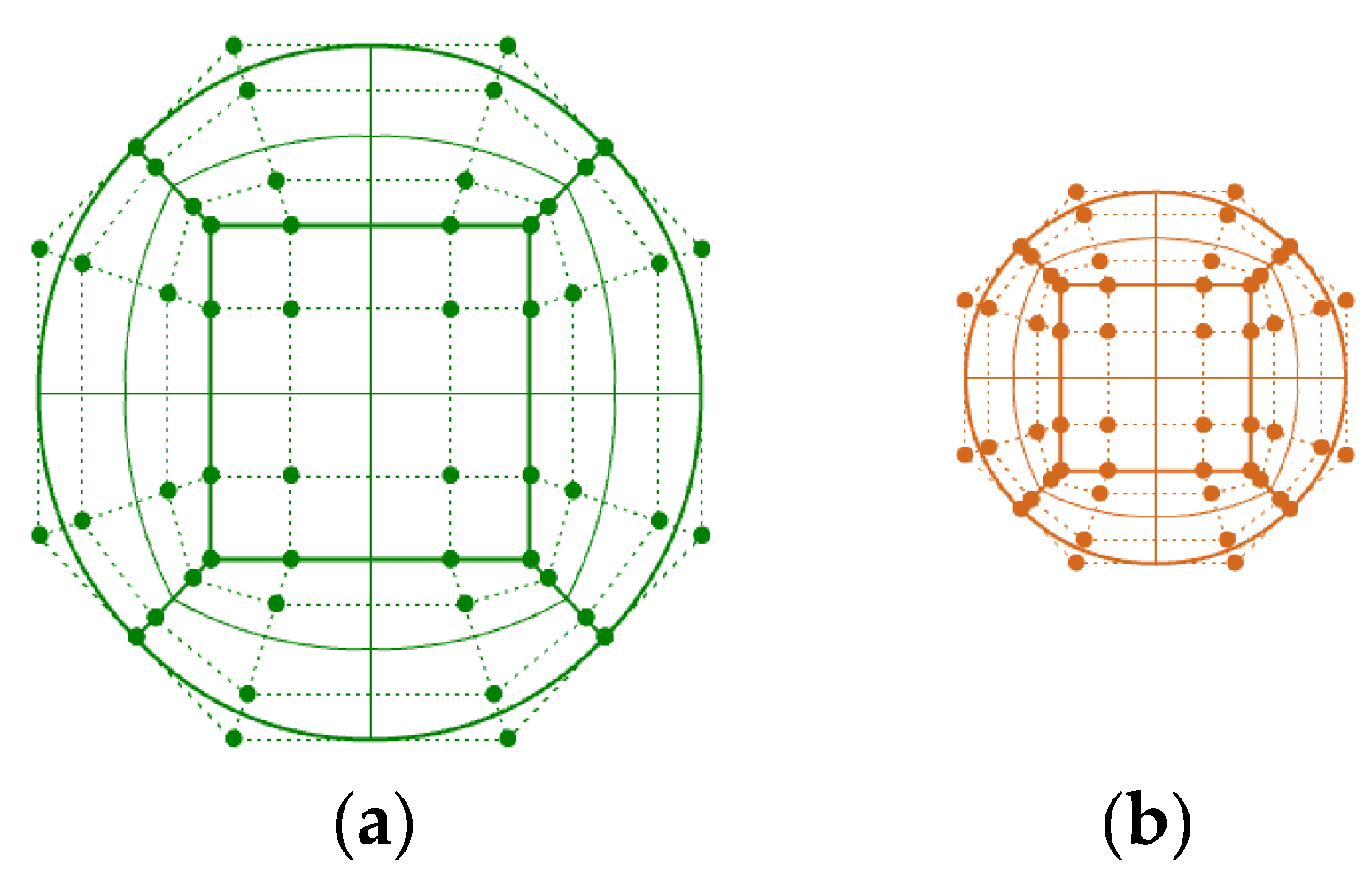
The first step of isogeometric analysis is to input the geometric model. For the cycloid drive mechanism analyzed in this paper, it is more difficult to express the cycloid gear with holes directly by NURBS modeling, so it is still necessary to carry out structured element division based on the cycloid gear NURBS surface established in the previous paper, and divide the output pin hole part of the cycloid gear into different NURBS slices before stitching. The quarter of the cycloid gear NURBS surface shown in Figure 14 is re-divided, with the order of the basis function in each NURBS slice set as second order and the surface containing four control points in each direction. According to the symmetry, the surfaces are arrayed and the coordinates of the overlapping boundary control points are changed to construct the initial NURBS tooth surface of the complete cycloid gear as shown in Figure 15a. The refined model is shown in Figure 15b, and the number of elements per surface sheet is 100. The pin tooth and output pin surfaces are constructed in the same way, while the cross section is divided into five NURBS slices for the subsequent application of boundary conditions, and their initial cross sections are shown in Figure 16. The same k-refinement is used, and each surface slice contains 100 elements after refinement, as shown in Figure 17.
The created NURBS geometry model is saved in IGES format for data storage and exchange, and then entered into the IGA contact analysis process. Define the material density of the cycloid gear, pin tooth and output pin as 7800 kg/m3, the modulus of elasticity as E = 210 GPA and Poisson’s ratio as 
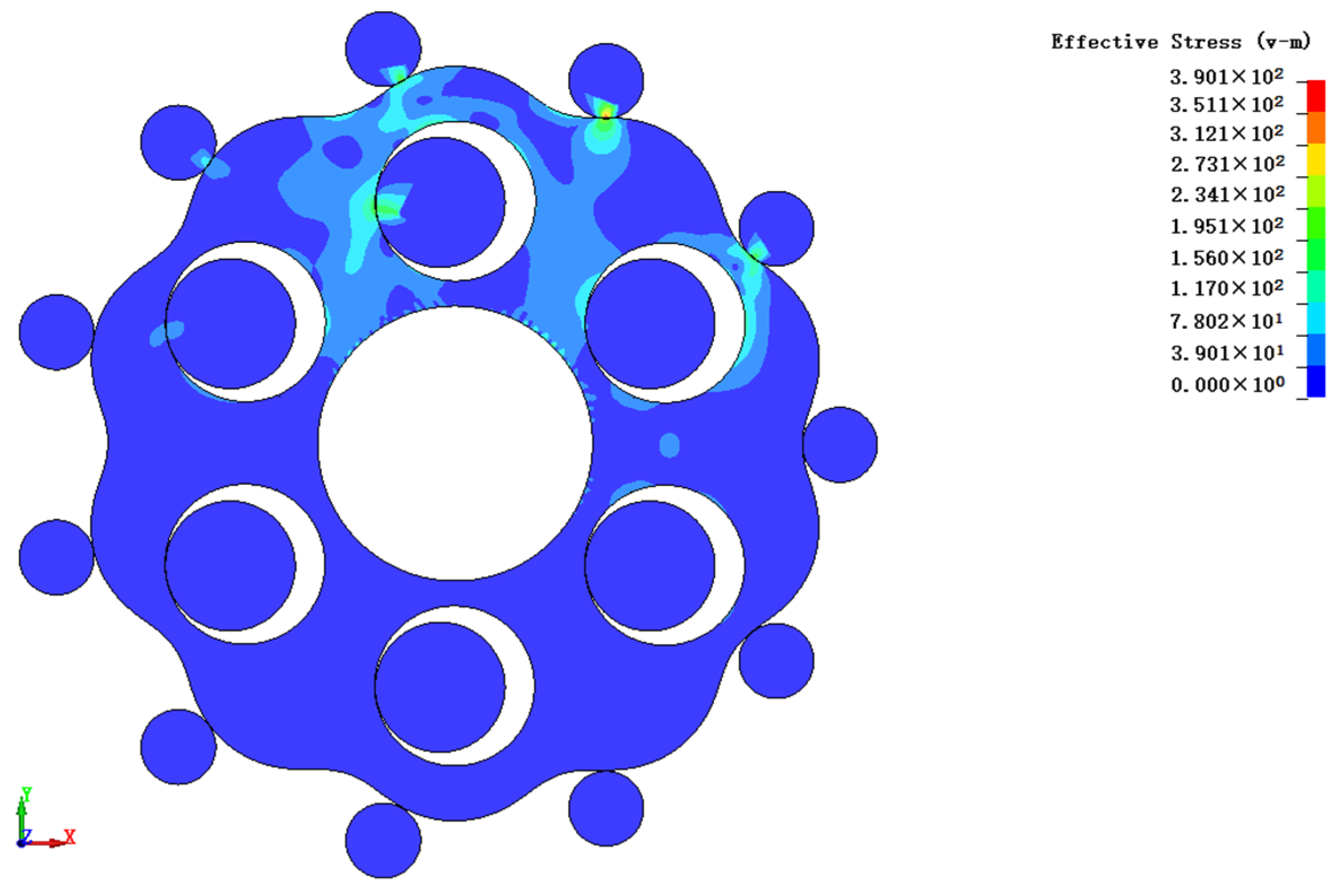
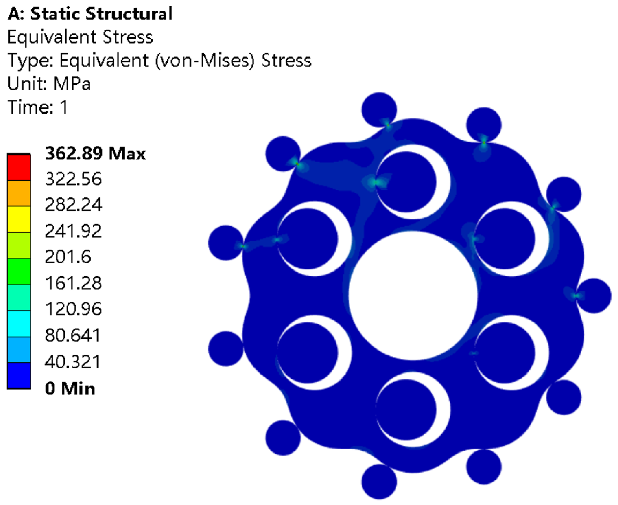
ν = 0.3. Fix the control points of the pin tooth and output pin in the central NURBS slice and constrain all their degrees of freedom. For the cycloid gear, the axial motion is constrained and the circumferential and tangential degrees of freedom are released. The control point around the cycloid gear center hole is coupled as a rigid node to which a clockwise torque of 100 N·mm is applied according to the mechanism transmission ratio calculation formula. For the meshing pair in which the contact element is handled in a face-to-face contact mode, the master-slave contact search algorithm is used, and the contact pair is set with the cycloid gear tooth face as the master contact face and the pin tooth and the output pin face as the slave contact surface. Traverse all NURBS elements with the set constraint conditions and contact settings and assemble the overall stiffness matrix, the solver uses LS-DYNA R13.0 to compute the contact stress nephogram of the cycloid pinwheel mechanism for three different input angles as shown in Figure 18.
According to the stress nephogram, the maximum stress occurs in tooth No. 3. The maximum stress contact tooth number is consistent with the theoretical contact analysis. From the color change of the contact surface, the stress trend is all from yellow-green to light blue. Observing the NURBS element on the contact pair with stress distribution, it is concluded that the number of contact stresses generated by the pin tooth, output pin and cycloid gear under this input angle is consistent with the theoretical analysis, and the stress area from the equal geometric analysis is consistent with the theoretical cycloid drive stress characteristics, and the IGA model is reasonably constructed, and the maximum contact stress is 390.1 MPA.

4. Results and Discussion

4.1. Contact Analysis of Cycloidal Gear and Pins by FEA

Using the commercial FEM software Ansys workbench 2020 R2, the contact stresses of the cycloid pinwheel drive are solved to facilitate comparison with subsequent geometric results. According to the characteristics of the mechanism, the 2D plane stress static analysis module is used to extract the cycloid gear–pin tooth–output pin plane. Using the same material parameters, boundary conditions, and contact pair settings as the isogeometric method, the crank input angle is solved at 0 degrees, and the solution time and load step are defined and solved using the direct solver, resulting in the contact stress nephogram of the component as shown in Figure 19.
It can be observed that the contact pin teeth are No. 2–6 and the contact output pins are No. 1–3. The number of stressed pin teeth and output pins is also in accordance with the theory of stress area within 0 to 180 degrees in the crank input direction under the ideal tooth profile. The maximum contact stress of the pin is 362.89 MPA.

4.2. Comparison of Contact Force from IGA and FEA

Since the contact stress distribution of the pin tooth and output pin derived from the two methods are the same as the theoretical stress areas, they are consistent with the force characteristics of the cycloid pinwheel and prove that the analytical model design is reasonable. The results of isogeometric analysis, finite element results and theoretical solution results are compared, and the values of maximum contact stress are listed in Table 3.
From the table, it can be seen that the maximum stress error out of the isogeometric analysis of the cycloid drive is smaller than ones from the finite element method, and the error of the isogeometric method compared to the theoretical solution is all between 1% and 2%. The contact force of the pin, output pin, and cycloid gear in the stressed area is extracted and compared with the theoretical values, as shown in Figure 20. The error comparisons are shown in Table 4 and Table 5.
From the graph, the pin tooth contact force FN and the output-pin contact force FK solved via isogeometric analysis are smaller than the finite element, and the error of the isogeometric contact force solved value is about 3% compared with the theoretical value. In the isogeometric contact analysis, the mesh deformation due to the lack of accuracy of the geometric model contour surface can be improved to some extent because of the high-order continuity property of the NURBS basis function. Thus, it avoids the jump of the contact force value of the finite element method, which differs too much from the theoretical value due to the occurrence of slippage or separation phenomenon when analyzing the contact pair. By comparing the analysis results of the two methods, the principle that the contact force calculation of isogeometric analysis is more accurate due to the higher accuracy of the NURBS surface boundary is verified.
The results of isogeometry and finite element were compared under the same number of elements divided by the model surface to verify the accuracy of the isogeometry analysis method in the cycloid gear tooth surface with fewer elements, and the contact stress of the most stressed gear tooth was selected to compare the results.
A comparison of results can be made when viewing geometric and finite element results under a different number of units of model surface division to verify the accuracy of geometric analysis method under less units of cycloid pinwheel tooth surface and to select the contact stress of the pin with the largest force. With the crankshaft input angle of 0 degrees, the cycloid gear and the pin will be arranged with a different number of NURBS units for each NURBS tooth surface. The mechanism of the NURBS model is shown in Figure 21. In the FEA model with the same number of elements as the control group, the comparison of the IGA method and the finite element method for the change of the maximum contact stress regularity with different numbers of element on the contact tooth surface of the cycloid gear is shown in Figure 22. The comparison of the maximum stress with the theoretical value of the calculation error is shown in Table 6.
Figure 22 shows that the calculated values of both the isogeometric method and the finite element method can converge to the accurate value when the number of elements is increasing, but the isogeometric method can achieve a relatively high accuracy when the number of elements is small. From the specific error comparison in Table 6, it can be seen that the error of the finite element method is larger when the distribution of elements on the tooth surface is small. The error in the isogeometric method is only 8.8% when only 10 × 10 elements are arranged on the surface piece in contact, while the error in the finite element method reaches about 40%. Moreover, when the number of surface elements at the contact position is increased to 25 × 25, the finite element result error is still 10%, while the isogeometric result has already converged to a slight error of 2.5%. It is because the mesh divided by the finite element method consists of interpolation for the Lagrangian function, which makes the model boundary continuity low. When the cycloid gear tooth contact area is larger, it will cause the two element boundaries to enter the contact calculation simultaneously, equivalent to the increase of contact area, resulting in the increase of contact force error. However, the isogeometric method still has a high accuracy when the number of meshes is small and the errors are all within 10% because the stresses between the adjacent NURBS patches are continuous, based on the higher-order continuous nature of the basis function. As a result, the isogeometric analysis method is able to produce contact analysis results with high-accuracy with a small number of surface elements. It avoids the complex meshing process while ensuring accuracy, resulting in a significant reduction in the computational degrees of freedom and a significant advantage over the traditional finite element method in terms of result accuracy.
The traditional finite element method is required to refine a high-density mesh for contact analysis to obtain an approximate theoretical solution. However, as the mesh increases, the meshing time increases and consumes considerable solving time and computer resources. In contrast, isogeometric analysis can obtain more accurate solutions with fewer NURBS elements, and the essence of isogeometric analysis is to analyze the NURBS model elements directly without the requirement for the finite element method of mesh reconstruction to approximate the model boundary. Thus, avoiding the complex mesh division and approximation process in finite element, so it will greatly reduce the analysis time and save computational costs. A comparison of the analysis time of the cycloid drive mechanism converging to the exact solution under the same computer hardware conditions is shown in Table 7.
The comparison of the solution time shows that isogeometry is faster than the finite element method under the same conditions, thereby verifying the high-efficiency of isogeometry in contact analysis. Therefore, the isogeometric analysis method is more suitable than the finite element method for the analysis of the contact problems of cycloid pinwheel transmission. It can significantly improve the computational efficiency and provide guidance for the high-performance design and manufacturing of cycloid pinwheel transmission.

5. Conclusions

In this paper, the isogeometric analysis method was applied to the contact analysis of the cycloid drive meshing pair, and the static force analysis model of the cycloid drive was established. The results of the isogeometric analysis were compared with the theoretical values and the calculated ones from the finite element software. The main conclusion is as follows:
(1)
The isogeometric analysis uses NURBS basis functions to construct the cycloid pinwheel transmission model. Its higher order continuity can accurately describe the contact boundary of the cycloid gear, which gives more accurate results of the contact force of the meshing pair compared to the finite element method;
(2)
The isogeometric analysis avoids the remeshing of the model in the finite element analysis, and instead uses a parametric unified NURBS model at all stages of the calculation, which gives the method high accuracy even with a small number of elements in the model;
(3)
The isogeometric analysis substantially saves the solution time and cost, and significantly improves the efficiency of cycloid pinwheel contact analysis.
In the future, the 3D NURBS model of the cycloid drive mechanism can be further constructed and isogeometric contact analysis will be applied to simulate the dynamic contact force performance of each component in actual operations.

Author Contributions

Conceptualization, C.G.; Methodology & Software, Y.S. and B.Z.; Validation, P.G.; Writing—review & editing, K.Z. and Y.L. All authors have read and agreed to the published version of the manuscript.

Funding

This work was funded by the Youth Innovation Team of Shaanxi Universities: Metal Corrosion Protection and Surface Engineering Technology, Research and application of key component materials for engines, Shaanxi Provincial Natural Science Foundation (2023-JC-YB-380), Shaanxi Provincial Key Research and Development Project (2019ZDLGY05-09), Local Serving Special Scientific Research Pro-jects of Shaanxi Provincial Department of Education (19JC022).

Institutional Review Board Statement

Not applicable.

Informed Consent Statement

Not applicable.

Data Availability Statement

Data are contained within the article.

Conflicts of Interest

The authors declare no conflict of interest.

References

  1. Qiao, X.T.; Zhang, L.B.; Yan, C.F.; Wang, C.L.; Wang, W.G.; Zhang, L.Y. Analysis on Development Status of RV Reducer Used in Industrial Robot in China. J. Mech. Strength 2019, 41, 1486–1492. [Google Scholar]
  2. Song, S. Industrial robot RV reducer key components manufacturing and thinking about the development of China’s precision machine tools. Met. Work. (Met. Cut.) 2015, 08, 34–36. [Google Scholar]
  3. Li, X. Benchmarking Research on Patent Technology of RV Reducer of Robot in China and Japan from the Perspective of Chinese Patent Intelligence. J. Libr. Inf. Sci. Agric. 2021, 33, 5–11. [Google Scholar]
  4. Duc, A.P.; Joon, H.A. Rigid Precision Reducers for Machining Industrial Robots. Int. J. Precis. Eng. Manuf. 2021, 22, 1469–1486. [Google Scholar]
  5. Thube, S.V.; Bobak, T.R. Dynamic Analysis of a Cycloidal Gearbox Using Finite Element Method; AGMA Technical Paper; American Gear Manufacturers Association: Alexandria, VA, USA, 2012; pp. 1–13. [Google Scholar]
  6. Blagojevic, M.; Marjanovic, N.; Djordjevic, Z.; Stojanovic, B.; Disic, A. A new design of a two-stage cycloidal speed reducer. J. Mech. Des. 2011, 133, 085001. [Google Scholar] [CrossRef]
  7. Hsieh, C.F. Traditional versus improved designs for cycloidal speed reducers with a small tooth difference: The effect on dynamics. Mech. Mach. Theory 2015, 86, 15–35. [Google Scholar] [CrossRef]
  8. Hsieh, C.F.; Fuentes-Aznar, A. Performance prediction method of cycloidal speed reducers. J. Braz. Soc. Mech. Sci. Eng. 2019, 41, 186. [Google Scholar] [CrossRef]
  9. He, W.D.; Zhang, Z.Y.; Wu, X.H. Study of Time Varying Meshing Stiffness of RV Drive based on ANSYS. J. Dalian Jiaotong Univ. 2017, 38, 55–57. [Google Scholar]
  10. Ahn, H.; Choi, M.B.; Lee, H.Y.; Pham, A.D. Impact Analysis of Tolerance and Contact Friction on a RV Reducer using FE Method. Int. J. Precis. Eng. Manuf. 2021, 22, 1285–1292. [Google Scholar] [CrossRef]
  11. Zhang, Y.M.; Li, L.S.; Ji, S.T. Influence of the eccentricity of cycloid-pin transmission mechanism on bearing capacity. J. Harbin Eng. Univ. 2022, 43, 873–881. [Google Scholar]
  12. Hu, H.; Batou, A.; Ouyang, H. An Isogeometric analysis based method for frictional elastic contact problems with randomly rough surfaces. Comput. Methods Appl. Mech. Eng. 2022, 394, 114865. [Google Scholar] [CrossRef]
  13. Hughs TJ, R.; Cottrell, J.A.; Bazilevs, Y. Isogeometric analysis: CAD, finite elements, NURBS, exact geometry and mesh refinement. Comput. Methods Appl. Mech. Eng. 2005, 194, 4135–4195. [Google Scholar] [CrossRef]
  14. Bazilevs, Y.; Beirao da Veiga, L.; Cottrell, J.A.; Hughes, T.J.; Sangalli, G. Isogeometric analysis: Approximation, stability and error estimates for h-refined meshes. Math. Models Methods Appl. Sci. 2006, 16, 1031–1090. [Google Scholar] [CrossRef]
  15. Agrawal, V.; Gautam, S.S. IGA: A simplified introduction and implementation details for finite element users. J. Inst. Eng. India Ser. C 2019, 100, 561–585. [Google Scholar] [CrossRef]
  16. Lu, J. Isogeometric contact analysis: Geometric basis and formulation for frictionless contact. Comput. Methods Appl. Mech. Eng. 2011, 200, 726–741. [Google Scholar] [CrossRef]
  17. Xu, H.; Yang, G.L.; Zheng, J.G.; Ge, J. Research of the Isogeometric Analysis of Gear Frictionless Contact. J. Mech. Transm. 2015, 39, 30–32. [Google Scholar]
  18. Chen, L.; Hao, C.J.; Wang, C.H.; Feng, W.B.; Yang, Y.M. Isogeometric analysis of gear contact for single tooth meshing. J. Mech. Eng. 2021, 57, 107–115. [Google Scholar]
  19. Xue, Y.T.; Zhao, G.; Wang, A.Z.; Chuan, H.E. Isogeometric analysis of bending strength of spur gear. J. Graph. 2022, 43, 79–84. [Google Scholar]
  20. Greco, F.; Rosolen, A.; Coox, L.; Desmet, W. Contact mechanics with maximum-entropy meshfree approximants blended with Isogeometric analysis on the boundary. Comput. Struct. 2017, 182, 165–175. [Google Scholar] [CrossRef]
  21. Rückwald, T.; Held, A.; Seifried, R. Flexible multibody impact simulations based on the isogeometric analysis approach. Multibody Syst. Dyn. 2022, 54, 75–95. [Google Scholar] [CrossRef]
  22. Xu, L.X.; Zhong, J.L.; Li, Y.; Chang, L. Design and dynamic transmission error analysis of a new type of cycloidal-pin reducer with a rotatable output-pin mechanism. Mech. Mach. Theory 2023, 181, 105218. [Google Scholar] [CrossRef]
  23. Leidingera, L.F.; Breitenbergera, M.; Bauera, A.M.; Hartmann, S.; Wüchner, R.; Bletzinger, K.U.; Duddeck, F.; Song, L. Explicit dynamic isogeometric B-Rep analysis of penalty-coupled trimmed NURBS shells. Comput. Methods Appl. Mech. Eng. 2019, 351, 891–927. [Google Scholar] [CrossRef]
  24. Remzija, C.; Lisbeth, F.; Torben, O.; Johansen, P. An Isogeometric Analysis Approach to Kinematics of Spatial Rigid Multibody Systems with Imperfect Joints. Model. Identif. Control. 2020, 41, 29–40. [Google Scholar]
Figure 1. Model of single tooth surface of cycloidal gear: (a) initial surface; (b) refined surface.
Coatings 13 02029 g001
Figure 2. Complete cycloid gear model.
Coatings 13 02029 g002
Figure 3. Boundary comparison: (a) NURBS surface boundary; (b) Lagrange mesh of FEM.
Coatings 13 02029 g003
Figure 4. Comparison of tooth profile.
Coatings 13 02029 g004
Figure 5. Tooth profile deviation amount.
Coatings 13 02029 g005
Figure 6. Schematic diagram of the model of cycloid pinwheel transmission.
Coatings 13 02029 g006
Figure 7. Analysis of the applied force on the cycloid gear at 45 degrees of input angles.
Coatings 13 02029 g007
Figure 8. Force diagram of input crank at 45 degrees of input angles.
Coatings 13 02029 g008
Figure 9. Pin tooth contact force distribution.
Coatings 13 02029 g009
Figure 10. Output-pin contact force distribution.
Coatings 13 02029 g010
Figure 11. Amplitude of crank contact force at different input angles.
Coatings 13 02029 g011
Figure 12. Crank contact force components at different input angles.
Coatings 13 02029 g012
Figure 13. Isogeometric contact analysis flow.
Coatings 13 02029 g013
Figure 14. Quarter of the cycloid gear.
Coatings 13 02029 g014
Figure 15. Complete tooth surface of the cycloidal gear: (a) Before refinement; (b) After refinement.
Coatings 13 02029 g015
Figure 16. Output pin and pin tooth NURBS section: (a) Output pin; (b) Pin tooth.
Coatings 13 02029 g016
Figure 17. NURBS section after refinement: (a) Output pin (b) Pin tooth.
Coatings 13 02029 g017
Figure 18. IGA contact stress nephogram.
Coatings 13 02029 g018
Figure 19. Finite element pin tooth contact stress diagram.
Coatings 13 02029 g019
Figure 20. Comparison of IGA and FEM contact force: (a) comparison of pin tooth contact force; (b) comparison of output-pin contact force.
Coatings 13 02029 g020
Figure 21. IGA model with different NURBS elements for tooth face. (a) Number of tooth flap elements 5 × 5, (b) Number of tooth flap elements 10 × 10, (c) Number of tooth flap elements 15 × 15, (d) Number of tooth flap elements 20 × 20, (e) Number of tooth surface elements 25 × 25, (f) Number of tooth surface elements 30 × 30.
Coatings 13 02029 g021
Figure 22. Maximum contact stress versus element density.
Coatings 13 02029 g022
Table 1. Design parameters of cycloid drive.
Design ParametersValue
Number of cycloid teeth10
Number of pin teeth11
Pin tooth radius3 mm
Pin tooth distribution radius32 mm
Output pin radius6.4 mm
Radius of output pin distribution19.4 mm
Eccentric distance1.2 mm
Table 2. Comparison of tooth profile points.
Numberxi (mm)yi (mm)yi′ (mm)fy (mm)
122.49−16.3403−16.35015.99 × 10−4
222.63−16.1524−16.15293.2 × 10−5
322.77−15.9712−15.97183.7 × 10−5
422.82−15.8054−15.80322.02 × 10−4
Table 3. Comparison of contact stress results for the pin teeth of the cycloid gear.
MethodMaximum Stress Value/MPAError/%
Theoretics395.80/
IGA390.101.26
FEM362.898.11
Table 4. Comparison of contact force error of pin tooth.
Contact Tooth NumberFEM/%IGA/%
28.43.1
39.32.3
412.53.7
518.24.2
610.83.2
Table 5. Comparison of contact force error of output pin.
Contact Tooth NumberFEM/%IGA/%
14.61.7
29.32.3
311.22.9
Table 6. Comparison of errors between IGA and finite element results at different element numbers.
Element NumberIGA/%FEM/%
5 × 561.511.6
10 × 1041.18.8
15 × 1525.16.3
20 × 2013.94.5
25 × 2510.12.5
30 × 308.71.2
Table 7. Comparison of total time spent on analysis and calculation.
MethodMesh Division Time/minMesh Division Time/minTotal Time/min
FEM124759
IGA/66
Disclaimer/Publisher’s Note: The statements, opinions and data contained in all publications are solely those of the individual author(s) and contributor(s) and not of MDPI and/or the editor(s). MDPI and/or the editor(s) disclaim responsibility for any injury to people or property resulting from any ideas, methods, instructions or products referred to in the content.

