Article

Wear Evolution on PVD Coated Cutting Tool Flank and Rake Explained Considering Stress, Strain and Strain-Rate Dependent Material Properties

by
Antonios Bouzakis
1,
Georgios Skordaris
2,
Emmanouil Bouzakis
3,
Konstantinos-Dionysios Bouzakis
2,* and
Dimitrios Tsakalidis
2
1
Impact-BZ, London SW11 5QL, UK
2
Laboratory for Machine Tools and Manufacturing Engineering, Mechanical Engineering Department, Aristotle University of Thessaloniki, 54124 Thessaloniki, Greece
3
Department of Mechanical Engineering, University of Thessaly, 38334 Volos, Greece
*
Author to whom correspondence should be addressed.
Coatings 2023, 13(12), 1982; https://doi.org/10.3390/coatings13121982
Submission received: 5 October 2023 / Revised: 14 November 2023 / Accepted: 15 November 2023 / Published: 22 November 2023

Abstract

:
Impact loads developed on a tool cutting edge when milling into a workpiece material are prevailing metrics for explaining coating fatigue failure and the subsequent tool-wear evolution. For predicting related stress and strain fields in the compound coating-substrate, stress, strain, and strain-rate, dependent material properties are required. The attainment of such data is briefly described in the paper. Considering these data, the occurring strains in the cutting edge at various entry impact durations, i.e., strain rates, were calculated and compared with fatigue-critical strains. In this way, the wear phenomena causing the coating failure on the flank and rake during milling were clarified. The attained results were also correlated to corresponding ones in turning, where the dynamic loads of the cutting edge are comparably negligible. The conducted investigations showed that the fatigue-critical strains strongly diminish, when the relevant strain rates increase; thus, leading to a remarkable tool-life reduction. This happens, because the increase of the strain-rate restricts the time for the dislocations movements; thus, regions with stress concentrations occur, deteriorating the material ductility, increasing its brittleness, and diminishing the fatigue critical strains. In cutting operations, where the coating fatigue is the main wear factor, the tool-life can be predicted considering these phenomena. In the paper, relevant experimental analytical procedures are introduced.

Graphical Abstract

1. Introduction

Nowadays, coated tools are usually applied in manufacturing procedures with material removal, rendering the employment of uncoated ones as an exception [1]. Most of the cutting tools are coated by physical vapor deposition (PVD) or chemical vapor deposition (CVD) processes. PVD covers a broad family of vacuum coating processes in which the employed material is physically removed from a source by evaporation via arcing or sputtering [1]. Then, it is transported by the energy of the vapor particles and condenses as a film on the surfaces of the parts under a vacuum. Chemical compounds are deposited by either using a similar source material, or by introducing reactive gases (nitrogen, oxygen, or simple hydrocarbons) containing the desired reactants, thus, reacting with metal(s) from the PVD source.
Such produced coated tools possess a compound material structure consisting of the substrate material; for example, a cemented carbide covered with a hard, anti-friction, chemically inert, and thermal isolating layer approximately one to a few micrometers thick. These coatings have high mechanical properties which diminish interactions between tool and chip and improve wear-resistance in a wide cutting temperature range [2,3,4,5,6,7,8,9,10,11]. Enhanced coating properties can also be attained via the plasma energy increase and optimization of the plasma kinematics in the PVD vacuum chamber [12,13,14,15].
In cutting processes with interrupted chip formation, as in milling, the coating fatigue failure is the prevailing wear phenomenon significantly restricting tool life [1,3,16,17]. This phenomenon is affected by the magnitude and duration of the impact load on the cutting edge during its repetitive entries into the workpiece material. Herein, if the impact load duration reduces, the developed strain-rates increase, therefore diminishing the available deformation time and under certain critical values, the material deformation itself, and thus, the occurring contact area between the indenter and tested surface [1,17,18,19,20,21]. Hence, keeping the impact load constant, the surface-specific load grows with the relevant coating wear evolution too. In the paper, the experimental–analytical quantification of this phenomenon is briefly described, and an applied example in milling will be introduced. This innovative procedure can be used to predict the tool life when coating fatigue is the prevailing factor for the wear evolution. Moreover, the latter procedures can be also applied to check the effect of the cutting depth to tool diameter ratio as well as of the cutting conditions on the tool life, thus, rendering their optimization possible.

2. Experimental and Computational Methods Applied to Detect Static and Dynamic Material Properties

2.1. Procedures to Attaining Stress, Strain, and Strain-Rate Material Data

The kinematics of the impact loading of a coated surface can be simulated by the repetitive impacts of a cemented carbide ball indenter on the coated specimen (see Figure 1) [1,22,23,24]. In this experimental procedure, the substrate commonly deforms elastically and plastically, and the coating, elastically. Moreover, the impact test at elevated temperatures is a convenient experimental method for characterizing coating fatigue up to a temperature of approximately 500 °C [1]. Usually, the ball-indenter material is cemented carbide. Its elastic and potential plastic deformation, according to the impact load magnitude, is determined using an FEM simulation of the ball indenter’s penetration into the coated specimen, as described in the following figure.
Devices developed to carry out this process at various impact loads and durations are exhibited in Figure 2. The motion data of the ball indenter (force magnitude and impact duration) are adjusted by the control units of the impact-testing instruments illustrated in Figure 2. The adjustment of impact duration is necessary, among other factors, to simulate the entry duration on the cutting edge during milling under various process conditions. With the aid of the electromagnetic impact tester, impact times less than 1 ms can be realized; whereas using the piezoelectric impact tester, impact times can be selectively achieved to be longer than 1 ms up to a few tens of ms. The adjusted impact force grows almost linearly up to a maximum value. This time course of the impact force remains constant in the sequential impacts. By means of the micro-indenter, practically quasistatic loads of several seconds duration up to the desired maximum force can be adjusted. The introduced impact devices are manufactured by Impact BZ Ltd. (London, UK) [25].
Depending on the impact load, the number of impacts and impact duration, a coating failure may occur. In the demonstrated investigations in Figure 3, an electromagnetic impact tester was used at ambient temperature and an impact time duration td of approximately 0.45 ms, as shown in Figure 3a. According to the demonstrated results, the coating withstood one million impacts without damage up to an impact force of 900 N (see Figure 3b).
At impact loads equal or larger than 900 N, the coating fails at less than one million impacts, and is partially removed. The developed imprint areas are apparent in the photos of Figure 3b. The number of impacts leading to coating failure onset reduces exponentially with the impact force increase, as schematically depicted in the Woehler-like diagram in Figure 3b. At impact times IT larger than 0.45 ms, the critical impact force increases, as in the following explanation. The results exhibited in Figure 3 were attained via investigations conducted for the needs of the present paper. Numerous publications concerning the development and applications of the repetitive impact test technique are mentioned in [1]. Thus, the Woehler-like curve is associated with a certain strain rate. This curve has a practical importance, since with its aid, the number of repetitive impacts leading to coating fatigue failure at this strain rate can be predicted depending on the repetitive load magnitude. Examples of the relevant application are demonstrated in the next sections.
For calculating the specimen and ball indenter surface responses as well as the relevant stress, strain, and strain-rate fields during the impact test loading and relaxation phases, the axisymmetric FE model was used, as presented in Figure 4 (ITe/FEMS, Impact Test FEM Simulation) [1]. This model was developed employing the ANSYS software package. Appropriate contact elements in normal y and tangential x directions were applied to consider the adhesion of a well-adherent coating on its substrate. To facilitate such calculations, stress, strain, and strain-rate dependent constitutive flow curves for the used cemented carbide substrate and coating are required.

2.2. The Applied Cemented Carbide and TiAlN Coating and the Determination of Their Constitutive Laws under Static Loads

In the described investigations, the selected material for the ball indenter and specimen substrate was a fine-structured cemented carbide of SPGN/HW K05 ISO specifications with an average grain size of 1–1.3 μm.
Furthermore, a (Ti35Al65)N coating, of approximately 4 μm thickness, was deposited on the cemented carbide inserts using high-ionization pulsing (HIP) and high-ionization magnetron sputtering (HIS) PVD process [1]. Using this method, a crystalline sub-micron film microstructure was obtained. The applied PVD films were produced using an industrial CC800/9 HPPMS coating unit of CemeCon AG. Before the coating deposition, the specimen surfaces were appropriately pretreated for enhancing the coating adhesion (superficial Co reduction, ion etching). The coating adhesion was checked via inclined impact tests, as [1] described, and was assessed as very good. Due to the used HPPMS coating procedure, an almost constant coating thickness of ca. 4 μm along the cutting edge was achieved. The uniform thickness distribution on the tool rake and flank was checked in all specimen cases via a cratering test by means of a CemeCon device (caloten test). In some specimen cases, the uniform coating thickness distribution along the cutting edge was also ascertained through cross sections of the cutting edge and observations with the aid of a metallographic microscope.
To determine the coating and the cemented carbide’s mechanical properties, nanoindentations at ambient temperatures at quasi-static loads were carried out using a FISCHERSCOPE H100 device. At higher temperatures, a micro-indenter by Micro-Materials Ltd. (Wrexham, UK) was used. The measurements were repeated until the average of the recorded curves representing the course of the indentation depth versus the indentation load was stabilized. Herein, the relevant number of measurements depends on the surface roughness [1].
The obtained nanoindentation diagrams at ambient temperatures are presented in Figure 5a. Relevant diagrams at elevated temperatures were introduced in [17]. Based on these diagrams, the stress–strain curves of the substrate and coating were determined by an FEM supported evaluation of the nanoindentation results, as also described in [17]. The calculated stress–strain curves, the Young’s modulus, the yield and rupture stress of the coating and its substrate are displayed in Figure 5b. Herein, the coating yield stress SY of 6.3 GPa corresponds to an equivalent strain of about 0.012. The attained coating’s mechanical and fatigue properties were almost invariant up to the mentioned coating yield strain of approximately 0.012, up to a temperature of ca. 400 °C [16]. The cemented carbide related properties are less than 5% up to the same temperature [26].

3. Determination of Fatigue Critical Stress and Strain-Rate Data of Substrate and Coating

3.1. Cemented Carbide Substrate

Data for the stress–strain and strain-rate curves up to strain-rates of approximately 200 s−1 for the used cemented carbide substrate were produced with the aid of the developed experimental–analytical method presented in [27]. A strain rate of 200 s−1 approximately corresponds to an impact time of 0.1 ms. In this way, a wide range of milling cases can be handled, as exhibited in Section 4. Using this method, the remaining imprints on cemented carbide surfaces at various impact load durations and magnitudes were registered by a confocal microscope by Nano Focus Ltd. and evaluated via a developed FEM supported procedure explained in [27].
Noteworthy for the case of loading at a strain rate of 200 s−1, the dynamic von Mises flow stress increase of the tested cemented carbide material amounts to 51%, compared to the corresponding static stress (see Figure 6). Consequently, when decreasing the impact time at a constant load, the developed strains and stresses increase as already mentioned. At these dynamic strain-rates, inertial effects start changing the homogeneous stress state in quasistatic loading cases. In this way, movements of dislocations are blocked and regions with stress concentrations occur, thus deteriorating the material ductility and increasing its brittleness. At strains larger than approximately 0.02, the material cohesion is exhausted, and it deforms without resisting. Therefore, the cemented carbide’s constitutive laws over the mentioned strain become horizontal. It must be pointed out, that the described method in [27] cannot be used to attain relevant material data for PVD coatings due to their restricted thickness compared to the substrate dimensions, as explained in the next section.

3.2. TiAlN Coating on Cemented Carbide Substrate

PVD coatings commonly have a thickness of only a few microns and are deposited on substrates with significantly larger dimensions. Thus, the coating deformation magnitude is practically imposed by the strains developed in the substrate. Herein, potential coating strains induced by dynamic phenomena of the coating material itself can be considered as negligible compared to those caused by the substrate deformation. Hence, if the strain–strain-rate dependency of the substrate material is available, the related coating deformation at various strain rates can be determined based on the coating static constitutive law and the substrate relevant dynamic data [27]. In these calculations, according to the impact time, the appropriate substrate material properties illustrated in Figure 6 must be employed.
Relevant calculation examples at impact times of 0.45 ms and larger than 10 ms are demonstrated in Figure 7. The maximum stress and strain fields during the loading phase at an impact force of 1500 N were determined. Due to material hardening when the strain rate increases, i.e., when the impact time IT decreases, the developed maximum stress in the substrate is larger, as already explained. According to the coating constitutive law (see Figure 5b), strains less than the yield εy of approximately 12 × 10−3 can be considered as safe since they do not cause a plastic deformation. However, a coating fatigue failure after one million impacts may occur at significantly lower strains than the yield one depending on the strain rate [21].
The presented results in Figure 8 ascertain this statement. The horizontal branch of the curve in the plot in this figure indicates the fatigue endurance forces at various impact times ITs. A fatigue damage criterion is considered as a coating failure depth CFD of 0.5 μm over the remaining coating imprint depth after 104 impacts, due mainly to plastic substrate deformation. The imprint geometries, demonstrated in the upper part of Figure 8, were measured using a confocal microscope by Nano Focus Ltd. For example, at an impact time of 0.45 ms, the fatigue critical force for 106 impacts amounts to about 900 N. The fatigue critical forces correspond to maximum stress, strain, and strain-rate of the related fields which were predicted by means of the previously described FEM simulation of the impact test. These stress, strain, and strain-rates are considered as fatigue critical ones at the corresponding impact times IT, i.e., strain rates. Impact forces imposing strains larger than the fatigue critical one at a certain strain rate cause micro-cracks in the coating structure. Through their propagation, coating fractures occur after a certain number of impacts according to the inclination of the Woehler-like curve.
Using the previously described analytical–experimental procedure, the dependency between the coating fatigue critical equivalent strain and strain-rate, as well as impact time IT, can be predicted. Such a dependency is exhibited in Figure 9. This diagram will be considered to explain coating fatigue failures in milling based on coating and substrate stress, strain, and strain-rate material data.

4. Experimental and Computational Details Related to the Conducted Milling Investigations

The performed wear-investigations in milling were appropriately planned to attain various entry impact durations te. The parameter te is defined as the average time tc up to the development of the maximum strain in the coated cutting edge during its entry into the workpiece, as exhibited in Figure 10a. At a constant cutting speed, te depends mainly on the relation between the radial depth of cut a to tool diameter D (a/D ratio) [1]. For achieving various te in milling, D was held as a constant equal to 60 mm, and the depth of the cut was increased from 3 mm up to 51 mm. In this way, the a/D ratio grew from 5% up to 85% (see Figure 10a). Hence, it was possible to perform milling investigations at te from about 0.21 ms up to 4.5 ms, as illustrated in the table of Figure 10a. The latter impact time te values correspond to strain rates less than 200 s−1 (see Figure 6). The related cemented carbide constitutive law for a certain te is defined via interpolation between constitutive laws of neighboring impact times. The factor te in turning corresponds to the duration of one workpiece revolution, i.e., to the time of reaching the maximum undeformed chip thickness hcu of 0.12 mm.
The maximum calculated temperature in turning varies depending on the cutting speed as well as the location on the tool rake, as illustrated in Figure 11. The developed maximum temperatures in positions 1 and 2 amount to approximately 160 °C at a cutting speed of 100 m/min. Thus, exhibiting a constant course versus the cutting speed at a temperature of ca. 200 °C. On the other hand, at the indicated location 3, the coating thermal load is maximized, and the temperature has an increasing tendency versus the cutting speed, attaining the value of about 600 °C, at a cutting speed of 600 m/min. The temperatures are comparably lower in milling operations at the same cutting speed, depending on the undeformed chip length and the tool diameter to cutting depth ratio. The coating’s mechanical properties changes in the elasticity region of its constitutive law are negligible when the temperature increases [17]. As already mentioned, the attained coating mechanical and fatigue properties were almost invariant up to the coating yield strain of approximately 0.012 and temperatures less than ca. 400 °C [17]. The coating fatigue failure initiation in milling takes place at point 2 (rake begin), as the following elucidates.
The flank wear VB was measured after a certain numbers of cuts. Due to the variable undeformed chip length at the diverse depths of cut, the VB evolution was displayed in the following figures versus the accumulative tool life T and not versus the number of cuts. The metric T was calculated by means of the equation exhibited at the bottom of Figure 10a. The wear investigations in milling and turning were performed without coolant or lubricant.
The cutting speed was selected at 200 m/min. According to calculations using the DEFORM software illustrated in Figure 11, the developed maximum coating temperature at this cutting speed is less than 600 °C. At this temperature, the coating remains chemically inert and no diffusions among chip, coating and cemented carbide can take place. Hence, the wear evolution must be attributed mainly to coating fatigue failures in combination with coating and substrate abrasion.
The cutting force components were acquired using a piezoelectric instrument by KISTLER AG. The coating adhesion was examined via inclined impact tests using an impact tester by IMPACT-BZ Ltd (London, UK) and was assessed as very good [1].
Employing the same device, perpendicular impact tests were performed at an impact time of ca. 0.4 ms for establishing Woehler-like diagrams. The flank wear width VB was measured employing an optical microscope. The wear evolution on the tool rake was captured using the confocal microscope μSURF by NanoFocus AG (Oberhausen, Germany). Employing the software of this device, the rake geometry was recorded on sections perpendicular to the cutting edge at a VB of approximately 0.15 mm, as depicted in Figure 10b. The FEM calculations to determine the stress and strain fields in the compound coating-substrate were conducted employing the ANSYS software package (version 2021 R1). In the performed calculations, considering the previous explanations, the mechanical properties of the elastically deformed coating were in accordance to Figure 5b. On the other hand, the substrate data were predicted through interpolations between curves of neighboring strain rates (see Figure 6).

5. Results and Discussion

5.1. The Conducted Experimental Investigations

The flank wear width (VB) evolution versus the accumulative tool life T is illustrated in Figure 12. The tool life improvement up to VB of 0.15 mm (VB0.15) is apparent when increasing the cutting edge entry impact duration te. An accumulative tool life of approximately 20 min is reached at a te of 4.5 ms (see Figure 12). Considering related results introduced in [1], the tool life is already stabilized at te of around 1 ms. The reason for that will be explained in Section 5.3. In comparison, for turning, the obtained tool life is substantially longer, amounting to about 112 min. However, the estimated number of tool entries (NE) into the workpiece in turning associated with possible process breaks due to machine-tool adjustments, workpiece changes, inspections, etc., potentially summing up to a few hundred, is significantly less than the corresponding numbers in milling; which amounts to tens of thousands in all investigated cases (see Figure 12). Herein, the attained tool life of around 112 min is considered as unrealistic. Its reduction can be achieved via the cutting speed increase which is associated with a productivity improvement.
Furthermore, the wear status of the tool rake at a VB of 0.15 mm (VB0.15) on the flank is demonstrated in Figure 13, for various cutting edge entry impact durations te. The graphs in this figure illustrate the related worn rake-surface geometries, which are drawn according to the measurements on the sections AA near the cutting edge, as already described. The related measurement graphs are presented at the bottom of Figure 13.
In all demonstrated cases, the width of the revealed substrate area at the flank amounts to about 0.15 mm (VB0.15) due to coating removal. The widths of the worn rake regions are also indicated in Figure 13. Although the thermal and mechanical cutting loads are almost equal in all the investigated cases. In turning, which is associated with the longer te of 13.3 ms and the smaller NE, the obtained tool-life of up to VB0.15 is far longer, and the rake is less worn compared to all milling cases. In a comparably restricted rake area of ca. 15 μm from the instantaneous rake begin (see Figure 13), the coating wear depth is less than 2 μm, i.e., it still covers and protects the tool rake. In contrast, the rake wears out intensively in all milling cases. More specifically, the coating wear depth and width on the rake increases along with the reduction of te. At the shortest te of 0.21 ms, the rake wear width is maximized up to about 50 μm, and the substrate is revealed on the rake up to around 30 μm, far from the new instantaneous rake begin (see Figure 13). The shortening of te increases the strain rates during the tool entry into the workpiece and accelerates the coating fatigue failure initiation. The parameter te is strongly affected by the diminishing of the depth of cut to tool diameter ratio, as demonstrated in Figure 10a. Employing the experimental–analytical procedures described in the following, the influence of te on the tool life in milling can be accurately predicted.
The prevailing wear mechanism in turning is abrasion on both flank and rake, and no film fatigue failure is expected, as elaborated in the following sections. The coating abrasive wear is accelerated at the most wear endangered region of the flank end (F) towards the rake due to high-mechanical loads developing in this cutting edge region. However, in milling, an early coating failure occurs at the region of F caused by coating fatigue [1]. In the latter publication, it is stated that the substrate revelation on the flank results to a significant heat flow into the cutting edge. In this way, a substrate weakening, and subsequent intensive abrasion is induced at the beginning of the rake region (RB). The latter statement cannot be ascertained considering the superficial geometries of the worn rake presented in Figure 13. If the previous statement was valid, then the wear evolution at the beginning of the rake in turning might be more intensive compared to milling. This should happen since at almost the same cutting loads and flank wear (VB0.15), a significantly greater cutting heat amount was transferred into the cutting edge in turning, due to the longer tool life, and subsequently, the flank-workpiece contact time. In this way, a substantially more intense abrasive wear should develop on the tool rake in turning compared to milling. Since this is not the case, the intensive wear evolution on the rake in milling must be attributed mainly to coating fatigue failure and not to abrasion facilitated by rake softening.

5.2. The Conducted Theoretical Investigations

To theoretically clarify these mechanisms, the stress and strain fields occurring in the coating and its substrate during milling were determined. Relevant results concerning the developed strain fields are demonstrated in Figure 14. The related calculations were performed using an FE model of the cutting edge. In this model, the cutting force components Fc and Fκn were considered, as exhibited in Figure 14. These were measured in turning for the cutting conditions presented in Figure 10a. To define the loads on the superficial rake nodes of the cutting edge FE model, a triangular load distribution was assumed within the tool contact length with the chip (ccl).
The calculations were carried out using stress–strain data for the cemented carbide substrate associated with quasistatic loads, and moreover, with dynamic ones at a strain- rate of approximately 96 s−1 corresponding to te equal to 0.21 ms (see Figure 2 and Figure 3a). The corresponding stresses to the strains demonstrated in Figure 14 can be defined by implementing the coating stress–strain curve shown in Figure 6. The FE calculated coating strains revealed that their maximum values are slightly influenced by the strain-rate dependent substrate properties. More specifically, the maximum strains are equal to 11 × 10−3 and 10.9 × 10⁻³ for the material cases 1 and 2 accordingly (see Figure 14). However, due to the cemented carbide strengthening at higher strain-rates, larger substrate and coating regions are loaded higher, at the strain-rate of 96 s−1, compared to the quasistatic one of less than 3 s−1. For example, at the region of RB, the strain amounts to approximately 5 × 10⁻³ and 6 × 10⁻³ in the material cases 1 and 2 at strain-rates lower than 3 s−1 and 96 s−1, respectively. It must be noted that the developed coating strains can be compared with fatigue-critical ones at various strain rates, as explained in previous sections. In this way, as elucidated in the following, a prediction of the coating fatigue failure start, and thus, of the expected tool life can be obtained.

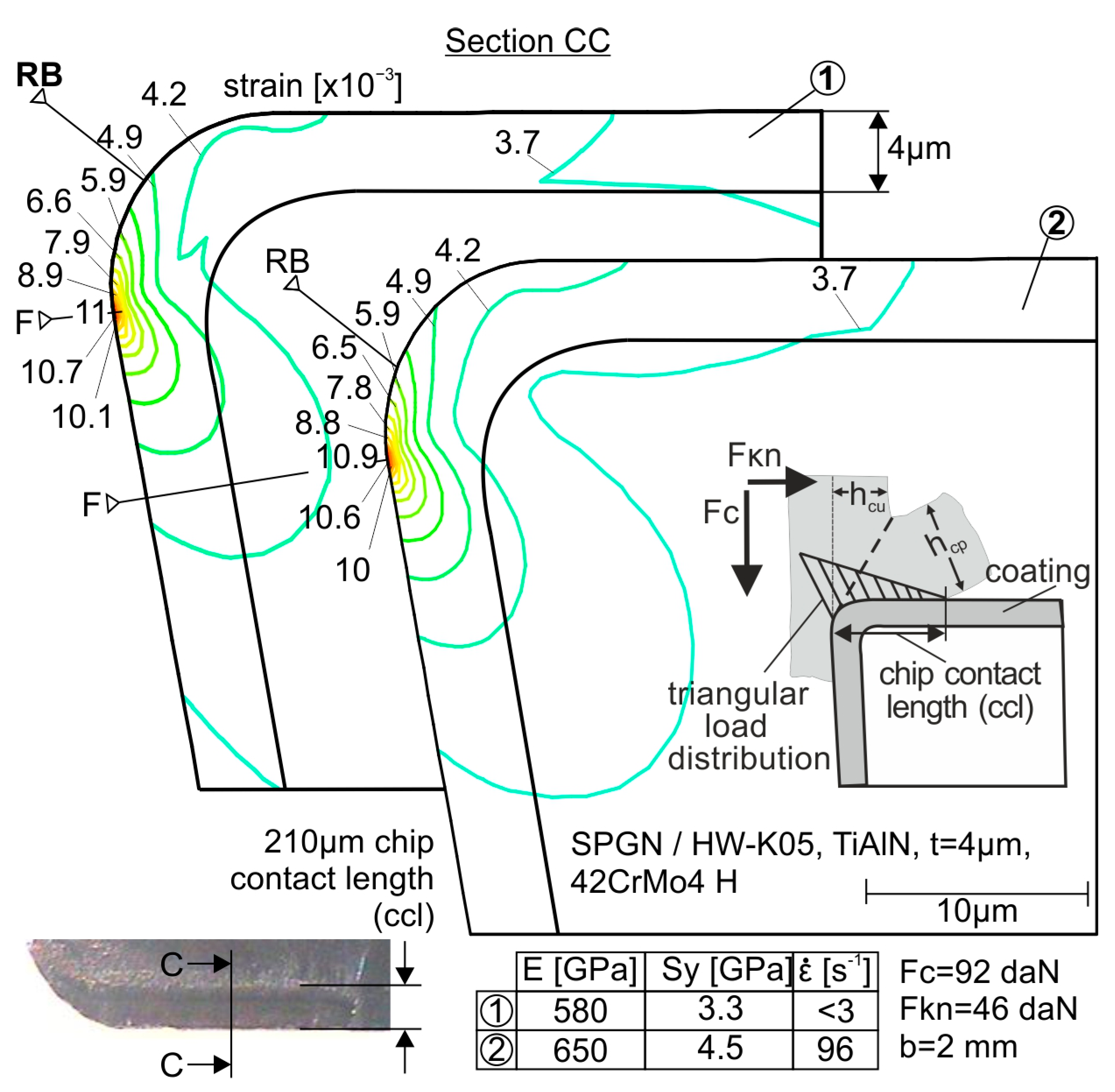
5.3. Explanation of the Wear Mechanisms on the Flank and Rake

The strain and strain-rate data demonstrated in Figure 9 are considered in the following to predict a potential start of the coating fatigue failure and evolution on the cutting edge flank and rake. The diagram of Figure 9 is illustrated in Figure 15 with linear scales in both axes for simplification reasons.
The points of the curve in Figure 15 refer to fatigue critical strain and strain-rate pairs of the applied coating. The Woehler-like diagrams associated with these critical strains versus the number of cutting edge entries NE into the workpiece material are presented in Figure 15. The four points marked with a star in the diagrams of Figure 14 and Figure 15 indicate the relevant fatigue critical strains to the applied strain rates (Figure 14), and to NE (Figure 15) in the conducted turning (T) and milling (I, II, III) investigations.
Considering Figure 15, no coating fatigue failure can develop in turning at both flank end (F) and rake begin (RB) regions defined in Figure 14, since the related strain and strain-rate combinations lie in the fatigue safe area of the relevant Woehler diagram. Hence, the prevailing tool wear mechanism on tool flank and rake in turning is abrasion, as already stated in Section 5.1. In contrast, in I and II milling cases, the strain and strain-rate combinations at F and RB are within the fatigue endangered area depicted in Figure 15. Moreover, considering the Woehler curves relevant to the cases I and II (see Figure 16), coating fatigue failures are expected to appear at the cutting edge flank after less than 102 cutting edge entries (NE) into the workpiece. Based on the same Woehler diagrams, considering the occurring strain and strain-rate data at RB in the cases I and II, coating fatigue failures start in the region of RB after around 1 × 10⁴ and 2.8 × 10⁴ NE, respectively. The achieved overall NEs up to VB0.15 amount to ca. 2.8 × 10⁴ and 4.8 × 10⁴ in cases I and II, respectively (see Figure 12). The coated tool in case I managed to cut 1.8 × 10⁴ times further up to VB0.15 after the coating fatigue failure start, while in case II it was 2 × 10⁴. This happens due to the smaller strain of 5.5 × 10⁻³ instead of 6 × 10⁻³ in cases II and I, respectively, and the slightly larger critical strain at the strain rate of 61 s−1 compared to 96 s−1 (see Figure 16). Hence, in cases I and II, the wear evolution was imposed through the interaction of the fatigue failures on F and RB with abrasion mechanisms. The tool-life increase in case III compared to cases I and II can be attributed mainly to the fact that in case III, no fatigue failure phenomena are activated on the rake. This happens, since in case III, the strain and strain-rate combination on RB (5 × 10⁻³/6.7 s−1) lies within the fatigue safe area shown in Figure 15. Thus, the related wear evolution on the rake is induced only by abrasion. In contrast, a coating fatigue failure starts on F after about 104 NEs and hence, the wear evolution on the flank is affected mainly by fatigue phenomena.
Lastly, it must be noted that the stabilization of the tool life at the level of 20 min at a strain of 5 × 10⁻³ and te longer than approximately 1 ms (i.e., strain rate of ca. 20 s−1), can be explained with the aid of Figure 15. The te of around 1 ms is associated with a fatigue critical strain of ca. 5 × 10⁻³, which increases along with the strain-rate reduction, as shown in Figure 15. Hence, te longer than 1 ms cannot trigger a coating fatigue failure on the tool rake since the strain on RB of 5 × 10⁻³ is always equal to or less than the critical one. In this way, at te longer than 1 ms, the wear evolution is like case III and the attainable tool life as that of this case as well. In this way, using such calculations, among others, the effect of the depth of cut to tool diameter ratio on the occurring tool strains can be predicted depended on the developed strain rates during the tool entry into the part and the expected tool life due to coating fatigue as well.

6. Conclusions

In this paper, the wear phenomena causing the wear evolution on the coated tool flank and rake in milling were explained.
  • These phenomena were investigated at various entry impact durations and compared with the related ones in turning, where quasistatic loads are acting on the cutting edge;
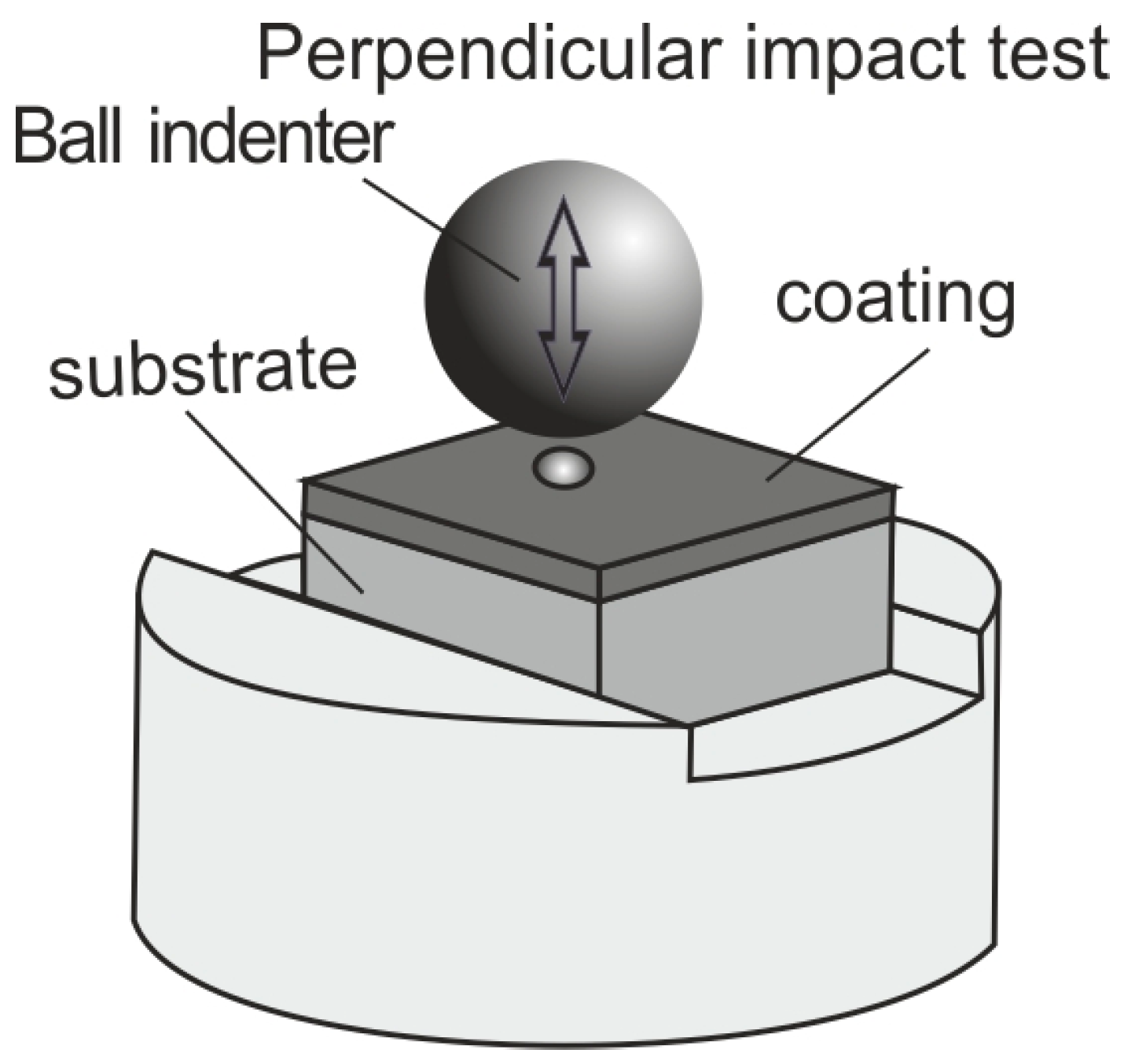
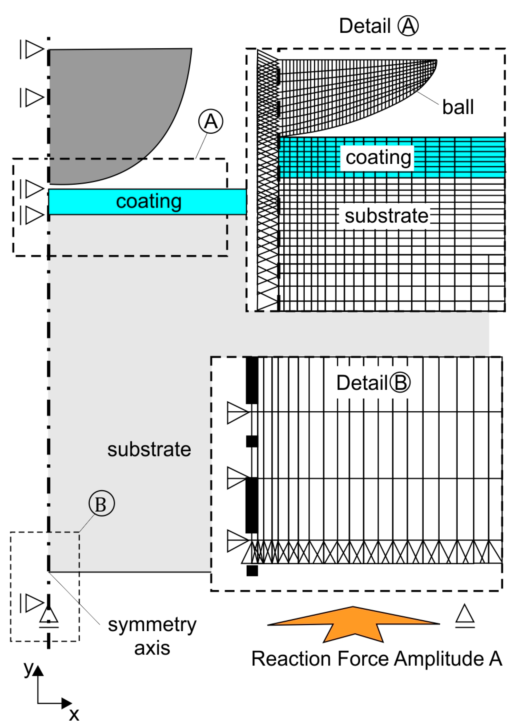
  • Hereto, the impact test technique was used to predict stress, strain, and strain-rate material properties of the applied cemented carbide substrate and its PVD TiAlN coating;
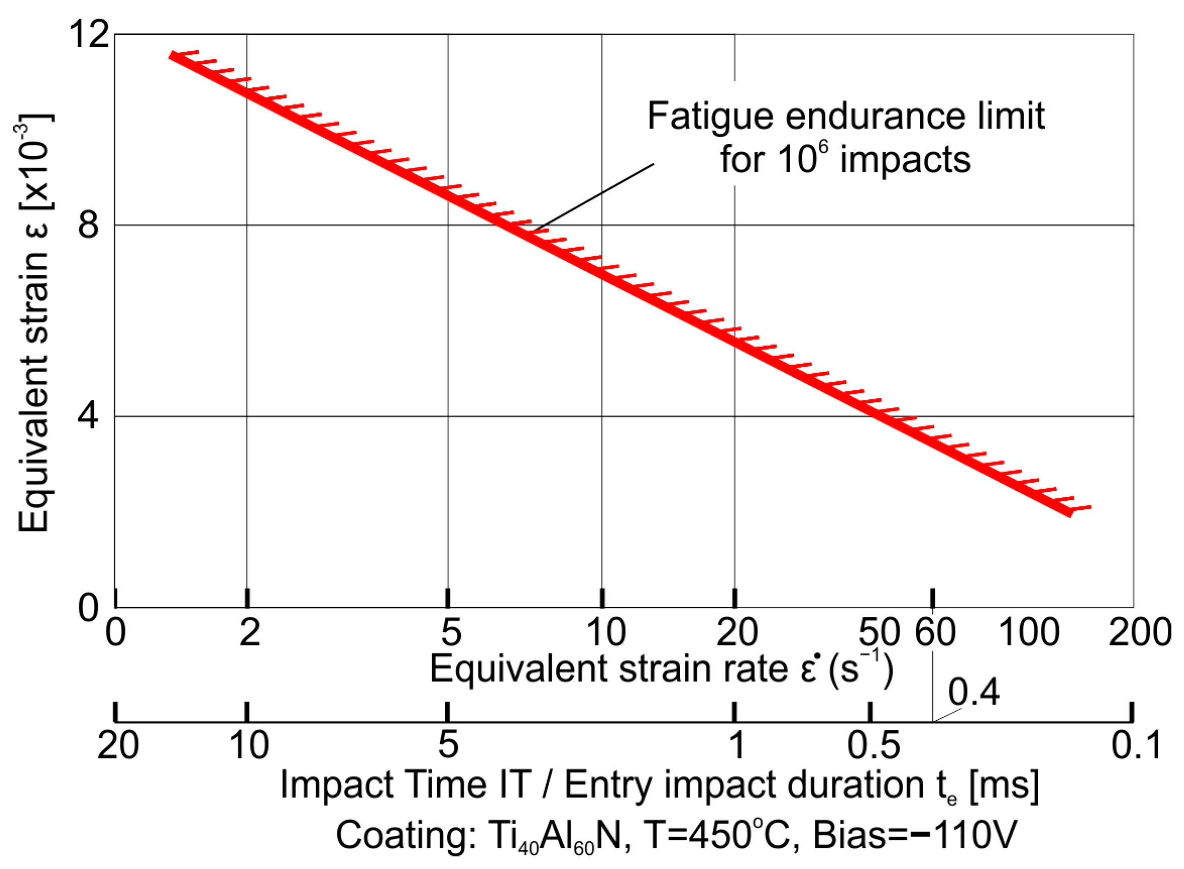
  • The obtained results show that at entry impact durations of less than 1 ms, the coating fatigue failure on the rake, and its interaction to that on the flank are the prevailing parameters affecting the tool life;
  • Considering this fact, the milling-tool geometry and the relevant cutting conditions can be appropriately selected to avoid entry impact durations significantly less than 1 ms;
  • In turning, as well as in milling, while increasing the entry impact duration, abrasion-mechanisms start playing the critical role for the wear development;
  • The presented experimental–analytical methods enable the prediction of the development of such wear mechanisms on coated tools. Furthermore, the latter innovative procedures can be also applied to check the effect of the cutting depth to tool diameter ratio as well as of the milling conditions on the tool life, thus, rendering their optimization possible.
Future works will be focused on clarifying the effect of various parameters like adhesion, structure, chemical composition, etc., on the coating dynamic material data, and thus, on assessing the coating fatigue endurance quality.

Author Contributions

Conceptualization, G.S. and K.-D.B.; methodology, G.S. and K.-D.B.; software, A.B.; validation, A.B. and D.T.; formal analysis, G.S. and A.B.; investigation, A.B., G.S., E.B., K.-D.B. and D.T.; resources, G.S. and A.B.; data curation, G.S. and A.B.; writing—original draft preparation, A.B., G.S., E.B. and K.-D.B.; writing—review and editing, A.B., G.S., E.B. and K.-D.B. All authors have read and agreed to the published version of the manuscript.

Funding

This research received no external funding.

Institutional Review Board Statement

Not applicable.

Informed Consent Statement

Not applicable.

Data Availability Statement

Data are contained within the article.

Conflicts of Interest

Author Antonios Bouzakis was employed by the company Impact-BZ. The remaining authors declare that the research was conducted in the absence of any commercial or financial relationships that could be construed as a potential conflict of interest.

References

  1. Bouzakis, K.-D.; Michailidis, N.; Skordaris, G.; Bouzakis, E.; Biermann, D.; M’Saoubi, R. Cutting with coated tools: Coating technologies, characterization methods and performance optimization. CIRP Ann. Manuf. Technol. 2012, 61, 703–723. [Google Scholar] [CrossRef]
  2. Hörling, A.; Hultman, L.; Odén, M.; Sjölén, J.; Karlsson, L. Mechanical Properties and Machining Performance of Ti1_xAlxN-Coated Cutting Tools. Surf. Coat. Technol. 2005, 191, 384–392. [Google Scholar] [CrossRef]
  3. Gong, F.; Zhao, J.; Jiang, Y.; Tao, H.; Li, Z.; Zang, J. Fatigue failure of coated carbide tool and its influence on cutting performance in face milling SkD11 hardened steel. Int. J. Refract. Met. Hard Mater. 2017, 64, 27–34. [Google Scholar] [CrossRef]
  4. Ruppi, S. Advances in Chemically Vapour Deposited Wear Resistant Coatings. J. Phys. IV France 2001, 1, Pr3-847–Pr3-859. [Google Scholar] [CrossRef]
  5. Bobzin, K.; Bagcivan, N.; Reinholdt, A.; Ewering, M. Thermal Stability of g-Al2O3 Coatings for Challenging Cutting Operations. Surf. Coat. Technol. 2010, 205, 1444–1448. [Google Scholar] [CrossRef]
  6. Sousa, V.F.C.; Silva, F.J.G.; Alexandre, R.; Fecheira, J.S.; Silva, F.P.N. Study of the wear behavior of TiAlSiN and TiAlN PVD coated tools on milling operations of pre-hardened tool steel. Wear 2021, 476, 203695. [Google Scholar] [CrossRef]
  7. Ren, Z.; Qu, S.; Zhang, Y.; Li, X.; Yang, C. Machining Performance of TiAlN-Coated Cemented Carbide Tools with Chip Groove in Machining Titanium Alloy Ti-6Al-0.6Cr-0.4Fe-0.4Si-0.01B. Metals 2018, 8, 850. [Google Scholar] [CrossRef]
  8. Wang, B.; Li, A.; Liu, G. Cutting performance and wear mechanisms of TiAlN PVD-coated cemented carbide tool in high-speed turning of Ti-5Al-2Sn-2Zr-4Mo-4Cr alloy. J. Mech. Sci. Technol. 2020, 7, 34. [Google Scholar] [CrossRef]
  9. Tiwari, P.K.; Raj, S.; Kumar, R.; Panda, A.; Sahoo, A.K. Machinability improvement investigation in face milling of Ti–3Al–2.5V alloys using TiAlN coated carbide insert under dual nozzle minimum quantity lubrication cooling environment. Proc. Inst. Mech. Eng. Part E J. Process Mech. Eng. 2022. [Google Scholar] [CrossRef]
  10. Bayraktar, S.; Hekimoglu, A.P.; Turgut, Y.; Haciosmanoglu, M. A Performance Comparison Study of Uncoated and TiAlN Coated Carbide End Mill on Machining of the Al-35Zn Alloy. Mater. Sci. Eng. 2018, 295, 012013. [Google Scholar] [CrossRef]
  11. Edelbi, A.; Kumar, R.; Sahoo, A.K.; Pandey, A. Comparative Machining Performance Investigation of Dual-Nozzle MQL-Assisted ZnO and Al2O3 Nanofluids in Face Milling of Ti–3Al. Arab. J. Sci. Eng. 2023, 48, 2969–2993. [Google Scholar] [CrossRef]
  12. Hovsepian, P.E.; Ehiasarian, A.P.; Ratayski, U. CrAlYCN/CrCN Nanoscale Multilayer PVD Coatings Deposited by the Combined High Power Impulse Magnetron Sputtering/Unbalanced Magnetron Sputtering (HIPIMS/UBM) Technology. Surf. Coat. Technol. 2009, 203, 1237–1243. [Google Scholar] [CrossRef]
  13. Bobzin, K.; Bagcivan, N.; Immich, P.; Bolz, S.; Alami, J.; Cremer, R. Advantages of Nanocomposite Coatings Deposited by High Power Pulse Magnetron Sputtering Technology. J. Mater. Process. Technol. 2009, 209, 165–170. [Google Scholar] [CrossRef]
  14. Ishii, T.; Shima, N.; Ueda, H.; Okayama, S.; Gonda, M. Microstructural Investigation of a-Al2O3-Epitaxially Coated Cemented Carbide Cutting Tools. J. Vac. Sci. Technol. A 2001, 19, 633–639. [Google Scholar] [CrossRef]
  15. Alami, J.; Persson, P.O.A.; Music, D.; Gudmundsson, J.T.; Bohlmark, J.; Helmersson, U. On-assisted Physical Vapor Deposition for Enhanced Film Properties on Nonflat Surfaces. J. Vac. Sci. Technol. A 2005, 23, 278–280. [Google Scholar] [CrossRef]
  16. Michailidis, N. Variations in the cutting performance of PVD-coated tools in milling Ti6Al4V, explained through temperature-dependent coating properties. Surf. Coat. Technol. 2016, 304, 325–329. [Google Scholar] [CrossRef]
  17. Bouzakis, K.-D.; Makrimalakis, S.; Skordaris, G.; Kombogiannis, S.; Katirtzoglou, G.; Maliaris, G. Coated tools’ performance in up and down milling stainless steel, explained by film mechanical and fatigue properties. Wear 2013, 303, 546–559. [Google Scholar] [CrossRef]
  18. Meyers, M.A. Dynamic Behavior of Materials; John Wiley and Sons: New York, NY, USA, 1994. [Google Scholar]
  19. Murr, L.E. Metallurgical effects of shock and high-strain-rate loading. In Materials at High Strain Rates; Blazynski, T.Z., Ed.; Elsevier: Essex, UK, 1987; pp. 1–46. [Google Scholar]
  20. Harding, J. The effect of high strain rates on material properties. In Materials at High Strain Rates; Blazynski, T.Z., Ed.; Elsevier: Essex, UK, 1987; pp. 133–186. [Google Scholar]
  21. Bouzakis, K.-D.; Maliaris, G.; Makrimalakis, S. Strain rate effect on the fatigue failure of thin PVD coatings: An investigation by a novel impact tester with adjustable repetitive force. Int. J. Fatigue 2012, 44, 89–97. [Google Scholar] [CrossRef]
  22. Knotek, O.; Bosserhoff, B.; Schrey, A.; Leyendecker, T.; Lemmer, O.; Esser, S. A new technique for testing the impact load of thin films: The coating impact test. Surf. Coat. Technol. 1992, 54–55, 102–107. [Google Scholar] [CrossRef]
  23. Knotek, O.; Lugscheider, E.; Löffler, F.; Schrey, A.; Bosserhoff, B. Behaviour of CVD and PVD coatings under impact load. Surf. Coat. Technol. 1994, 68–69, 253–258. [Google Scholar] [CrossRef]
  24. Bobzin, K.; Kalscheuer, C.; Tayyab, M. Effect of CrAIN coating properties on impact fatigue of tool steel. Surf. Coat. Technol. 2023, 471, 129869. [Google Scholar] [CrossRef]
  25. Impact-BZ Ltd. Available online: www.impact-bz.com (accessed on 21 November 2023).
  26. Teppernegg, T.; Klunsner, T.; Kremsner, C.; Tritremmel, C.; Czettl, C.; Puchegger, S.; Ebner, R. High temperature mechanical properties of WC-Co hard metals. Int. J. Refract. Met. Hard Mater. 2016, 56, 139–144. [Google Scholar] [CrossRef]
  27. Bouzakis, A.; Skordaris, G.; Bouzakis, K.-D.; Gökcen, M.-G.; Boumpakis, A.; Batuk, A.U.; Sisman, S. Stress, strain and strain rate cemented carbide properties determined with a fem-supported evaluation of impact test imprints. Int. J. Refract. Met. Hard Mater. 2021, 94, 105384. [Google Scholar] [CrossRef]
Figure 1. Repetitive impacts on a coated specimen by a ball indenter.
Coatings 13 01982 g001
Figure 2. Impact test devices to obtain various impact times.
Coatings 13 01982 g002
Figure 3. (a) Time course of the applied impact force; (b) creation of a Woehler-like diagram for a PVD TiAlN coating on cemented carbide substrate K05, associated with an impact time IT of 0.45 ms conducted in an ambient temperature.
Coatings 13 01982 g003
Figure 4. The applied FEM model to determine stress, strain, and strain-rate fields in the coating and its substrate during the impact test.
Coatings 13 01982 g004
Figure 5. (a) Nanoindentation results on the applied K05 substrate and TiAlN coating; (b) calculated stress–strain curves of the employed coating and its substrate.
Coatings 13 01982 g005
Figure 6. Constitutive laws of a cemented carbide at various strain rates.
Coatings 13 01982 g006
Figure 7. Stress and strain fields developed in the TiAlN coating and its K05 substrate at a constant load, and various impact times.
Coatings 13 01982 g007
Figure 8. Coating fatigue endurance or failure after 106 impacts investigated at ambient temperature by the impact test at various impact forces and impact times.
Coatings 13 01982 g008
Figure 9. Equivalent strain over the equivalent strain rate for coating fatigue endurance up to 106 impacts.
Coatings 13 01982 g009
Figure 10. (a) The applied cutting conditions in milling and turning investigations; (b) recording the rake wear status by confocal microscopy.
Coatings 13 01982 g010
Figure 11. Temperature distributions within the coated tool versus the cutting speed at three distinct positions of the cutting wedge.
Coatings 13 01982 g011
Figure 12. Wear evolution on the flank in the investigated milling cases and turning.
Coatings 13 01982 g012
Figure 13. Wear status on the rake in the previous cases.
Coatings 13 01982 g013
Figure 14. FEM determined strains in the cutting edge for various substrate data.
Coatings 13 01982 g014
Figure 15. Strain and strain-rate combinations on significant points of the cutting edge and their position in the diagram demonstrating the coating fatigue safe strain and strain-rate areas.
Coatings 13 01982 g015
Figure 16. Prediction of the coating fatigue failure start on the previous significant points in the investigated cases considering Woehler-like diagrams.
Coatings 13 01982 g016
Disclaimer/Publisher’s Note: The statements, opinions and data contained in all publications are solely those of the individual author(s) and contributor(s) and not of MDPI and/or the editor(s). MDPI and/or the editor(s) disclaim responsibility for any injury to people or property resulting from any ideas, methods, instructions or products referred to in the content.

