
Simulation of 1500 °C Thermal Shock for Novel Structural Thermal/Environmental Barrier Coatings System

Abstract
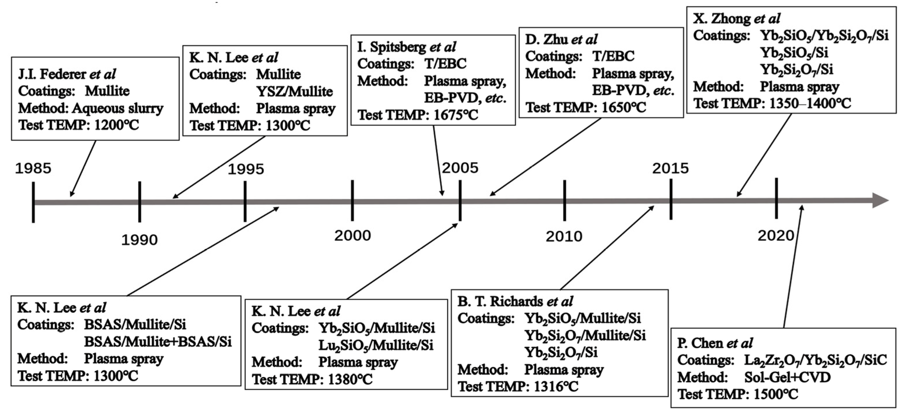
:1. Introduction
2. Experiments and Numerical Models
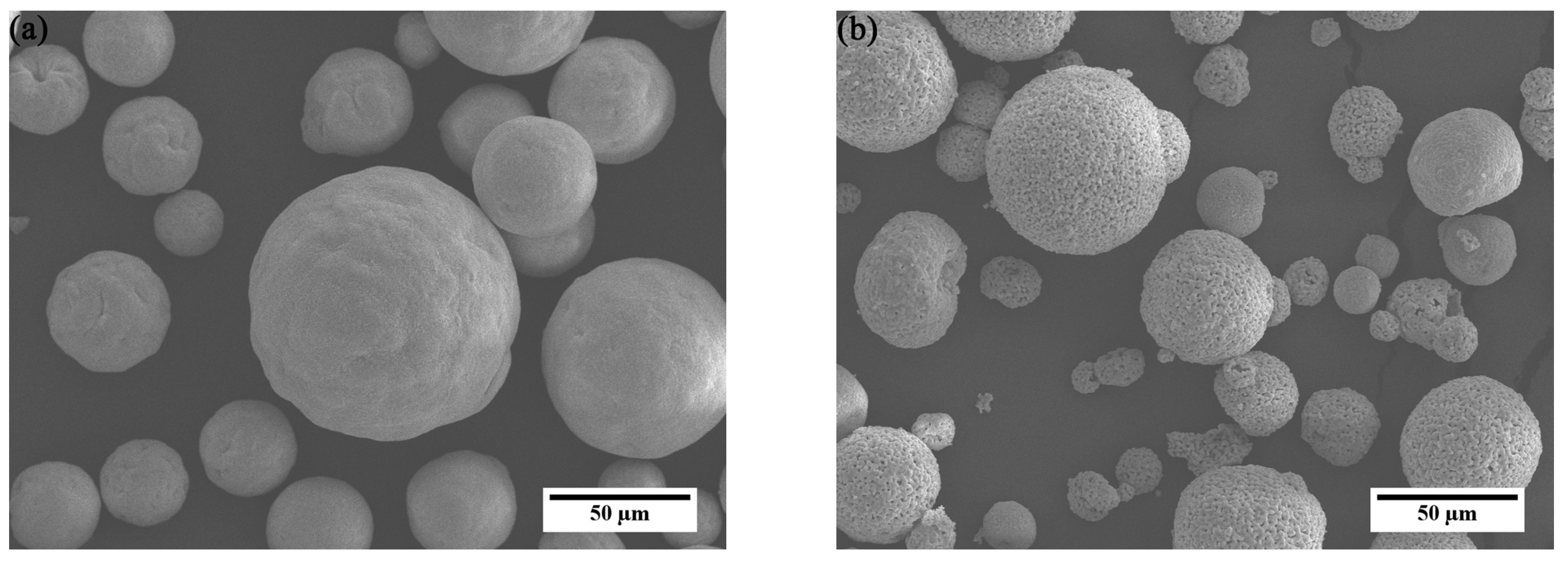
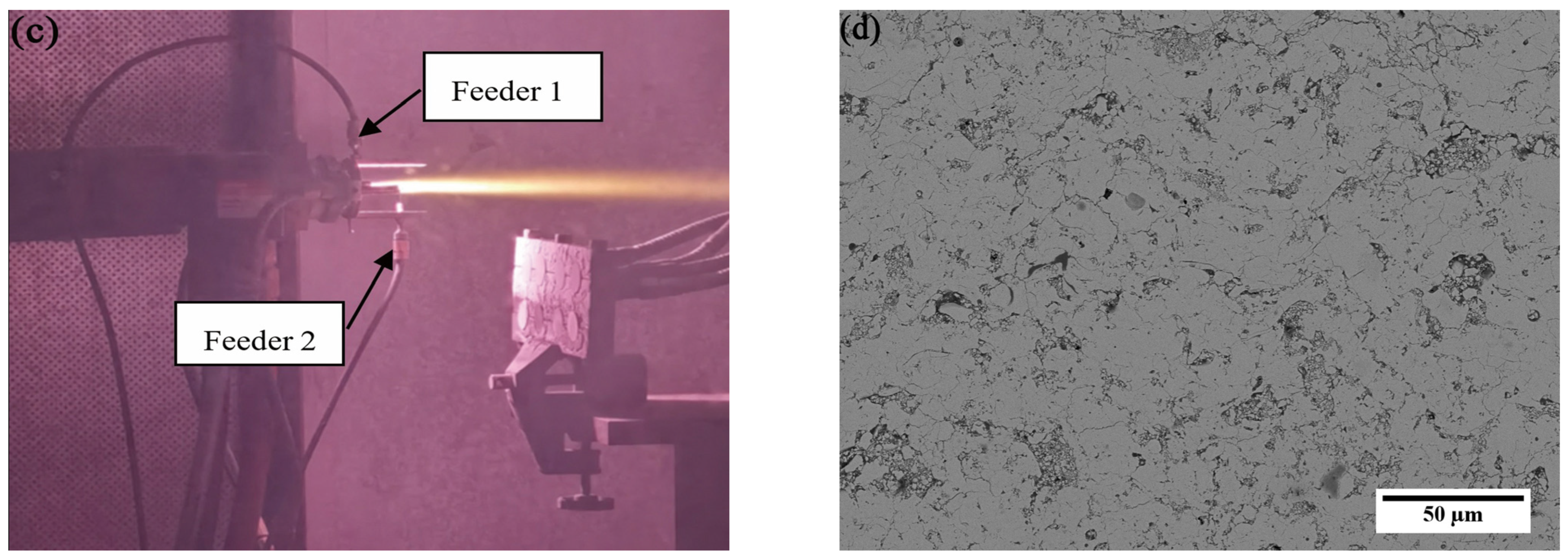
2.1. Coating Preparation
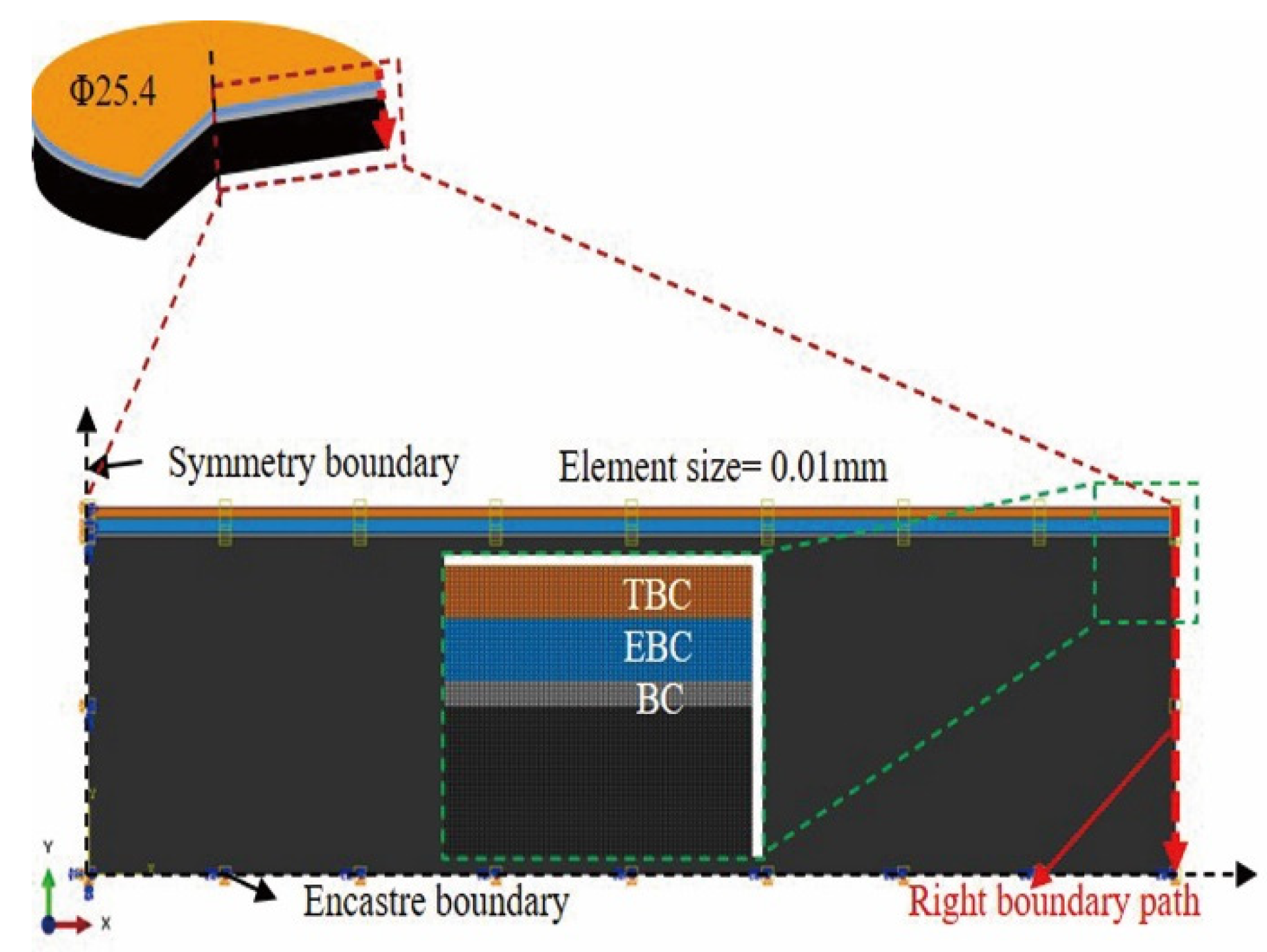
2.2. FE Model and Boundary Conditions
3. Material Parameters
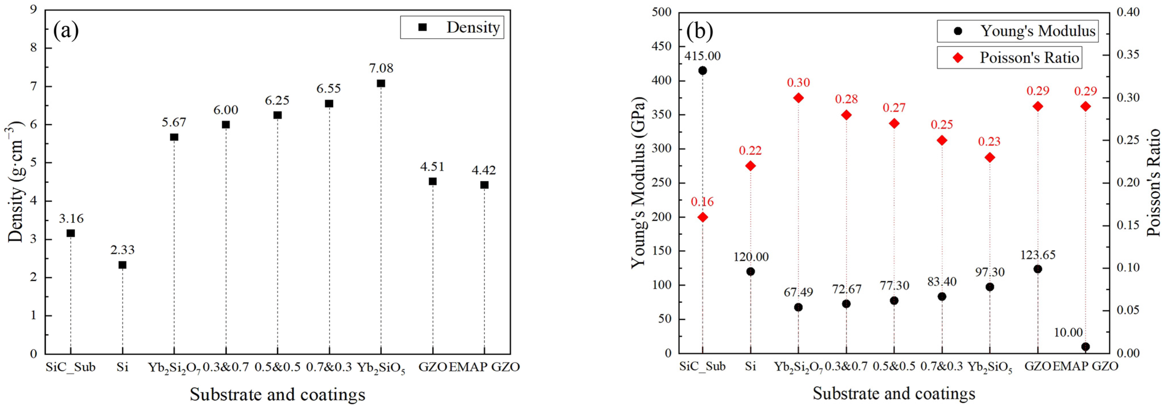
3.1. Density, Young’s Modulus, and Poisson’s Ratio
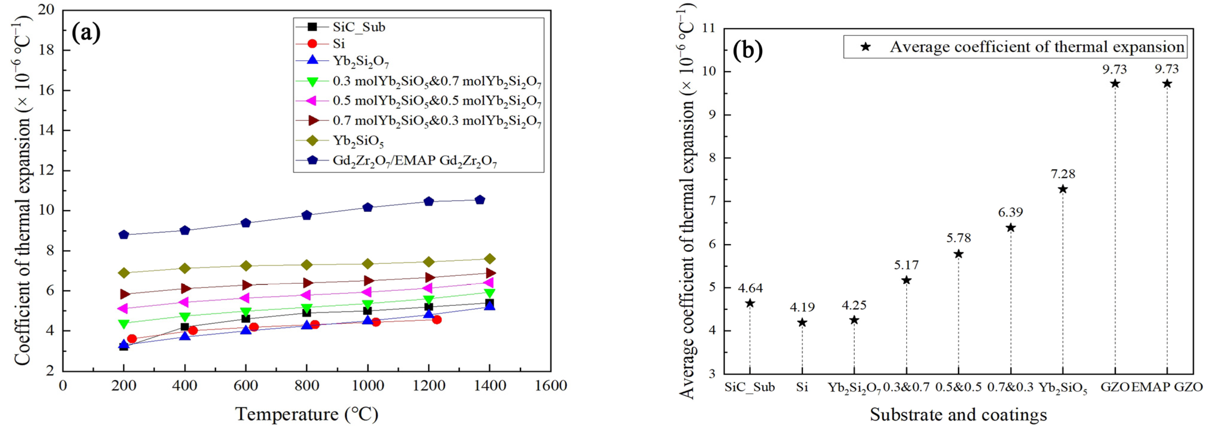
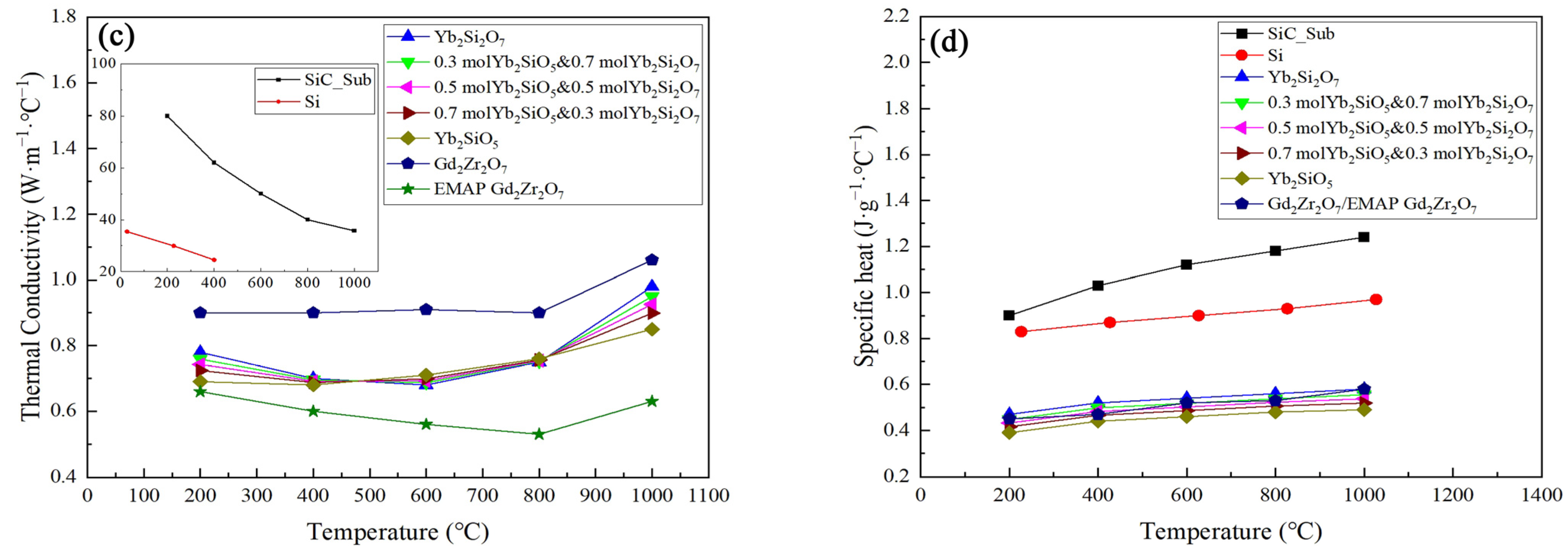
3.2. Thermal Parameters
3.3. Thermal Parameters Measurement
4. Results and Discussion
4.1. Comparison of EMAP T/EBCs with T/EBCs
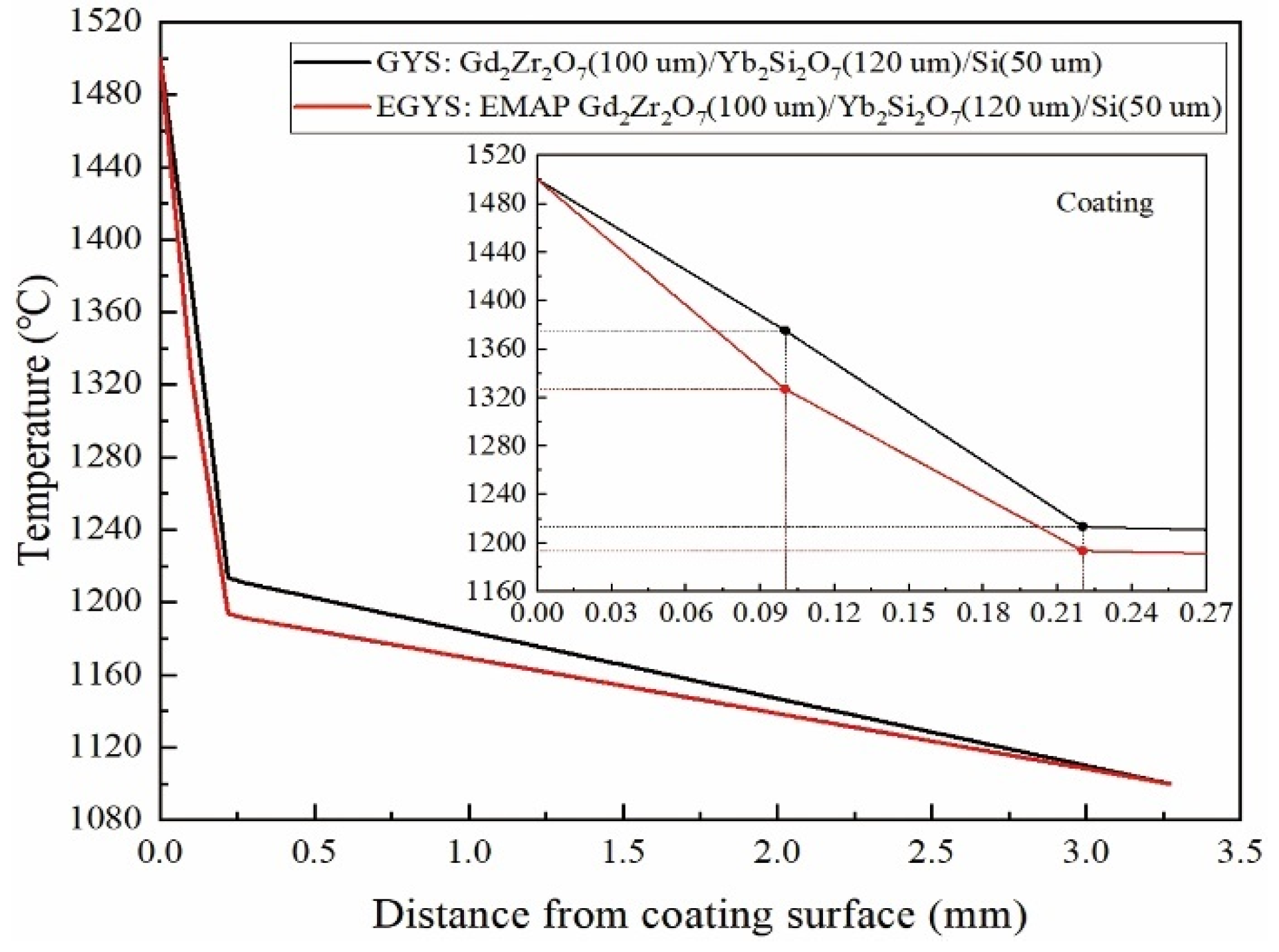
4.1.1. Temperature Distributions
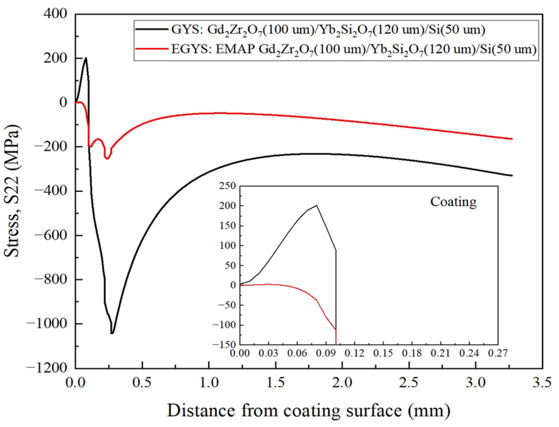
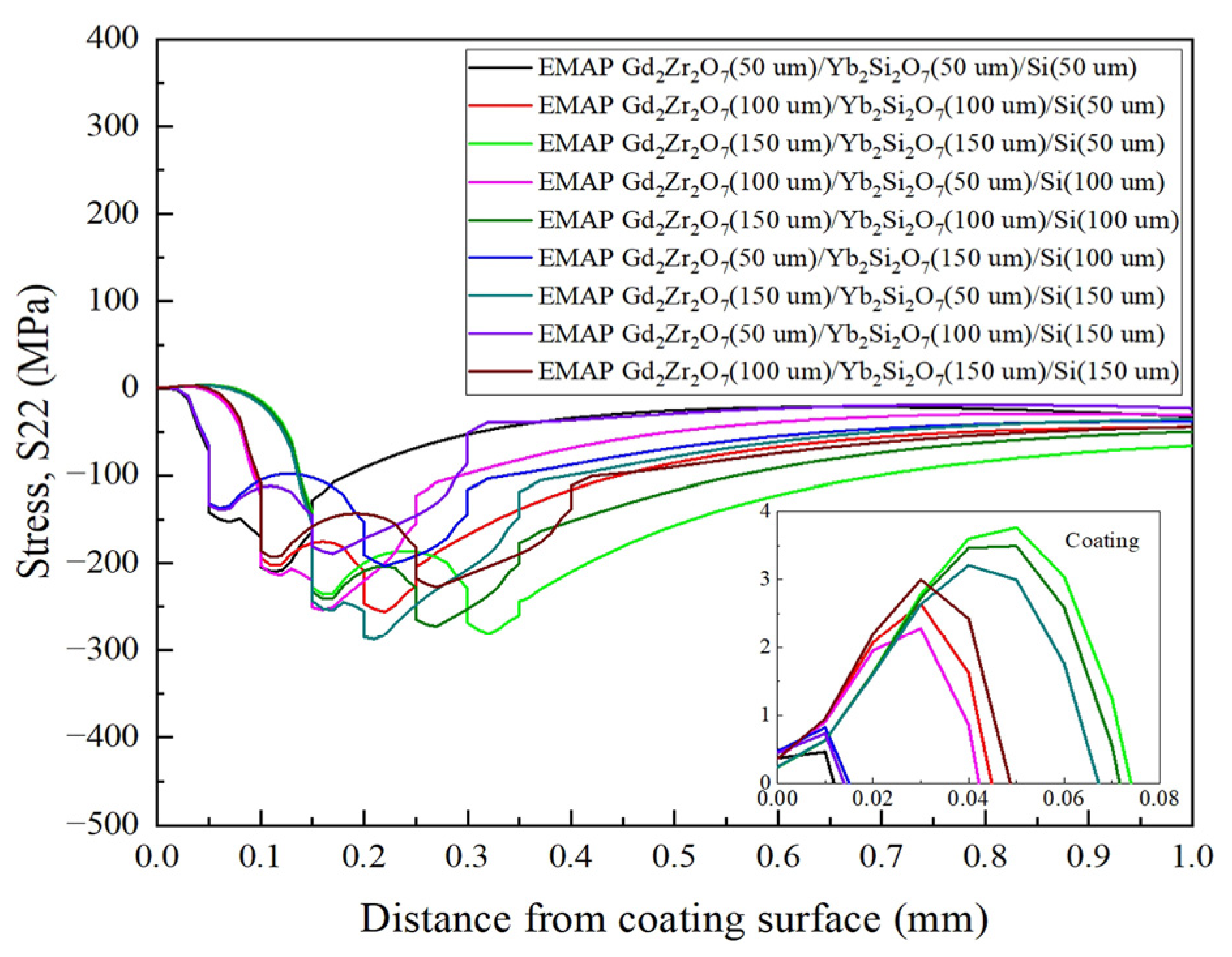
4.1.2. Stress Distributions
4.2. EMAP T/EBCs Thickness Design
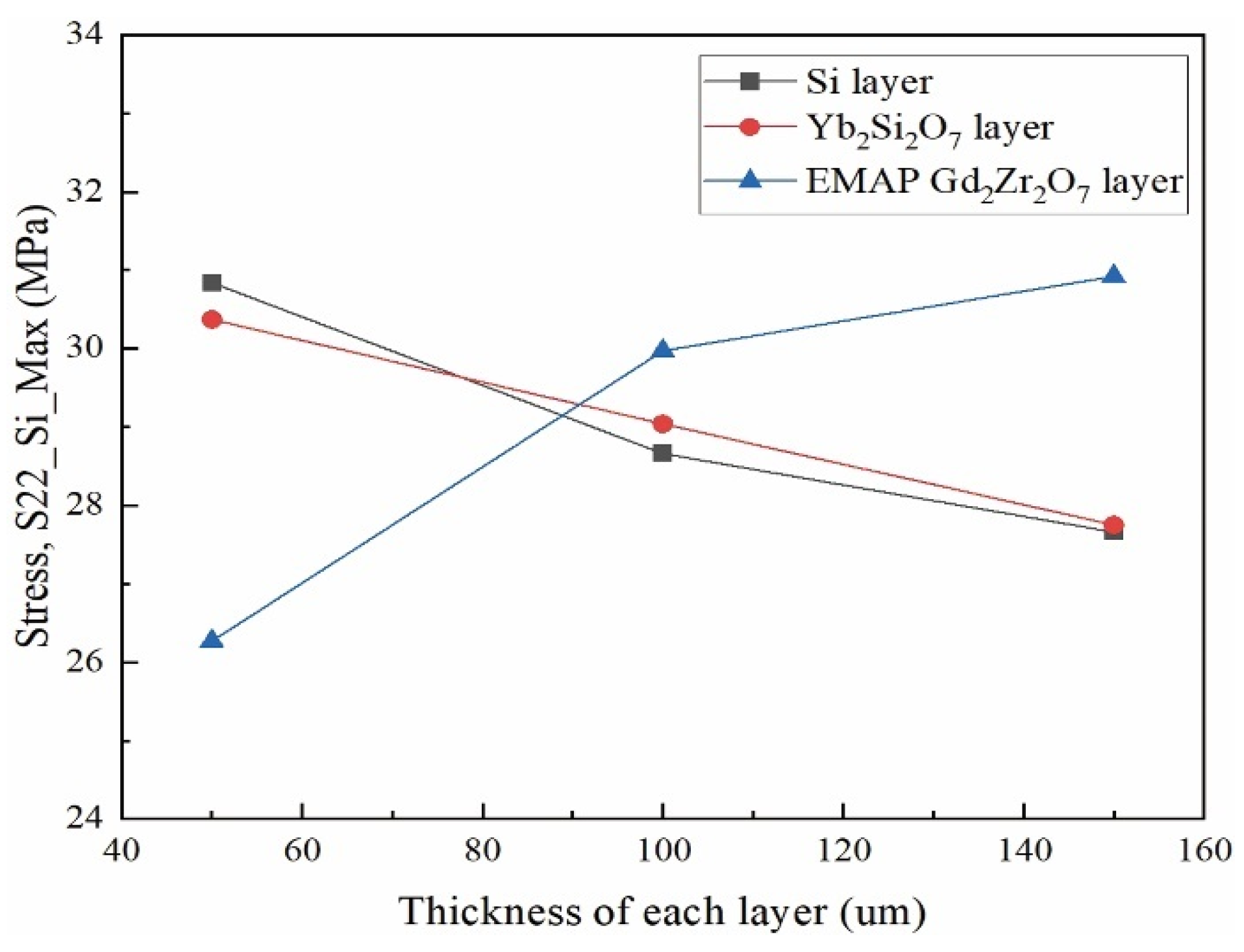
4.2.1. Single Variable Method
4.2.2. Orthogonal Experiment Method
4.3. Effect of Yb2SiO5 Doping
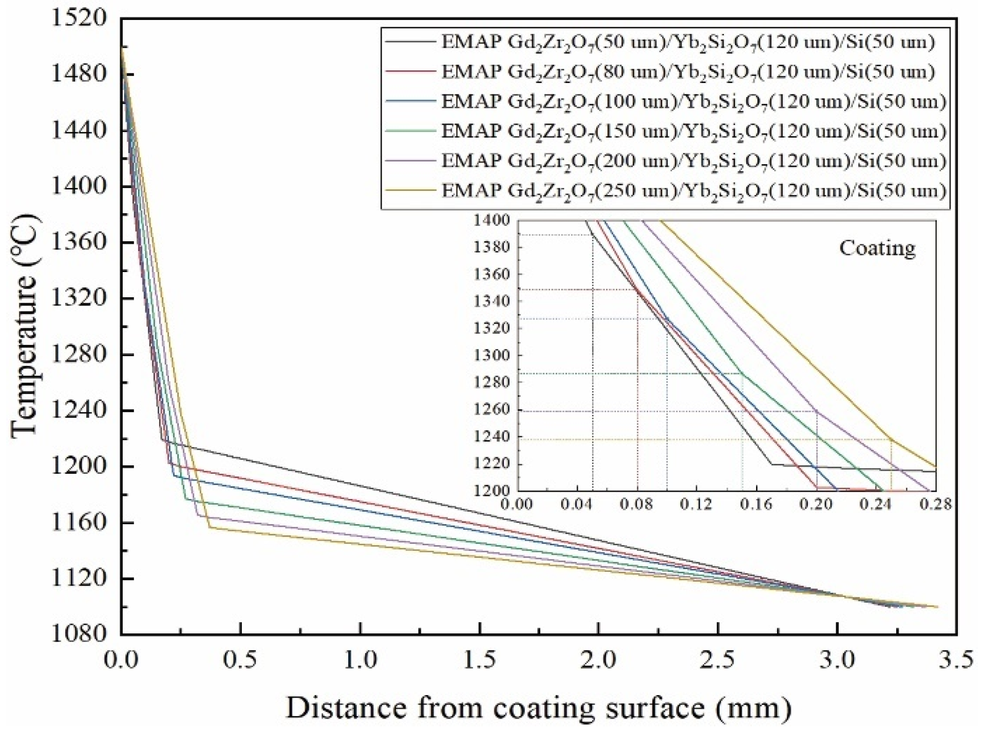
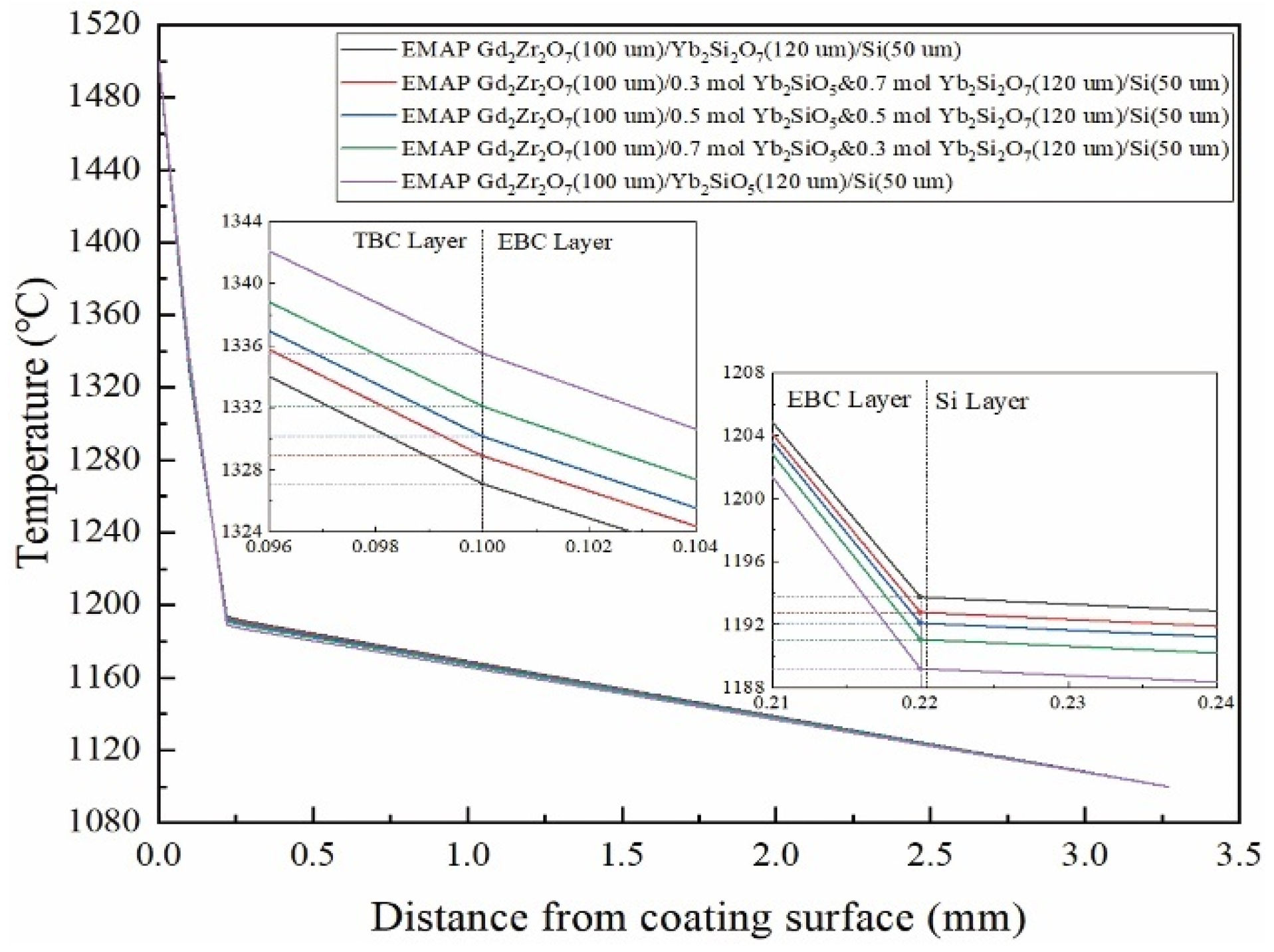
4.3.1. Response of the Temperature Field
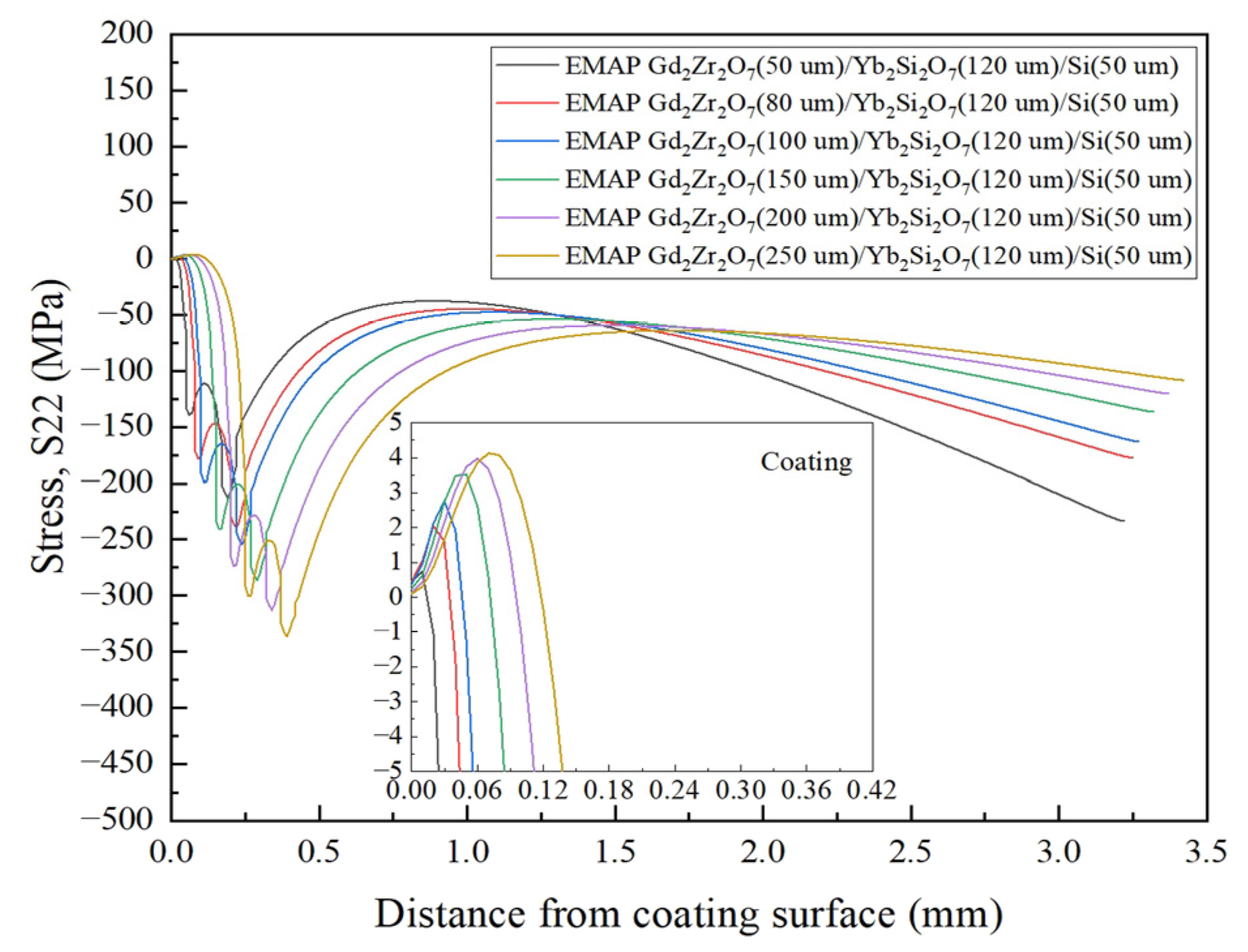
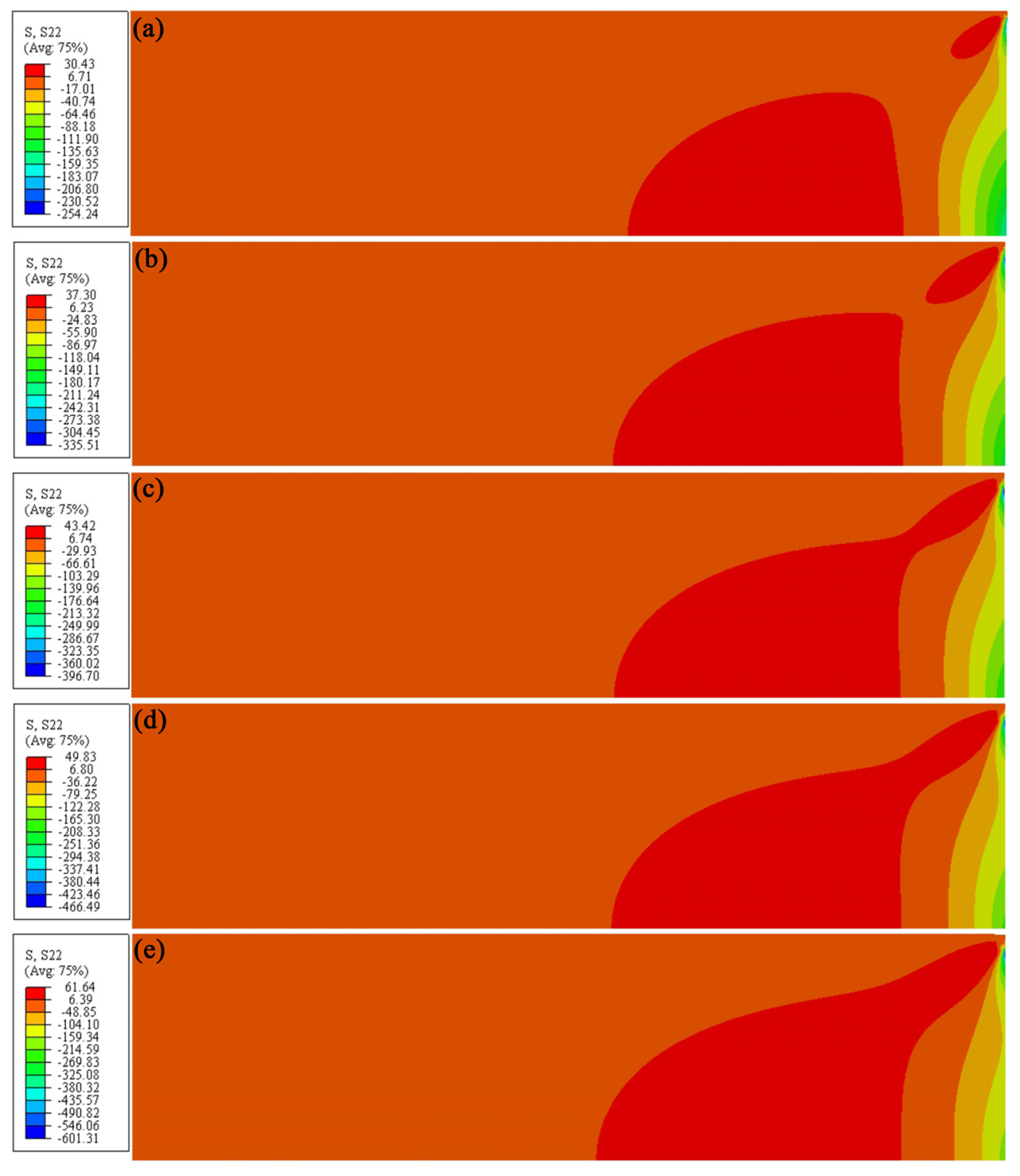
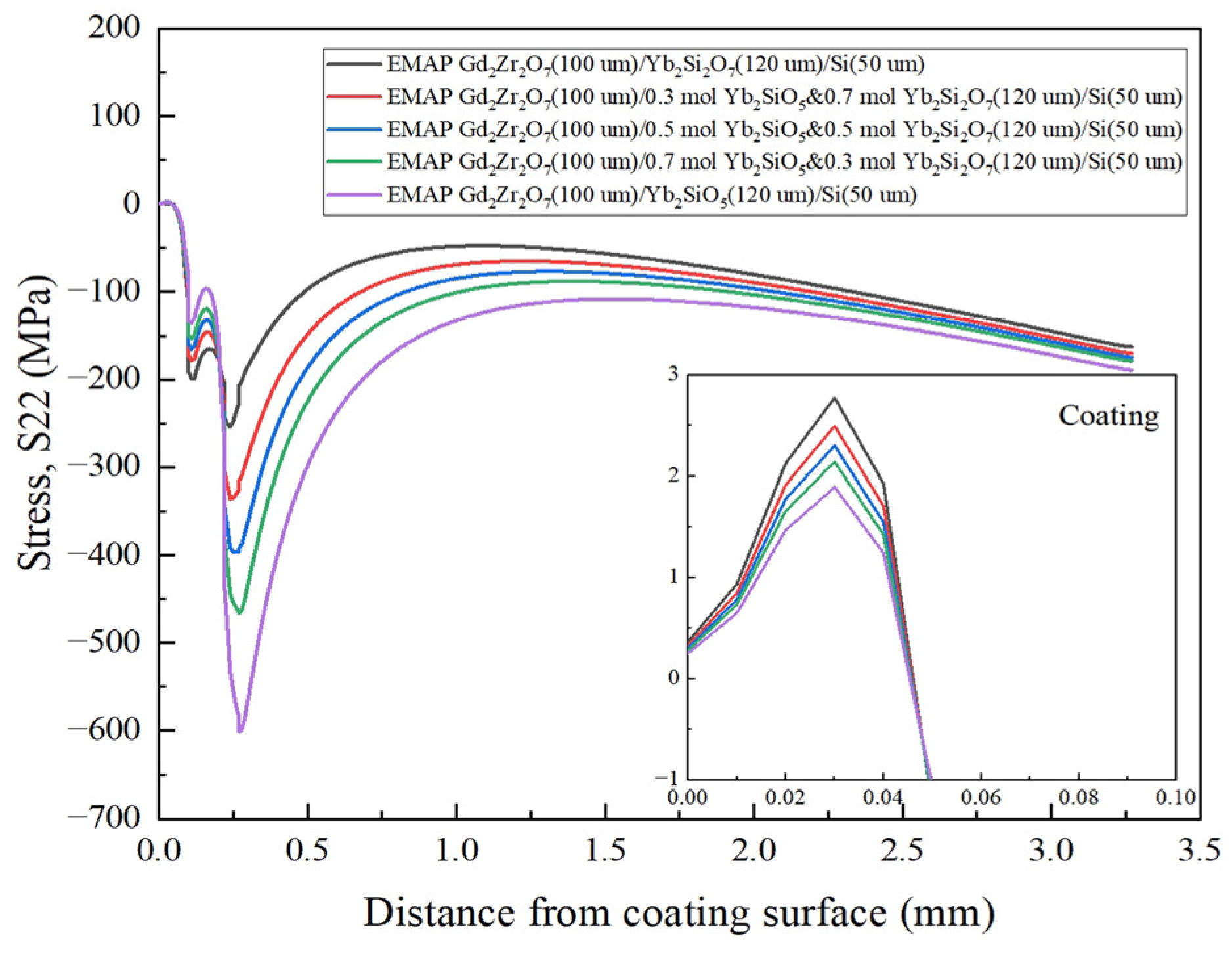
4.3.2. Response of Stress Field
5. Conclusions
Author Contributions
Funding
Institutional Review Board Statement
Informed Consent Statement
Data Availability Statement
Acknowledgments
Conflicts of Interest
Appendix A

| Material | Temperature (°C) | Thermal Expansion Coefficient (×10−6·°C−1) | Thermal Conductivity (W·m−1·°C−1) | Specific Heat (J·g−1·°C−1) | Elastic Modulus (Gpa) | Poisson’s Ratio | Density (g·cm−3) |
|---|---|---|---|---|---|---|---|
| α-SiC | 20 | - | - | - | 415.00 | 0.16 | 3.16 |
| 200 | 3.20 | 80.00 | 0.90 | - | - | - | |
| 400 | 4.20 | 62.00 | 1.03 | - | - | - | |
| 600 | 4.60 | 50.00 | 1.12 | - | - | - | |
| 800 | 4.90 | 40.00 | 1.18 | - | - | - | |
| 1000 | 5.00 | 35.70 | 1.24 | - | - | - | |
| 1200 | 5.20 | - | - | - | - | - | |
| 1400 | 5.40 | - | - | - | - | - | |
| Si | 27 | - | 35.40 | - | 120 | 0.22 | 2.33 |
| 227 | 3.61 | 29.90 | 0.83 | - | - | - | |
| 400 | - | 24.50 | - | - | - | - | |
| 427 | 4.02 | - | 0.87 | - | - | - | |
| 627 | 4.19 | - | 0.90 | - | - | - | |
| 827 | 4.32 | - | 0.93 | - | - | - | |
| 1027 | 4.44 | - | 0.97 | - | - | - | |
| 1227 | 4.56 | - | - | - | - | - | |
| Yb2SiO5 | 25 | - | - | - | 97.30 | 0.23 | 7.08 |
| 200 | 6.90 | 0.69 | 0.39 | - | - | - | |
| 400 | 7.13 | 0.68 | 0.44 | - | - | - | |
| 600 | 7.25 | 0.71 | 0.46 | - | - | - | |
| 800 | 7.30 | 0.76 | 0.48 | - | - | - | |
| 1000 | 7.35 | 0.85 | 0.49 | - | - | - | |
| 1200 | 7.45 | - | - | - | - | - | |
| 1400 | 7.60 | - | - | - | - | - | |
| Yb2Si2O7 | 25 | - | - | - | 67.49 | 0.30 | 5.67 |
| 200 | 3.30 | 0.78 | 0.47 | - | - | - | |
| 400 | 3.70 | 0.70 | 0.52 | - | - | - | |
| 600 | 4.00 | 0.68 | 0.54 | - | - | - | |
| 800 | 4.25 | 0.75 | 0.56 | - | - | - | |
| 1000 | 4.50 | 0.98 | 0.58 | - | - | - | |
| 1200 | 4.80 | - | - | - | - | - | |
| 1400 | 5.20 | - | - | - | - | - |
| Material | Temperature (°C) | Thermal Expansion Coefficient (×10−6·°C−1) | Thermal Conductivity (W·m−1·°C−1) | Specific Heat (J·g−1·°C−1) | Elastic Modulus (Gpa) | Poisson’s Ratio | Density (g·cm−3) |
|---|---|---|---|---|---|---|---|
| 0.3 mol Yb2SiO5 & 0.7 mol Yb2Si2O7 | 25 | - | - | - | 72.67 | 0.28 | 6.00 |
| 200 | 4.39 | 0.76 | 0.45 | - | - | - | |
| 400 | 4.74 | 0.70 | 0.50 | - | - | - | |
| 600 | 4.99 | 0.69 | 0.52 | - | - | - | |
| 800 | 5.18 | 0.75 | 0.54 | - | - | - | |
| 1000 | 5.37 | 0.95 | 0.56 | - | - | - | |
| 1200 | 5.61 | - | - | - | - | - | |
| 1400 | 5.93 | - | - | - | - | - | |
| 0.5 mol Yb2SiO5 & 0.5 mol Yb2Si2O7 | 25 | - | - | - | 77.30 | 0.27 | 6.25 |
| 200 | 5.12 | 0.74 | 0.43 | - | - | - | |
| 400 | 5.43 | 0.69 | 0.48 | - | - | - | |
| 600 | 5.64 | 0.69 | 0.50 | - | - | - | |
| 800 | 5.79 | 0.75 | 0.52 | - | - | - | |
| 1000 | 5.94 | 0.93 | 0.54 | - | - | - | |
| 1200 | 6.14 | - | - | - | - | - | |
| 1400 | 6.41 | - | - | - | - | - | |
| 0.7 mol Yb2SiO5 & 0.3 mol Yb2Si2O7 | 25 | - | - | - | 83.40 | 0.25 | 6.55 |
| 200 | 5.83 | 0.72 | 0.42 | - | - | - | |
| 400 | 6.12 | 0.69 | 0.47 | - | - | - | |
| 600 | 6.29 | 0.70 | 0.49 | - | - | - | |
| 800 | 6.40 | 0.76 | 0.51 | - | - | - | |
| 1000 | 6.51 | 0.90 | 0.52 | - | - | - | |
| 1200 | 6.67 | - | - | - | - | - | |
| 1400 | 6.89 | - | - | - | - | - |
| Material | Temperature (°C) | Thermal Expansion Coefficient (×10−6·°C−1) | Thermal Conductivity (W·m−1·°C−1) | Specific Heat (J·g−1·°C−1) | Elastic Modulus (Gpa) | Poisson’s Ratio | Density (g·cm−3) |
|---|---|---|---|---|---|---|---|
| Gd2Zr2O7 | 25 | - | - | - | 123.65 | 0.29 | 4.51 |
| 200 | 8.80 | 0.90 | 0.45 | - | - | - | |
| 400 | 9.02 | 0.90 | 0.47 | - | - | - | |
| 600 | 9.39 | 0.91 | 0.52 | - | - | - | |
| 800 | 9.77 | 0.90 | 0.53 | - | - | - | |
| 1000 | 10.15 | 1.06 | 0.58 | - | - | - | |
| 1200 | 10.45 | - | - | - | - | - | |
| 1368 | 10.53 | - | - | - | - | - | |
| EMAP Gd2Zr2O7 | 25 | - | - | - | 10 | 0.29 | 4.42 |
| 200 | 8.80 | 0.66 | 0.45 | - | - | - | |
| 400 | 9.02 | 0.60 | 0.47 | - | - | - | |
| 600 | 9.39 | 0.56 | 0.52 | - | - | - | |
| 800 | 9.77 | 0.53 | 0.53 | - | - | - | |
| 1000 | 10.15 | 0.63 | 0.58 | - | - | - | |
| 1200 | 10.45 | - | - | - | - | - | |
| 1368 | 10.53 | - | - | - | - | - |
References
- Opila, E.J.; Fox, D.S.; Jacobson, N.S. Mass spectrometric identification of Si–O–H(g) species from the reaction of silica with water vapor at atmospheric pressure. J. Am. Ceram. Soc. 1997, 80, 1009–1012. [Google Scholar] [CrossRef]
- Opila, E.J.; Smialek, J.L.; Robinson, R.C.; Fox, D.S.; Jacobson, N.S. SiC recession due to SiO2 scale volatility under combustion conditions: II, thermodynamics and gaseous diffusion model. J. Am. Ceram. Soc. 1999, 82, 1826–1834. [Google Scholar] [CrossRef]
- Opila, E.J. Variation of the oxidation rate of silicon carbide with water-vapor pressure. J. Am. Ceram. Soc. 1999, 82, 625–636. [Google Scholar] [CrossRef]
- Opila, E.J. Oxidation and volatilization of silica formers in water vapor. J. Am. Ceram. Soc. 2003, 86, 1238–1248. [Google Scholar] [CrossRef] [Green Version]
- Federer, J.I. Alumina base coatings for protection of SiC ceramics. J. Mater. Eng. 1990, 12, 141–149. [Google Scholar] [CrossRef]
- Lee, K.N.; Jacobson, N.S.; Miller, R.A. Refractory oxide coatings on SiC ceramics. MRS Bull. 1994, 19, 35–38. [Google Scholar] [CrossRef] [Green Version]
- Lee, K.N.; Miller, R.A. Development and environmental durability of mullite and mullite/YSZ dual layer coatings for SiC and Si3N4 ceramics. Surf. Coating. Technol. 1996, 86–87, 142–148. [Google Scholar] [CrossRef]
- Lee, K.N. Contamination effects on interfacial porosity during cyclic oxidation of mullite-coated silicon carbide. J. Am. Ceram. Soc. 1998, 81, 3329–3332. [Google Scholar] [CrossRef]
- Lee, K.N. Key durability issues with mullite-based environmental barrier coatings for Si-based ceramics. J. Eng. Gas Turbines Power. 2000, 122, 632–636. [Google Scholar] [CrossRef] [Green Version]
- Lee, K.N. Current status of environmental barrier coatings for Si-Based ceramics. Surf. Coating. Technol. 2000, 133–134, 1–7. [Google Scholar] [CrossRef]
- Lee, K.N.; Fox, D.S.; Eldridge, J.I.; Zhu, D.; Robinson, R.C.; Bansal, N.P.; Miller, R.A. Upper temperature limit of environmental barrier coatings based on mullite and BSAS. J. Am. Ceram. Soc. 2003, 86, 1299–1306. [Google Scholar] [CrossRef] [Green Version]
- Spitsberg, I.; Steibel, J. Thermal and environmental barrier coatings for SiC/SiC CMCs in aircraft engine applications*. Int. J. Appl. Ceram. Technol. 2004, 1, 291–301. [Google Scholar] [CrossRef]
- Lee, K.N.; Eldridge, J.I.; Robinson, R.C. Residual stresses and their effects on the durability of environmental barrier coatings for SiC ceramics. J. Am. Ceram. Soc. 2005, 88, 3483–3488. [Google Scholar] [CrossRef]
- Lee, K.N.; Fox, D.S.; Bansal, N.P. Rare earth silicate environmental barrier coatings for SiC/SiC composites and Si3N4 ceramics. J. Eur. Ceram. Soc. 2005, 25, 1705–1715. [Google Scholar] [CrossRef]
- Zhu, D.; Miller, R.A.; Fox, D.S. Thermal and environmental barrier coating development for advanced propulsion engine systems. In Proceedings of the 48th AIAA/ASME/ASCE/AHS/ASC Structures, Structural Dynamics, and Materials Conference, Honolulu, Hawaii, 23–26 April 2007; pp. 1–15. [Google Scholar]
- Richards, B.T.; Wadley, H.N.G. Plasma spray deposition of tri-layer environmental barrier coatings. J. Eur. Ceram. Soc. 2014, 34, 3069–3083. [Google Scholar] [CrossRef]
- Richards, B.T.; Begley, M.R.; Wadley, H.N.G. Mechanisms of ytterbium monosilicate/mullite/silicon coating failure during thermal cycling in water vapor. J. Am. Ceram. Soc. 2015, 98, 4066–4075. [Google Scholar] [CrossRef]
- Richards, B.T.; Zhao, H.; Wadley, H.N.G. Structure, composition, and defect control during plasma spray deposition of ytterbium silicate coatings. J. Mater. Sci. 2015, 50, 7939–7957. [Google Scholar] [CrossRef]
- Richards, B.T.; Sehr, S.; Franqueville, F.D.; Begley, M.R.; Wadley, H.N.G. Fracture mechanisms of ytterbium monosilicate environmental barrier coatings during cyclic thermal exposure. Acta Mater. 2016, 103, 448–460. [Google Scholar] [CrossRef]
- Richards, B.T.; Young, K.A.; Francqueville, F.d.; Sehr, S.; Begley, M.R.; Wadley, H.N.G. Response of ytterbium disilicate–silicon environmental barrier coatings to thermal cycling in water vapor. Acta Mater. 2016, 106, 1–14. [Google Scholar] [CrossRef] [Green Version]
- Zhong, X.; Niu, Y.; Li, H.; Zhou, H.; Dong, S.; Zheng, X.; Ding, C.; Sun, J. Thermal shock resistance of tri-layer Yb2SiO5/Yb2Si2O7/Si coating for SiC and SiC-matrix composites. J. Am. Ceram. Soc. 2018, 101, 4743–4752. [Google Scholar] [CrossRef]
- Zhong, X.; Niu, Y.; Li, H.; Zhu, T.; Song, X.; Zeng, Y.; Zheng, X.; Ding, C.; Sun, J. Comparative study on high-temperature performance and thermal shock behavior of plasma-sprayed Yb2SiO5 and Yb2Si2O7 coatings. Surf. Coating. Technol. 2018, 349, 636–646. [Google Scholar] [CrossRef]
- Zhong, X.; Niu, Y.; Zhu, T.; Li, H.; Zheng, X.; Sun, J. Thermal shock resistance of Yb2SiO5/Si and Yb2Si2O7/Si coatings deposited on C/SiC composites. Solid State Phenom. 2018, 281, 472–477. [Google Scholar] [CrossRef]
- Chen, P.; Xiao, P.; Li, Z.; Li, Y.; Chen, S.; Duan, J.; Deng, P. Thermal cycling behavior of La2Zr2O7/Yb2Si2O7/SiC coated PIP Cf/SiC composites under burner rig tests. J. Eur. Ceram. Soc. 2021, 41, 4058–4066. [Google Scholar] [CrossRef]
- Khan, Z.S.; Zou, B.; Huang, W.; Fan, X.; Gu, L.; Chen, X.; Zeng, S.; Wang, C.; Cao, X. Synthesis and characterization of Yb and Er based monosilicate powders and durability of plasma sprayed Yb2SiO5 coatings on C/C–SiC composites. Mater. Sci. Eng. B 2012, 177, 184–189. [Google Scholar] [CrossRef]
- Klemm, H. Silicon nitride for high-temperature applications. J. Am. Ceram. Soc. 2010, 93, 1501–1522. [Google Scholar] [CrossRef]
- Wang, Y.; Niu, Y.; Zhong, X.; Shi, M.; Mao, F.; Zhang, L.; Li, Q.; Zheng, X. Water vapor corrosion behaviors of plasma sprayed ytterbium silicate coatings. Ceram. Int. 2020, 46, 28237–28243. [Google Scholar] [CrossRef]
- Ridley, M.; Opila, E. Thermochemical stability and microstructural evolution of Yb2Si2O7 in high-velocity high-temperature water vapor. J. Eur. Ceram. Soc. 2021, 41, 3141–3149. [Google Scholar] [CrossRef]
- Liu, J.; Zhang, L.; Liu, Q.; Cheng, L.; Wang, Y. Calcium–magnesium–aluminosilicate corrosion behaviors of rare-earth disilicates at 1400 °C. J. Eur. Ceram. Soc. 2013, 33, 3419–3428. [Google Scholar] [CrossRef]
- Wang, X.; Xue, Z.; Zhou, Z.; Byon, E.; Zhang, S. Influence of Yb2Si2O7 doping concentration on mechanical properties and thermal conductivity of Yb2SiO5-Yb2Si2O7 composite ceramics. J. Alloys Compd. 2021, 889, 161718. [Google Scholar] [CrossRef]
- Garcia, E.; Sotelo-Mazon, O.; Poblano-Salas, C.A.; Trapaga, G.; Sampath, S. Characterization of Yb2Si2O7–Yb2SiO5 composite environmental barrier coatings resultant from in situ plasma spray processing. Ceram. Int. 2020, 46, 21328–21335. [Google Scholar] [CrossRef]
- Xu, Y.; Hu, X.; Xu, F.; Li, K. Rare earth silicate environmental barrier coatings: Present status and prospective. Ceram. Int. 2017, 43, 5847–5855. [Google Scholar] [CrossRef]
- Chen, P.; Xiao, P.; Li, Z.; Li, Y.; Li, J. Oxidation properties of tri-layer ytterbium-disilicate/mullite/silicon-carbide environment barrier coatings for Cf/SiC composites. Surf. Coating. Technol. 2020, 402, 126329. [Google Scholar] [CrossRef]
- Vaßen, R.; Bakan, E.; Gatzen, C.; Kim, S.; Mack, D.E.; Guillon, O. Environmental barrier coatings made by different thermal spray technologies. Coatings 2019, 9, 784. [Google Scholar] [CrossRef] [Green Version]
- Lv, B.; Jin, X.; Cao, J.; Xu, B.; Fang, D. Advances in numerical modeling of environmental barrier coating systems for gas turbines. J. Eur. Ceram. Soc. 2020, 40, 3363–3379. [Google Scholar] [CrossRef]
- Harder, B.J.; Almer, J.D.; Weyant, C.M.; Lee, K.N.; Faber, K.T. Residual stress analysis of multilayer environmental barrier coatings. J. Am. Ceram. Soc. 2009, 92, 452–459. [Google Scholar] [CrossRef]
- Heveran, C.M.; Xu, J.; Sarin, V.K.; Basu, S.N. Simulation of stresses in TBC–EBC coating systems for ceramic components in gas turbines. Surf. Coating. Technol. 2013, 235, 354–360. [Google Scholar] [CrossRef]
- Huang, J.B.; Wang, W.Z.; Li, Y.J.; Fang, H.J.; Ye, D.D.; Zhang, X.C.; Tu, S.T. Improve durability of plasma-splayed thermal barrier coatings by decreasing sintering-induced stiffening in ceramic coatings. J. Eur. Ceram. Soc. 2020, 40, 1433–1442. [Google Scholar] [CrossRef]
- Huang, J.B.; Wang, W.Z.; Li, Y.J.; Fang, H.J.; Ye, D.D.; Zhang, X.C.; Tu, S.T. A novel strategy to control the microstructure of plasma-sprayed YSZ thermal barrier coatings. Surf. Coating. Technol. 2020, 402, 126304. [Google Scholar] [CrossRef]
- Padture, N.P.; Gell, M.; Jordan, E.H. Thermal barrier coatings for gas-turbine engine applications. Science 2002, 296, 280–284. [Google Scholar] [CrossRef] [PubMed]
- Wang, J.; Nakamura, A.; Takeda, M. Structural properties of the fluorite- and pyrochlore-type compounds in the Gd2O3–ZrO2 system xGdO1.5–(1−x)ZrO2 with 0.18≤x≤0.62. Solid State Ionics 2003, 164, 185–191. [Google Scholar] [CrossRef]
- Bobzin, K.; Bagcivan, N.; Brögelmann, T.; Yildirim, B. Influence of temperature on phase stability and thermal conductivity of single- and double-ceramic-layer EB–PVD TBC top coats consisting of 7YSZ, Gd2Zr2O7 and La2Zr2O7. Surf. Coating. Technol. 2013, 237, 56–64. [Google Scholar] [CrossRef]
- Białas, M. Finite element analysis of stress distribution in thermal barrier coatings. Surf. Coating. Technol. 2008, 202, 6002–6010. [Google Scholar] [CrossRef]
- Hille, T.S.; Suiker, A.S.J.; Turteltaub, S. Microcrack nucleation in thermal barrier coating systems. Eng. Fract. Mech. 2009, 76, 813–825. [Google Scholar] [CrossRef]
- Fan, X.L.; Xu, R.; Zhang, W.X.; Wang, T.J. Effect of periodic surface cracks on the interfacial fracture of thermal barrier coating system. Appl. Surf. Sci. 2012, 258, 9816–9823. [Google Scholar] [CrossRef]
- Jiang, J.; Xu, B.; Wang, W.; Adjei, R.A.; Zhao, X.; Liu, Y. Finite element analysis of the effects of thermally grown oxide thickness and interface asperity on the cracking behavior between the thermally grown oxide and the bond coat. J. Eng. Gas Turbines Power 2017, 139, 022504. [Google Scholar] [CrossRef]
- Munro, R.G. Material properties of a sintered α-SiC. J. Phys. Chem. Ref. Data 1997, 26, 1195–1203. [Google Scholar] [CrossRef]
- ASM Committee. ASM Handbook Volume 2-Properties and Selection: Nonferrous Alloys and Special-Purpose Materials; ASM International: Novelty, OH, USA.
- Mesquita-Guimarães, J.; García, E.; Miranzo, P.; Osendi, M.I.; Cojocaru, C.V.; Lima, R.S. Mullite–YSZ multilayered environmental barrier coatings tested in cycling conditions under water vapor atmosphere. Surf. Coating. Technol. 2012, 209, 103–109. [Google Scholar] [CrossRef]
- Zhong, X.; Niu, Y.; Huang, L.; Li, H.; Zheng, X.; Ding, C.; Sun, J. Microstructure and thermal properties of atmospheric pasma-sprayed Yb2Si2O7 Coating. J. Therm. Spray Technol. 2016, 26, 203–210. [Google Scholar] [CrossRef]
- Zhong, X.; Niu, Y.; Li, H.; Zeng, Y.; Zheng, X.; Ding, C.; Sun, J. Microstructure evolution and thermomechanical properties of plasma-sprayed Yb2SiO5 coating during thermal aging. J. Am. Ceram. Soc. 2017, 100, 1896–1906. [Google Scholar] [CrossRef]
- Zhou, Y.C.; Zhao, C.; Wang, F.; Sun, Y.J.; Zheng, L.Y.; Wang, X.H.; White, M. Theoretical prediction and experimental investigation on the thermal and mechanical properties of bulk β-Yb2Si2O7. J. Am. Ceram. Soc. 2013, 96, 3891–3900. [Google Scholar] [CrossRef]
- Lu, M.; Xiang, H.; Feng, Z.; Wang, X.; Zhou, Y. Mechanical and thermal properties of Yb2SiO5: A promising material for T/EBCs applications. J. Am. Ceram. Soc. 2016, 99, 1404–1411. [Google Scholar] [CrossRef]
- Kakuda, T.R.; Levi, C.G.; Bennett, T.D. The thermal behavior of CMAS-infiltrated thermal barrier coatings. Surf. Coating. Technol. 2015, 272, 350–356. [Google Scholar] [CrossRef]
- Cai, Z.; Zhang, Z.; Liu, Y.; Zhao, X.; Wang, W. Numerical study about the effect of non-uniform CMAS penetration on the TGO growth and interface stress behavior of APS TBCs. Chin. J. Mech. Eng. 2021, 34, 1–16. [Google Scholar] [CrossRef]
- Jackson, R.W.; Zaleski, E.M.; Poerschke, D.L.; Hazel, B.T.; Begley, M.R.; Levi, C.G. Interaction of molten silicates with thermal barrier coatings under temperature gradients. Acta Mater. 2015, 89, 396–407. [Google Scholar] [CrossRef]
- Leigh, S.H.; Lin, C.K.; Berndt, C.C. Elastic response of thermal spray deposits under indentation tests. J. Am. Ceram. Soc. 1997, 80, 2093–2099. [Google Scholar] [CrossRef]
- Zhao, F.A.; Xiao, H.Y.; Bai, X.M.; Liu, Z.J.; Zu, X.T. Effects of doping Yb3+, La3+, Ti4+, Hf4+, Ce4+ cations on the mechanical properties, thermal conductivity, and electronic structures of Gd2Zr2O7. J. Alloys Compd. 2019, 776, 306–318. [Google Scholar] [CrossRef]
- Nistal, A.; García, E.; García-Diego, C.; Osendi, M.I.; Miranzo, P. Flame spraying of adherent silicon coatings on SiC substrates. Surf. Coating. Technol. 2015, 270, 8–15. [Google Scholar] [CrossRef]
- Schapery, R.A. Thermal expansion coefficients of composite materials based on energy principles. J. Compos. Mater. 1968, 2, 380–404. [Google Scholar] [CrossRef]
- Rayleigh, L. LVI. On the influence of obstacles arranged in rectangular order upon the properties of a medium. Lond. Edinb. Dublin Philos. Mag. J. Sci. 1892, 34, 481–502. [Google Scholar] [CrossRef] [Green Version]
- Guo, L.; Guo, H.; Gong, S.; Xu, H. Improvement on the phase stability, mechanical properties and thermal insulation of Y2O3-stabilized ZrO2 by Gd2O3 and Yb2O3 co-doping. Ceram. Int. 2013, 39, 9009–9015. [Google Scholar] [CrossRef]
- Fang, H.; Wang, W.; Huang, J.; Ye, D. Corrosion resistance and thermal-mechanical properties of ceramic pellets to molten calcium-magnesium-alumina-silicate (CMAS). Ceram. Int. 2019, 45, 19710–19719. [Google Scholar] [CrossRef]
- Zhao, Z.; Xiang, H.; Dai, F.-Z.; Peng, Z.; Zhou, Y. (La0.2Ce0.2Nd0.2Sm0.2Eu0.2)2Zr2O7: A novel high-entropy ceramic with low thermal conductivity and sluggish grain growth rate. J. Mater. Sci. Technol. 2019, 35, 2647–2651. [Google Scholar] [CrossRef]
- Fang, H.; Wang, W.; Deng, S.; Yang, T.; Zhu, H.; Huang, J.; Ye, D.; Guo, X. Interaction between Yb2O3-Y2O3 co-stabilized ZrO2 ceramic powder and molten silicate deposition, and its implication on thermal barrier coating application. Mater. Charact. 2021, 180, 111418. [Google Scholar] [CrossRef]
- Zou, B.; Khan, Z.S.; Fan, X.; Huang, W.; Gu, L.; Wang, Y.; Xu, J.; Tao, S.; Yang, K.; Ma, H.; et al. A new double layer oxidation resistant coating based on Er2SiO5/LaMgAl11O19 deposited on C/SiC composites by atmospheric plasma spraying. Surf. Coating. Technol. 2013, 219, 101–108. [Google Scholar] [CrossRef]
- Zou, B.; Hui, Y.; Huang, W.; Zhao, S.; Chen, X.; Xu, J.; Tao, S.; Wang, Y.; Cai, X.; Cao, X. Oxidation protection of carbon/carbon composites with a plasma-sprayed ZrB2–SiC–Si/Yb2SiO5/LaMgAl11O19 coating during thermal cycling. J. Eur. Ceram. Soc. 2015, 35, 2017–2025. [Google Scholar] [CrossRef]


| APS Coatings | Power (kW) | Primary Ar (slm) | Secondary H2 (slm) | Carrier Ar 1 (slm) | Carrier Ar 2 (slm) | Spray Distance (mm) |
|---|---|---|---|---|---|---|
| Gd2Zr2O7 | 36 | 35 | 7 | 2 | N/A | 90 |
| EMAP Gd2Zr2O7 | 36 | 35 | 7 | 2 | 4 | 90 |
| Region | GYS (MPa) | EGYS (MPa) |
|---|---|---|
| SiC Substrate | 102.89 | 29.65 |
| Si layer | 100.07 | 30.43 |
| Yb2Si2O7 layer | 92.17 | 30.01 |
| TBC layer | 205.47 | 10.84 |
| Trial | Si (μm) | Yb2Si2O7 (μm) | EMAP Gd2Zr2O7 (μm) | S22_Sub_Max (MPa) | S22_Si_Max (MPa) | S22_Ybds_Max (MPa) | S22_Egzo_Max (MPa) |
|---|---|---|---|---|---|---|---|
| T1 | 50 | 50 | 50 | 36.75 | 30.19 | 28.13 | 9.98 |
| T2 | 50 | 100 | 100 | 30.10 | 31.00 | 30.28 | 11.55 |
| T3 | 50 | 150 | 150 | 31.14 | 31.32 | 30.89 | 12.16 |
| T4 | 100 | 50 | 100 | 27.18 | 30.82 | 25.50 | 13.00 |
| T5 | 100 | 100 | 150 | 29.29 | 31.33 | 29.04 | 13.16 |
| T6 | 100 | 150 | 50 | 26.82 | 23.82 | 22.71 | 8.05 |
| T7 | 150 | 50 | 150 | 25.38 | 30.10 | 22.91 | 14.21 |
| T8 | 150 | 100 | 50 | 29.75 | 24.79 | 22.77 | 8.15 |
| T9 | 150 | 150 | 100 | 23.63 | 28.10 | 26.94 | 9.53 |
| Region | Yb2Si2O7 (MPa) | 0.3 mol Yb2SiO5 & 0.7 mol Yb2Si2O7 (MPa) | 0.5 mol Yb2SiO5 & 0.5 mol Yb2Si2O7 (MPa) | 0.7 mol Yb2SiO5 & 0.3 mol Yb2Si2O7 (MPa) | Yb2SiO5 (MPa) |
|---|---|---|---|---|---|
| Substrate | 29.65 | 37.30 | 43.42 | 49.83 | 61.64 |
| Si layer | 30.43 | 36.95 | 42.03 | 47.20 | 56.43 |
| EBC interlayer | 30.01 | 33.06 | 35.40 | 37.95 | 42.76 |
| EMAP Gd2Zr2O7 layer | 10.84 | 9.08 | 8.01 | 7.12 | 5.87 |
Disclaimer/Publisher’s Note: The statements, opinions and data contained in all publications are solely those of the individual author(s) and contributor(s) and not of MDPI and/or the editor(s). MDPI and/or the editor(s) disclaim responsibility for any injury to people or property resulting from any ideas, methods, instructions or products referred to in the content. |
© 2023 by the authors. Licensee MDPI, Basel, Switzerland. This article is an open access article distributed under the terms and conditions of the Creative Commons Attribution (CC BY) license (https://creativecommons.org/licenses/by/4.0/).
Share and Cite
Li, K.; Wang, W.; Yang, T.; Liu, Y. Simulation of 1500 °C Thermal Shock for Novel Structural Thermal/Environmental Barrier Coatings System. Coatings 2023, 13, 96. https://doi.org/10.3390/coatings13010096
Li K, Wang W, Yang T, Liu Y. Simulation of 1500 °C Thermal Shock for Novel Structural Thermal/Environmental Barrier Coatings System. Coatings. 2023; 13(1):96. https://doi.org/10.3390/coatings13010096
Chicago/Turabian StyleLi, Kaibin, Weize Wang, Ting Yang, and Yangguang Liu. 2023. "Simulation of 1500 °C Thermal Shock for Novel Structural Thermal/Environmental Barrier Coatings System" Coatings 13, no. 1: 96. https://doi.org/10.3390/coatings13010096