Article

Influence of Medium–High Temperature Annealing on Microstructure and Properties of High-Power Laser Melting Deposited Ti-6Al-4V Alloy

1
School of Materials Science and Engineering, Southwest Jiaotong University, Chengdu 610031, China
2
Key Laboratory of Advanced Technologies of Materials, Ministry of Education, Chengdu 610031, China
*
Authors to whom correspondence should be addressed.
Coatings 2023, 13(1), 202; https://doi.org/10.3390/coatings13010202
Submission received: 20 December 2022 / Revised: 11 January 2023 / Accepted: 12 January 2023 / Published: 16 January 2023
(This article belongs to the Section Laser Coatings)

Abstract

:
A high-power laser melting deposition (HP-LMD) device with a maximum output of 5 kW was developed to enhance the production efficiency of fabricating large-scale titanium components. In this study, the medium–high temperature annealing strategy was proposed, wherein the effects of holding temperature and holding time on the residual stress, microstructure evolution, and mechanical properties of the fabricated block were evaluated. The results showed that the residual stress on the surface of the fabricated blocks reduced significantly after annealing treatment. The microstructure of as-deposited Ti-6Al-4V alloy mainly consisted of α’ martensite and basket-weave microstructure, and the aspect ratio of the martensite decreased from 22 to 6 with the increases in annealing temperature and holding time. In addition, the annealing treatments had a favorable benefit on the microhardness and tensile performance of the HP-LMD fabricated Ti-6Al-4V alloy. The optimum annealing treatment was 650 °C/2 h followed by furnace cooling. The tensile samples processed by the optimum annealing treatment exhibited excellent properties with a yield strength of 912 MPa and an elongation of 11.48%, which far exceeded the Chinese aviation standard. In addition, the results of the statistical analysis revealed that the tensile properties of heat-treated samples were superior to as-deposited samples when the aspect ratio of martensite was in the range of 9–14. The fracture mode of both the as-deposited samples and annealed samples was ductile fracture.

1. Introduction

Ti-6Al-4V alloy is widely used to manufacture large structural parts in the aerospace field due to its high strength-to-weight ratio, superior corrosion resistance, and excellent oxidation resistance at elevated temperatures [1,2,3]. During the last two decades, additive manufacturing (AM) technologies have developed rapidly and become the best candidate for manufacturing metal components. A high-power laser melting deposition (HP-LMD) with 5 kW was developed to promote the production efficiency of fabricating large-scale titanium components [4].
The introduction of higher laser power will lead to a distinct difference in terms of molten pool behavior, defect formation, and residual stress. According to Azarniya et al. [5], the microstructure of LMDed Ti-6Al-4V parts consists of coarse β columnar crystals, which penetrate through multiple layers and can reach hundreds of microns. Generally, the mechanical properties of AMed Ti-6Al-4V parts are mainly controlled by morphology, size, and orientation of the α and β phases. Researchers indicated that the cooling rate and heat input consequently affect the microstructure and mechanical properties [6,7]. Zhan et al. demonstrated that residual tensile stress had a detrimental effect on the fatigue performance of AMed Ti-6Al-4V parts, which will lead to premature failure [8,9,10]. Chauhan et al. [11] found that the maximum residual stress was approximately 50% of the yield strength.
Generally, post-processing heat treatment is a feasible approach to reduce the residual stress within an AMed Ti-6Al-4V part [12]. The commonly used heat treatments for AMed Ti-6Al-4V alloy include annealing in the α + β two-phase region [13], heat treatment in the β-phase transformation region [14], or solid solution aging [15]. Hitherto, there are limited investigations in relation to the effect of holding time and annealing temperature on the mechanical properties and residual stress of LMDed Ti-6Al-4V. Therefore, the relationship between heat treatment parameters and microstructure features is still needed to be established for high-power laser melting deposition (HP-LMD) fabricated Ti-6Al-4V alloy.
This study aims to explore the microstructure evolution of HP-LMD fabricated Ti-6Al-4V alloy under different heat treatment parameters. Optimum heat treatment parameters are determined according to the residual stress and mechanical properties of the HP-LMD fabricated parts.

2. Materials and Methods

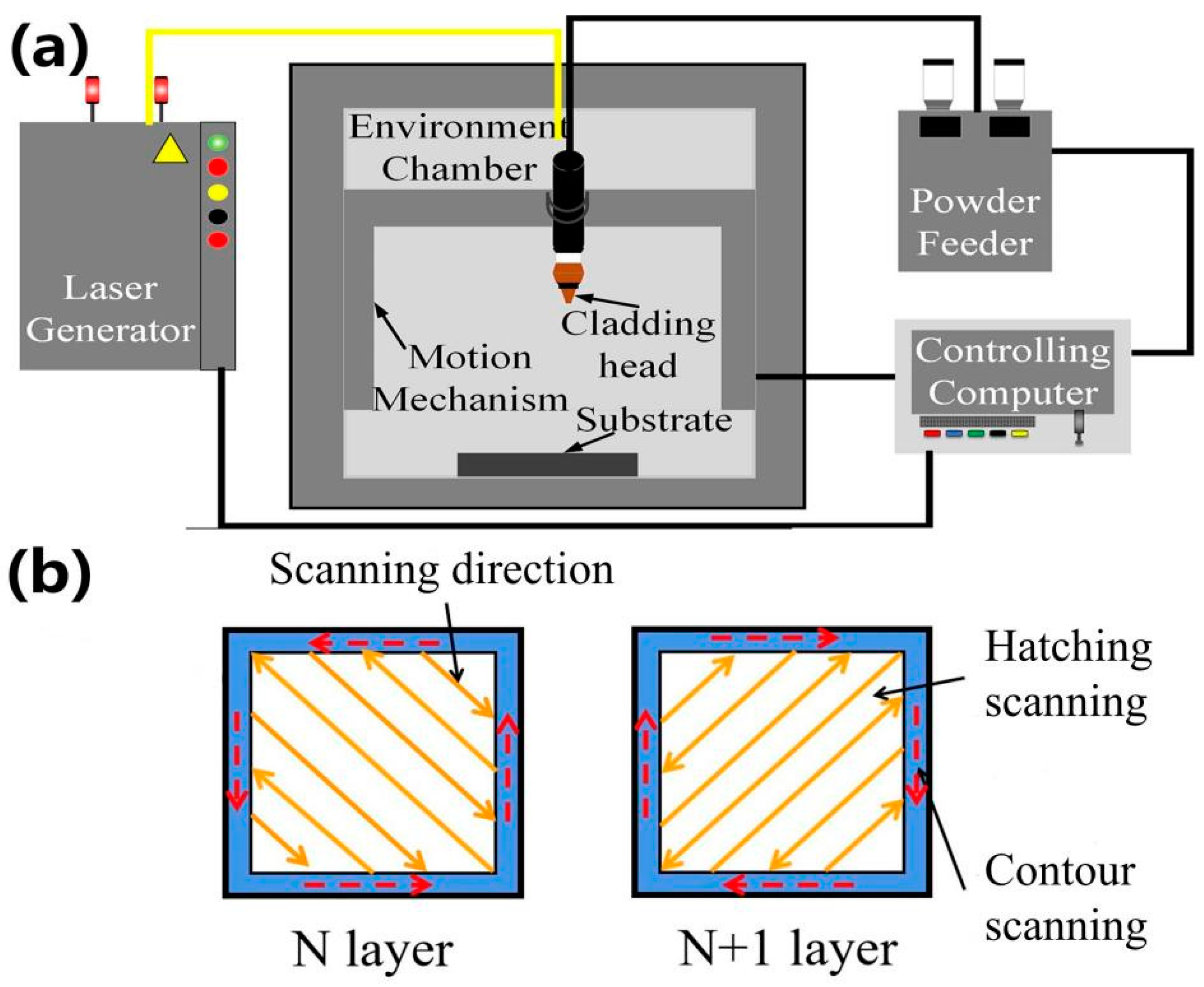
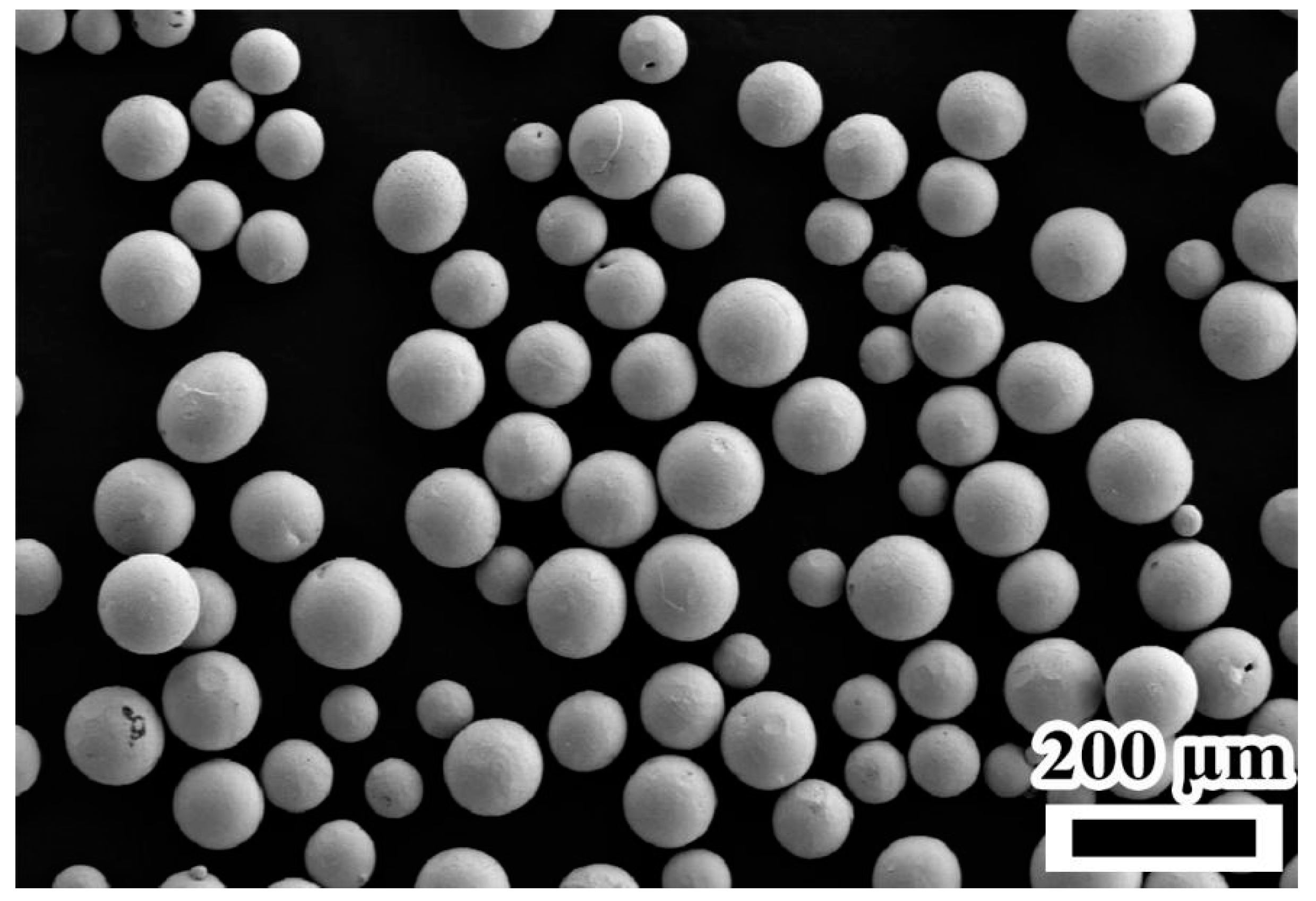
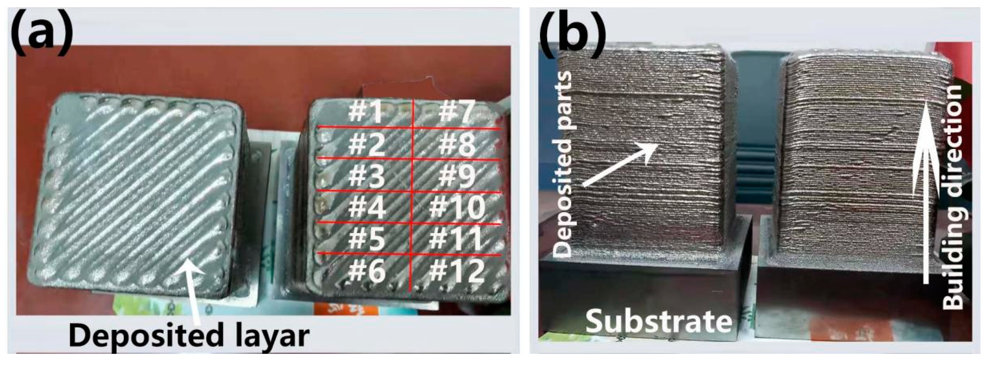
2.1. Ti-6Al-4V Block Preparation

Figure 1a shows the schematic of the additive manufacturing system, including powder feeder, fiber laser with maximum power of 10 kw and wavelength of 1070 ± 10 nm, motion mechanism, cladding head, and integrated controlling system. Ti-6Al-4V wrought plates with a dimension of 120 mm × 120 mm × 20 mm and Ti-6Al-4V commercial powder with a size distribution range from 53 μm to 150 μm (the scanning electron microscope of Ti-6Al-4V powder was shown in Figure 2) were used as substrate and powder material, respectively. The chemical composition of the powder is listed in Table 1. Before AM process, the surface of the substrate was polished and cleaned with ethanol, and the powder materials were dried in a vacuum environment with a temperature of 353.15 K for 2 h. The scanning strategy within each layer includes contour scanning and subsequent hatching scanning, which is illustrated in Figure 1b. The scanning direction between the two successive layers was kept at 90 degrees for reducing residual stress and deformation. The optimum processing parameters have been determined through previous experiments, which are listed in Table 2.

2.2. Microstructure Characterization and Annealing Treatment

Figure 3 shows the actual images of the as-built Ti-6Al-4V blocks with a dimension of 82 mm × 82 mm × 106 mm. The as-depositd Ti-6Al-4V alloy is named #0, and the corresponding number of the heat treatment state is shown in Table 3. The blocks were uniformly separated by electric discharging machining (EDM, Jiangsu Fangzheng CNC Machine, Taizhou, China) according to the numbers in Figure 3a for subsequent heat treatment. The annealing scheme is shown in Table 3, in which the nomenclature is consistent with Figure 3a. In addition, a sample cut from another Ti-6Al-4V block fabricated with identical processing parameters was chosen as reference material and will not undergo any heat treatment.
The specimens for microstructure observation were cut off from the above samples by EDM. Furthermore, according to GB/T 31310-2014, the residual stress on the surface of the deposited block was measured through the hole-drilling method. Drilling with a low-speed auger, the drilling cutting tool has a twist bit diameter of 1.5 mm, and the punch depth is set to 2 mm. The schematic diagram of the residual stress test on the plate specimen is shown in Figure 4.
Strain flower was purchased from the Zhengzhou Institute of Machinery (Zhengzhou, China), model TJ-120-1.5-Φ1.5. The strain flower dimensions are: wire grid end radius r1 = 1.75 mm, r2 = 3.25 mm; wire grid center radius of r = r1 + r2 = 2.5 mm; wire grid base length l is 1.55 mm; wire grid half-width b = 0.7275 mm. A type of static strain tester, DH3818Y, was used to measure the released strain. After drilling 2 mm and waiting for the three strain values to stabilize, the strain gauge readings were recorded at 5 min intervals, and the average of several data readings was taken as the test result and recorded as ε 1 , ε 2 , and ε 3 . Based on the obtained strain values, residual stress was calculated using the formula derived, which is as follows [16]:
σ 1 , 2 = ε 1 + ε 3 4 A 1 4 B ( ε 1 ε 3 ) 2 + ( 2 ε 3 ε 1 ε 3 ) 2
tan 2 θ = 2 ε 2 ε 1 ε 3 ε 1 ε 3  
where σ 1 and σ 2 are principal stresses, A and B are stress release coefficients, and θ is the angle between maximum principal stress and reference axis of strain gauge No. 1, clockwise.
The stress relief factor is calculated as follows:
A = 1 + u 2 E R 2 4 γ 1 γ 2
B = R 2 2 E r 1 r 2 [ 1 + 1 + u 4 R 2 ( r 1 2 + r 1 r 2 + r 2 2 ) 4 r 1 2 r 2 2 ]
where E is the modulus of elasticity of the test material, u is the Poisson’s ratio of the test material, and R , r 1 , and r 2 are hole diameter and distance from the center of the blind hole to the near and far ends of the strain gauge, respectively. For calculation, E = 110 GPa, u = 0.34, A = 0.06024 × 10⁻⁴ MPa−1, and B = −0.20003 × 10⁻⁴ MPa−1.
Subsequently, metallographic specimens were prepared according to standard procedures, including mounting and polishing. Then, the specimens were etched with an etchant (5 mL HF, 12 mL HN3O, and 83 mL H2O) for 20 s. The microstructure of the HP-LMDed Ti-6Al-4V alloy was observed under an optical microscope (OLYMPUSBX51, Tokyo, Japan), a scanning electron microscope (SEM, ZEISS Gemini 300, Jena, Germany), and a transmission electron microscope (FEI Tecnai G2 F20, Hillsboro, OR, USA). The phase composition was identified by an X-ray diffractometer (Bruker D8 Advance, Billerica, MA, USA), with a tube voltage of 40 kV, a tube current of 30 mA, a Cu target, a scanning speed of 4°/min, and a scanning range of 20–100°.

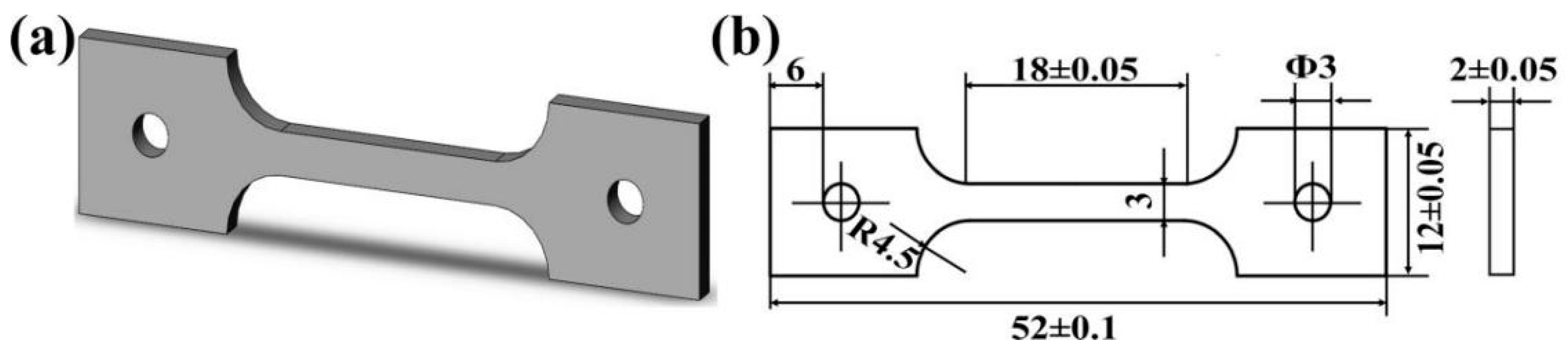
2.3. Mechanical Properties

Micro-hardness test was carried out on the surface of the metallographic specimens with a load of 1 kg and a dwelling time of 15 s. At least 30 points with a spacing of 1 mm were measured on the surface of metallographic specimens and the average value was calculated.
In order to investigate the effect of annealing on the quasi-static performance of the AMed Ti-6Al-4V alloys, miniature tensile specimens were taken from the annealed blocks by EDM. The dimension of tensile specimens is shown in Figure 5. An electronic universal testing machine (CMT5504-5105, MTS, Shenzhen, China) was used to conduct the axial tensile test at room temperature and ambient environment. Meanwhile, an extensometer with a gauge length of 8 mm was fixed on the specimen during the test to obtain an accurate value of displacement.

3. Results and Discussion

3.1. Residual Stress and Microstructure Characteristics

The residual stress within LMDed Ti-6Al-4V parts can be ascribed to the rapid melting and cooling process [17]. Although the deposited part had undergone several reheating effects, the thermal cycling was insufficient to eliminate residual stress [18]. For an LMD-fabricated Ti-6Al-4V part, the residual stress within the deposited part is mainly compressive stress, except for tensile stress at the top surface, which is similar to the selective laser melting method [11,19]. Figure 6 shows the measured residual stress on the surface of the deposited parts and the deposited parts under different annealing parameters. The residual compressive stress along the scanning direction ( σ x ) was approximately three times the residual stress along the building direction ( σ y ) on the surface of the HP-LMDed TC4. After the annealing treatment, the residual stress was reduced significantly. Under a holding time of 2 h, the residual stress decreased from 700 to 800 °C to a relatively stable level. Under a holding time of 4 h, the regulation of the microstructure had been completed at 550 °C, and the residual stress was not much different from the stable residual stress at 2 h. Anyway, as the holding temperature increases, the residual stress does not change much. Meanwhile, the difference between σ x and σ y reduced, which was consistent with Zhan’s investigation [20].
Figure 7 shows the cross-sectional morphology of the HP-LMDed Ti-6Al-4V alloy. It can be observed from Figure 7a that β columnar crystals grew along the building direction and passed through several layers. The length and width of the columnar crystals could reach several millimeters and hundreds of microns, respectively. In addition, the columnar crystals exhibited different colors under the optical microscope due to differences in crystallographic orientation within a single β columnar crystal [21]. The yellow arrow in Figure 7a is thought to represent α G B .
Figure 7b shows an enlarged view of Figure 7a. There is an obvious layer band structure. The formation of the layer band structure can be ascribed to the reheating of the previous track [22]. Figure 7c shows the microstructure under SEM. The needle-like α/α’ martensites exhibited an extremely fine structure with an average width of approximately 0.34 µm (the average width of the martensites was measured by Image-Pro Plus software). Under rapid cooling conditions, β-phases did not have enough time to transform into α-phases, leading to the formation of fine needle-like α’ martensites [23]. Meanwhile, basket-weave microstructure and pore defects (indicated by the yellow arrow in Figure 7c) can also be identified. Figure 7d shows the inver pole figure from EBSD. The α colonies within different β columnar grains had different crystallographic orientations.
Figure 8 shows the XRD pattern of the HP-LMDed Ti-6Al-4V alloy at 600 ℃ for 4 h and 800 ℃ for 2 h. The phase composition mainly consisted of α/α’ phase with a hexagonal close-packed (HCP) structure and β phase with a body-centered cubic (BCC) structure. It is difficult to distinguish the α and α’ phases from the XRD pattern since the two phases have the same crystallographic structure. It is well known that martensite transformation occurs with a cooling rate higher than 410 K/s during the solidification of the Ti-6Al-4V alloy [24]. The cooling rate of the HP-LMD process is as high as 103 K/s [25], so it is believed that the microstructure of HP-LMDed Ti-6Al-4V alloy mainly consists of α’ and β. At the same time, the position of α’ peak slightly shifted to the left due to the lattice distortion [15]. Furthermore, due to the β phase’s extremely low content, the diffraction peaks, (110) and (200), of the β phase are not obvious. In addition, the α-phase peak at 600 ℃ for 4 h is significantly higher relative to the deposited state, and the β-phase peak of the index (200) at 800 ℃ for 2 h increases, indicating an increase in β precipitation in this direction after the annealing treatment.
To further understand phase transformation during annealing treatment, the microstructure of specimen #0 and specimen #3 (the overall performance is the best) were observed under transmission electron microscopy (TEM) and the results are shown in Figure 9. For Ti-6Al-4V alloy in the deposited state, boundaries between lath martensites can be identified, which is consistent with the results reported by other researchers [23,26]. Figure 9b shows the enlarged view of the red box area in Figure 9a, and the corresponding selected area electron diffraction (SAED) patterns of zone 1 (red circle) in Figure 9c confirmed the lath consists of α phase, And the SAED of zone 2 (red circle) confirmed the gap between lath and lath consists of α and β phase. EDS mapping of the red circle regions in Figure 9b is shown inside a red dotted box, the phase between two α phases is rich in a large amount of V, and a small amount of Ti and Al elements, so it is considered as β phase. α phase consists mainly of Ti, Al, and a small number of V elements.
Figure 9e shows a bright-field micrograph of the annealed Ti-6Al-4V alloy, and Figure 9f shows the SAED patterns of the red circle regions in Figure 9e. It can be confirmed that the region contains α/α’ and β. Figure 9g shows the high-resolution image of the selected region. The boundary between α/α’ and β can be clearly distinguished in Figure 9g, and both the FFT image and IFFT image corresponding to white rectangle inFigure 9g are shown in Figure 9h. The (0002) atomic row spacing is 0.2398 nm in the grains and (110) atomic row spacing is 0.2323 nm in β grains. Therefore, the β phase can hardly be distinguished under the optical microscope due to its extremely low content, which is consistent with XRD results.
Figure 10a–f shows the microstructure of the AMed Ti-6Al-4V alloy under a holding time of 2 h. The yellow arrows show pores. After the annealing treatment under different annealing parameters, the microstructure feature exhibited no obvious variation and mainly consisted of basket-weave microstructure and α’ martensites. The average width of the martensite was obtained by randomly selecting 100 α phases and measuring its length and width with Image-Pro Plus software. The results showed that the average width of martensites in the #1 specimen to the #6 specimen was 0.410, 0.454, 0.361, 0.433, 0.507, and 0.524 μm, respectively. It was found that the average width of the martensite increased and then decreased with the increase in holding temperature under a holding time of 2 h.
Figure 10g–l shows the microstructure of the AMed Ti-6Al-4V alloy under a holding time of 4 h. The α G B can be still identified, while the population of the α colonies near the α G B boundaries reduced significantly. When the holding temperature increased from 550 °C to 800 °C, the width of the martensites was 0.357, 0.371, 0.474, 0.494, 0.616, and 0.860 μm, respectively. It can be concluded that the average width of martensites increased with the increasing holding temperature, which is different from the results of a holding time of 2 h. Martensites had enough time to grow under a holding time of 4 h, thus leading to coarsened martensites [27]. Pore defects (yellow arrows) can be identified.
For an in-depth understanding of the microstructure evolution patterns after annealing treatment, 100 groups of α/α’ phases in the SEM image were randomly selected for the length and width measurements through ImageJ-Pro Plus (version 6.0) and recorded, and the aspect ratio was calculated. Figure 11 demonstrates the relationship between the aspect ratio of martensites and the annealing process parameters. Under the holding time of 2 h, the length of α/α’ phase grew faster than the width of α/α’ phase during the process from RT to 550 ℃. The length of the α-phase changed abruptly at 600 °C, which was considered a truncation of the α-phase under different growth directions. From 600 to 700 °C, α-phase was constantly truncated with each other, and the length gradually decreased to about 4 mm, after which it was kept between 4 and 5 mm. Under the holding time of 4 h, the length of most of the α-phase at 550 °C increased during the whole annealing process, and the length of the α-phase was stabilized between 4 and 5 mm from 550 to 800 °C. It was considered that the holding time was long enough and most of α/α’ phase experienced first growth and then mutual truncation during the whole process.

3.2. Mechanical Properties

Figure 12 shows the microhardness of the HP-LMDed Ti-6Al-4V alloy under different annealing process parameters. The microhardness of all stress-relieved annealed Ti-6Al-4V alloy is larger than that of the as-deposited Ti-6Al-4V. The martensites within the as-deposited Ti-6Al-4V alloy were retained during the annealing process since the annealing temperature was located in the two-phase region [28]. In the meantime, the average hardness of all annealed specimens increased, and the highest microhardness is 356.9 HV.
Figure 13a shows the fracture surfaces of tensile specimens. The green arrows indicate the location of the tensile fracture. An obvious necking can be observed on the fracture surface of both specimens. The red area is the fracture morphology observation area and the blue area is the side fracture observation area (as shown in Section 3.3).
Figure 13b shows the comparison of the tensile performance in this study and the aviation industry standards. The horizontal asymptote and vertical asymptote represent the lower limit of yield strength (YS) and elongation according to Chinese aviation industry standards. Meanwhile, the tensile performance of the annealed specimens under a holding time of 2 h and 4 h is enclosed with a purple area and an orange area, respectively. Abnormally, specimen #12 has the lowest elongation among the annealed specimens, it is concluded that the aspect ratio in the annealing treatment is lower than six and the α phase length of the annealed Ti-6Al-4V alloy is stable and constantly widening. The elongation of other annealed specimens increased significantly compared with the specimen in an as-deposited state. In addition, the elongation of the specimens under a holding time of 2 h is larger than that of 4 h. Finally, it can be concluded that #3 presents the best match between yield strength and elongation, which is annealed under a temperature of 650 °C for 2 h.
Figure 13c,d shows the tensile performance of the annealed Ti-6Al-4V block under a holding time of 2 and 4 h. The black dashed line and the blue dashed line indicate the elongation and yield strength floor in Chinese aviation industry standards, respectively. When below either standard, the specimen failed to meet the standard and was marked purple. The YS of specimens annealed at 550 to 700 °C increased gradually. The results from the present case are different from other open pieces of the literature, in which the YS of the specimens decreased after annealing treatment [29,30]. In this present study, annealing with a holding temperature of 550 to 700 °C for 2 h can effectively reduce the residual stress along the building direction, thus leading to enhanced strength and plasticity. However, the YS of the annealed block decreased under a holding temperature of 750 and 800 °C for 4 h, and it is believed that within this temperature, the aspect ratio of the α phase is less than eight with the length changing a little and the width increasing, making the ability of α phase to block the stretching expansion weaker. In addition, it also demonstrates an aspect ratio larger than nine, which is capable of improving both yield strength and elongation. Tiley et al. [31] found, by reliable regression analysis, that the UTS and yield strength decreased with increasing thickness of α martensite. In addition, the interface of the α/β microstructure is a barrier to dislocation movement and they contribute to the yield strength of the alloy [32,33]. Therefore, during the HP-LMDed specimen block being annealed, the thin α phase grew continuously, and the different growth directions truncated each other to produce more α/β interfaces, which can improve yield strength and elongation at the same time to a certain extent.
It can be observed that the YS decreased with the increasing holding temperature under a holding time of 4 h. It is believed that the degree of grain coarsening increases with the increase in annealing temperature, which consequently leads to a decreased strength [28]. The α’ martensites transform into the basket-weave microstructure during the annealing process. The basket-weave microstructure can reduce the stacking of dislocations, and improve plasticity. These things considered, the existence of α colonies near α G B usually causes local stress concentrations, leading to the formation of microcracks and deteriorating the tensile properties. After the annealing treatment, the induced stress concentration was alleviated and the plasticity of annealed specimens is significantly better than that of the as-deposited Ti-6Al-4V alloy. Therefore, the YS of the annealed Ti-6Al-4V block decreased with the increasing annealing temperatures [34].

3.3. Fracture Mechanism

Figure 14 shows the fracture morphology of specimens #0 and #3. It can be observed from Figure 14a,b that the fracture surface of both specimens exhibits an irregular morphology and a large number of deep grooves can be found on the fracture surface. The irregularity of the fracture surface may be attributed to the destruction of metallurgical bonding between layers [35]. Figure 14e shows the enlarged view in the yellow rectangle of Figure 14a. The fracture morphology is dominated by dimples with different sizes, which indicates the superior plasticity of the HP-LMDed Ti-6Al-4V alloy. Figure 14f shows the enlarged view in the yellow rectangle of Figure 14b. The dimples of specimen #3 are larger than that of specimen #0, which indicates that specimen #3 has superior plasticity. The fracture analysis is consistent with the results of the tensile test.
To further investigate the tensile properties of the annealed Ti-6Al-4V alloy, the side fracture of specimens #0 and #3 was observed under scanning electron microscopy. Figure 14c,d shows the macro-morphology and lateral morphology of the fractured specimens. The red dashed lines represent the α G B . It can be found that the fracture mechanism is dominated by a transgranular fracture, and un-melted powders can also be observed on the lateral surface. During tensile testing, the unevenness of the strain between α/α’ phase and β phase led to the formation of micro-cavities at the α/β interface, resulting in the aggregation of micro-pores and subsequent formation of microcracks [36]. The white dashed line indicates the direction of the phase in Figure 14g,h (the enlarged view in the white rectangle of Figure 14c,d). These things considered, as-deposited Ti-6Al-4V alloy requires more energy for the crack to pass vertically due to its long and thin feature of α phase. Otherwise, the crack turns in this region to continue its expansion forward. Whereas the α phase in the annealed blocks becomes shorter and thicker, the threshold value for crack forward extension is reduced, and a 45° tensile fracture is formed due to its plasticity.

4. Conclusions

In the present work, several Ti-6Al-4V blocks were successfully fabricated by high-power laser melting deposition (HP-LMD). The effects of the annealing temperature and annealing holding time on the microstructure evolution, residual stress, and mechanical properties of the fabricated block were investigated. The following conclusions can be drawn:
(1)
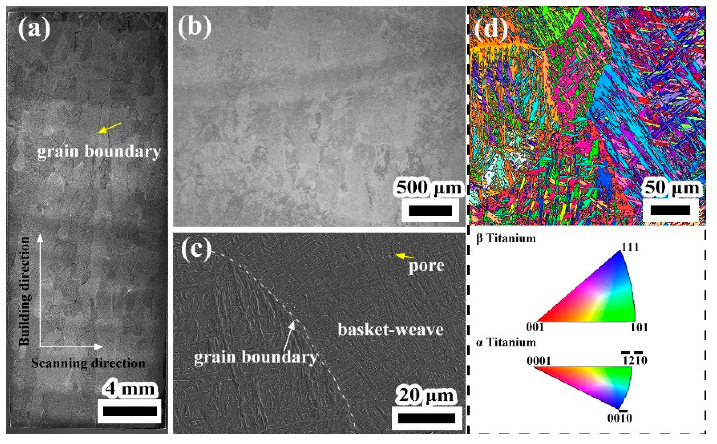
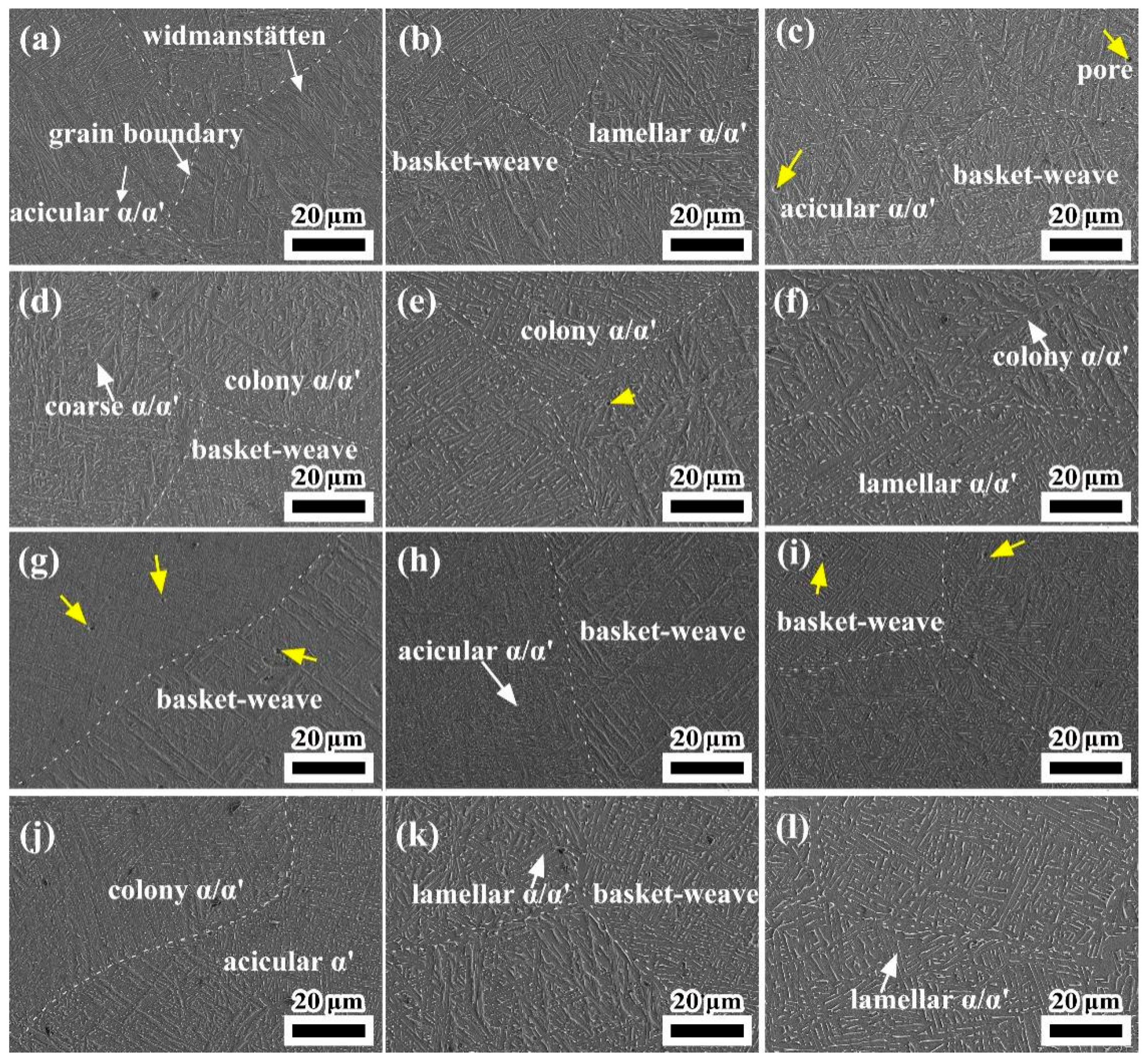
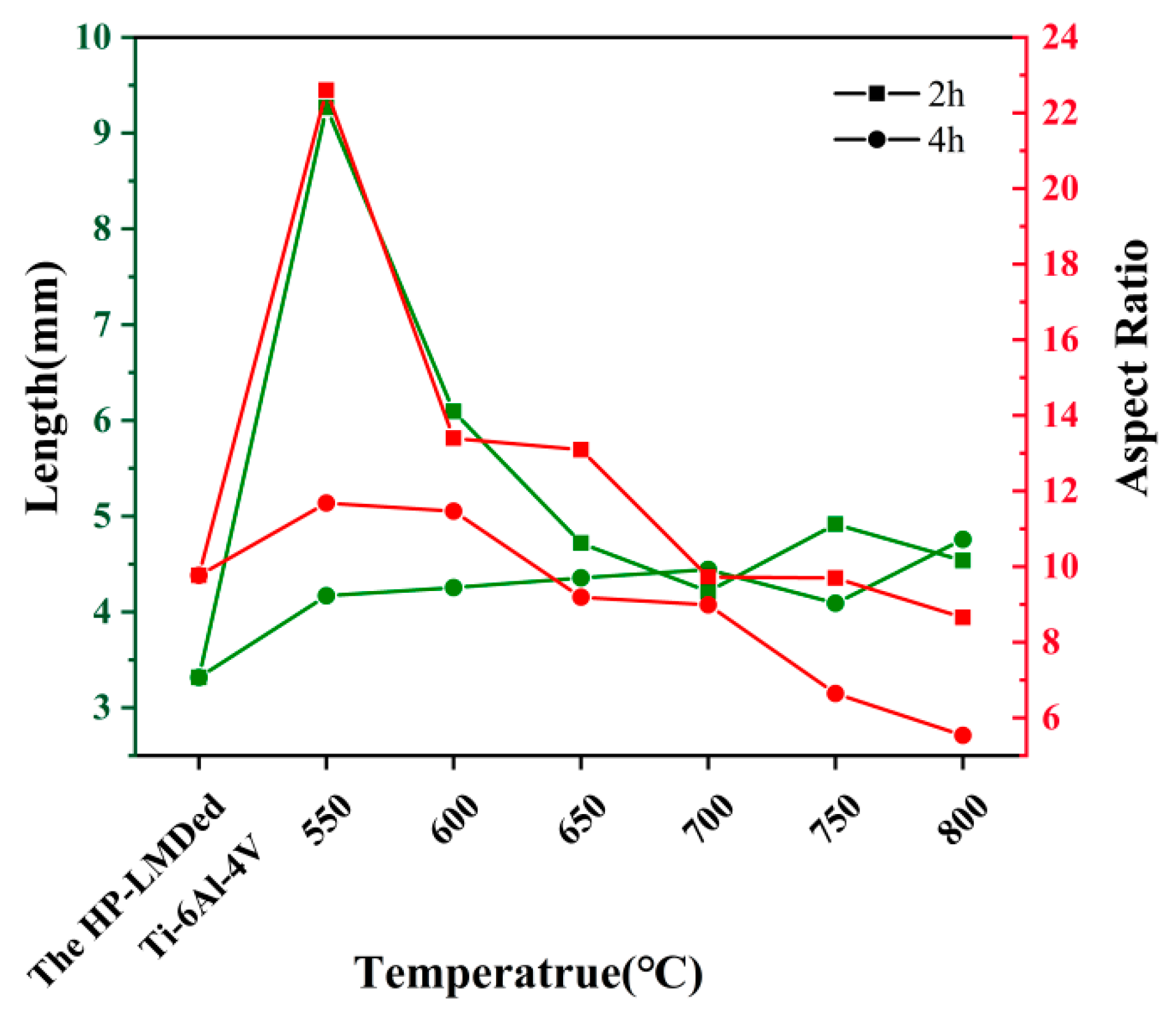
The width of α’ martensite within the as-deposited Ti-6Al-4V alloy was 0.340 μm, while the width of α’ martensite of all the annealed specimens was larger. In the meantime, the aspect ratio of α’ martensite decreased with the increase in annealing temperature and annealing holding time;
(2)
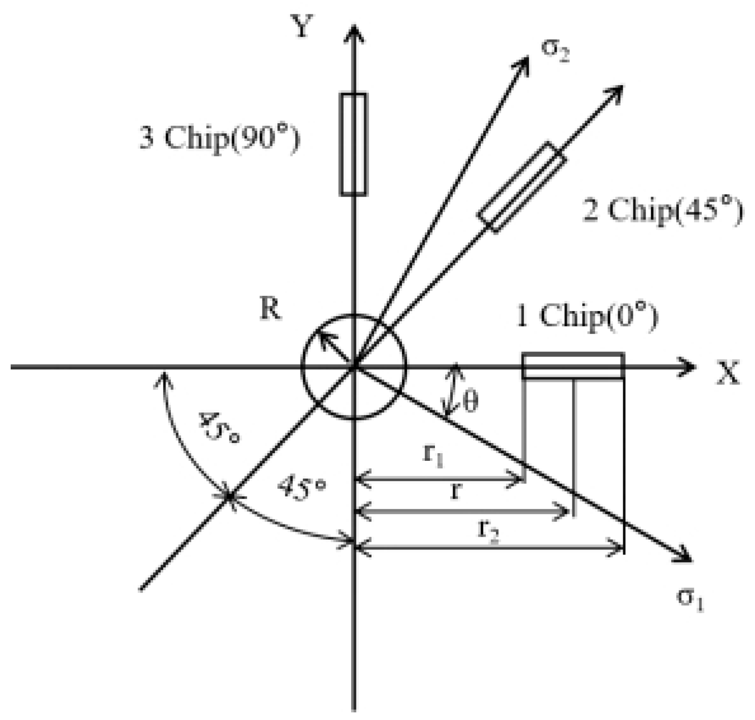
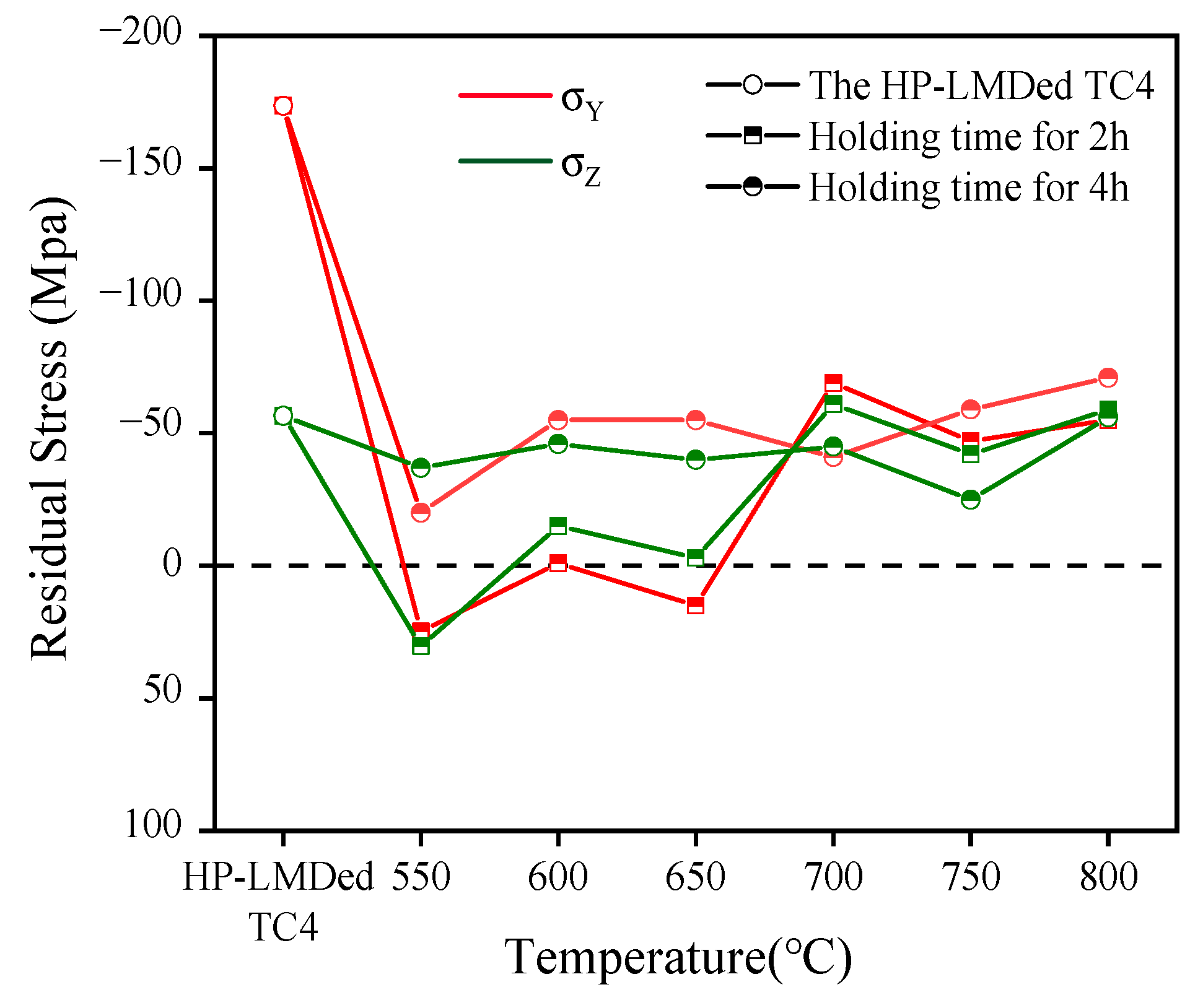
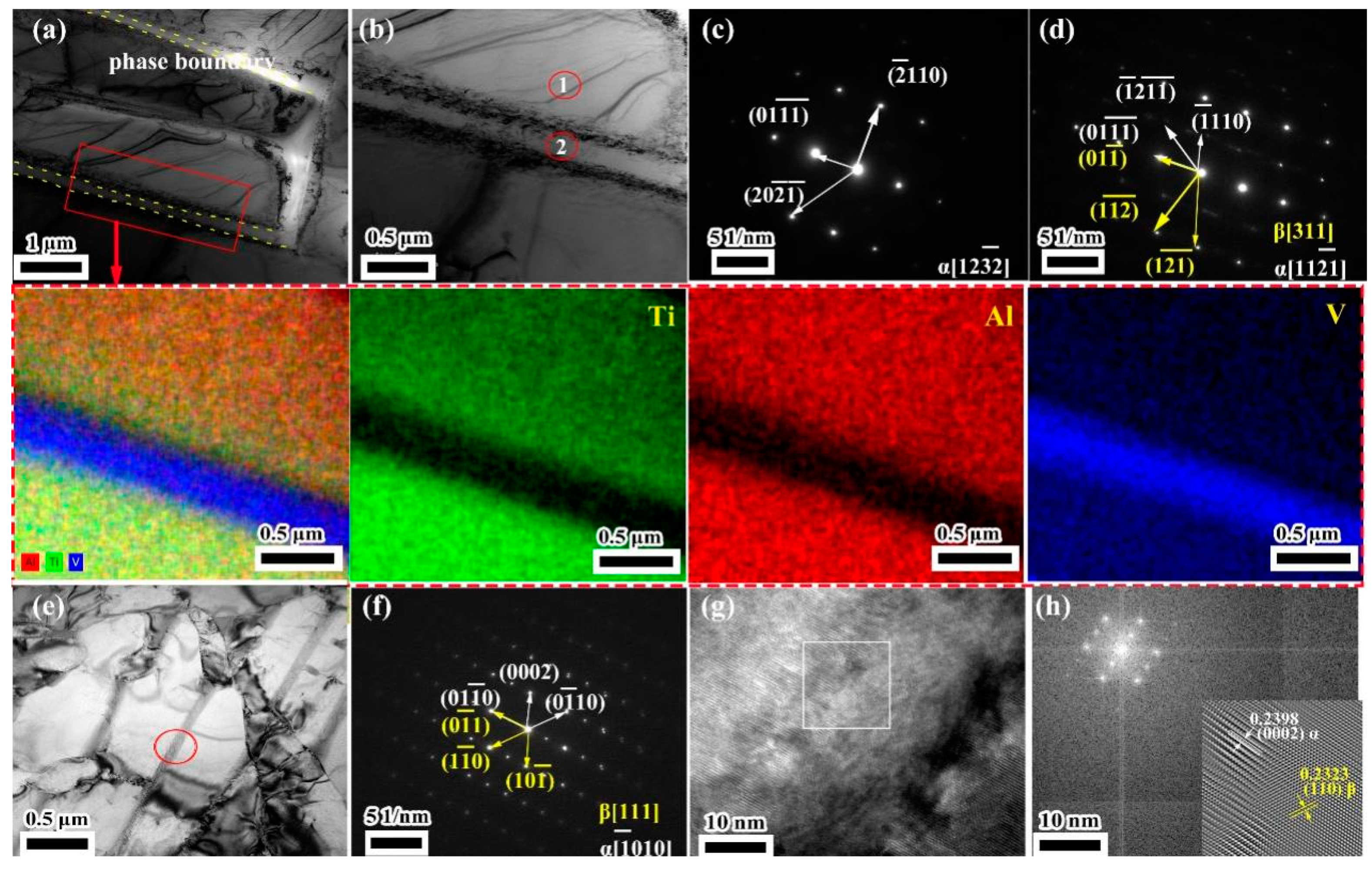
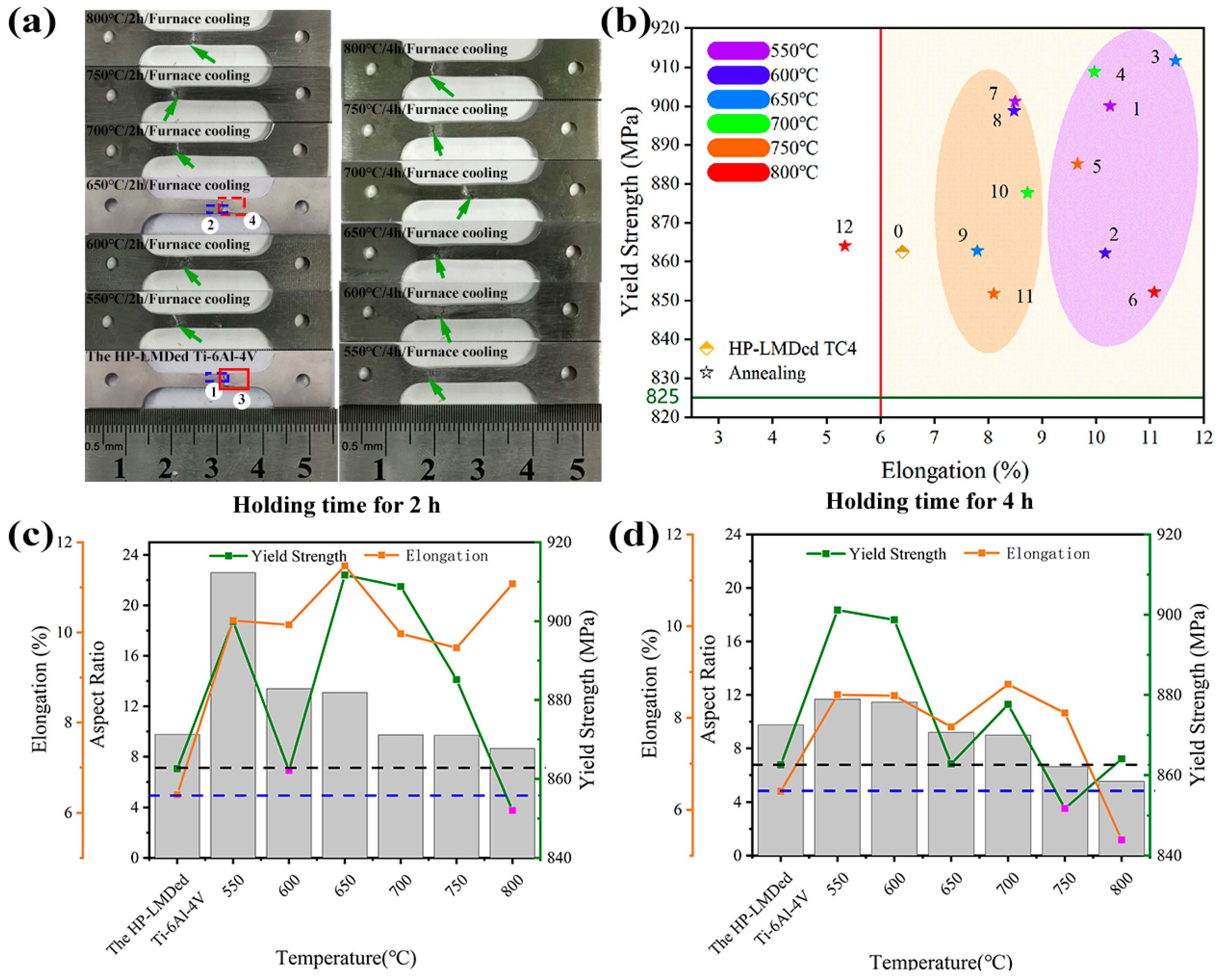
For the as-deposited Ti-6Al-4V block, the residual compressive stress along the scanning direction was approximately three times the residual stress along the building direction. After the annealing treatments with different parameters, the residual compressive stress on the surface of the deposited block reduced significantly or even turned into residual tensile stress. The optimum annealing process was annealing at 650 °C for 2 h, in which the residual stress along the scanning direction and the building direction was reduced by 91.36% and 94.70%, respectively;
(3)
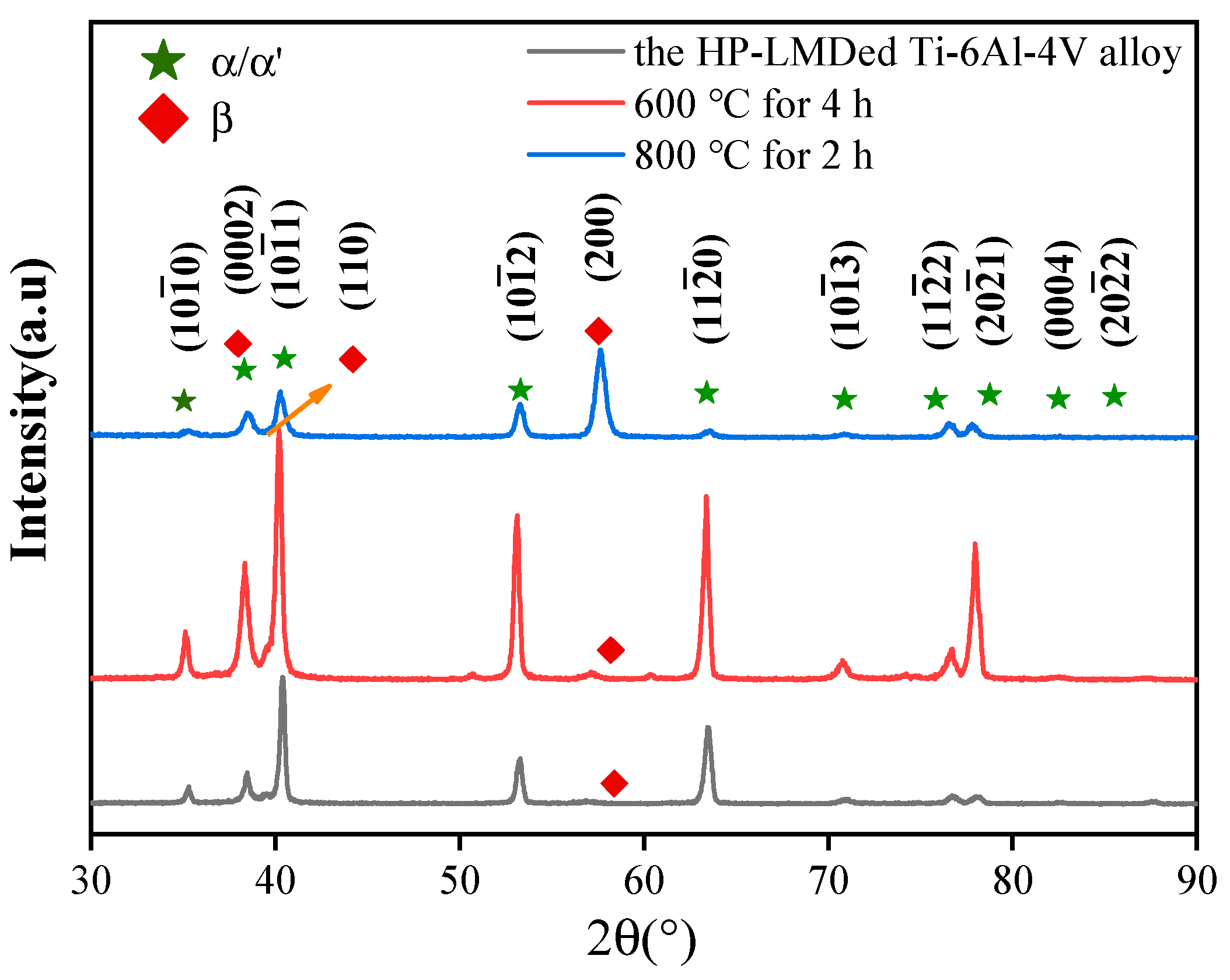
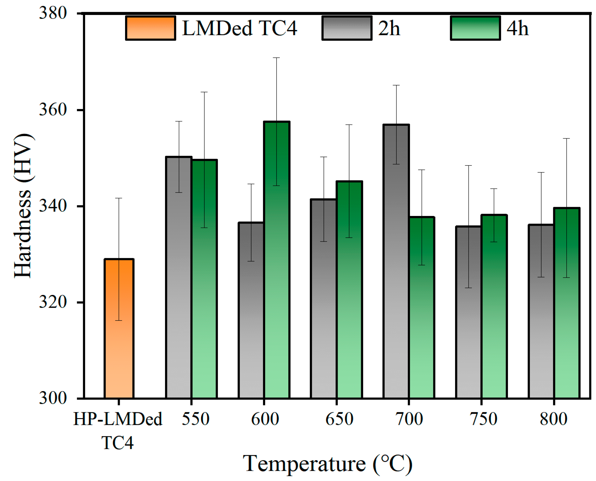
The microhardness of all annealed specimens was higher than that of as-deposited Ti-6Al-4V alloy. The microstructure of the annealed samples mainly consisted of α/α’ martensite and basket-weave microstructure. As a result, the microhardness of annealed samples with different annealing parameters showed little variation;
(4)
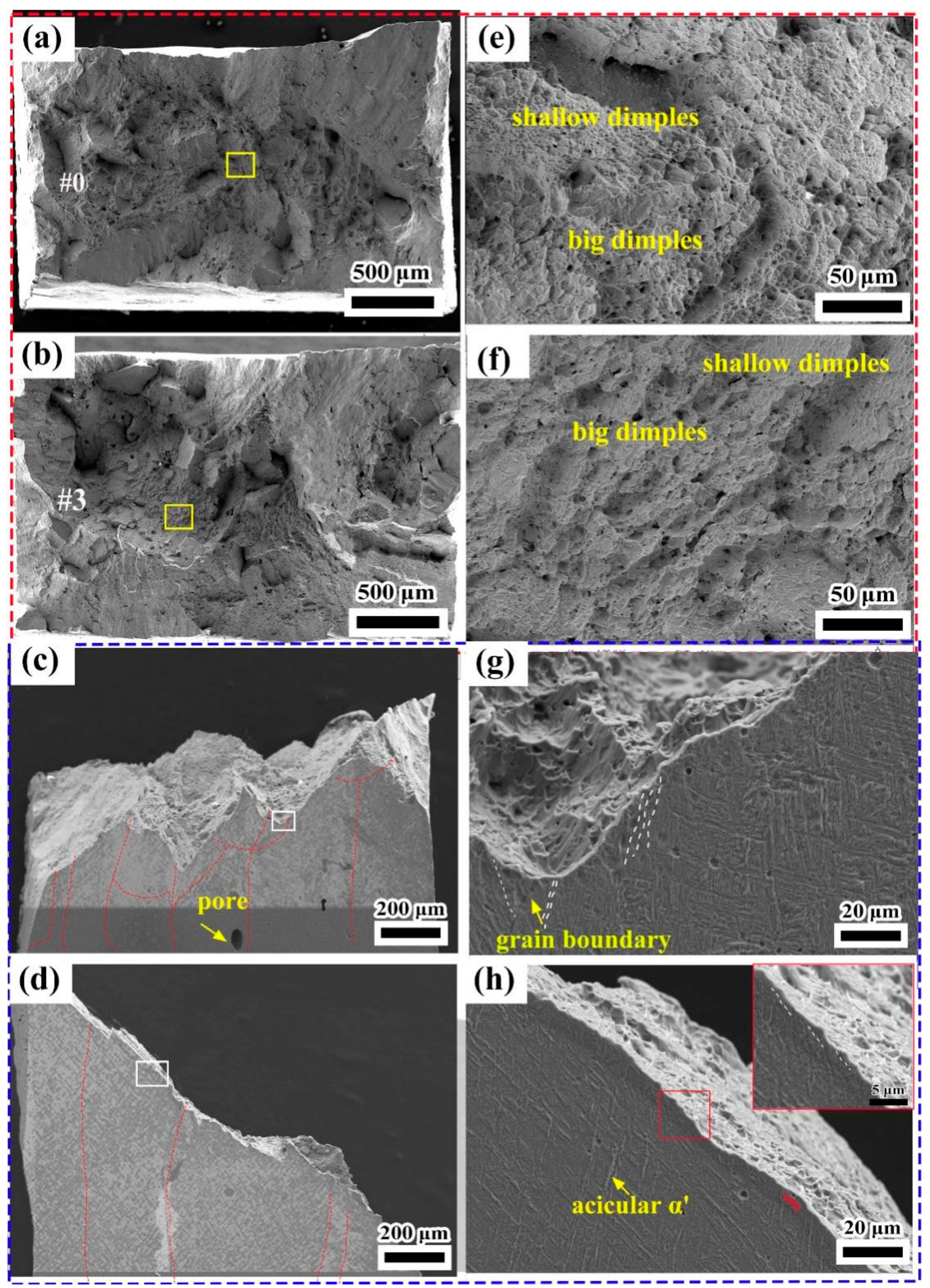
The sample annealed with a temperature of 650 °C for 2 h presented the best tensile performance, with a yield strength of 912 MPa and an elongation of 11.48%. The YS and elongation of α/α’ phase are better than those of the deposited state when the aspect ratio of the α phase is in the range of 9 to 14. The fracture surface of both the as-deposited samples and annealed samples was dominated by dimples with different sizes. Meanwhile, samples processed by the optimum annealing treatment exhibited larger dimples than that of the as-deposited sample from fractography analysis, which indicated superior plasticity after annealing treatment.

Author Contributions

Conceptualization, H.C. and Y.L.; methodology, Z.Z. and Y.C.; software, S.X.; validation, S.T., Y.C. and J.L.; formal analysis, Y.C.; investigation, Y.C.; resources, H.C.; data curation, Y.C.; writing—original draft preparation, Y.C.; writing—review and editing, Y.C., H.L.; visualization, Y.C. and Z.Z.; supervision, Z.Z.; project administration, Y.L. and H.C.; funding acquisition, Z.Z. and Y.L. All authors have read and agreed to the published version of the manuscript.

Funding

This work was financially supported by the National Natural Science Foundation of China (52205419), the China Postdoctoral Science Foundation (2022M712637), and the Sichuan Science and Technology Program (2022YFG0101).

Institutional Review Board Statement

Not applicable.

Informed Consent Statement

Not applicable.

Data Availability Statement

The raw/processed data required to reproduce these findings are available from the corresponding author upon reasonable request.

Acknowledgments

We are also grateful to the Shiyanjia Lab (www.shiyanjia.com) for the SEM analysis and the Analysis Center of Tsinghua University for supporting the TEM measurements.

Conflicts of Interest

The authors declare no conflict of interest.

References

  1. Tshephe, T.S.; Akinwamide, S.O.; Olevsky, E.; Olubambi, P.A. Additive manufacturing of titanium-based alloys- A review of methods, properties, challenges, and prospects. Heliyon 2022, 8, e9041. [Google Scholar] [CrossRef] [PubMed]
  2. Lv, H.; Zhang, Z.; Chen, Y.; Liu, Y.; Chen, H.; Cheng, J.; She, J.; He, H.; Chen, J. The anisotropy of high cycle fatigue property and fatigue crack growth behavior of Ti–6Al–4V alloy fabricated by high-power laser metal deposition. Mater. Sci. Eng. A 2022, 853, 143745. [Google Scholar] [CrossRef]
  3. Chen, J.; Li, H.; Liu, Y.; Zhao, X.; Cai, Y.; Chen, H.; Chen, Y.; Feng, A.; Wang, H.; Sun, Z. Deformation Behavior and Microstructure Characteristics of the Laser-Welded Ti-6Al-4V Joint under Variable Amplitude Fatigue. Mater. Charact. 2023, 196, 112606. [Google Scholar] [CrossRef]
  4. Zhang, Y.; Xi, M.; Gao, S.; Shi, L. Characterization of laser direct deposited metallic parts. J. Mater. Process. Technol. 2003, 142, 582–585. [Google Scholar] [CrossRef]
  5. Azarniya, A.; Colera, X.G.; Mirzaali, M.J.; Sovizi, S.; Bartolomeu, F.; St Weglowski, M.K.; Wits, W.W.; Yap, C.Y.; Ahn, J.; Miranda, G.; et al. Additive manufacturing of Ti–6Al–4V parts through laser metal deposition (LMD): Process, microstructure, and mechanical properties. J. Alloy. Comp. 2019, 804, 163–191. [Google Scholar]
  6. Ren, Y.; Lin, X.; Yang, H.; Tan, H.; Chen, J.; Jian, Z.; Li, J.; Huang, W. Microstructural features of Ti-6Al-4V manufactured via high power laser directed energy deposition under low-cycle fatigue. J. Mater. Sci. Technol. 2021, 83, 18–33. [Google Scholar] [CrossRef]
  7. Zhai, Y.; Lados, D.A.; Brown, E.J.; Vigilante, G.N. Understanding the microstructure and mechanical properties of Ti-6Al-4V and Inconel 718 alloys manufactured by Laser Engineered Net Shaping. Addit. Manuf. 2019, 27, 334–344. [Google Scholar] [CrossRef]
  8. Svetlizky, D.; Das, M.; Zheng, B.; Vyatskikh, A.L.; Bose, S.; Bandyopadhyay, A.; Schoenung, J.M.; Lavernia, E.J.; Eliaz, N. Directed energy deposition (DED) additive manufacturing: Physical characteristics, defects, challenges and applications. Mater. Today 2021, 49, 271–295. [Google Scholar] [CrossRef]
  9. Karpenko, O.; Oterkus, S.; Oterkus, E. Investigating the influence of residual stresses on fatigue crack growth for additively manufactured titanium alloy Ti6Al4V by using peridynamics. Int. J. Fatigue 2021, 155, 106624. [Google Scholar] [CrossRef]
  10. Zhan, Y.; Liu, C.; Zhang, J.J.; Mo, G.Z.; Liu, C.S. Measurement of residual stress in laser additive manufacturing TC4 titanium alloy with the laser ultrasonic technique. Mater. Sci. Eng. A 2019, 762, 138093. [Google Scholar] [CrossRef]
  11. Chauhan, A.K.S.; Shukla, M. Residual Stress Modeling and Simulation of Direct Metal Laser Sintered Ti-6Al-4V Alloy. Mater. Today Proc. 2019, 18, 5189–5195. [Google Scholar] [CrossRef]
  12. Ding, X.; Ma, H.; Zhang, Q.; Yang, J.; Li, D.; Fan, S. Effect of annealing heat treatment on microstructure and corrosion behavior of Ti6Al4V alloy fabricated by multi-laser beam wire-feed additive manufacturing in vacuum environment. J. Alloy. Compd. 2022, 914, 165363. [Google Scholar] [CrossRef]
  13. Dolgun, E.; Zemlyakov, E.; Shalnova, S.; Gushchina, M.; Promahov, V. The influence of heat treatment on the microstructure of products manufactured by direct laser deposition using titanium alloy Ti-6Al-4V. Mater. Today Proc. 2020, 30, 688–693. [Google Scholar] [CrossRef]
  14. Xu, X.; Liu, Q.; Wang, J.; Ren, X.; Hou, H. The heat treatment improving the mechanical and fatigue property of TA15 alloy joint by friction stir welding. Mater. Charact. 2021, 180, 111399. [Google Scholar] [CrossRef]
  15. Ye, H.; Le, F.; Wei, C.; Ye, K.; Liu, S.; Wang, G. Fatigue crack growth behavior of Ti-6Al-4V alloy fabricated via laser metal deposition: Effects of building orientation and heat treatment. J. Alloy. Compd. 2021, 868, 159023. [Google Scholar] [CrossRef]
  16. Wu, T.; Degener, S.; Tinkloh, S.; Liehr, A.; Zinn, W.; Nobre, J.; Tröster, T.; Niendorf, T. Characterization of residual stresses in fiber metal laminate interfaces—A combined approach applying hole-drilling method and energy-dispersive X-ray diffraction. Compos. Struct. 2022, 299, 116071. [Google Scholar] [CrossRef]
  17. Brandl, E.; Michailov, V.; Viehweger, B.; Leyens, C. Deposition of Ti–6Al–4V using laser and wire, part II: Hardness and dimensions of single beads. Surf. Coatings Technol. 2011, 206, 1130–1141. [Google Scholar] [CrossRef]
  18. Bartlett, J.L.; Li, X. An overview of residual stresses in metal powder bed fusion. Addit. Manuf. 2019, 27, 131–149. [Google Scholar] [CrossRef]
  19. Machirori, T.; Liu, F.; Yin, Q.; Wei, H. Spatiotemporal variations of residual stresses during multi-track and multi-layer deposition for laser powder bed fusion of Ti-6Al-4V. Comput. Mater. Sci. 2021, 195, 110462. [Google Scholar] [CrossRef]
  20. Zhan, Y.; Xu, H.; Du, W.; Liu, C. Research on the influence of heat treatment on residual stress of TC4 alloy produced by laser additive manufacturing based on laser ultrasonic technique. Ultrasonics 2021, 115, 106466. [Google Scholar] [CrossRef]
  21. Choi, Y.R.; Sun, S.D.; Liu, Q.; Brandt, M.; Qian, M. Influence of deposition strategy on the microstructure and fatigue properties of laser metal deposited Ti-6Al-4V powder on Ti-6Al-4V substrate. Int. J. Fatigue 2019, 130, 105236. [Google Scholar] [CrossRef]
  22. Brandl, E.; Schoberth, A.; Leyens, C. Morphology, microstructure, and hardness of titanium (Ti-6Al-4V) blocks deposited by wire-feed additive layer manufacturing (ALM). Mater. Sci. Eng. A 2012, 532, 295–307. [Google Scholar] [CrossRef]
  23. Xing, L.-L.; Zhang, W.-J.; Zhao, C.-C.; Gao, W.-Q.; Shen, Z.-J.; Liu, W. Influence of Powder Bed Temperature on the Microstructure and Mechanical Properties of Ti-6Al-4V Alloy Fabricated via Laser Powder Bed Fusion. Materials 2021, 14, 2278. [Google Scholar] [CrossRef] [PubMed]
  24. Ahmed, T.; Rack, H.J. Phase transformations during cooling in α + β titanium alloys. Mater. Sci. Eng. A 1998, 243, 206–211. [Google Scholar] [CrossRef]
  25. Bertoli, U.S.; Guss, G.; Wu, S.; Matthews, M.J.; Schoenung, J.M. In-situ characterization of laser-powder interaction and cooling rates through high-speed imaging of powder bed fusion additive manufacturing. Mater. Des. 2017, 135, 385–396. [Google Scholar] [CrossRef]
  26. He, J.; Li, D.; Jiang, W.; Ke, L.; Qin, G.; Ye, Y.; Qin, Q.; Qiu, D. The Martensitic Transformation and Mechanical Properties of Ti6Al4V Prepared via Selective Laser Melting. Materials 2019, 12, 321. [Google Scholar] [CrossRef] [Green Version]
  27. Liu, J.; Zhang, K.; Yang, Y.; Wang, H.; Zhu, Y.; Huang, A. Grain boundary α-phase precipitation and coarsening: Comparing laser powder bed fusion with as-cast Ti-6Al-4V. Scr. Mater. 2021, 207, 114261. [Google Scholar] [CrossRef]
  28. Bai, H.; Deng, H.; Chen, L.; Liu, X.; Qin, X.; Zhang, D.; Liu, T.; Cui, X. Effect of Heat Treatment on the Microstructure and Mechanical Properties of Selective Laser-Melted Ti64 and Ti-5Al-5Mo-5V-1Cr-1Fe. Metals 2021, 11, 534. [Google Scholar] [CrossRef]
  29. Sun, W.; Ma, Y.E.; Li, P.; Wang, Z. Residual stress and long fatigue crack growth behaviour of laser powder bed fused Ti6Al4V: Role of build direction. Int. J. Fatigue 2022, 160, 106850. [Google Scholar] [CrossRef]
  30. Vrancken, B.; Cain, V.; Knutsen, R.; Van Humbeeck, J. Residual stress via the contour method in compact tension specimens produced via selective laser melting. Scr. Mater. 2014, 87, 29–32. [Google Scholar] [CrossRef] [Green Version]
  31. Tiley, T.J.; Searles, T.; Lee, E.; Kar, S.; Banerjee, R.; Russ, J.C.; Fraser, H.L. Quantification of microstructural features in α/β titanium alloys. Mater. Sci. Eng. A. 2004, 372, 191–198. [Google Scholar] [CrossRef]
  32. Su, J.; Ji, X.; Liu, J.; Teng, J.; Jiang, F.; Fu, D.; Zhang, H. Revealing the decomposition mechanisms of dislocations and metastable α’ phase and their effects on mechanical properties in a Ti-6Al-4V alloy. J. Mater. Sci. Technol. 2021, 107, 136–148. [Google Scholar] [CrossRef]
  33. Ahluwalia, R.; Laskowski, R.; Ng, N.; Wong, M.; Quek, S.S.; Wu, D.T. Phase field simulation of α/β microstructure in titanium alloy welds. Mater. Res. Express. 2020, 7, 046517. [Google Scholar] [CrossRef]
  34. Zhao, Z.; Chen, J.; Lu, X.; Tan, H.; Lin, X.; Huang, W. Formation mechanism of the α variant and its influence on the tensile properties of laser solid formed Ti-6Al-4V titanium alloy. Mater. Sci. Eng. A 2017, 691, 16–24. [Google Scholar] [CrossRef]
  35. Chang, K.; Liang, E.; Huang, W.; Zhang, X.; Chen, Y.; Dong, J.; Zhang, R. Microstructural feature and mechanical property in different building directions of additive manufactured Ti6Al4V alloy. Mater. Lett. 2020, 267, 127516. [Google Scholar] [CrossRef]
  36. Simonelli, M.; Tse, Y.; Tuck, C. Effect of the build orientation on the mechanical properties and fracture modes of SLM Ti–6Al–4V. Mater. Sci. Eng. A 2014, 616, 1–11. [Google Scholar] [CrossRef]
Figure 1. (a) The layout of the high-power laser melting deposition (HP-LMD) system; (b) the scanning strategy.
Coatings 13 00202 g001
Figure 2. The scanning electron microscope of Ti-6Al-4V powder.
Coatings 13 00202 g002
Figure 3. The HP-LMDed Ti-6Al-4V blocks: (a) top view; (b) front view.
Coatings 13 00202 g003
Figure 4. The schematic diagram of the residual stress test on the plate specimen.
Coatings 13 00202 g004
Figure 5. The dimension of the tensile specimen (mm). (a) three-dimensional schematic diagram; (b) geometry and dimensions.
Coatings 13 00202 g005
Figure 6. The residual stress on the surface of the deposited parts and the AMed parts under different annealing process parameters.
Coatings 13 00202 g006
Figure 7. The microstructure of HP-LMDed Ti-6Al-4V alloy: (a) stereomicroscope; (b) optical microscope; (c) scanning electron microscope; (d) inver pole figure from electron backscattered diffraction (EBSD).
Coatings 13 00202 g007
Figure 8. XRD pattern of the HP-LMDed Ti-6Al-4V alloy at 600 ℃ for 4 h and 800 ℃ for 2 h.
Coatings 13 00202 g008
Figure 9. The TEM micrographs of the HP-LMDed Ti-6Al-4V alloy: (a) bright-field image in the deposited state and EDS mapping of the red regions in (a); (b) enlarged view of (a); (c) SAED patterns of zone 1 in (b); (d) SAED patterns of zone 2 in (b); (e) bright-field image in the annealed state; (f) SAED patterns of the red circle regions in (e); (g) the high-resolution image of the selected region in (e); (h) FFT image and HRTEM IFFT image of the white region in (g).
Coatings 13 00202 g009
Figure 10. The microstructure of the HP-LMDed Ti-6Al-4V alloy under different annealing parameters: (af) specimen #1 to #6 (holding time for 2 h) under OM; (gl) specimen #7 to #12 (holding time for 4 h) under SEM.
Coatings 13 00202 g010
Figure 11. The relationship between martensite size and annealing process parameters.
Coatings 13 00202 g011
Figure 12. The microhardness of the HP-LMDed Ti-6Al-4V alloy under different annealing process parameters.
Coatings 13 00202 g012
Figure 13. The tensile performance of the annealed specimens: (a) the fracture surfaces of tensile specimens; (b) the comparison of the tensile performance in this present study and the aviation industry standards; (c) the relation between aspect ratio and tensile performance under a holding time of 2 h; (d) the relation between aspect ratio and tensile performance under a holding time of 4 h.
Coatings 13 00202 g013
Figure 14. The tensile fracture surfaces of: (a) specimen #0, (e) enlarged view in (a); (b) specimen #3, (f) enlarged view in (b); (c) lateral view of specimen #0, (g) enlarged view in (c); (d) lateral view of specimen #3, (h) enlarged view in (d).
Coatings 13 00202 g014
Table 1. The chemical composition of Ti-6Al-4V powder (wt.%).
AlVFeCNHOTi
6.113.970.300.0050.0060.00280.062Bal.
Table 2. The optimum processing parameters of the HP-LMD process.
Laser Power
(W)
Scanning
Speed
(mm/min)
Powder
Feeding Rate
(g/min)
Spot
Diameter
(mm)
Overlapping
Ratio
(%)
5000100031750
Table 3. The annealing scheme.
No.Temperature (°C)Holding Time (h)Cooling Condition
#0\\\
#15502Furnace Cooling
#26002Furnace Cooling
#36502Furnace Cooling
#47002Furnace Cooling
#57502Furnace Cooling
#68002Furnace Cooling
#75504Furnace Cooling
#86004Furnace Cooling
#96504Furnace Cooling
#107004Furnace Cooling
#117504Furnace Cooling
#128004Furnace Cooling
Disclaimer/Publisher’s Note: The statements, opinions and data contained in all publications are solely those of the individual author(s) and contributor(s) and not of MDPI and/or the editor(s). MDPI and/or the editor(s) disclaim responsibility for any injury to people or property resulting from any ideas, methods, instructions or products referred to in the content.

