
Effects of Process Parameters on Microstructure and High-Temperature Oxidation Resistance of Laser-Clad IN718 Coating on Cr5Mo Steel


Abstract
:1. Introduction
2. Materials and Methods
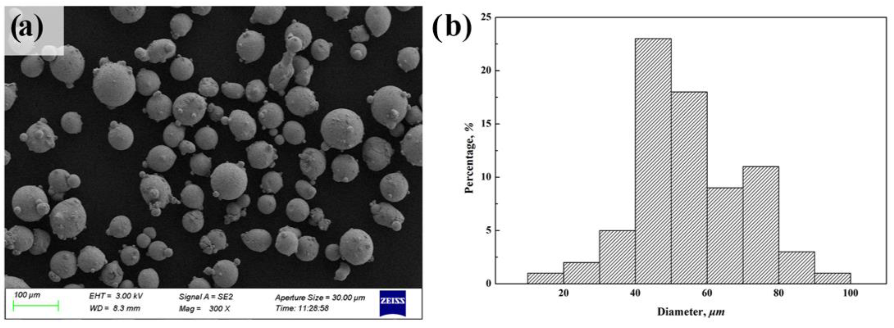
2.1. Substrate and Laser Cladding Powder
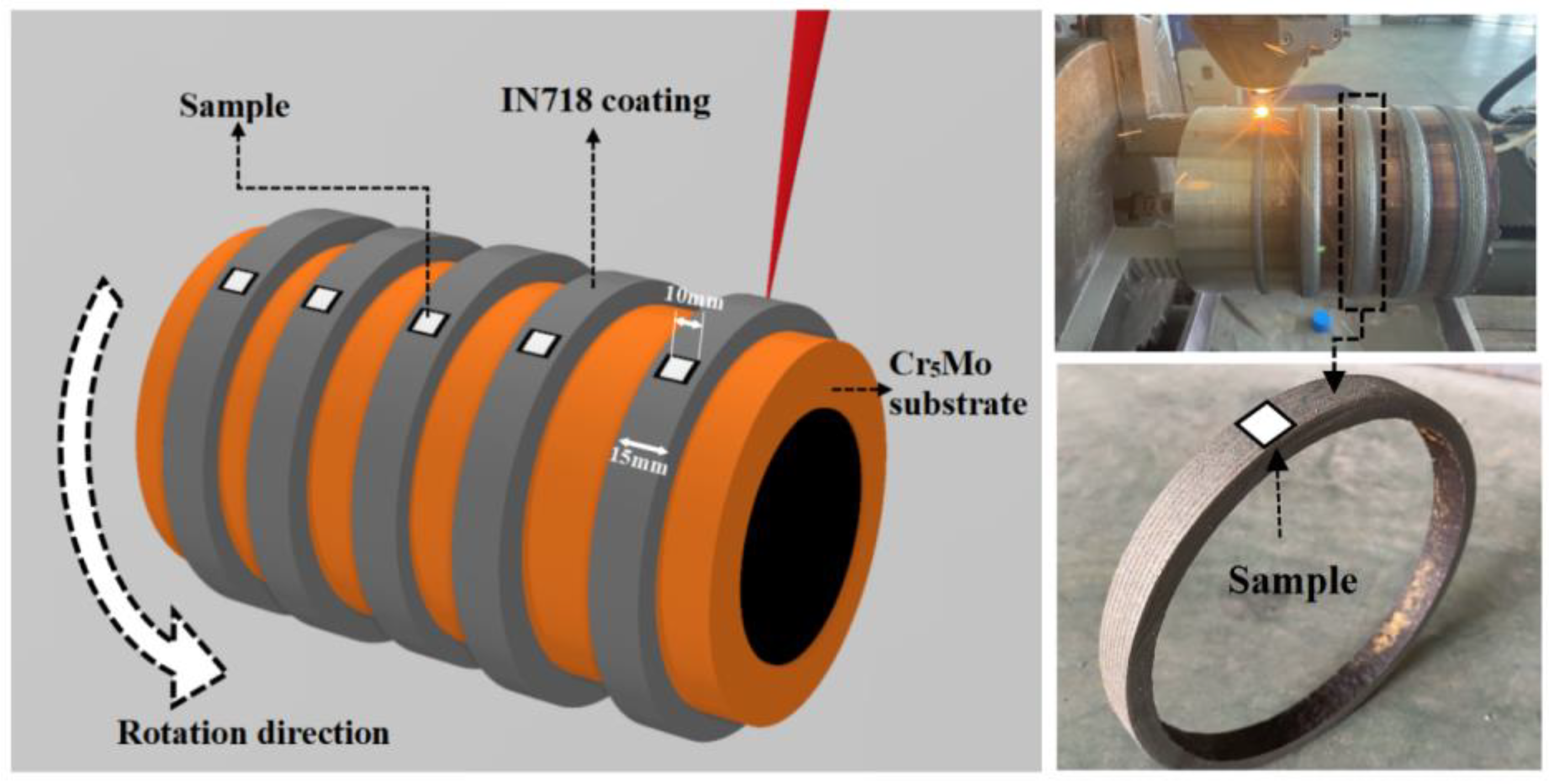
2.2. Preparation of Laser Cladding Layer and Test Sample
2.3. Analysis and Testing
3. Results
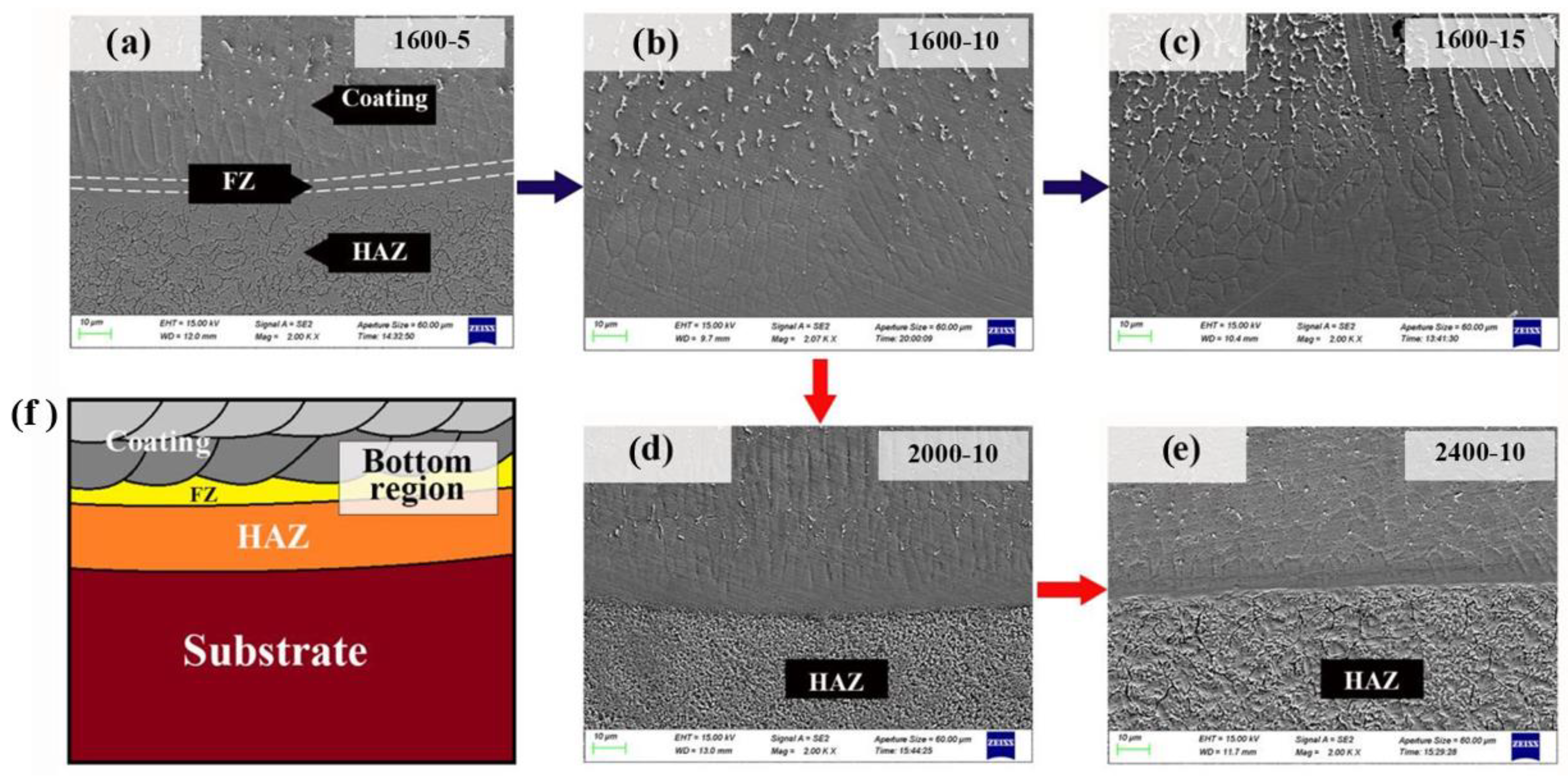
3.1. Microstructure
3.2. Hardness Testing
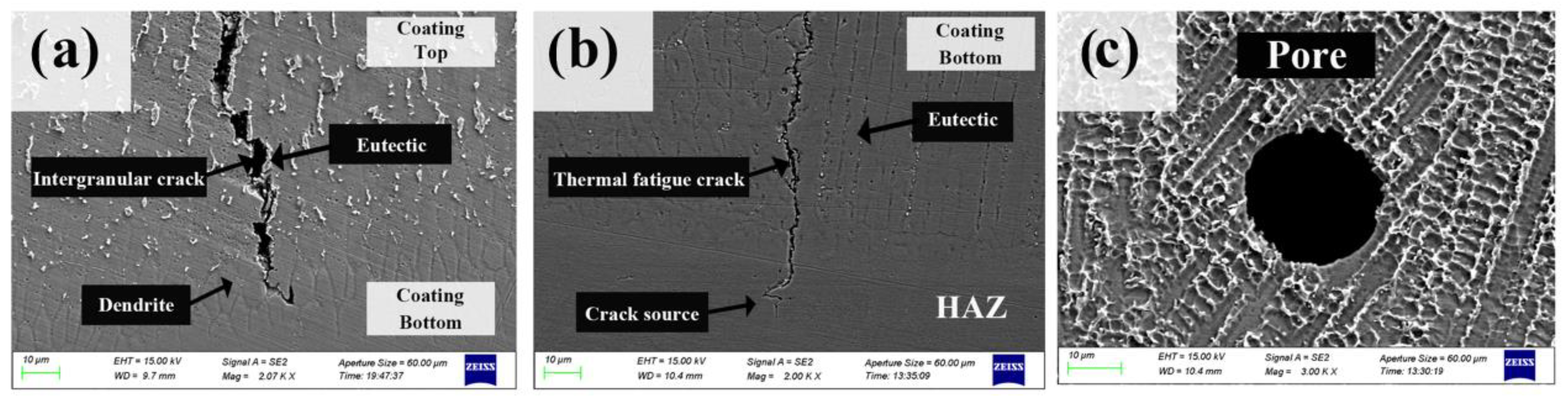
3.3. Defects
3.4. High-Temperature Oxidation Resistance
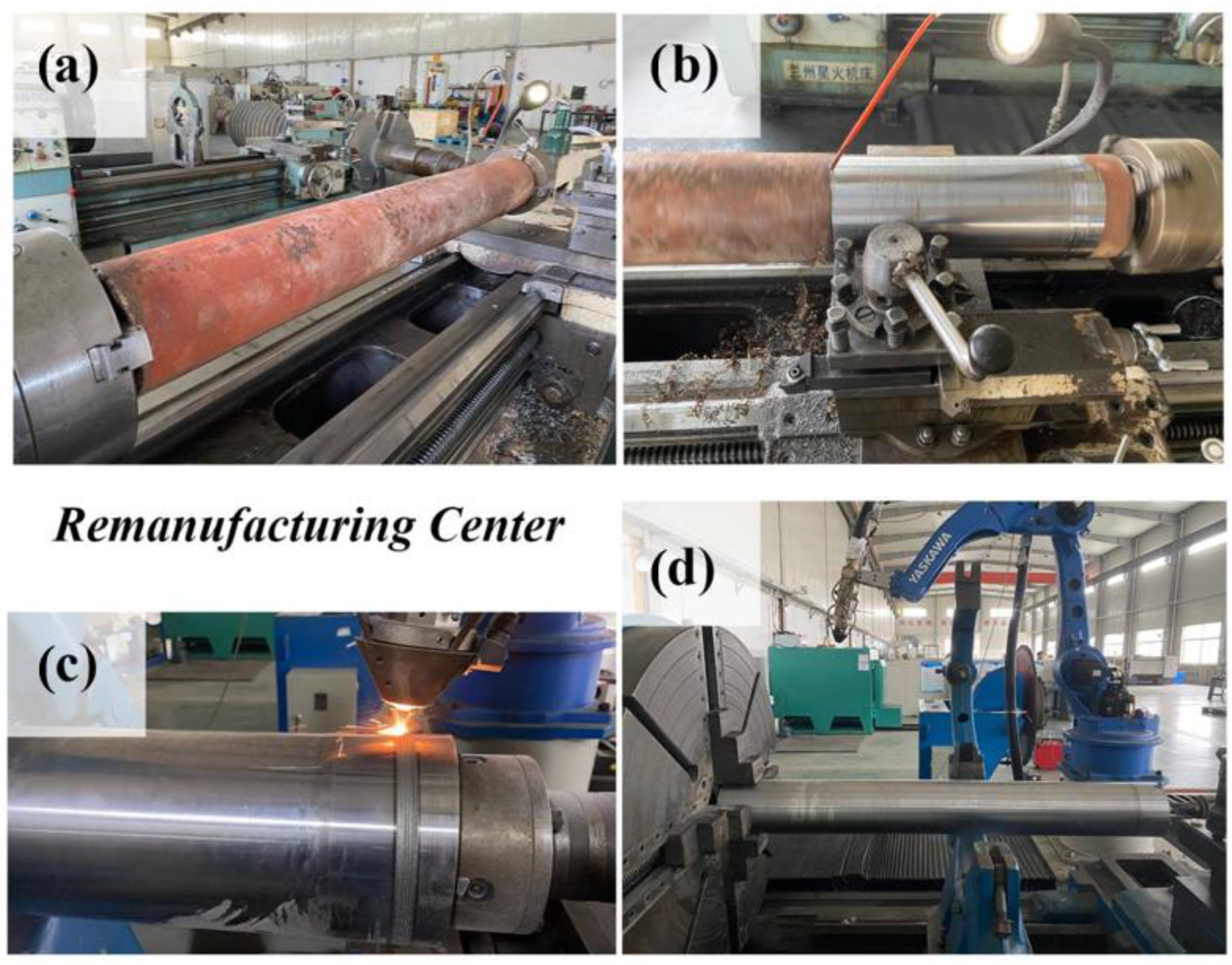
3.5. Engineering Application
4. Conclusions
- When the scanning speed increased from 5 mm/s to 15 mm/s, the top region’s dendrites refined, and eutectic quantity increased. When the laser power increased from 1600 W to 2400 W, the dendrite in the top region coarsened, and the eutectic quantity decreased. Lower power and faster scanning speed improve the cooling rate, resulting in increased precipitation of eutectic elements. The change of laser process parameters affected the number of strengthening phases precipitated in the parent phase and subsequently changed the hardness of the coating.
- When the scanning speed was increased from 5 mm/s to 15 mm/s, the average hardness of HAZ was increased by about 26 %. Under the condition of laser heating and rapid cooling, martensite with high hardness was generated in the HAZ region. Nevertheless, the brittleness of martensite also increased the crack sensitivity of HAZ, and the thermal fatigue cracks in HAZ initiated under thermal cyclic loading. The HAZ cracks along the thickness of the coating, resulting in coating failure.
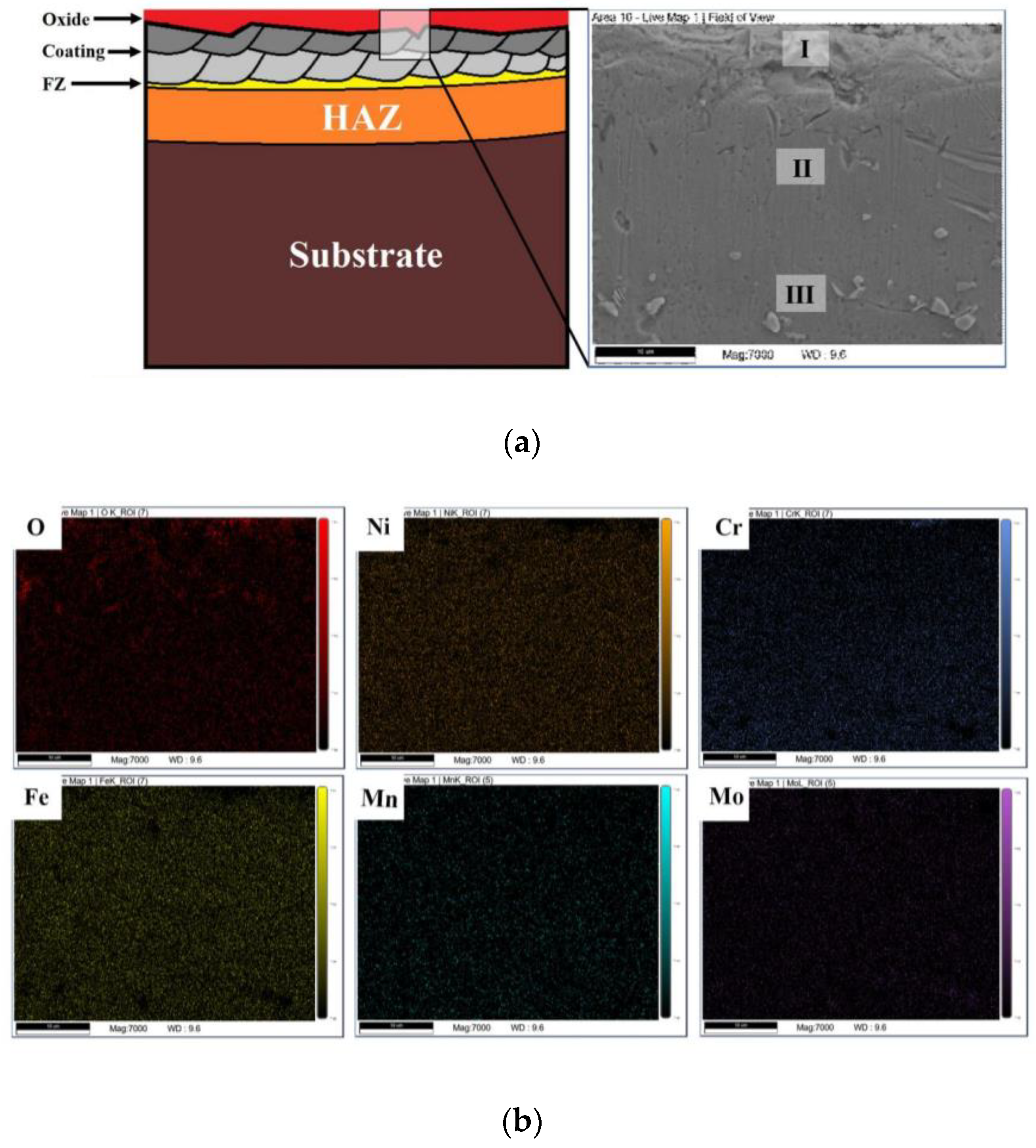
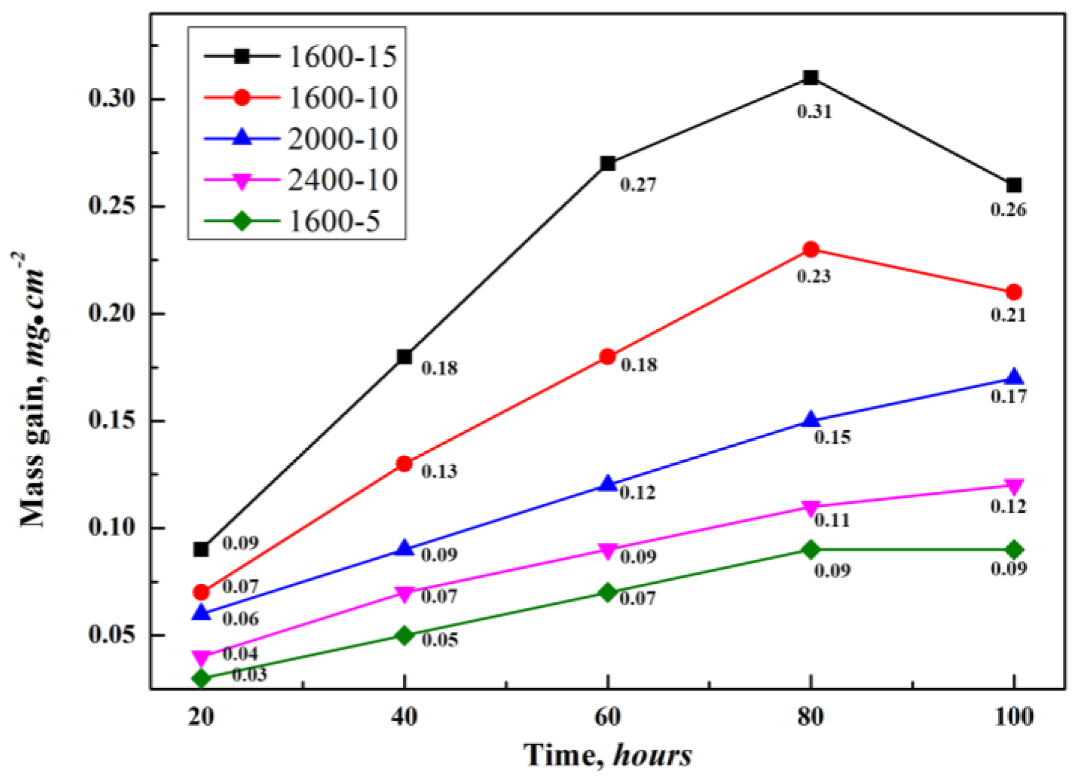
- When the scanning speed was increased from 5 mm/s to 15 mm/s, the mass gain was increased by about 188%. When the laser power increased from 1600 W to 2400 W, the mass gain decreased by about 43%. The formation of oxide was closely related to the distribution of the Ni3Nb phase in the top region of the coating. The less eutectic precipitation, the better the high-temperature oxidation resistance of IN718 coating. The scanning speed had a more significant impact on the high-temperature oxidation resistance.
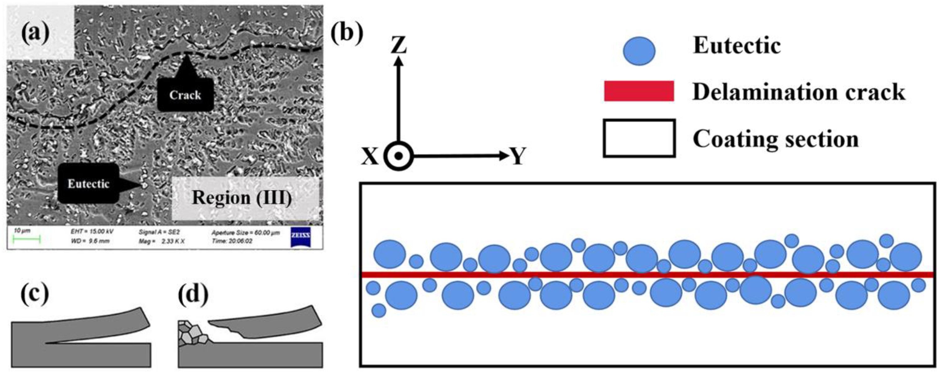
- The high-temperature behavior of the IN718 coating can be divided into surface oxidation, intergranular corrosion, and material shedding. The combined action of delamination cracks and intergranular corrosion led to material shedding. Crack extension increased the surface contact area in the oxidation environment, which negatively affected the high-temperature oxidation resistance of IN718 coating.
Author Contributions
Funding
Institutional Review Board Statement
Informed Consent Statement
Data Availability Statement
Conflicts of Interest
References
- Chen, S.; Ma, Y. The Research of the Chemistry Composition of High Temperature Oxidization under Loads for the Cr5Mo Alloy. Mater. Sci. Forum 2011, 694, 729–732. [Google Scholar] [CrossRef]
- Chen, S. Study on the Micro-Structure of High Temperature Oxide Scales Applied Loads on Cr5Mo Alloy. Adv. Mater. Res. 2011, 197–198, 1086–1091. [Google Scholar] [CrossRef]
- Muth, W.A. Effect of Pressure on the Flammable Limits of Some Hydrocarbon-Air Mixtures. Ph.D. Thesis, Iowa State University of Science and Technology, Ames, IA, USA, 1963. [Google Scholar] [CrossRef]
- Yuan, W.; Li, R.; Chen, Z.; Gu, J.; Tian, Y. A comparative study on microstructure and properties of traditional laser cladding and high-speed laser cladding of Ni45 alloy coatings. Surf. Coat. Technol. 2018, 405, 126582. [Google Scholar] [CrossRef]
- Song, M.; Wu, L.; Liu, J.; Hu, Y. Effects of laser cladding on crack resistance improvement for aluminum alloy used in aircraft skin. Opt. Laser Technol. 2021, 133, 106531. [Google Scholar] [CrossRef]
- Tang, Z.; Liu, W.; Zhu, L.; Liu, Z. Investigation on coaxial visual characteristics of molten pool in laser-based directed energy deposition of AISI 316L steel. J. Mater. Process. Technol. 2021, 290, 116996. [Google Scholar] [CrossRef]
- Mazzarisi, M.; Campanelli, S.L.; Angelastro, A.; Palano, F.; Dassisti, M. In situ monitoring of direct laser metal deposition of a nickel-based superalloy using infrared thermography. Int. J. Adv. Manuf. Technol. 2020, 112, 157–173. [Google Scholar] [CrossRef]
- Lv, H.; Li, Z.; Li, X.; Yang, K.; Li, F.; Xie, H. Investigation on the Microporosity Formation of IN718 Alloy during Laser Cladding Based on Cellular Automaton. Materials 2021, 14, 837. [Google Scholar] [CrossRef]
- Rezaei, A.; Kermanpur, A.; Rezaeian, A.; Badrossamay, M.; Foroozmehr, E.; Sadeghi, F.; Han, J.; Park, T.M. Contribution of hot isostatic pressing on densification, microstructure evolution, and mechanical anisotropy of additively manufactured IN718 Ni-based superalloy. Mater. Sci. Eng. A 2021, 823, 141721. [Google Scholar] [CrossRef]
- Xie, H.; Yang, K.; Li, F.; Sun, G.; Yu, Z. Investigation on the Laves phase formation during laser cladding of IN718 alloy by GA-FE. J. Manuf. Process. 2020, 52, 132–144. [Google Scholar] [CrossRef]
- Zhang, Y.; Yang, L.; Dai, J.; Liu, J.; Zhang, W.; Chen, H.; Wang, Z.; Shi, K. Microstructure and mechanical properties of pulsed laser cladded IN718 alloy coating. Surf. Eng. 2016, 34, 259–266. [Google Scholar] [CrossRef]
- Jia, Q.; Gu, D. Selective laser melting additive manufactured Inconel 718 superalloy parts: High-temperature oxidation property and its mechanisms. Opt. Laser Technol. 2014, 62, 161–171. [Google Scholar] [CrossRef]
- Jian, Y.; Shi, Y.; Liu, J. Effect of laser pretreatment and laser cladding on the interface bond strength and surface properties of vermicular graphite. J. Mater. 2022, 57, 6929–6942. [Google Scholar] [CrossRef]
- Mazzarisi, M.; Angelastro, A.; Latte, M.; Colucci, T.; Palano, F.; Campanelli, S.L. Thermal monitoring of laser metal deposition strategies using infrared thermography. J. Manuf. Process. 2023, 85, 594–611. [Google Scholar] [CrossRef]
- Korkmaz, M.E.; Gupta, M.K.; Waqar, S.; Kuntoglu, M.; Krolczyk, G.M.; Maruda, R.W.; Pimenov, D.Y. A short review on thermal treatments of Titanium & Nickel based alloys processed by selective laser melting. J. Mater. Res. Technol. 2022, 16, 1090–1101. [Google Scholar] [CrossRef]
- Sanviemvongsak, T.; Monceau, D.; Macquaire, B. High temperature oxidation of IN 718 manufactured by laser beam melting and electron beam melting: Effect of surface topography. Corros. Sci. 2018, 141, 127–145. [Google Scholar] [CrossRef] [Green Version]
- Thouless, M.D. Cracking and delamination of coatings. J. Vac. Sci. Technol. A 1991, 9, 2510–2515. [Google Scholar] [CrossRef]
- Fang, Y.; Chen, N.; Du, G.; Zhang, M.; Zhao, X.; Cheng, H.; Wu, J. High-temperature oxidation resistance, mechanical and wear resistance properties of Ti(C,N)-based cermets with Al0.3CoCrFeNi high-entropy alloy as a metal binder. J. Alloys Compd. 2020, 815, 152486. [Google Scholar] [CrossRef]
- Sumit, S.K.; Biswas, K.; Nath, A.K.; Manna, I.; Majumdar, J.D. Microstructural Change during Laser Welding of Inconel 718. Optik 2020, 218, 165029. [Google Scholar] [CrossRef]
- Kang, X.; Dong, S.; Wang, H.; Yan, S.; Liu, X.; Xu, B. Effect of laser power on gradient microstructure of low-alloy steel built by laser melting deposition. Mater. Lett. 2020, 262, 127073. [Google Scholar] [CrossRef]
- Liu, J.; Song, Y.; Chen, C.; Wang, X.; Li, H.; Zhou, C.; Wang, J.; Guo, K.; Sun, J. Effect of scanning speed on the microstructure and mechanical behavior of 316L stainless steel fabricated by selective laser melting. Mater. Des. 2020, 186, 108355. [Google Scholar] [CrossRef]
- Du, L.; Gu, D.; Dai, D.; Shi, Q.; Ma, C.; Xia, M. Relation of thermal behavior and microstructure evolution during multi-track laser melting deposition of Ni-based material. Opt. Laser Technol. 2018, 108, 207–217. [Google Scholar] [CrossRef]
- Savitha, U.; Gokhale, H.; Reddy, G.J.; Venkataramana, A.; Gokhale, A.A.; Sundararaman, M. Effect of Process Parameters on Porosity in Laser Deposited IN625 Alloy. Trans. Indian Inst. Met. 2012, 65, 765–770. [Google Scholar] [CrossRef]
- Mankins, W.L.; Hosier, J.C.; Bassford, T.H. Microstructure and phase stability of INCONEL alloy 617. Metall. Mater. Trans. B 1974, 5, 2579–2590. [Google Scholar] [CrossRef]
- Adomako, N.K.; Park, H.J.; Cha, S.C.; Lee, M.; Kim, J.H. Microstructure evolution and mechanical properties of the dissimilar joint between IN718 and STS304. Mater. Sci. Eng. A 2021, 799, 140262. [Google Scholar] [CrossRef]
- Abdollah-Zadeh, A.; Salemi, A.; Assadi, H. Mechanical behavior of CrMo steel with tempered martensite and ferrite-bainite-martensite microstructure. Metall. Mater. Trans. A 2008, 483–484, 325–328. [Google Scholar] [CrossRef]
- Lingenfelter, A. Welding of Inconel alloy 718: A historical overview. TMS 1989, 718, 673–683. Available online: https://www.tms.org/Superalloys/10.7449/1989/Superalloys_1989_673_683.pdf (accessed on 1 January 2021).
- Cao, J.; Zhang, J.; Hua, Y.; Rong, Z.; Chen, R.; Ye, Y. High temperature oxidation behavior of Ni-based superalloy GH586 in air. Rare Met. 2017, 36, 878–885. [Google Scholar] [CrossRef]
- Cao, J.; Zhang, J.; Hua, Y.; Chen, R.; Ye, Y. Improving the high temperature oxidation resistance of Ni-based superalloy GH202 induced by laser shock processing. J. Mater. Process. Technol. 2017, 243, 31–39. [Google Scholar] [CrossRef]
- Wu, L.; Xiao, Y.; Xia, X.; Qian, J.; He, Y. High temperature oxidation resistance of porous Ni-Cr-Fe materials. Int. J. Mater. Res. 2020, 111, 126582. [Google Scholar] [CrossRef]
- Leo Prakash, D.G.; Walsh, M.J.; Maclachlan, D.; Korsunsky, A.M. Crack growth micro-mechanisms in the IN718 alloy under the combined influence of fatigue, creep and oxidation. Int. J. Fatigue 2009, 31, 1966–1977. [Google Scholar] [CrossRef]
- Xing, L.; Gu, C.; Lv, Z.; Bao, Y. High-temperature internal oxidation behavior of surface cracks in low alloy steel bloom. Corros. Sci. 2022, 197, 110076. [Google Scholar] [CrossRef]
- Cao, L.; Du, C.; Shao, S.; Xie, G. Remaining life prediction of ethylene cracking tubes under carburizing and creep joint action. ASME PVP 2015, 56994, V06AT06A040. [Google Scholar] [CrossRef]
- Zheng, Y.; Yang, S.; Ling, X. Creep life prediction of small punch creep testing specimens for service-exposed Cr5Mo using the theta-projection method. Eng. Fail. Anal. 2017, 72, 58–66. [Google Scholar] [CrossRef]
- Xu, Z.; Cao, L.; Zhu, Q.; Guo, C.; Li, X.; Hu, X.; Yu, Z. Creep property of Inconel 718 superalloy produced by selective laser melting compared to forging. Mater. Sci. Eng. A 2020, 794, 139947. [Google Scholar] [CrossRef]


| Substrate | Cr | Mo | Mn | C | Si | Nb | Ni | Fe |
|---|---|---|---|---|---|---|---|---|
| Cr5Mo | 5.02 | 0.54 | 0.35 | 0.10 | 0.54 | 0.02 | - | Bal. |
| IN718 | 21.0 | 3.3 | 0.35 | 0.08 | 0.35 | 5.50 | Bal. | 14.50 |
| Experimental Group | Laser Power (W) | Scanning Speed (mm/s) |
|---|---|---|
| 1600-5 | 1600 | 5 |
| 1600-10 | 1600 | 10 |
| 1600-15 | 1600 | 15 |
| 2000-10 | 2000 | 10 |
| 2400-10 | 2400 | 10 |
| - | 1600-5 | 1600-10 | 1600-15 | 2000-10 | 2400-10 |
|---|---|---|---|---|---|
| Coating | 300.8 | 344.3 | 345.6 | 279.8 | 306.4 |
| 249.8 | 276.5 | 367.9 | 238.7 | 251.5 | |
| FZ | 218.3 | 225.7 | 304.2 | 186.5 | 162.4 |
| HAZ | 284.9 | 324.1 | 400.9 | 335.4 | 325.2 |
| 307.3 | 340.8 | 370.8 | 441.4 | 333.8 | |
| 269.5 | 281.3 | 314.2 | 291.8 | 283.8 | |
| Substrate | Average 252.9 | ||||
| Marked Locations | O | Mo | Cr | Mn | Fe | Ni | Nb |
|---|---|---|---|---|---|---|---|
| I | 6.37 | 8.13 | 7.49 | 0.11 | 28.01 | 48.59 | 1.30 |
| II | 0.86 | 4.71 | 18.83 | 0.37 | 27.50 | 45.51 | 2.22 |
| III | 1.01 | 25.13 | 2.38 | 0.26 | 5.06 | 45.34 | 20.83 |
Disclaimer/Publisher’s Note: The statements, opinions and data contained in all publications are solely those of the individual author(s) and contributor(s) and not of MDPI and/or the editor(s). MDPI and/or the editor(s) disclaim responsibility for any injury to people or property resulting from any ideas, methods, instructions or products referred to in the content. |
© 2023 by the authors. Licensee MDPI, Basel, Switzerland. This article is an open access article distributed under the terms and conditions of the Creative Commons Attribution (CC BY) license (https://creativecommons.org/licenses/by/4.0/).
Share and Cite
Xu, Z.; Wang, F.; Peng, S.; Liu, W.; Guo, J. Effects of Process Parameters on Microstructure and High-Temperature Oxidation Resistance of Laser-Clad IN718 Coating on Cr5Mo Steel. Coatings 2023, 13, 197. https://doi.org/10.3390/coatings13010197
Xu Z, Wang F, Peng S, Liu W, Guo J. Effects of Process Parameters on Microstructure and High-Temperature Oxidation Resistance of Laser-Clad IN718 Coating on Cr5Mo Steel. Coatings. 2023; 13(1):197. https://doi.org/10.3390/coatings13010197
Chicago/Turabian StyleXu, Zelin, Fengtao Wang, Shitong Peng, Weiwei Liu, and Jianan Guo. 2023. "Effects of Process Parameters on Microstructure and High-Temperature Oxidation Resistance of Laser-Clad IN718 Coating on Cr5Mo Steel" Coatings 13, no. 1: 197. https://doi.org/10.3390/coatings13010197