Article

High-Temperature Steam Oxidation of Accident-Tolerant Cr/Mo-Coated Zr Alloy at 1200–1400 °C

School of Nuclear Science & Engineering, Tomsk Polytechnic University, 30 Lenina Av., 634050 Tomsk, Russia
*
Author to whom correspondence should be addressed.
Coatings 2023, 13(1), 191; https://doi.org/10.3390/coatings13010191
Submission received: 26 December 2022 / Revised: 10 January 2023 / Accepted: 13 January 2023 / Published: 15 January 2023
(This article belongs to the Special Issue Advanced Coatings for Accident Tolerant Fuel Claddings)

Abstract

:
The oxidation resistance under LOCA conditions of bilayer Cr/Mo coating deposited on Zr-1Nb zirconium alloy was investigated in this paper. The bilayer Cr (8 μm)/Mo (3 μm) coatings were deposited by magnetron sputtering. Then, oxidation resistance under high-temperature oxidation at 1200–1400 °C in a water steam was studied. The use of a Mo sublayer resulted in limiting Cr-Zr interdiffusion under high-temperature oxidation. It was shown that the Mo barrier sublayer (~3 μm) can provide the protective behavior of the Cr/Mo-coated Zr at 1330 °C in a water steam for at least 720 s. The weight gain of the bilayer Cr/Mo samples was comparable with the monolayer Cr samples after oxidation at 1400 °C. In addition, the analysis of the Cr/Mo-coated Zr alloy oxidation behavior at 1400 °C was carried out.

1. Introduction

The accident at the Fukushima nuclear power plant in 2011 showed that nuclear reactors need new cladding materials because zirconium alloy claddings can lose their integrity under high-temperature oxidation in a water steam, resulting in hydrogen generation [1,2,3]. Accident-tolerant fuel (ATF) claddings should provide additional time to eliminate the consequences of design-based accidents such as loss of coolant accident (LOCA) [4]. In addition, it should retain performance characteristics under the normal operating conditions of the nuclear reactor [5].
Currently, the search of protective coatings and its deposition on zirconium fuel claddings is a promising approach to improving resistance to high-temperature oxidation [5,6,7,8,9]. This strategy is short-term because it does not require significant changes in the design of the nuclear reactor and the structural elements of its active zone [10,11]. Another strategy is to replace zirconium alloys with other materials, such as SiCf/SiC [12], FeCrAl [13], molybdenum alloys [14], etc. However, this long-term strategy is more expensive and requires a complete rejection of the currently using Zr alloys, which have excellent characteristics under normal operating conditions (360 °C, 18.6 MPa) [15,16].
Chromium has attracted the attention of scientists as a potential material to protect zirconium alloys due to high melting point, suitable thermal expansion coefficient, and excellent oxidation resistance at high temperatures [17,18,19,20,21]. The oxidation resistance is attributed to the formation of a stable and dense Cr2O3 layer on the chromium surface in a water vapor [22,23]. However, despite all advantages of chromium, it has a problem of Cr-Zr interdiffusion followed by the Cr2Zr intermetallic compound at temperatures higher than those of α→β phase transition of Zr alloy [24]. This compound, with lattice parameters much larger than Cr and Zr, begins to expand the entire system with the formation of additional grain boundaries [25]. Thus, there are additional diffusion paths for oxygen into the zirconium alloy with the further formation of the ZrO2 phase, which has even larger lattice parameters [25]. As a result, oxidation of the zirconium alloy is significantly accelerated, resulting in the cracking and degradation of the protective coating [26]. Therefore, different barrier sublayers are considered to suppress the Cr-Zr interdiffusion [27,28,29,30,31].
Some studies using a barrier sublayers between the Cr coating and the Zr alloy have already been performed. A bilayer ZrO2/Cr coating was deposited on the zirconium alloy by cathodic-arc deposition and plasma electrolytic oxidation in [29]. It was found that the ZrO2 sublayer can suppresses oxygen diffusion up to 1100 °C. However, the oxidation behavior of the protective coating at higher temperatures has not been established. In addition, an approach using ZrO2-based multilayer barrier coatings has been proposed [28]. It was found that steam oxidation at higher temperatures (1200–1400 °C) accelerated the mutual diffusion of Cr-Zr due to the formation of cavities at the interface of the ZrO2/Cr multilayers. CrN/Cr multilayers were proposed as barrier coatings [27,30]. High-temperature steam oxidation showed the formation of the Cr2Zr at higher temperatures than the single-layer Cr coating. However, these coatings were effective for a short period of time (~2 min at temperatures of 1330–1365 °C). In addition, trilayer Cr-CrN/TiSiN-Cr coatings to prevent Cr-Zr interdiffusion were studied in [31]. Steam oxidation at 1200 °C for 25 min showed formation pores at the oxide/nitride coating interface, followed by the formation of bulges. Several high-melted metals, such as Ta, Mo, and Re, are suggested to apply as a barrier sublayers for Cr-coated Zr alloys [26]. Molybdenum has been used to effectively suppress the Cr-Zr interdiffusion layer formation [26,32,33]. Mo satisfies a number of parameters that are important for intermediate sublayer, such as a good adhesion strength and similar thermal expansion coefficients to chromium coating and zirconium alloy [26,32]. In [34], the application of an intermediate layer of Mo between the zirconium alloy and CrAl demonstrated a prolonged resistance to high-temperature oxidation up to 1300 °C. However, applying such a thick (23–25 μm) coating will increase the thermal neutron capture cross-section [10], which is not acceptable in terms of a neutron economy. Coatings with a Mo sublayer with a lower thickness should be investigated under high-temperature oxidation. In our previous work [35], it was shown that the bilayer Cr (8 µm)/Mo (3 µm) coating limited Cr-Zr interdiffusion and demonstrated well resistance to oxidation in air at 1100 °C for 60 min. However, the resistance of this type of coating to oxidation in a water steam at the higher temperature (>1100 °C) remains unclear. It is important to determine the oxidation resistance of the bilayer coating at a temperature higher than the melting point of the Cr-Zr eutectic phase (1332 °C)
The aim of this work is to investigate the oxidation resistance and diffusion behavior under LOCA conditions of a bilayer Cr/Mo coating deposited on Zr-1Nb zirconium alloy by magnetron sputtering.

2. Materials and Methods

2.1. Sample Preparation

Flat (15 × 15 × 2 mm3) sheets and tubes (outer diameter—9.1 mm, inner—7.9 mm, length—10 mm) of zirconium Zr-1Nb alloy (0.9–1.1 wt.% Nb, 0.06–0.1 wt.% O, Zr balanced) were used as substrates. Special holes (Ø2 mm) were drilled into the flat samples to fix them under oxidation test before the deposition of coatings. The samples were ground and polished by silicon carbide (SiC) paper (P600→P1200→P2500→P4000) using the MP-1B machine (TIME Group Inc., Beijing, China). The samples were then rinsed in an ultrasonic bath with acetone for 15 min. Before coating deposition, the samples were also boiled and dried in isopropyl alcohol.

2.2. Coating Deposition

The deposition of coatings was carried out by the magnetron sputtering method using a non-commercial ion-plasma installation developed in TPU (Tomsk, Russia) [36]. Before deposition, the substrates were subjected to ion bombardment by argon ions for 20 min using a Hall drift electron ion source. The ion treatment was performed at the following parameters: ion current, I = 38 mA, discharge voltage, U = 2.5 kV, and argon pressure, p = 0.12 Pa. The residual pressure in the chamber was 10−3 Pa.
A bilayer Cr (8 μm)/Mo (3 μm) coating was deposited in this work. The Cr (99.95% purity) coating was deposited by multicathode magnetron sputtering with a direct current (DC) power supply. Cr coating deposition modes have been presented in previous papers [18,27]. The molybdenum sublayer was deposited by DC magnetron sputtering. Mo targets (Ø90 mm) had a purity of 99.95%. The temperature of the samples was measured using an Optris CT laser 3MH1CF4 infrared pyrometer (Optris GmbH, Berlin, Germany) during the coating deposition. The deposition parameters are presented in Table 1.
Single-layer Cr-coated samples were additionally deposited to compare the oxidation behavior of samples [27].

2.3. Oxidation Tests under LOCA Conditions

High-temperature oxidation tests were carried out in steam at 1200 °C, in accordance with the U.S. NRC guideline by a LOCA345 test facility (SC VNIINM, Moscow, Russia). The samples were kept in the cold zone at 300 °C for 300 s; it was then moved to the high-temperature zone of the furnace and heated to 1200 °C with a heating rate of 20 °C/s. The flow rate of water steam was equal to ~4.0 mg/cm2. The temperature of the samples was maintained at 1200 ± 3 °C. After the oxidation, the samples were immediately quenched in water. The test duration was 1000 and 2000 s.
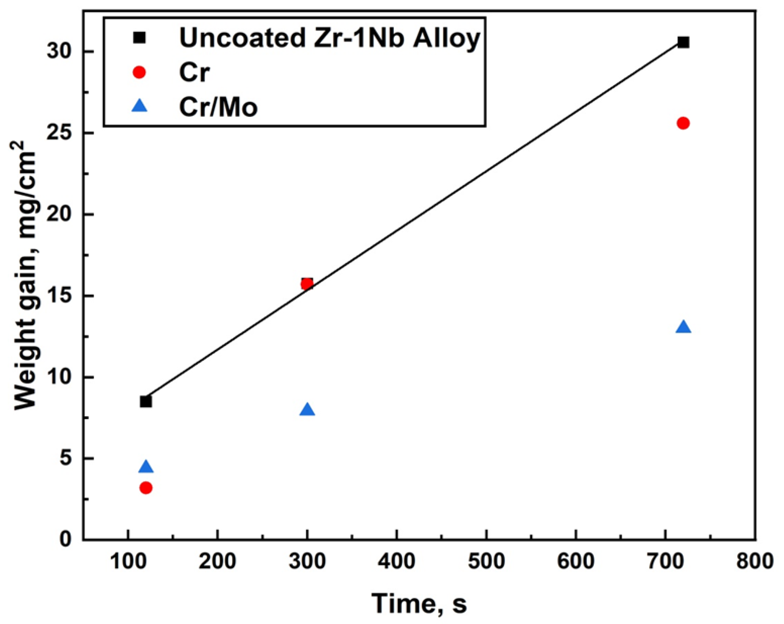
The steam oxidation test at the temperature of 1330 and 1400 °C was performed using a GASPAR test facility in JSC LUCH (JSC LUCH, Podolsk, Russia), consisting of a ceramic tube (Ø28 × 2 mm2) installed in a furnace with a graphite heater. The mass flow of water steam and heating rates were equal to 40 mg/s and 33 °C/s, respectively. The oxidation times at 1330 °C and 1400 °C were 120–720 s and 120 s. After oxidation, the samples were moved to the cold zone of the chamber and cooling to 900 °C in a steam with a rate of 20 °C/s. The samples were then immediately quenched in water.
The weight gain of the samples was measured by an analytical balance CP 124S (Sartorius, Göttingen, Germany) with an accuracy of 10−4 g. The specific weight gain was calculated, taking into account the uncoated part of the sample (uncoated area at the fixing place of the holder and substrate) according to the procedure described in [37].

2.4. Characterization

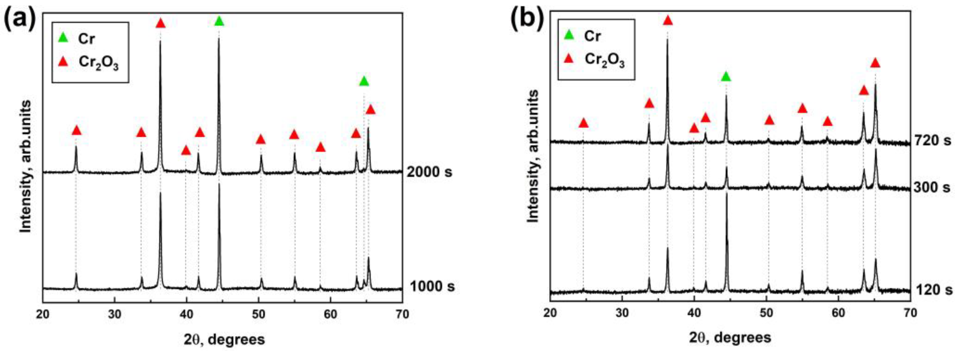
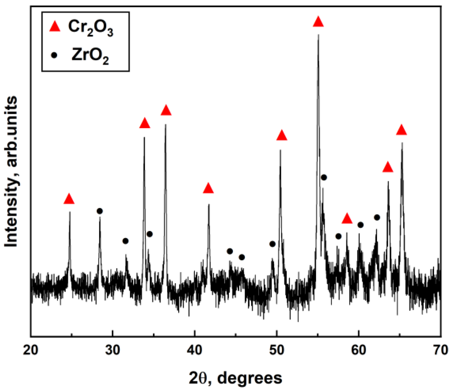
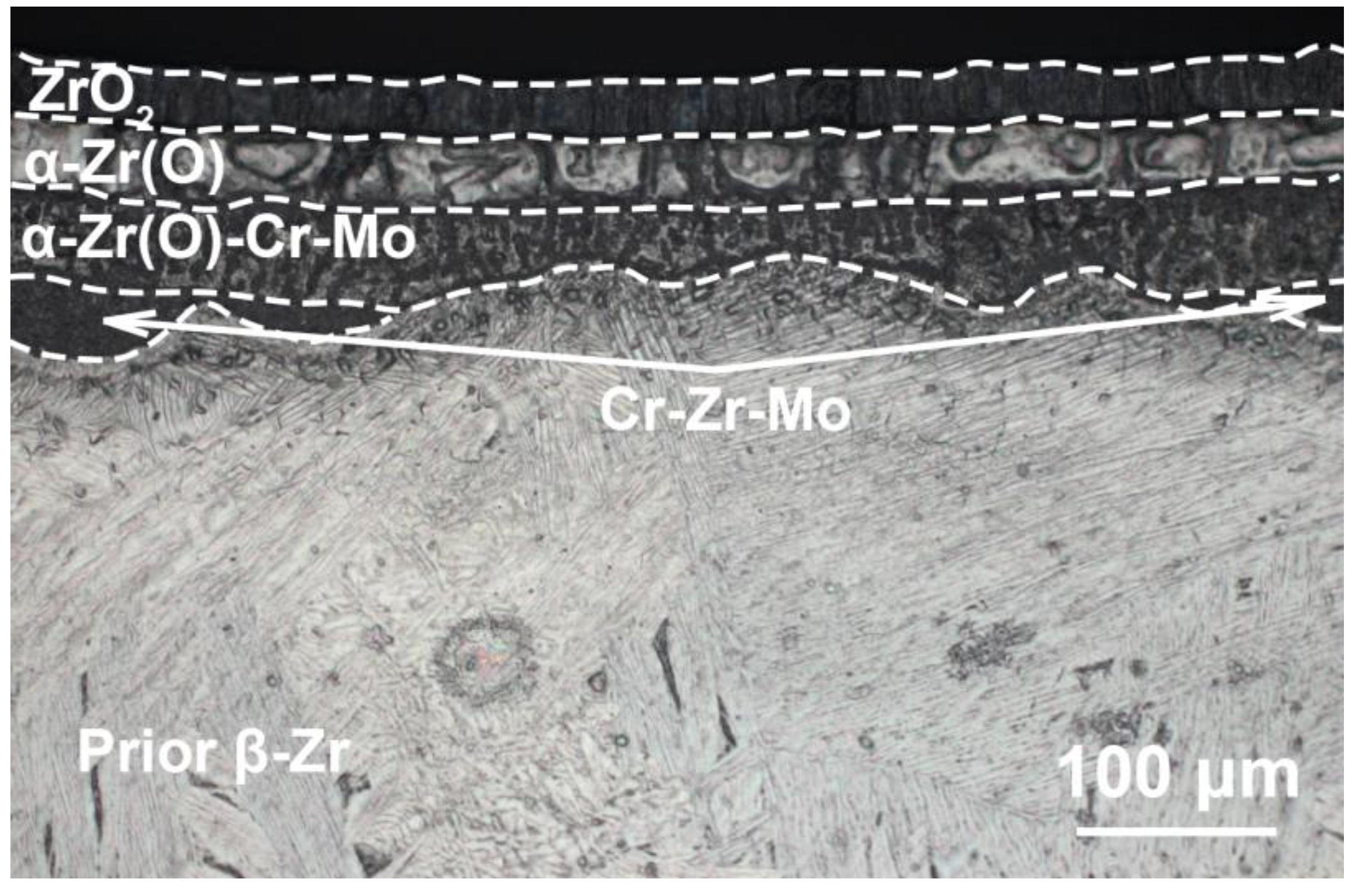
Microstructure and elemental composition of the samples after oxidation were analyzed by scanning electron microscopy (SEM) using MIRA3 (Brno, Czech Republic) with energy dispersive spectroscopy (EDS) attachment Ultim Max 40 (Oxford Instruments, High Wycombe, UK). In addition, optical microscopy (OM) (AXIOVERT 200MAT, Zeiss, Jena, Germany) was used to analyze the cross-section microstructure of the samples after oxidation. The phase composition of samples was studied by X-ray diffraction using an XRD-7000S diffractometer (Shimadzu, Kyoto, Japan) in a Bragg–Brentano configuration with CuKα-radiation (wave length λ =1.54 Å) at 40 kV and 30 mA. The PDF4+ 2021 database and SIeve software were used to determine the phase composition of the samples.

3. Results and Discussion

3.1. Weight Gain Measurements

The samples were photographed after high-temperature oxidation in steam to analyze their outer view. Table 2 shows the outer view and weight gain of the samples after oxidation at 1200 °C.
All coated samples lost their metallic color and had a dark green color of Cr2O3 scale after oxidation at 1200 °C. The uncoated samples had a dark gray color, which corresponds to the ZrO2 scale (Table 2). The coated samples showed significantly less weight gain after oxidation at 1200 °C compared to the uncoated Zr-1Nb alloy (Table 2). Cr- and Cr/Mo-coated samples had a comparable weight gain up to 2000 s. Both coatings retained their protective properties, and the weight gain of samples was an order of magnitude lower compared to the uncoated ones. Moreover, the Cr/Mo coating showed the lowest weight gain of 1.51 mg/cm2 and 2.28 mg/cm2 after oxidation for 1000 and 2000 s, respectively.
The second oxidation test was performed at the temperature of a possible Cr-Zr eutectic reaction (∼1305−1325 °C). No significant changes in the outer view of the uncoated and coated samples were observed after oxidation in a steam for 120 s (Table 3). All samples had a dark gray color, indicating the formation of oxides, which is similar to the oxidation at 1200 °C. After 720 s oxidation, the uncoated and Cr/Mo-coated samples also had no significant change in outer view. It should be noted that white areas appearing on the uncoated sample indicated accelerated local oxidation due to cracking or disruption of the outer oxide scale. The outer view of the Cr-coated sample shows typical Post-Quenching (PQ) appearance after 300 s steam oxidation at temperatures above the Zr-Cr eutectic reaction. The Cr-coated sample had a “crocodile skin” morphology with some continuous blisters, which was earlier observed by Brachet et al. [25].
After 120 s of oxidation at 1330 °C, the coated samples show 2–3 times less weight gain compared to uncoated Zr alloy (8.5 mg/cm2) (Figure 1). However, the weight gain of the Cr-coated sample becomes comparable to the uncoated sample (~16 mg/cm2) after 300 s. This indicates a dramatic loss of protective properties of the coating as contrasted with Cr/Mo coating, which has a weight gain of an order of magnitude less. The Cr/Mo-coated Zr alloy has the lowest weight gain through the whole oxidation period and demonstrates good oxidation resistance up to 720 s.
The final oxidation test was performed at a supercritical (beyond eutectic) temperature of 1400 °C for 120 s. The outer view of the uncoated Zr alloy has a pronounced black color in contrast to the coated samples, with a green bulging oxide film (Table 4). In addition, the Cr/Mo-coated sample has bubbles on the surface, and metallic color areas are also observed. The metallic areas are formed due to partial delamination of the surface oxide scale under quenching. The uncoated, Cr-, and Cr/Mo-coated samples demonstrate similar oxidation weight gains, indicating the weak protective properties of the coatings. The formation of a rough morphology on the surface of the coated samples is explained by the “capillary” effect, which will be described in more detail in Section 3.4.

3.2. Phase Composition after Oxidation

Figure 2a shows the diffraction patterns of Cr-coated Zr alloy after HT oxidation at 1200 °C for 1000 and 2000 s. According to XRD, it is observed that the oxidation leads to the formation of a rhombohedral Cr2O3 oxide phase. The reflections of a body-centered cubic α-Cr phase are also found and correspond to residual Cr coating. The molybdenum phase of the sublayer was not observed due to insufficient penetration of X-rays through the protective coating (coating thickness, ~8.5 μm). The intensities of the oxide phase become higher when the oxidation time increases from 1000 to 2000 s, indicating a higher content (thickness) of the Cr2O3 outer oxide layer. A similar trend of the Cr2O3 growth with increasing oxidation time was observed at 1330 °C (Figure 2b). Furthermore, the residual Cr is still observed, even after oxidation for 720 s. In our previous work [35], as well as in several papers by other authors [38,39], the Cr3Mo phase was found at the sublayer/protective coating interface during HT oxidation. The absence of this phase in the diffraction patterns can be related to insufficient oxidation time at both 1200 °C and 1330 °C. Apparently, the Cr3Mo forms in local areas at the sublayer/protective coating interface under the specified conditions of oxidation.
Figure 3 shows the diffraction pattern of the Cr/Mo-coated sample after HT oxidation at a supercritical temperature of 1400 °C. Analysis of the diffraction pattern shows that Cr2O3 and ZrO2 with a monoclinic crystal lattice are formed after oxidation. The formation of the zirconium oxide phase is associated with the loss of integrity of the protective coating during oxidation at 1400 °C as a result of the eutectic formation. The XRD data agree well with the sample outer view after oxidation (Table 4), which shows the protective coating delamination.

3.3. Optical Microscopy after Oxidation

Figure 4, Figure 5 and Figure 6 show the optical cross-section images of the oxidized Cr/Mo-coated Zr alloy samples at different temperatures.
Oxidation at 1200 °C. A four-layer structure was observed in OM images of the oxidized samples. The outer layer is represented by dense and relatively uniform Cr2O3 oxide (Figure 4). Underneath the oxide layer, residual Cr/Mo coating and Mo-Zr interdiffusion layers were found. The inner layer is characterized by a prior β-Zr phase. A slight increase in the oxide layer thickness is observed with increasing oxidation time from 1000 to 2000 s. However, it can be seen that the Cr/Mo coating thickness decreased significantly due to the Mo diffusion into the Zr alloy [40]. As a result, the thickness of the Mo-Zr interdiffusion layer increased from about 12 to 20 μm (Figure 4). It should be assumed that Mo2Zr is formed as a result of Mo-Zr interdiffusion at high temperatures, which was observed in our previous study at 1100 °C air oxidation [35] and in several other works [33,40].
Oxidation at 1330 °C. The microstructure of the samples after oxidation at 1330 °C for 120 s (Figure 5a) is the same as after oxidation tests at 1200 °C (Figure 4). However, an interdiffusion Cr-Mo layer was observed between the residual Cr/Mo coating and the interdiffusion Mo-Zr layer after oxidation for 300 s (Figure 5b). The thickness of this layer increases with increasing oxidation time to 720 s. It is clearly seen that the thickness of the outer Cr2O3 layer increases from 4.5 μm to 6 μm with oxidation time. Moreover, the residual Cr/Mo coating is also significantly consumed due to the Cr-Mo and Mo-Zr interdiffusion. The thickness of Mo-Zr layer increases from about 26 to 42 μm as the oxidation time increases from 120 to 720 s, respectively.
Oxidation at 1400 °C. A significant change in the microstructure is observed after oxidation at 1400 °C (Figure 6). The oxide layers consisted of outer columnar ZrO2, and oxygen-stabilized α-Zr(O) phases were formed. The formation of such layers was also observed during oxidation of the uncoated and Cr-coated Zr alloy in steam at 1400 °C for 120 s in [27]. For the Cr/Mo-coated Zr alloy, the thickness of the ZrO2 oxide layer was ~2.5 and 2 times lower compared to the uncoated and Cr-coated samples. This fact indicates a short-term effect of the barrier Mo sublayer at 1400 °C. Previously, it was shown that a green Cr2O3 oxide was observed on the surface of the Cr/Mo-coated Zr-1Nb (Table 4), but this layer is not present on the OM image. This is because the Cr2O3 oxide layer has a small thickness, which is not resolved in the optical image. Based on the elemental composition, the sample microstructure is also represented by an α-Zr(O) layer enriched with Cr and Mo and an Cr-Zr interdiffusion layer. The formation of Cr-enriched areas is explained by the rapid Cr diffusion into the Zr alloy due to oxidation of Cr2Zr to Cr and ZrO2 [25].

3.4. Scanning Electron Microscopy after Oxidation

Figure 7, Figure 8 and Figure 9 show cross-section SEM images of the Cr/Mo-coated zirconium Zr-1Nb alloy samples after steam oxidation at 1200–1400 °C.
Oxidation at 1200 °C. Figure 7 shows that six-layer structures were formed after oxidation at 1200 °C for 1000 s: 1—outer Cr2O3 oxide layer (∼5 μm); 2—residual Cr layer (∼7 μm); 3—Cr-Mo interdiffusion layer (∼1.3 μm); 4—Mo residual layer (∼1.3 μm); 5—Mo-Zr interdiffusion layer (<0.5 μm); 6—prior β-Zr layer. The elemental composition in the selected points (in Figure 7) is presented in Table 5. The increase in oxidation time to 2000 s results in thickening of the outer Cr2O3 layer (to ∼6 μm), and the Cr-Mo interdiffusion layer also increased to ∼1.7 μm. The thickness of the residual Cr/Cr-Mo layer is reduced to ∼6 μm. It was shown in the previous study [41] that the residual Cr layer was also ∼5.5 μm after the oxidation at 1200 °C of the single-layer Cr coating with comparable thickness (8 μm), but after a much shorter period (10 min). Moreover, the oxidation of the single-layer Cr coating results in the Cr-Zr interdiffusion with the formation of Cr2Zr precipitations, which accelerates the Zr alloy oxidation [25]. Thus, it can be concluded that the Mo barrier sublayer between the Zr alloy and the protective Cr coating can significantly suppress the Cr-Zr interdiffusion at 1200 °C for such oxidation period (up to 2000 s).
Oxidation at 1330 °C. Figure 8 shows the cross-section microstructure and EDS elemental distribution maps of the Cr-coated Zr alloy samples after steam oxidation at 1330 °C for 120–720 s. The data show that the microstructure of the coated samples after oxidation at 1330 °C is similar to that observed after oxidation at 1200 °C. The faster oxidation and interdiffusion kinetics at 1330 °C results in rapid growth of the Cr2O3 oxide layer (from 5 to 9.5 μm), Cr-Mo (from 0.8 to 1.5 μm), and Mo-Zr (from 0.5 to 2.7 μm) layers with an increasing oxidation time from 120 to 720 s, respectively. At the same time, the residual Cr thickness decreased from 7.3 to 5.3 μm in these experiments. It should be noted that LOCA oxidation for 720 s leads to the formation of a Cr-Mo-Zr diffusion layer of ∼3 μm thickness, which is clearly visible on the EDS maps (Figure 8). This layer is stable and does not form the eutectic layer due to higher melting temperature compared to the Cr-Zr eutectic layer observed at 1305–1325 °C [25]. Therefore, the 3 µm-thick Mo barrier layer can provide the protective behavior of the Cr/Mo-coated Zr alloy at 1330 °C in a water steam for at least 720 s.
Oxidation at 1400 °C. LOCA oxidation at the supercritical temperature of 1400 °C for 120 s leads to a significant change in the microstructure and elemental composition of the samples (Figure 9). The cross-section SEM image shows the formation of a six-layer structure: 1—thin outer Cr2O3 layer, 2—ZrO2 oxide layer (~33 μm); 3—α-Zr(O) layer (~38 μm); 4—α-Zr(O) layer enriched with Cr and Mo (~41 μm); 5—eutectic Cr-Zr-Mo layer (~36 μm); 6—prior β-Zr layer. According to EDS analysis (Table 6), layer 4 consists of two α-Zr(O) phases: Cr-enriched (dark areas) and Cr-depleted (light areas). It should be noted that the molybdenum content in both areas is the same (up to 2 at.%). Layer 5 is represented by a typical dendritic structure, which is formed as a result of solidification of the Cr-Zr eutectic zone during quenching after LOCA oxidation, as well as the prior β-Zr(Mo) phase enriched in Mo and oxygen [25]. Elemental analysis shows a low Mo content (up to 5 at.%) in the interdiffusion layer (layer 5). It is well known that molybdenum has good solubility in zirconium (up to 20 at.%) [42]. It is most likely that molybdenum is in the crystal lattice of the prior β-Zr phase enriched with Cr and formed a solid solution.
The SEM image also shows blisters at the ZrO2/α-Zr(O) interface. The formation of these blisters is most probably associated with a displacement of the eutectic Cr-Zr-Mo layer on the surface region due to the “capillary” effect of the Cr-Zr liquid phase and then local swelling caused by solid-to-liquid volume changes [28]. Thus, the use of a Mo barrier sublayer (3 µm thick) between the protective Cr coating (8.5 µm-thick) and the Zr alloy during LOCA oxidation in a water steam at 1400 °C cannot effectively suppress the Cr-Zr interdiffusion for 120 s. Molybdenum actively diffuses into the zirconium alloy at the specified temperature, resulting in loss of its barrier properties. The obtained data suggest that the suppression effect of Cr-Zr interdiffusion during LOCA oxidation at 1400 °C cannot be performed by a 3 µm-thick Mo barrier layer, even for a short-term oxidation period.

3.5. Cr/Mo-Coated Zr-1Nb Alloy Oxidation Analysis

A schematic diagram of the oxidation process at 1400 °C for the Cr/Mo-coated Zr-1Nb alloy is presented in Figure 10. At the initial stage, the protective Cr coating is rapidly oxidized to form the Cr2O3 outer layer (Figure 10b). The residual Cr and Mo as well as Mo and Zr can be mutually diffused between each other to form corresponding Cr-Mo and Mo-Zr interdiffusion layers (as observed in the case of oxidation at lower (1200–1330 °C) temperatures). The voids at the Cr2O3/Cr, Cr-Mo/Mo, and Mo/Mo-Zr interfaces can be produced by the Kirkendall mechanism due to the difference between the diffusion coefficients of different atoms, which causes the formation of vacancies and voids [28]. The Kirkendall voids can grow in size due to their coalescence.
At the next stage of oxidation, Cr and Mo are completely consumed by the formation of the Cr-Mo-Zr and Mo-Zr interdiffusion layers (Figure 10c). As the temperature of the sample was higher than the melting point of the Cr-Zr eutectic phase, a liquid Cr-Zr(Mo) layer formed in the interdiffusion zone. Such a liquid phase caused a “capillary” effect and local swelling associated with the solid-to-liquid volume change, resulting in displacement of the eutectic Cr-Zr(Mo) layer to the surface region [25]. The above-mentioned reasons lead to accelerated oxygen diffusion because the outer protective oxide scale can lose its integrity. The oxidation of the Cr-Zr(Mo) liquid layer results in the formation of ZrO2 and metallic Cr and Mo due to the lower Gibbs free energy of ZrO2 compared to the Cr2O3 and MoO3 oxides [43]. The chromium produced during the reaction and molybdenum will diffuse into the Zr alloy, resulting in the formation of the Cr-Mo enriched layer in the prior β-Zr phase (Figure 10d). Inward oxygen diffusion results in the growth of the ZrO2 layer beneath the Cr2O3 outer layer and stabilization of the Cr(Mo)-enriched Zr in the α-phase by oxygen underneath the ZrO2 layer. The latter causes the shift of the Cr-Mo-enriched layer in more depth of the Zr alloy.
The formation of blisters at the ZrO2/α-Zr(O) interface can be explained as follows. It is assumed that blisters are formed during oxidation, otherwise the continuous growth of the α-Zr(O) layer around the blisters would not be observed. It is known that Cr-Zr melt density at 1400 °C is ~5.9 g/cm3 [44]. The density difference between ZrO2 (5.68 g/cm3) and Cr-Zr(Mo) leads to a pressure gradient; as a result, the melt can move to defect regions (especially voids) near the ZrO2/α-Zr(O) interface. This is confirmed by the fact that the outer layer of the blister has a composition similar to the liquid eutectic layer. The microstructural analysis showed a round shape of the blisters after cooling, which indicates that they filled with gas. The interaction of the Cr-Zr(Mo) melt with inward oxygen flux can lead to the generation of volatile oxide phases. For example, Tedmon found that CrO3 oxide evaporation is slight at 1000 °C, but becomes severe with the temperature increase [45,46]. Furthermore, the presence of molybdenum can contribute to the higher generation of the gaseous phase because Mo-O compounds evaporate at relatively low temperatures [47]. Thus, it was found that the oxidation results in the formation of a liquid eutectic phase with the release of gaseous products, which leads to the formation of blisters, mainly at the oxide interface. However, the mechanisms of blister formation require further detailed study.
Up to a now, only a few candidate materials have been studied as a barrier layer for Cr-coated Zr alloys [8,27,28,29,30,31,32,35,48,49]. The present study indicates that the fast molybdenum diffusion in the alloy can deteriorate the barrier properties of the Mo sublayer at high temperatures (>1200 °C), while the 3 µm-thick Mo layer can limit Cr-Zr interdiffusion in the case of oxidation at lower temperatures (1100 °C), as shown in several studies [32,35]. Applying barrier layers based on oxides or nitrides (e.g., CrN, Cr2N, ZrO2 [8,29,30]) shows that a thick ceramic layers cannot be resistant to high-temperature ramps, whereas metal layers are more resistant under the same high-temperature conditions [48]. Coatings with ZrO2/Cr or CrN/Cr multilayers [27,28,31,49] can act as inner sources for Cr-Zr interdiffusion or limit a Cr-Zr interdiffusion only up to a certain extent. Therefore, it is most likely that other metal layers (Ta, Re [26]) can have better barrier properties for preventing Cr-Zr interdiffusion than that of molybdenum.

4. Conclusions

The presented article demonstrates the behavior of zirconium (Zr-1Nb) alloy with a protective chromium coating (∼8.5 μm) and a molybdenum barrier sublayer (∼3 μm) under high-temperature oxidation in a water stream in the temperature range of 1200–1400 °C. Analysis of the oxidation of Cr/Mo-coated Zr alloy and interdiffusion in the Cr-Mo-Zr system based on corrosion weight gain, OM, SEM, EDS, and XRD revealed the following conclusions.
  • The thicknesses of the residual Cr layers of Cr/Mo-coated Zr alloy samples were 6.0 and 5.3 μm after oxidation at 1200 °C for 2000 s and 1330 °C for 720 s, respectively. The higher thicknesses of the residual Cr layers compared to the Cr-coated Zr samples indicates that the application of a molybdenum barrier sublayer (3 μm-thick) can be used to limit Cr-Zr interdiffusion during LOCA oxidation at 1200 and 1330 °C.
  • LOCA oxidation at 1200–1330 °C leads to the formation of Cr-Mo and Mo-Cr interdiffusion layers at the “protective coating-barrier sublayer” and “barrier sublayer-zirconium alloy” interfaces, respectively. An increase in the oxidation time from 120 to 720 s at 1330 °C is accompanied by an increase in the Mo-Zr interdiffusion layer from 26 to 42 μm. The Cr-Mo-Zr interdiffusion layer formation with a ∼3 µm thickness is also observed.
  • The weight gain of the Cr/Mo-coated Zr alloy sample is comparable with the Cr-coated Zr samples after LOCA oxidation at 1400 °C for 120 s. For ZrO2, α-Zr(O), and α-Zr(O) enriched with Cr and Mo, a Cr-Zr(Mo) interdiffusion layer with the characteristic dendritic structure of the eutectic phase is formed as a result of 1400 °C oxidation. The formation of these phases, weight gain, and significant Mo diffusion indicate the loss of sublayer barrier properties.

Author Contributions

Conceptualization, M.S.; methodology, A.A.; validation, E.K.; formal analysis, M.S., E.K. and D.S.; investigation, M.S., A.A., K.G. and D.S.; writing—original draft preparation M.S. and A.A.; writing—review and editing, M.S., E.K., A.A. and D.S.; visualization, A.A.; supervision, M.S.; project administration, M.S.; funding acquisition, M.S. All authors have read and agreed to the published version of the manuscript.

Funding

The research was funded by the Russian Science Foundation (Grant No. 21-79-00175).

Institutional Review Board Statement

Not applicable.

Informed Consent Statement

Not applicable.

Data Availability Statement

Not applicable.

Acknowledgments

The authors acknowledge the TPU Development program.

Conflicts of Interest

The authors declare no conflict of interest.

References

  1. Su, H.; Wu, X.; Wu, L.; Zhao, S.; Zhong, Y.; Ning, Z.; Liu, N.; Yang, J. Effect of Nb Content on Microstructure, Mechanical Property, High-Temperature Corrosion and Oxidation Resistance of CrNb Coatings for Accident Tolerant Fuel Cladding. Int. J. Refract. Met. Hard Mater. 2023, 110, 106010. [Google Scholar] [CrossRef]
  2. Terrani, K.A. Accident Tolerant Fuel Cladding Development: Promise, Status, and Challenges. J. Nucl. Mater. 2018, 501, 13–30. [Google Scholar] [CrossRef]
  3. Qiu, B.; Wang, J.; Deng, Y.; Wang, M.; Wu, Y.; Qiu, S.Z. A Review on Thermohydraulic and Mechanical-Physical Properties of SiC, FeCrAl and Ti3SiC2 for ATF Cladding. Nucl. Eng. Technol. 2020, 52, 1–13. [Google Scholar] [CrossRef]
  4. Ott, L.J.; Robb, K.R.; Wang, D. Preliminary Assessment of Accident-Tolerant Fuels on LWR Performance during Normal Operation and under DB and BDB Accident Conditions. J. Nucl. Mater. 2014, 448, 520–533. [Google Scholar] [CrossRef]
  5. Wagih, M.; Spencer, B.; Hales, J.; Shirvan, K. Fuel Performance of Chromium-Coated Zirconium Alloy and Silicon Carbide Accident Tolerant Fuel Claddings. Ann. Nucl. Energy 2018, 120, 304–318. [Google Scholar] [CrossRef]
  6. Tang, C.; Große, M.; Ulrich, S.; Klimenkov, M.; Jäntsch, U.; Seifert, H.J.; Stüber, M.; Steinbrück, M. High-Temperature Oxidation and Hydrothermal Corrosion of Textured Cr2AlC-Based Coatings on Zirconium Alloy Fuel Cladding. Surf. Coat. Technol. 2021, 419, 127263. [Google Scholar] [CrossRef]
  7. Chen, H.; Wang, X.; Zhang, R. Application and Development Progress of Cr-Based Surface Coatings in Nuclear Fuel Element: I. Selection, Preparation, and Characteristics of Coating Materials. Coatings 2020, 10, 808. [Google Scholar] [CrossRef]
  8. Wang, X.; Liao, Y.; Xu, C.; Guan, H.; Zhu, M.; Gao, C.; Jin, X.; Pang, P.; Du, J.; Liao, B.; et al. Steam Oxidation Behavior of ZrO2/Cr-Coated Pure Zirconium Prepared by Plasma Electrolytic Oxidation Followed by Filtered Cathodic Vacuum Arc Deposition. J. Alloys Compd. 2021, 883, 160798. [Google Scholar] [CrossRef]
  9. Dogan, H.; Findik, F.; Oztarhan, A. Comparative study of wear mechanism of surface treated AISI 316L stainless steel. Ind. Lubr. Tribol. 2003, 55, 76–83. [Google Scholar] [CrossRef]
  10. Younker, I.; Fratoni, M. Neutronic Evaluation of Coating and Cladding Materials for Accident Tolerant Fuels. Prog. Nucl. Energy 2016, 88, 10–18. [Google Scholar] [CrossRef]
  11. Rebak, R.B. Accident-Tolerant Materials for Light Water Reactor Fuels; Elsevier: Amsterdam, The Netherlands, 2020. [Google Scholar]
  12. Kim, D.; Lee, H.-G.; Park, J.Y.; Kim, W.-J. Fabrication and Measurement of Hoop Strength of SiC Triplex Tube for Nuclear Fuel Cladding Applications. J. Nucl. Mater. 2015, 458, 29–36. [Google Scholar] [CrossRef]
  13. Yamamoto, Y.; Pint, B.A.; Terrani, K.A.; Field, K.G.; Yang, Y.; Snead, L.L. Development and Property Evaluation of Nuclear Grade Wrought FeCrAl Fuel Cladding for Light Water Reactors. J. Nucl. Mater. 2015, 467, 703–716. [Google Scholar] [CrossRef] [Green Version]
  14. Cheng, B.; Chou, P.; Kim, Y.-J. Evaluations of Mo-Alloy for Light Water Reactor Fuel Cladding to Enhance Accident Tolerance. EPJ Nucl. Sci. Technol. 2016, 2, 5. [Google Scholar] [CrossRef] [Green Version]
  15. Cheng, B.; Kim, Y.-J.; Chou, P. Improving Accident Tolerance of Nuclear Fuel with Coated Mo-Alloy Cladding. Nucl. Eng. Technol. 2016, 48, 16–25. [Google Scholar] [CrossRef] [Green Version]
  16. Bragg-Sitton, S. Development of Advanced Accident-Tolerant Fuels for Commercial LWRs. Nucl. News 2014, 57, 83. [Google Scholar]
  17. Hu, X.; Dong, C.; Wang, Q.; Chen, B.; Yang, H.; Wei, T.; Zhang, R.; Gu, W.; Chen, D. High-Temperature Oxidation of Thick Cr Coating Prepared by Arc Deposition for Accident Tolerant Fuel Claddings. J. Nucl. Mater. 2019, 519, 145–156. [Google Scholar] [CrossRef]
  18. Sidelev, D.V.; Poltronieri, C.; Bestetti, M.; Krinitcyn, M.G.; Grudinin, V.A.; Kashkarov, E.B. A Comparative Study on High-Temperature Air Oxidation of Cr-Coated E110 Zirconium Alloy Deposited by Magnetron Sputtering and Electroplating. Surf. Coat. Technol. 2022, 433, 128134. [Google Scholar] [CrossRef]
  19. Yeom, H.; Maier, B.; Johnson, G.; Dabney, T.; Lenling, M.; Sridharan, K. High Temperature Oxidation and Microstructural Evolution of Cold Spray Chromium Coatings on Zircaloy-4 in Steam Environments. J. Nucl. Mater. 2019, 526, 151737. [Google Scholar] [CrossRef]
  20. Yang, J.; Steinbrück, M.; Tang, C.; Große, M.; Liu, J.; Zhang, J.; Yun, D.; Wang, S. Review on Chromium Coated Zirconium Alloy Accident Tolerant Fuel Cladding. J. Alloys Compd. 2022, 895, 162450. [Google Scholar] [CrossRef]
  21. Duan, Z.; Yang, H.; Satoh, Y.; Murakami, K.; Kano, S.; Zhao, Z.; Shen, J.; Abe, H. Current Status of Materials Development of Nuclear Fuel Cladding Tubes for Light Water Reactors. Nucl. Eng. Des. 2017, 316, 131–150. [Google Scholar] [CrossRef]
  22. Park, D.J.; Kim, H.G.; Jung, Y., II; Park, J.H.; Yang, J.H.; Koo, Y.H. Behavior of an Improved Zr Fuel Cladding with Oxidation Resistant Coating under Loss-of-Coolant Accident Conditions. J. Nucl. Mater. 2016, 482, 75–82. [Google Scholar] [CrossRef]
  23. Brachet, J.-C.; Idarraga-Trujillo, I.; Le Flem, M.; Le Saux, M.; Vandenberghe, V.; Urvoy, S.; Rouesne, E.; Guilbert, T.; Toffolon-Masclet, C.; Tupin, M.; et al. Early Studies on Cr-Coated Zircaloy-4 as Enhanced Accident Tolerant Nuclear Fuel Claddings for Light Water Reactors. J. Nucl. Mater. 2019, 517, 268–285. [Google Scholar] [CrossRef]
  24. Yang, J.; Stegmaier, U.; Tang, C.; Steinbrück, M.; Große, M.; Wang, S.; Seifert, H.J. High Temperature Cr-Zr Interaction of Two Types of Cr-Coated Zr Alloys in Inert Gas Environment. J. Nucl. Mater. 2021, 547, 152806. [Google Scholar] [CrossRef]
  25. Brachet, J.-C.; Rouesne, E.; Ribis, J.; Guilbert, T.; Urvoy, S.; Nony, G.; Toffolon-Masclet, C.; Le Saux, M.; Chaabane, N.; Palancher, H.; et al. High Temperature Steam Oxidation of Chromium-Coated Zirconium-Based Alloys: Kinetics and Process. Corros. Sci. 2020, 167, 108537. [Google Scholar] [CrossRef]
  26. Kashkarov, E.; Afornu, B.; Sidelev, D.; Krinitcyn, M.; Gouws, V.; Lider, A. Recent Advances in Protective Coatings for Accident Tolerant Zr-Based Fuel Claddings. Coatings 2021, 11, 557. [Google Scholar] [CrossRef]
  27. Sidelev, D.V.; Ruchkin, S.E.; Syrtanov, M.S.; Kashkarov, E.B.; Shelepov, I.A.; Malgin, A.G.; Polunin, K.K.; Stoykov, K.V.; Mokrushin, A.A. Protective Cr Coatings with CrN/Cr Multilayers for Zirconium Fuel Claddings. Surf. Coat. Technol. 2022, 433, 128131. [Google Scholar] [CrossRef]
  28. Sidelev, D.V.; Ruchkin, S.E.; Shelepov, I.A.; Saburov, N.S.; Malgin, A.G.; Polunin, K.K.; Stoykov, K.V.; Mokrushin, A.A. Protective Cr Coatings with ZrO2/Cr Multilayers for Zirconium Fuel Claddings. Coatings 2022, 12, 1409. [Google Scholar] [CrossRef]
  29. Wang, X.; Guan, H.; Liao, Y.; Zhu, M.; Xu, C.; Jin, X.; Liao, B.; Xue, W.; Zhang, Y.; Bai, G.; et al. Enhancement of High Temperature Steam Oxidation Resistance of Zr–1Nb Alloy with ZrO2/Cr Bilayer Coating. Corros. Sci. 2021, 187, 109494. [Google Scholar] [CrossRef]
  30. Krejč’i, J.; Ševeček, M.; Kabátová, J.; Manoch, F.; Koč’i, J.; Cvrček, L.; Málek, J.; Krum, S.; Šutta, P.; Bubl’iková, P.; et al. Experimental Behavior of Chromium-Based Coatings. In Proceedings of the TopFuel 2018, Prague, Czech Republic, 30 September–4 October 2018. [Google Scholar]
  31. Liu, J.; Hao, Z.; Cui, Z.; Ma, D.; Lu, J.; Cui, Y.; Li, C.; Liu, W.; Xie, S.; Huang, P.; et al. Investigation of the Oxidation Mechanisms of Superlattice Cr-CrN/TiSiN-Cr Multilayer Coatings on Zircaloy Substrates under High-Temperature Steam Atmospheres. Corros. Sci. 2021, 192, 109782. [Google Scholar] [CrossRef]
  32. Michau, A.; Ougier, M.; Maskrot, H.; Brachet, J.C.; Guilbert, T.; Palancher, H.; Bischoff, J.; Pouillier, E. Interlayers for Cr-Coated Nuclear Fuel Claddings. In Proceedings of the NuMat2020-The Nuclear Materials Conference, Ghent, Belgium, 26–30 October 2020. [Google Scholar] [CrossRef]
  33. Yeom, H.; Maier, B.; Johnson, G.; Dabney, T.; Walters, J.; Sridharan, K. Development of Cold Spray Process for Oxidation-Resistant FeCrAl and Mo Diffusion Barrier Coatings on Optimized ZIRLOTM. J. Nucl. Mater. 2018, 507, 306–315. [Google Scholar] [CrossRef]
  34. Zhu, C.; Li, P.; Chen, C.; Tian, J.; Zeng, S.; Meng, Y.; Shen, H.; Han, X.; Zhang, H. Microstructure Evolution and Oxidation Behavior of Bi-Layer CrAl-Mo Coated Zircaloy-4 in Steam at 1200 °C and 1300 °C. Corros. Sci. 2022, 208, 110632. [Google Scholar] [CrossRef]
  35. Syrtanov, M.S.; Kashkarov, E.B.; Abdulmenova, A.V.; Sidelev, D. V High-Temperature Oxidation of Zr1Nb Zirconium Alloy with Protective Cr/Mo Coating. Surf. Coat. Technol. 2022, 439, 128459. [Google Scholar] [CrossRef]
  36. Sidelev, D.V.; Kashkarov, E.B.; Syrtanov, M.S.; Krivobokov, V.P. Nickel-Chromium (Ni–Cr) Coatings Deposited by Magnetron Sputtering for Accident Tolerant Nuclear Fuel Claddings. Surf. Coat. Technol. 2019, 369, 69–78. [Google Scholar] [CrossRef]
  37. Kashkarov, E.B.; Sidelev, D.V.; Rombaeva, M.; Syrtanov, M.S.; Bleykher, G.A. Chromium Coatings Deposited by Cooled and Hot Target Magnetron Sputtering for Accident Tolerant Nuclear Fuel Claddings. Surf. Coat. Technol. 2020, 389, 125618. [Google Scholar] [CrossRef]
  38. Peng, J. Cr-Mo Binary Phase Diagram Evaluation. Available online: https://materials.springer.com/msi/docs/sm_msi_r_20_012108_01 (accessed on 24 November 2022).
  39. Song, H.; Lei, J.; Xie, J.; Wu, S.; Wang, L.; Shou, W. Laser Melting Deposition of K403 Superalloy: The Influence of Processing Parameters on the Microstructure and Wear Performance. J. Alloys Compd. 2019, 805, 551–564. [Google Scholar] [CrossRef]
  40. y Puente, A.P.; Dickson, J.; Keiser, D.D., Jr.; Sohn, Y.H. Investigation of Interdiffusion Behavior in the Mo–Zr Binary System via Diffusion Couple Studies. Int. J. Refract. Met. Hard Mater. 2014, 43, 317–321. [Google Scholar] [CrossRef]
  41. Kashkarov, E.B.; Sidelev, D.V.; Syrtanov, M.S.; Tang, C.; Steinbrück, M. Oxidation Kinetics of Cr-Coated Zirconium Alloy: Effect of Coating Thickness and Microstructure. Corros. Sci. 2020, 175, 108883. [Google Scholar] [CrossRef]
  42. Zinkevich, M.; Mattern, N. Thermodynamic Assessment of the Mo-Zr System. J. Phase Equilibria 2002, 23, 156–162. [Google Scholar] [CrossRef]
  43. Farle, A.-S.; Kwakernaak, C.; van der Zwaag, S.; Sloof, W.G. A Conceptual Study into the Potential of Mn+1AXn-Phase Ceramics for Self-Healing of Crack Damage. J. Eur. Ceram. Soc. 2015, 35, 37–45. [Google Scholar] [CrossRef]
  44. Ohishi, Y.; Kondo, T.; Ishikawa, T.; Okada, J.T.; Watanabe, Y.; Muta, H.; Kurosaki, K.; Yamanaka, S. Physical Properties of Molten Core Materials: Zr-Ni and Zr-Cr Alloys Measured by Electrostatic Levitation. J. Nucl. Mater. 2017, 485, 129–136. [Google Scholar] [CrossRef]
  45. Tedmon, C.S. The Effect of Oxide Volatilization on the Oxidation Kinetics of Cr and Fe-Cr Alloys. J. Electrochem. Soc. 1966, 113, 766. [Google Scholar] [CrossRef]
  46. Graham, H.C.; Davis, H.H. Oxidation/Vaporization Kinetics of Cr2O3. J. Am. Ceram. Soc. 1971, 54, 89–93. [Google Scholar] [CrossRef]
  47. Zhang, C.; Gao, M.C.; Yang, Y.; Zhang, F. Thermodynamic Modeling and First-Principles Calculations of the Mo–O System. Calphad 2014, 45, 178–187. [Google Scholar] [CrossRef]
  48. Xiao, W.; Chen, H.; Liu, X.; Tang, D.; Deng, H.; Zou, S.; Ren, Y.; Zhou, X.; Lei, M. Thermal Shock Resistance of TiN-, Cr-, and TiN/Cr-Coated Zirconium Alloy. J. Nucl. Mater. 2019, 526, 151777. [Google Scholar] [CrossRef]
  49. Chen, Q.; Yang, H.; Wu, L.; Wu, X.; Zhu, C.; He, L.; Liu, N.; Yang, Y.; Liao, J.; Yang, J. Effect of the Ar/N2 Flow Ratio on the Microstructure, Mechanical Properties, and High-Temperature Steam Oxidation Behavior of Cr/CrxN Coatings for Accident-Tolerant Fuel Coatings. Corros. Sci. 2021, 192, 109833. [Google Scholar] [CrossRef]
Figure 1. Weight gains of the uncoated, Cr-, and Cr/Mo-coated Zr alloy after oxidation at 1330 °C as a function of oxidation time.
Coatings 13 00191 g001
Figure 2. Diffraction patterns of the Cr/Mo-coated samples after oxidation at 1200 °C (a) and 1330°C (b).
Coatings 13 00191 g002
Figure 3. Diffraction pattern of the Cr/Mo-coated sample after oxidation at 1400 °C during 120 s.
Coatings 13 00191 g003
Figure 4. Cross-section optical micrographs of the Cr/Mo-coated Zr alloy samples after oxidation at 1200 °C for 1000 s (a) and 2000 s (b).
Coatings 13 00191 g004
Figure 5. Cross-section optical micrographs of Cr/Mo-coated Zr alloy samples after oxidation at 1330 °C for 120 s (a), 300 s (b), and 720 s (c).
Coatings 13 00191 g005
Figure 6. Cross-section optical micrograph of the Cr/Mo-coated Zr alloy sample after oxidation at 1400 °C for 120 s.
Coatings 13 00191 g006
Figure 7. Cross-section SEM images of the Cr/Mo-coated Zr alloy samples after steam oxidation at 1200 °C for 1000 s (a) and 2000 s (b).
Coatings 13 00191 g007
Figure 8. SEM images and EDS elemental distribution maps of the Cr/Mo-coated Zr alloy samples after LOCA oxidation at 1330 °C for 120 (a), 300 (b), and 720 s (c).
Coatings 13 00191 g008
Figure 9. Cross-section SEM image of the Cr/Mo-coated Zr alloy sample after LOCA oxidation at 1400 °C for 120 s.
Coatings 13 00191 g009
Figure 10. Schematic diagram of the oxidation process for the Cr/Mo-coated Zr-1Nb alloy at 1400 °C: initial state (a); stage I (b); stage II (c); stage III (d).
Coatings 13 00191 g010
Table 1. Deposition parameters of Cr and Mo layers.
LayerQ, W/cm2Ub, Vjs, mA/ cm2t, hTmax, °Ch, µm
Cr39−50652.53208
Mo39−50551.63203
Note: Q—discharge power density; Ub—substrate bias potential; js—current density on a substrate; t—deposition time; Tmax—maximum deposition temperature; h—coating thickness.
Table 2. The outer view and weight gain (in mg/cm2) of the samples after LOCA oxidation at 1200 °C.
t, sUncoated Zirconium Alloy [27]Coated Zirconium Alloy
Cr [27]Cr/Mo
1000Coatings 13 00191 i001Coatings 13 00191 i002Coatings 13 00191 i003
19.352.171.51
2000Coatings 13 00191 i004Coatings 13 00191 i005Coatings 13 00191 i006
27.513.262.28
Table 3. The outer view of the samples after oxidation at 1330 °C.
t, sUncoated Zirconium AlloyCoated Zirconium Alloy
CrCr/Mo
120Coatings 13 00191 i007Coatings 13 00191 i008Coatings 13 00191 i009
300Coatings 13 00191 i010Coatings 13 00191 i011Coatings 13 00191 i012
720Coatings 13 00191 i013Coatings 13 00191 i014Coatings 13 00191 i015
Table 4. The outer view and weight gain (in mg/cm2) of the samples after oxidation at 1400 °C.
t, sUncoated Zirconium Alloy [27]Coated Zirconium Alloy
Cr [27]Cr/Mo
120Coatings 13 00191 i016Coatings 13 00191 i017Coatings 13 00191 i018
12.5 mg/cm210.1 mg/cm210.09 mg/cm2
Table 5. The outer view and weight gain (in mg/cm2) of the samples after oxidation at 1400 °C.
Oxidation TimePointCr, at.%O, at.%Zr, at.%Mo, at.%
1000 s14159--
27114-15
323-3047
4--937
2000 s14060--
28712-1
337-3132
43-907
Table 6. Elemental composition of the Cr/Mo-coated Zr alloy sample after LOCA oxidation at 1400 °C for 120 s.
PointCr, at.%O, at.%Zr, at.%Mo, at.%
1-6733-
2-3565-
3617761
4215821
52712565
62010682
72712565
Disclaimer/Publisher’s Note: The statements, opinions and data contained in all publications are solely those of the individual author(s) and contributor(s) and not of MDPI and/or the editor(s). MDPI and/or the editor(s) disclaim responsibility for any injury to people or property resulting from any ideas, methods, instructions or products referred to in the content.

