1. Introduction
Aluminum alloys have been used in various industrial fields such as automotive, aerospace, ship, and structural components due to their low density and high specific strength. However, the use of aluminum alloys is sometimes limited due to its insufficient wear resistance. To overcome this drawback, thick surface coatings with high hardness are required to be prepared on the aluminum products.
Plasma electrolytic oxidation (PEO) is one of anodic oxidation methods to form thick and hard anodic oxide films on aluminum alloys. PEO films are formed with the generation of micro-arcs which result from dielectric breakdown of the anodic oxide films under high electric field. The PEO films can be crystallized by high heat generated during the PEO process, resulting in the formation of oxide films with high hardness and wear resistance [
1,
2,
3,
4,
5]. The formation and growth behaviors of PEO film is influenced by factors such as electrolyte type and concentration [
6,
7,
8,
9,
10,
11,
12,
13], electrical parameters [
14,
15,
16], and alloy composition [
17,
18,
19,
20,
21,
22,
23,
24]. The effects of these factors have been researched by many authors to obtain the desired properties of PEO film.
PEO films show excellent wear resistance because of their high hardness. Many investors have tried to improve the wear resistance of light metals by using the PEO process [
17,
18,
19,
20,
21,
22,
23,
24,
25]. The wear resistance of the PEO film-covered aluminum alloy surface is dependent on not only surface hardness but also the porosity, friction coefficient and thickness of PEO films. The porosity of PEO film was reported to decrease with increasing cathodic duty cycle [
12,
14] and with increasing cathodic voltage [
15]. The porosity of PEO film can be also reduced by forming PEO films in an electrolyte containing ceramic particles [
12,
14,
24] and by sol-gel coatings [
23,
25,
26]. Our previous work revealed that electroless Ni-P deposition can improve the surface hardness of the Al 7050 alloy [
27]. If pores in PEO film are filled by an Ni-P deposit, the wear resistance of PEO film may be improved. At present, the information on the wear resistance of Ni-P deposited PEO films on Al1050 alloy has not been reported.
In this paper, the tribological behavior of Ni-P coatings on PEO films with different thicknesses was studied on an Al1050 alloy by a 100 m ball-on-disc test. The PEO films were formed by applying a pulsed current, and Ni-P coating was deposited onto the PEO-treated Al1050 alloy surface by electroless deposition. The width of the abrasion groove, weight loss, friction coefficient and composition at the wear track were measured, and surface color, surface and cross-sectional morphologies and roughness were examined to explain different wear behaviors of PEO films without and with an Ni-P deposit.
2. Experimental
2.1. Specimen Preparation
AA1050 plate (49 mm × 49 mm × 1 mm) specimens were employed for this work. The plate was drilled at the center to make a hole of 3 mm diameter and then polished by SiC papers successively up to #2000 SiC paper. The polished samples were treated to form 5 and 10 ± 1.0 μm thick PEO (plasma electrolytic oxidation) films under a 1200 Hz pulsed current at 200 mA/cm2 and Ni-P was then deposited onto the PEO films. The electrolyte used for PEO treatment was 0.2 M Na2SiO3 + 0.05 M Na3PO4 + 0.01 M Na2WO4 solution, and a STS316 plate was used as the counter electrode. In order to keep the electrolyte temperature below 40 °C, the electrolyte was cooled by circulating the cold water and ethylene glycol mixture using a cooling bath. The PEO-treated AA1050 specimens were immersed in a zincating solution for 1 min and then etched for 10 s in a 30% HNO3 solution at room temperature. The etched specimen was immersed again in the zincating solution for 1 min and then used for electroless Ni-P deposition. The electroless Ni-P deposition was carried out for 1 h and 2 h at 85 °C in a mixture of MS-120A and MS-120M solutions (MSC Co. Ltd., Incheon, Republic of Korea). The P content in the Ni-P deposit was 8~10 wt.%.
The surface and cross-sectional morphologies of the PEO-treated and Ni-P-deposited Al1050 alloy specimens were observed using scanning electron microscope (SEM) of JSM-6610LV(JEOL, Tokyo, Japan) and photos of the specimens were taken by using a digital camera to show surface colors of the PEO-treated and Ni-P-deposited specimens. The thickness of PEO films was measured by a coating thickness gauge (ISOSCOPE-FMP10, Helmut Fischer, Sindelfingen, Germany). Surface roughness(Ra) of the PEO-treated and Ni-P-deposited specimens was measured over 4 mm length by using a surface roughness tester of SJ-400 (MITUTOYO, Kawasaki, Japan).
2.2. Tribological Test
The tribological behavior of the PEO-treated Al1050 alloy specimens with and without Ni-P deposit was studied using a ball-on-disc tester of RB 100 MT(R&B Co. Ltd., Daejeon, Republic of Korea) in dry conditions. Before the ball-on-disc test, PEO-treated and Ni-P-deposited Al1050 alloy specimens were cleaned with ethanol and then dried for 30 min at 120 °C in an oven. The specimen was fixed on the stage in a chamber of ball-on-disc tester through the hole at the center of the specimens. The ball-on-disc test was carried out without lubrication at 0.1 m/s of sliding speed for a sliding distance of 100 m under 10 N of applied load against an SUJ2 steel ball with a 12.7 mm diameter.
The friction coefficient was recorded during the ball-on-disc test and the weight loss of specimens during the ball-on-disc test was calculated from weights of the specimen measured before and after the ball-on-disc test. Photos were taken by using a digital camera to show the wear tracks of the PEO-treated and Ni-P deposited specimens. Wear tracks of the PEO-treated and Ni-P deposited specimens were observed using SEM of JSM-6610LV.
3. Results & Discussion
3.1. Ni-P Deposition on the PEO Films
Figure 1 shows the typical surface appearances of 5 and 10 μm thick PEO films and Ni-P deposits on the PEO-treated AA1050 specimens. The PEO films showed a darker surface with increasing thickness. The color of the PEO-treated AA1050 specimen became darker with the electroless deposition of Ni-P for 1 h, but further deposition of Ni-P for 2 h increased the brightness of the AA1050 specimen surface. Surprisingly, the electroless deposition of Ni-P for 1 h on 10 μm thick PEO film-covered specimens changed the surface color from grey to black. It was also noted that a 2 h electroless deposition of Ni-P on 5 μm thick PEO film-covered specimen changed the surface color to a metallic shiny color.
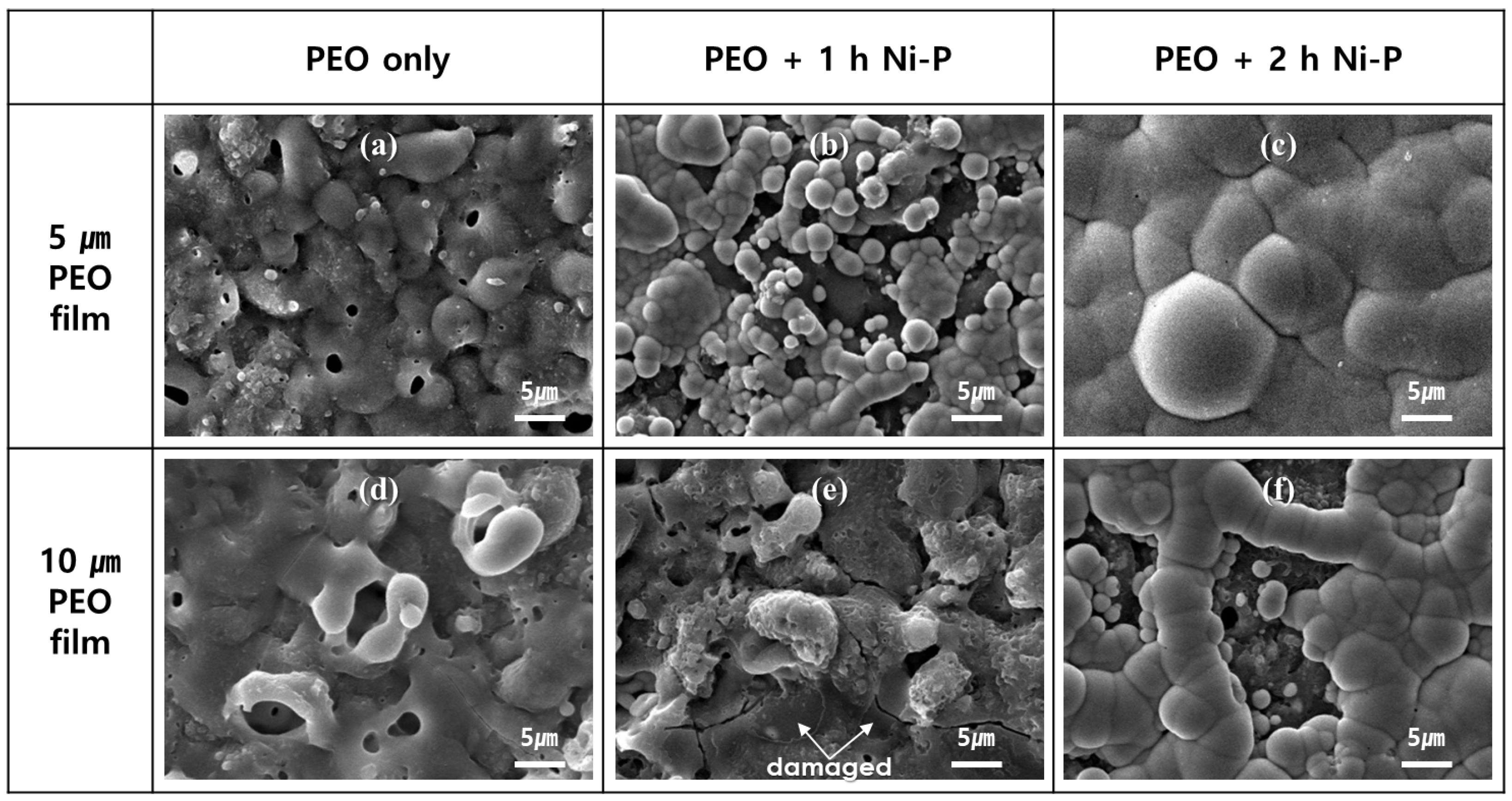
Figure 2 exhibits the surface morphologies of PEO films before and after electroless Ni-P deposition. Several pores with a diameter between 1 and 5 μm were observed on the PEO films. The size of the pores and the number of cracks increased and the number of pores decreased with increasing PEO film thickness. The presence of large size pores and a large number of cracks on the 10 μm PEO film may explain why it is a little darker than the 5 μm PEO film.
Ni-P deposited for 1 h on 5 μm PEO film exhibits a local deposition of Ni-P particles which are interconnected partly or isolated, as shown in
Figure 2b. The further deposition of Ni-P for 2 h on 5 μm PEO film resulted in the formation of an Ni-P layer which covers the whole surface of 5 μm thick PEO film, thereby showing a shiny metallic color in
Figure 1c.
Ni-P particles were not observed from the surface of 10 μm thick PEO film after 1h electroless Ni-P deposition, and instead a larger number of cracks, the widening of cracks, and surface damages of delamination and roughening were observed, as depicted in
Figure 2e. The change in color from grey to black is attributed mainly to the delamination and roughening of the PEO film surface and partly to the increased number of cracks and the widening of cracks.
The electroless deposition of Ni-P for 2 h on the 10 μm PEO film resulted in the formation of Ni-P particles which are interconnected or isolated, as demonstrated in
Figure 2f. The formation of Ni-P particles over the 10 μm PEO film changed the color from black (
Figure 1e) to a metallic grey color (
Figure 1f).
Figure 3 displays the cross-sectional morphologies of PEO films without (
Figure 3a,d) and with electroless Ni-P deposition for 1 h (
Figure 3b,e) and for 2 h (
Figure 3c,f). Ni-P deposits were observed to be aligned along the oxide/substrate interface. Embedded Ni-P particles with irregular shapes and sizes up to several micrometers were also observed within the PEO films. The Ni-P layer was partly formed on the surface of PEO films (
Figure 3b,f). The Ni-P layer was formed and covered the whole surface of 5 μm thick PEO film after 2 h deposition (
Figure 3c).
Some pores within the PEO films were not filled with an Ni-P deposit. Assuming that Ni-P particles can be precipitated only at the zincate layer which was formed at the oxide/substrate interface, the remaining pores within the PEO film after Ni-P deposition for more than 2 h do not seem to be connected with the oxide/substrate interface.
It was noted that 1 h of electroless Ni-P deposition can fill the pores within the 5 μm PEO film, but a longer electroless Ni-P deposition time of more than 2 h is necessary to fill the pores within the 10 μm PEO film and to form an Ni-P layer over the PEO film.
Figure 4 presents the surface roughness(R
a) of PEO-treated specimens with electroless Ni-P deposition time. The surface roughness of 5 μm thick PEO film was not changed significantly by1 h electroless Ni-P deposition, but it showed a noticeable decrease by 2 h electroless Ni-P deposition, which is attributed to the formation of continuous Ni-P layers over the 5 μm PEO film. The surface roughness of the 10 μm thick PEO film was larger than that of the 5 μm PEO film and it increased somewhat with 2 h electroless Ni-P deposition. The slight increase of surface roughness by 2 h electroless Ni-P deposition for 10 μm thick PEO film is ascribed to the non-uniform deposition of Ni-P particles, as shown in
Figure 2f.
3.2. Tribological Behaviors of PEO-Treated Al1050 Alloy without and with Ni-P Deposits
Figure 5 shows appearances of 5 and 10 μm thick PEO films without and with Ni-P deposits after a 100 m ball-on-disc test. After the ball-on-disc test, a wear track was observed clearly from 5 μm thick PEO film-covered specimens (
Figure 5a–c). The wear track was slightly visible for 10 μm thick PEO film (
Figure 5d) and it almost disappeared, leaving only four small white spots at the track for 1 h Ni-P deposited 10 μm PEO film (
Figure 5e). However, the wear track appeared clearly again for the 2 h Ni-P deposited 10 μm PEO film (
Figure 5f).
The width of the wear track on PEO films decreased with increasing PEO film thickness. The width of wear track became larger by Ni-P particles deposited locally, as can be seen in
Figure 5b,f. The wear track width became narrower as a result of the Ni-P layer covering the whole surface, as depicted in
Figure 5c.
The wear track was observed by SEM and the results are given in
Figure 6. Small grooves were partly formed on the 5 and 10 μm PEO films and on the 1h Ni-P deposited 10 μm thick PEO film. Wider and shallower circular wear tracks were formed on the 5 μm PEO film + 1h Ni-P deposited and 10 μm PEO film + 2h Ni-P deposited specimens, and they showed discontinuous sliding lines and deformed substrate with partly redeposited lumps. This suggests that the main wear mechanism for the Ni-P particle deposited PEO samples is by adhesion. In contrast, deeper and narrower circular abrasion grooves with continuous sliding lines were observed at the wear track of the 5 μm PEO film + 2h Ni-P deposited specimen.
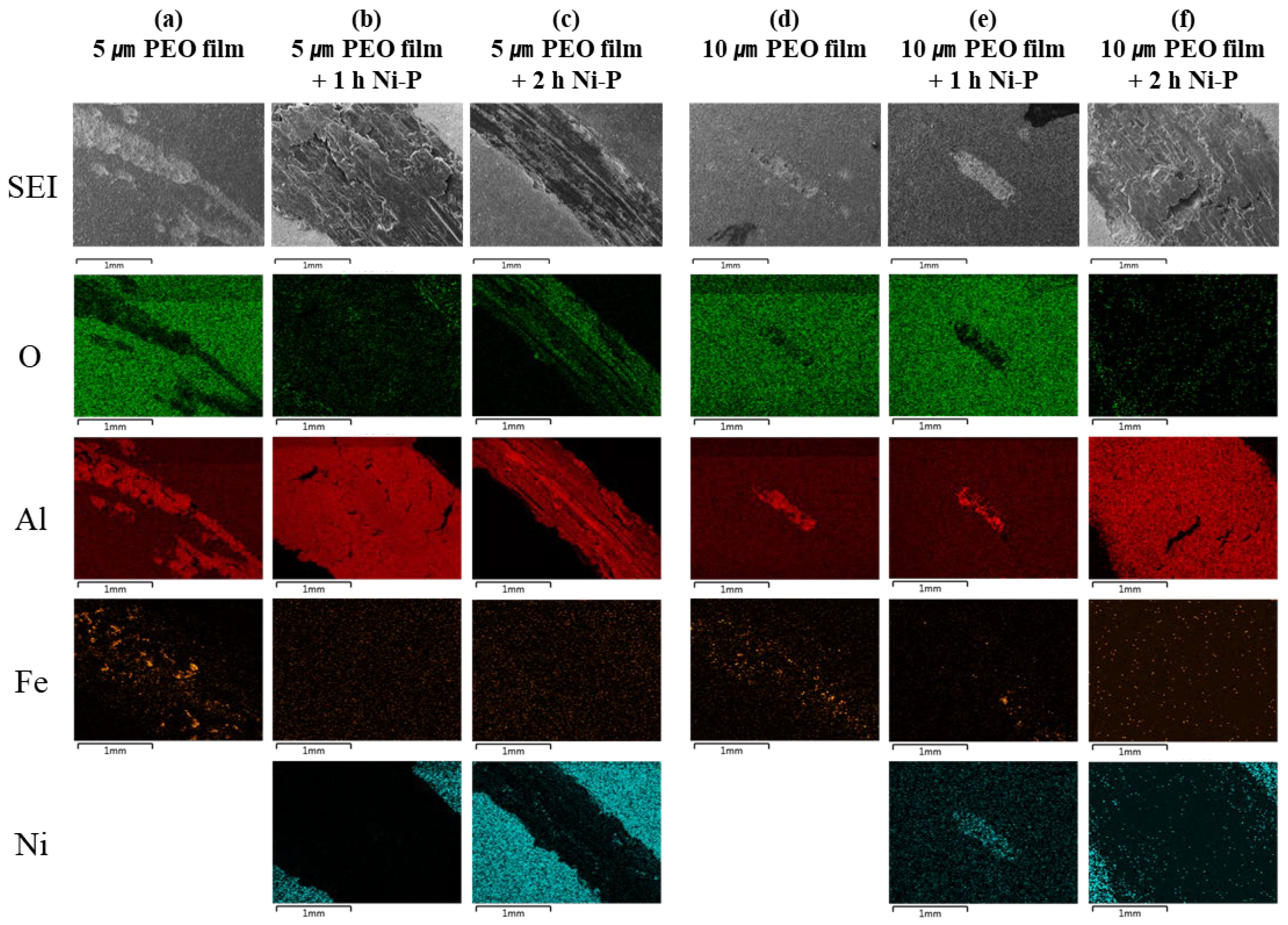
The wear track was analyzed by energy dispersive spectroscopy(EDS) and the distribution of O, Al, Fe and Ni is displayed in
Figure 7. Aluminum was observed at the abrasion groove, revealing that the PEO film could be worn out partly at the wear track by the 100 m ball-on-disc wear test. Iron was not detected at the wear track of Ni-P deposited PEO films, but it was detected at the wear track of 5 and 10 μm PEO films, suggesting that the steel ball was also worn out by the PEO films [
17]. Nickel was observed at the wear track of 10 μm PEO film + 1h Ni-P deposited specimen (
Figure 7e), revealing that the embedded Ni-P in the PEO film was exposed after the wear test.
Weight loss data after the 100 m ball-on-disc wear test are given in
Figure 8. The weight losses of the 5 and 10 μm PEO films are 0.36 mg and 0.01 mg, respectively (see insert in
Figure 8). The 1 h Ni-P deposited 10 μm PEO film-covered specimen also showed a very small amount of weight loss of about 0.31 mg. These indicate that the PEO films provide excellent abrasion resistance against the steel ball under 10 N of applied load. It should be pointed out that the PEO films can’t be worn out readily, although Ni-P is deposited in the pores of the PEO films and it is not grown up to the external surface of the PEO films.
In contrast, a large amount of weight losses appeared when the Ni-P particles or Ni-P layers covered the PEO film surface. This implies that wear occurs significantly if the Ni-P particles or Ni-P layer contact dynamically with the steel ball at 0.1 m/s under 10 N of applied load. In conclusion, PEO films can be easily worn out only when Ni-P fills the pores within the PEO films and when it is exposed to the external surface of the PEO films. An extremely substantial amount of weight loss was obtained when the thick Ni-P layer covers the PEO film entirely, as shown in
Figure 8, which is attributed to the formation of deep grooves and the much higher density of Ni than that of the porous anodic oxide layer.
The large amount of weight loss for the specimens with Ni-P deposits over the PEO films in
Figure 8 should result from the high friction between the specimen surface and the steel ball. This is strongly supported by high friction coefficients obtained from the 1 h Ni-P deposition + 5 μm PEO film-covered and 2 h Ni-P deposition + 10 μm PEO film-covered specimen surfaces in
Figure 9. Although the PEO films (
Figure 9a) and Ni-P layer-covered PEO film (
Figure 9c) showed relatively lower friction coefficients between 0.4 and 0.6, the wear loss of the Ni-P layer + PEO film-covered specimen surface was much larger than that of the PEO film surface. The reason why the Ni-P layer + PEO film-covered specimen show extremely large wear loss in
Figure 8 could be related to the formation of deep abrasion grooves and the much higher density of the Ni-P layer than the PEO films.
4. Conclusions
In this work, the surface color, surface and cross-sectional morphologies and surface roughness of PEO films and Ni-P deposits on the PEO-treated Al1050 alloy were investigated, and tribological behaviors of the PEO-treated Al1050 alloy surface without and with Ni-P deposits were examined by a ball-on-disc test.
PEO films show a grey color, and electroless Ni-P deposition for 1 h on 10 μm thick PEO film changed the surface color from grey to black. The delamination and roughening of the PEO film surface and widening of the cracks during the electroless Ni-P deposition process were observed, which seems to contribute to the change of color from grey to black. A lot of different shapes and sizes of Ni-P particles were observed to be aligned along the oxide/substrate interface. The surface roughness of the PEO film increased slightly as the result of the non-uniform deposition of Ni-P particles, and it decreased by the formation of a continuous Ni-P layer over the PEO film surface.
After a 100 m ball-on-disc test, a few discontinuous abrasion grooves with narrow width were observed at the wear tracks of PEO films if the Ni-P layer was not exposed to the top surface of PEO films, while a wide and shallow circular abrasion groove with discontinuous sliding lines and partly redeposited lumps was formed when the Ni-P particles are exposed to the top surface of the PEO films. The wear track formed on the Ni-P layer-covered surface showed a narrow and deep abrasion groove with continuous sliding lines. Iron was detected at the wear track of 5 and 10 μm PEO films without an Ni-P deposit, suggesting that the steel ball is also worn out by the PEO films during the ball-on-disc test. An extremely large amount of weight loss was obtained in the Ni-P layer-covered PEO film surface, which is attributed to the high density and low hardness of the Ni-P layer.
Author Contributions
Conceptualization, J.K., D.K and S.M.; investigation, J.K., D.K.; writing—original draft preparation, J.K.; writing—review and editing, D.K., H.V.P. and S.M.; supervision, S.M. and H.-C.S. All authors have read and agreed to the published version of the manuscript.
Funding
This research was financially supported by the Korea Institute of Materials Science and by the Technology Development Program of the Ministry of SMEs and Startups (Grant NO. S2838879).
Institutional Review Board Statement
Not applicable.
Informed Consent Statement
Not applicable.
Data Availability Statement
Data is contained within the article.
Conflicts of Interest
The authors declare that they have no conflict of interest.
References
- Yerokhin, A.L.; Nie, X.; Leyland, A.; Matthews, A.; Dowey, S.J. Plasma electrolysis for surface engineering, Surface and Coatings Technology. Surf. Coat. Technol. 1999, 122, 73–93. [Google Scholar] [CrossRef]
- Matykina, E.; Arrabal, R.; Mohedano, M.; Mingo, B.; Gonzalez, J.; Pardo, A.; Merino, M.C. Recent advances in energy efficient PEO processing of aluminium alloys. Trans. Nonferrous Met. Soc. China 2017, 27, 1439–1454. [Google Scholar] [CrossRef]
- Walsh, F.C.; Low, C.T.J.; Wood, R.J.K.; Stevens, K.T.; Archer, J.; Poeton, A.R.; Ryder, A. Plasma electrolytic oxidation (PEO) for production of anodised coatings on lightweight metal (Al, Mg, Ti) alloys. Trans. IMF. 2009, 87, 122–135. [Google Scholar] [CrossRef]
- Clyne, T.W.; Troughton, S.C. A review of recent work on discharge characteristics during plasma electrolytic oxidation of various metals. Int. Mater. Rev. 2019, 64, 127–162. [Google Scholar] [CrossRef] [Green Version]
- Moon, S.; Kim, Y. Lateral Growth of PEO Films on Al1050 Alloy in an Alkaline Electrolyte. J. Korean Inst. Surf. Eng. 2017, 50, 10–16. [Google Scholar] [CrossRef] [Green Version]
- Kwon, D.; Moon, S. Effects of NaOH Concentration on the Structure of PEO Films Formed on AZ31 Mg Alloy in PO43− and SiO32− Containing Aqueous Solution. J. Korean Inst. Surf. Eng. 2016, 49, 46–53. [Google Scholar] [CrossRef] [Green Version]
- Moon, S.; Kim, Y. PEO Film Formation Behavior of Al1050 Alloy Under Direct Current in an Alkaline Electrolyte. J. Korean Inst. Surf. Eng. 2017, 50, 17–23. [Google Scholar] [CrossRef] [Green Version]
- Moon, S.; Jeong, Y. Generation mechanism of microdischarges during plasma electrolytic oxidation of Al in aqueous solutions. Corros. Sci. 2009, 51, 1506–1512. [Google Scholar] [CrossRef]
- Xie, H.J.; Cheng, Y.L.; Li, S.X.; Cao, J.H.; Cao, L. Wear and corrosion resistant coatings on surface of cast A356 aluminum alloy by plasma electrolytic oxidation in moderately concentrated aluminate electrolytes. Trans. Nonferrous Met. Soc. China. 2017, 27, 336–351. [Google Scholar] [CrossRef]
- Kim, J.; Moon, S.; Shin, H. Effect of Na3PO4 Concentration on the Formation Behavior and Properties of PEO Films on AA2024. J. Korean Inst. Surf. Eng. 2020, 53, 351–359. [Google Scholar] [CrossRef]
- Cheng, Y.L.; Cao, J.H.; Mao, M.K.; Peng, Z.M.; Skeldon, P.; Thompson, G.E. High growth rate, wear resistant coatings on an Al–Cu–Li alloy by plasma electrolytic oxidation in concentrated aluminate electrolytes. Surf. Coat. Technol. 2015, 269, 74–82. [Google Scholar] [CrossRef]
- Hakimizad, A.; Raeissi, K.; Santamaria, M.; Asghari, M. Effects of pulse current mode on plasma electrolytic oxidation of 7075 Al in Na2WO4 containing solution: From unipolar to soft-sparking regime. Electrochim. Acta. 2018, 284, 618–629. [Google Scholar] [CrossRef]
- Wang, L.; Wang, G.; Dong, H.; Ye, M.; Li, X.; Liu, L.; Pan, J.; Ye, Z. Plasma electrolytic oxidation coatings on additively manufactured aluminum–silicon alloys with superior tribological performance. Surf. Coat. Technol. 2022, 435, 128246. [Google Scholar] [CrossRef]
- Hakimizad, A.; Raeissi, K.; Golozar, M.A.; Lu, X.; Blawert, C.; Zheludkevich, M.L. The effect of pulse waveforms on surface morphology, composition and corrosion behavior of Al2O3 and Al2O3/TiO2 nano-composite PEO coatings on 7075 aluminum alloy. Surf. Coat. Technol. 2017, 324, 208–221. [Google Scholar] [CrossRef]
- Li, Q.; Liang, J.; Liu, B.; Peng, Z.; Wang, Q. Effects of cathodic voltages on structure and wear resistance of plasma electrolytic oxidation coatings formed on aluminium alloy. Appl. Surf. Sci. 2014, 297, 176–181. [Google Scholar] [CrossRef]
- Moon, S.; Kim, J.; Shin, H. Effect of form of applied current on the formation behavior of PEO films on Al6082 alloy. J. Korean Inst. Surf. Eng. 2022, 55, 9–17. [Google Scholar] [CrossRef]
- Habazaki, H.; Tsunekawa, S.; Tsuji, E.; Nakayama, T. Formation and characterization of wear-resistant PEO coatings formed on β-titanium alloy at different electrolyte temperatures. Appl. Surf. Sci. 2012, 259, 711–718. [Google Scholar] [CrossRef]
- Yang, C.; Zhu, J.; Cui, S.; Chen, P.; Wu, Z.; Ma, Z.; Fu, R.K.Y.; Tian, X.; Chu, P.K.; Wu, Z. Wear and corrosion resistant coatings prepared on LY12 aluminum alloy by plasma electrolytic oxidation. Surf. Coat. Technol. 2021, 409, 126885. [Google Scholar] [CrossRef]
- Li, X.J.; Zhang, M.; Wen, S.; Mao, X.; Huo, W.G.; Guo, Y.Y.; Wang, Y.X. Microstructure and wear resistance of micro-arc oxidation ceramic coatings prepared on 2A50 aluminum alloys. Surf. Coat. Technol. 2020, 394, 125853. [Google Scholar] [CrossRef]
- Treviño, M.; Garza-Montes-de-Oca, N.F.; Pérez, A.; Hernández-Rodríguez, M.A.L.; Juárez, A.; Colás, R. Wear of an aluminium alloy coated by plasma electrolytic oxidation. Surf. Coat. Technol. 2012, 206, 2213–2219. [Google Scholar] [CrossRef]
- Sabatini, G.; Ceschini, L.; Martini, C.; Williams, J.A.; Hutchings, I.M. Improving sliding and abrasive wear behaviour of cast A356 and wrought AA7075 aluminium alloys by plasma electrolytic oxidation. Mater. Des. 2010, 31, 816–828. [Google Scholar] [CrossRef]
- Xue, W.; Du, J.; Wu, X.; Lai, Y. Tribological behavior of microarc oxidation coatings on aluminum alloy. ISIJ Int. 2006, 46, 287–291. [Google Scholar] [CrossRef] [Green Version]
- Sopchenski, L.; Robert, J.; Touzin, M.; Tricoteaux, A.; Olivier, M.-G. Improvement of wear and corrosion protection of PEO on AA2024 via sol-gel sealing. Surf. Coat. Technol. 2021, 417, 127195. [Google Scholar] [CrossRef]
- Polunin, A.V.; Cheretaeva, A.O.; Borgardt, E.D.; Rastegaev, I.A.; Krishtal, M.M.; Katsman, A.V.; Yasnikov, I.S. Improvement of oxide layers formed by plasma electrolytic oxidation on cast Al-Si alloy by incorporating TiC nanoparticles. Surf. Coat. Technol. 2021, 423, 127603. [Google Scholar] [CrossRef]
- Fernández-López, P.; Alves, S.A.; Azpitarte, I.; San-José, J.T.; Bayón, R. Corrosion and tribocorrosion protection of novel PEO coatings on a secondary cast Al-Si alloy: Influence of polishing and sol-gel sealing. Corros. Sci. 2022, 207, 110548. [Google Scholar] [CrossRef]
- Hübert, T.; Svoboda, S.; Oertel, B. Wear resistant alumina coatings produced by a sol–gel process. Surf. Coat. Technol. 2006, 201, 487–491. [Google Scholar] [CrossRef]
- Moon, S.; Kim, J. Surface Hadness Measurement of NiP-plated AA7050. J. Korean Inst. Surf. Eng. 2021, 54, 171–177. [Google Scholar] [CrossRef]
Figure 1.
Photographs of PEO-treated AA1050 specimens before and after electroless Ni-P deposition for 1 h and 2 h. (a) 5μm PEO film, (b) 5μm PEO film + 1 h Ni-P, (c) 5μm PEO film + 2 h Ni-P, (d) 10μm PEO film, (e) 10μm PEO film + 1 h Ni-P and (f) 10μm PEO film + 2 h Ni-P.
Figure 1.
Photographs of PEO-treated AA1050 specimens before and after electroless Ni-P deposition for 1 h and 2 h. (a) 5μm PEO film, (b) 5μm PEO film + 1 h Ni-P, (c) 5μm PEO film + 2 h Ni-P, (d) 10μm PEO film, (e) 10μm PEO film + 1 h Ni-P and (f) 10μm PEO film + 2 h Ni-P.
Figure 2.
Surface morphologies of PEO-treated AA1050 specimens before and after electroless Ni-P deposition for 1 h and 2 h. (a) 5 μm PEO film, (b) 5μm PEO film + 1 h Ni-P, (c) 5 μm PEO film + 2 h Ni-P, (d) 10 μm PEO film, (e) 10 μm PEO film + 1 h Ni-P and (f) 10 μm PEO film + 2 h Ni-P.
Figure 2.
Surface morphologies of PEO-treated AA1050 specimens before and after electroless Ni-P deposition for 1 h and 2 h. (a) 5 μm PEO film, (b) 5μm PEO film + 1 h Ni-P, (c) 5 μm PEO film + 2 h Ni-P, (d) 10 μm PEO film, (e) 10 μm PEO film + 1 h Ni-P and (f) 10 μm PEO film + 2 h Ni-P.
Figure 3.
Cross-sectional morphologies of PEO-treated AA1050 specimens before and after electroless Ni-P deposition for 1 h and 2 h. (a) 5 μm PEO film, (b) 5μm PEO film + 1 h Ni-P, (c) 5 μm PEO film + 2 h Ni-P, (d) 10 μm PEO film, (e) 10 μm PEO film + 1 h Ni-P and (f) 10 μm PEO film + 2 h Ni-P.
Figure 3.
Cross-sectional morphologies of PEO-treated AA1050 specimens before and after electroless Ni-P deposition for 1 h and 2 h. (a) 5 μm PEO film, (b) 5μm PEO film + 1 h Ni-P, (c) 5 μm PEO film + 2 h Ni-P, (d) 10 μm PEO film, (e) 10 μm PEO film + 1 h Ni-P and (f) 10 μm PEO film + 2 h Ni-P.
Figure 4.
Surface roughness(Ra) of PEO-treated AA1050 with electroless Ni-P deposition time.
Figure 4.
Surface roughness(Ra) of PEO-treated AA1050 with electroless Ni-P deposition time.
Figure 5.
Appearance of the PEO-treated AA1050 specimens without and with electroless Ni-P deposition for 1 h and 2 h after a 100 m ball-on-disc wear test at 0.1 m/s under 10 N of applied load. (a) 5 μm PEO film, (b) 5 μm PEO film + 1 h Ni-P, (c) 5 μm PEO film + 2 h Ni-P, (d) 10μm PEO film, (e) 10 μm PEO film + 1 h Ni-P and (f) 10 μm PEO film + 2 h Ni-P.
Figure 6.
Surface morphologies of PEO-treated AA1050 specimens without and with electroless Ni-P deposition for 1 h and 2 h after a 100 m ball-on-disc wear test at 0.1 m/s under 10 N of applied load. (a) 5 μm PEO film, (b) 5 μm PEO film + 1 h Ni-P, (c) 5 μm PEO film + 2 h Ni-P, (d) 10 μm PEO film, (e) 10 μm PEO film + 1 h Ni-P and (f) 10 μm PEO film + 2 h Ni-P.
Figure 7.
SEM images and EDS maps of the PEO-treated AA1050 specimens without (a,d) and with electroless Ni-P deposition for 1h (b,e) and 2h (c,f) after a 100 m ball-on-disc wear test at 0.1 m/s under 10 N of applied load.
Figure 7.
SEM images and EDS maps of the PEO-treated AA1050 specimens without (a,d) and with electroless Ni-P deposition for 1h (b,e) and 2h (c,f) after a 100 m ball-on-disc wear test at 0.1 m/s under 10 N of applied load.
Figure 8.
Weight loss of PEO-treated AA1050 specimens without and with electroless Ni-P deposition during the 100 m ball-on-disc wear test.
Figure 8.
Weight loss of PEO-treated AA1050 specimens without and with electroless Ni-P deposition during the 100 m ball-on-disc wear test.
Figure 9.
Changes in friction coefficient for the AA1050 specimens during ball-on-disc wear test at 0.1 m/s under 10 N of applied load: (a) PEO film only, (b) PEO film + 1 h Ni-P, (c) PEO film + 2 h Ni-P.
Figure 9.
Changes in friction coefficient for the AA1050 specimens during ball-on-disc wear test at 0.1 m/s under 10 N of applied load: (a) PEO film only, (b) PEO film + 1 h Ni-P, (c) PEO film + 2 h Ni-P.
| Disclaimer/Publisher’s Note: The statements, opinions and data contained in all publications are solely those of the individual author(s) and contributor(s) and not of MDPI and/or the editor(s). MDPI and/or the editor(s) disclaim responsibility for any injury to people or property resulting from any ideas, methods, instructions or products referred to in the content. |
© 2023 by the authors. Licensee MDPI, Basel, Switzerland. This article is an open access article distributed under the terms and conditions of the Creative Commons Attribution (CC BY) license (https://creativecommons.org/licenses/by/4.0/).


