Article

Ultrasonic-Induced Grain Refinement in Laser Cladding Nickel-Based Superalloy Reinforced by WC Particles

1
School of Mechanical Engineering, Jiangsu University, Zhenjiang 212013, China
2
Institute of Advanced Manufacturing and Modern Equipment Technology, Jiangsu University, Zhenjiang 212013, China
*
Author to whom correspondence should be addressed.
Coatings 2023, 13(1), 151; https://doi.org/10.3390/coatings13010151
Submission received: 7 December 2022 / Revised: 8 January 2023 / Accepted: 9 January 2023 / Published: 11 January 2023
(This article belongs to the Special Issue Ceramic Films and Coatings: Properties and Applications)

Abstract

:
Laser cladding was used to prepare three composite coatings, i.e., Inconel 718 nickel-based superalloy (IN718), IN718-50 wt.% WC created by adding tungsten carbide (WC) particles and IN718-50 wt.% WC assisted by ultrasonic vibration. The phase composition, microstructure evolution, microhardness, residual stress and tribological properties of the three coatings were studied. The addition of WC enhances hardness and improves tribological properties, but also causes aggregation and considerable formation of carbides associated with rough structure. Ultrasonic vibration greatly refines the solidification microstructure, as it can break the growing dendrites, reduce the aggregation of reinforced particles and refine solidified structure. The average microhardness of the latter two composite coatings was increased by 36.37% and 57.15%, respectively, compared with the first IN718 coating, and the last composite coating (ultrasonic assistance) had the lowest COF (0.494). The WC particles and refined carbides converted the wear mechanism from adhesive wear to abrasive wear. In addition, the resultant stress on the surface of the composite coating roughly doubled after adding 50 wt.% WC, and only increased by 49.53% with ultrasonic treatment. The simulation results indicate that acoustic cavitation mainly occurs in the middle and bottom of the molten pool and proper frequency ultrasonic is conducive to the generation of the cavitation effect.

1. Introduction

IN718 is a precipitate-strengthened superalloy based on Ni-Fe-Cr elements, possessing high yield strength and good resistance to heat, creep and corrosion, and therefore has been widely used in the manufacturing of gas turbine blades, engine casings, pumps and molds [1,2]. Under high-temperature, overloading and alternating-loading severe serving conditions, the failure of nickel-based alloy components is mainly caused by surface abrasion, corrosion and fatigue spalling, resulting in the scrapping of a large number of expensive mechanical parts [3,4]. Therefore, numerous surface modification techniques are used to improve surface performances of these parts to prolong service life. In recent years, with the merits of good metallurgical bonding, convenience for automation and controllable thickness, laser cladding technology has been widely used in preparing functional coatings on surfaces [5,6].
However, it is difficult for pure nickel-based coating to meet practical application requirements. Therefore, ceramic particles (such as TiC, WC, Al2O3 and ZrO2) possessing the properties of good thermal stability, high hardness and superior wear resistance are added into nickel-based alloy powder to fabricate metal-based ceramic composite coatings with excellent performance [7,8,9,10]. Therefore, WC particles having a fine affinity with nickel-based alloys are ideal materials for improving the wear properties of nickel-based coatings [11,12,13]. Xia et al. [14] studied the tribological properties of laser melting GH3536-WC composite coatings reinforced by coarse and fine WC particles, concluding that the more uniform distribution of fine WC particles can significantly enhance the effect of dispersion strengthening under the same WC content. Shen et al. [15] fabricated NiCrSiBC-WC composite coatings with different WC content to investigate the mechanism of grain refinement and crack behavior, and found that high WC content can refine solidified structures obviously while also causing increases in the tensile stress and crack susceptibility of coatings. In fact, due to the differences in physical properties between ceramic particles and Ni-based alloy as well as the rapid melting/solidification characteristics of laser cladding, metallurgical defects such as uneven distribution of WC ceramic particles, cracks and pores are more likely to appear in the composite coating [16,17,18].
Ultrasonic vibration, as a type of auxiliary field, has been applied in the solidification process of molten metal to refine the growth of microstructures via the synergistic effect of ultrasonic cavitation and acoustic streaming [19,20]. Based on mathematical deduction and analysis, Zhu et al. [21] proposed that the degree of undercooling and nucleation rate of the molten pool increase with increasing amplitude and frequency of the ultrasonic vibration. Moreover, Fan and Chen et al. [22] conducted a series of experiments on ultrasonic-field-assisted gas tungsten arc cladding high-entropy alloys and found that the size of grains and crystal boundary decrease with an increase in ultrasonic power. In addition, the acoustic streaming and thermal effect of ultrasonic in the molten pool were studied using numerical simulation. At present, most research mainly focuses on the field of pure superalloy coating, while the mechanism of ultrasonic vibration on the distribution and decomposition of reinforced particles as well as the morphologies of precipitated carbides in the composite coatings is still insufficiently studied.
In this study, IN718 coating, IN718-50 wt.% WC and IN718-50 wt.% WC (ultrasonic assistance) composite coatings were prepared by laser cladding. The phase composition, microstructure evolution, microhardness, wear resistance and residual stress of the three coatings were investigated. In addition, both the sound pressure distribution and cavitation process in the molten pool were analyzed by numerical simulation.

2. Materials and Methods
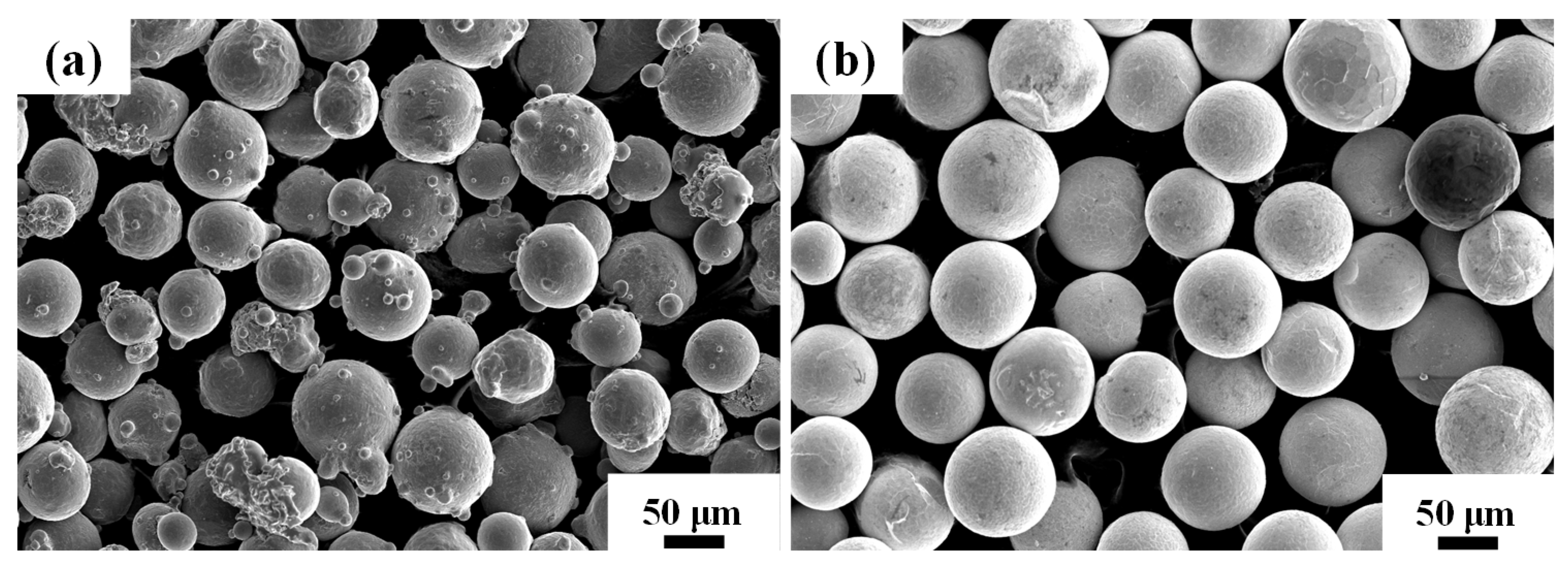
2.1. Materials

The raw materials were spherical IN718 alloy powder (particle size: 40–100 µm) and spherical WC particles (particle size: 30–70 µm), as shown in Figure 1, which were then mechanically mixed by a planetary ball mill for 180 min. Finally, the mixed powder was dried in a vacuum drying oven at 373.15 K for 30 min. The chemical composition of bonding metal IN718 alloy powder is shown in Table 1. The forged In718 alloy with the dimensions of 58 mm × 38 mm × 6 mm was used as the substrate. Before the experiment, the surface of the substrate was grinded with sandpaper and washed with acetone solution to remove oil stains.

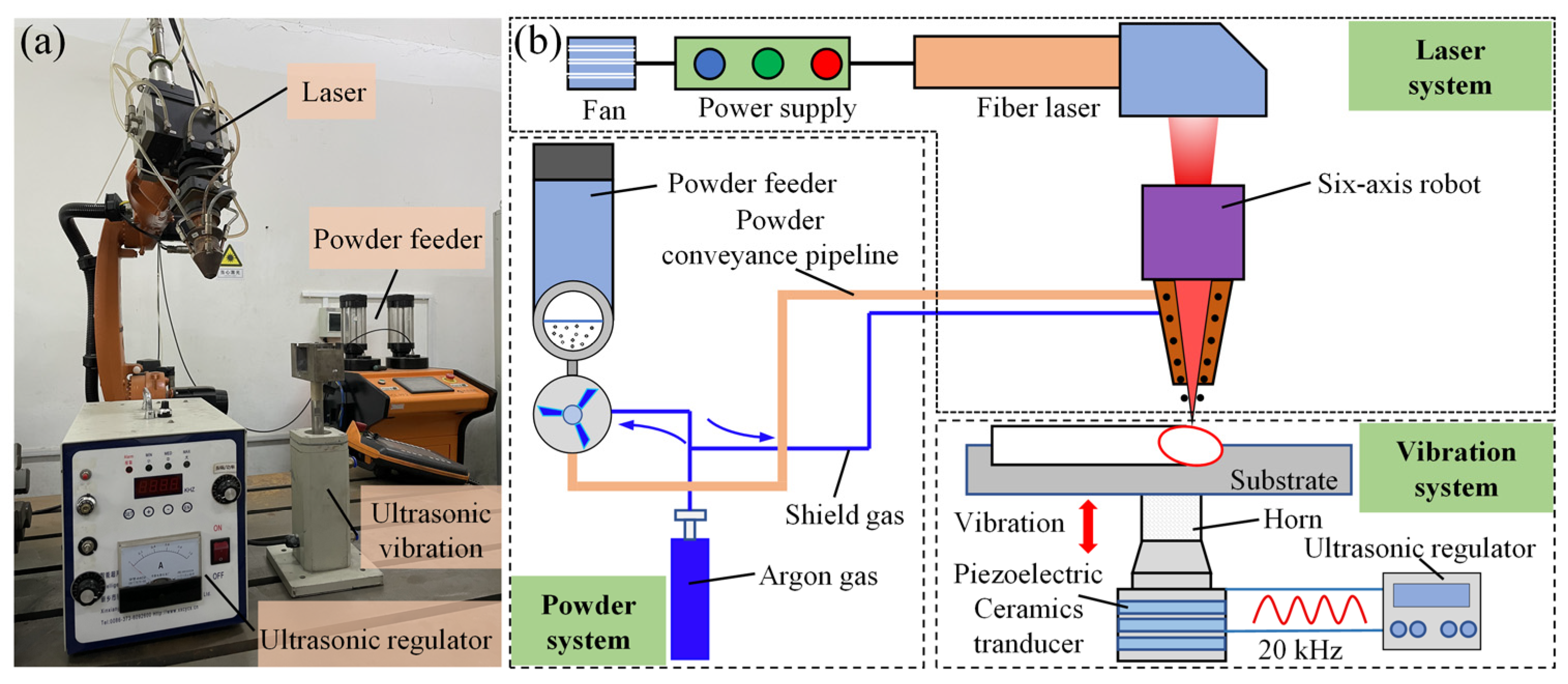
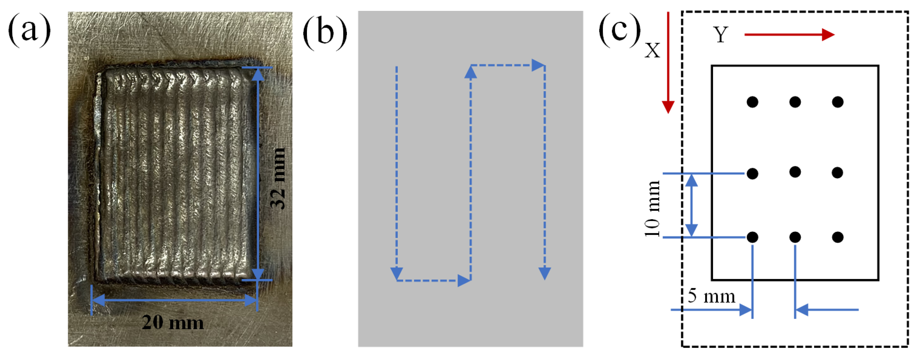
2.2. Experimental Procedure

The experiment was carried out on a composite device, and the details of the overall layout diagram are shown in Figure 2. The whole device is composed of two parts, including the laser cladding system and the ultrasonic vibration device. The laser cladding system consists of a continuous fiber laser (IPG-YLS-2000-TR, Ipg Photonics Corporation, Oxford, MA, USA), a powder feeder (Acunity, Acunity GmbH, North Rhine-Westphalia, Germany) and a six-axis industrial robot (KUKA, KUKA Schweissanlagen, Augsburg, Germany). The ultrasonic vibration device (CYCS-300TJ, Chiyu Ultrasonic Equipment, Jinhua, China) is composed of a piezoelectric transducer, an acoustic horn and an ultrasonic regulator. The resonant frequency of ultrasonic generator is adjustable from15 kHz to 60 kHz, and the maximum amplitude is 30 µm. The perpendicular relation and tight junction between the horn and the substrate were double-checked before the experiment to ensure the introduction of ultrasonic.
Based on the optimization results of previous experiments, the process parameters of laser cladding are listed in Table 2 [18,20,23]. The IN718 coating, IN718-50 wt.% WC and IN718-50 wt.% WC (ultrasonic assistance) composite coatings were fabricated, and were marked as Coating A, Coating B and Coating C, respectively. Figure 3a,b show their dimensions and the scanning strategy, respectively. Moreover, all coatings and the single track were fabricated using the same process parameters of laser cladding.

2.3. Microstructure and Properties Characterization

Samples were prepared using wire-cutting machine for metallographic observation and phase detection. The metallographic samples were etched by aqua regia solution (HCl: HNO3 = 3: 1) for 220 s to observe the microstructure under scanning electron microscopy (SEM, S-3400N, Japan) and optical microscope (OM, Axio-Lab.A1, Carl Zeiss AG, Baden-Wurttemberg, Germany). X-ray diffractometer (XRD, Bruker D8 Advance, Bruker, Karlsruhe, Germany) was used to analyze the phase of coatings. The residual stress on the surface of coatings was obtained by the sin2ψ method with a Proto-LXRD instrument (X-350A, Aurora Group Company, Vancouver, Canada). The high voltage of the X-ray was 22 kV and the current was 6 mA. Cr-Kα characteristic X-ray filtered by nickel and the diffraction plane 220 were utilized for the measurement. The stress constant was −601 MPa/deg.
The mechanical properties of different coatings were measured by Vickers microhardness tester (MHVS-1000BZ, Yizhong Precision Instrument, Shanghai, China) and friction and wear tester (HT-1000, Kaihua Technology Company, Lanzhou, China). The load and hold time of the microhardness test were set as 0.2 kg and 15 s, respectively. Before friction and wear test, the surface of coatings was grounded with sandpapers from 400# to 2000# and then polished with diamond polishing agents to obtain high-quality smooth surface. In addition, the material of grinding balls (φ = 5 mm) was Si3N4. The wear tests were carried out with a load of 1500 g and a constant duration of 20 min.

3. Results and analysis

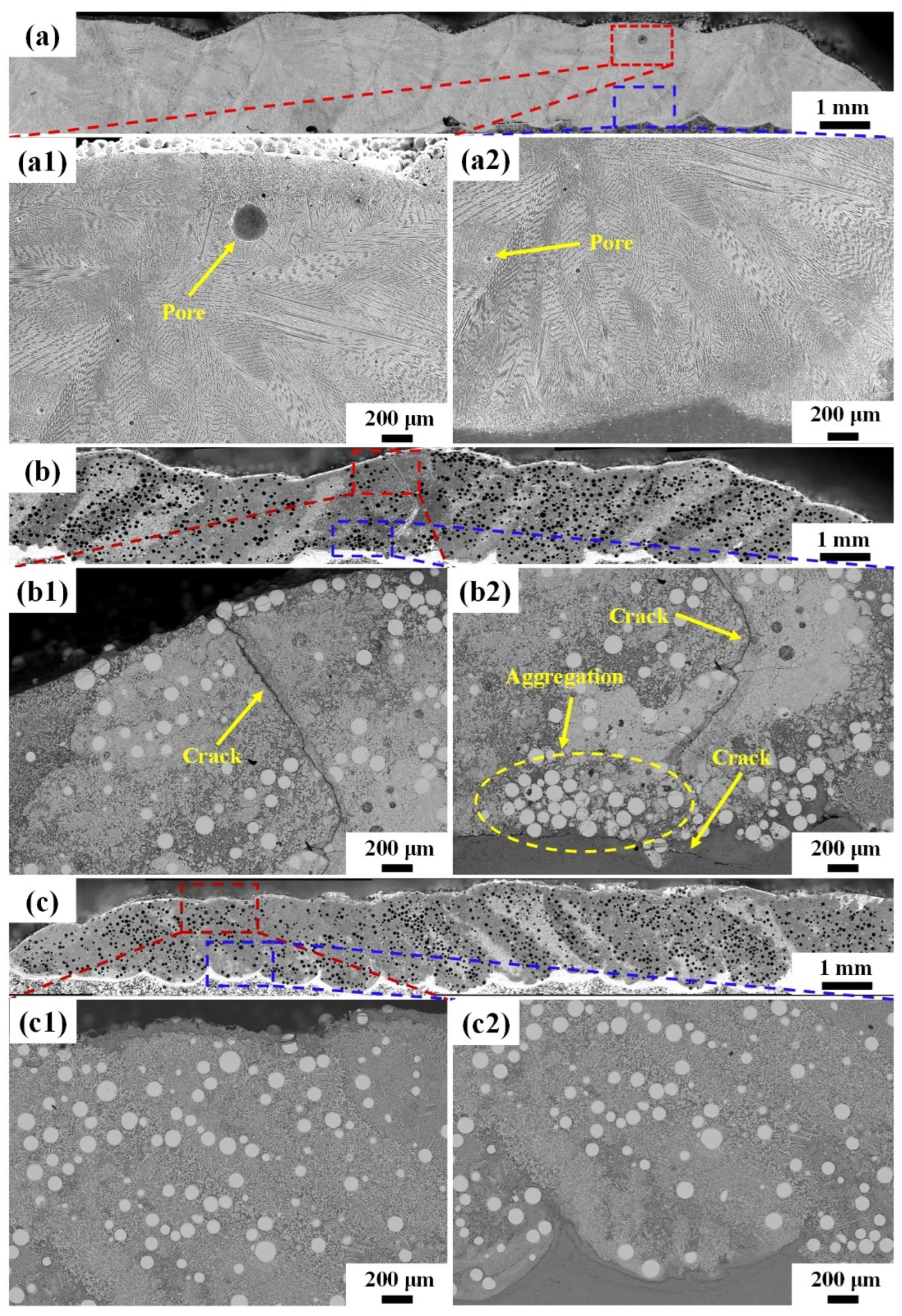
3.1. Cross-Sectional Morphologies of Different Coatings

Figure 4 shows the cross-sectional morphologies of three coatings fabricated by laser cladding. It can be found that Coating A contains many pores, while the main defects of Coating B are longitudinal and transverse cracks, as shown in Figure 4a,b. Due to the rapid solidification in the laser cladding process, pores are caused by shielding gas and air which cannot escape out of the molten pool in time, as shown in Figure 4(a1,a2). Under natural conditions, melt flow in the molten pool is not strong enough to overcome agglomeration and sedimentation of WC particles because of considerable density differences (Table 3), as shown in Figure 4(b2). Carefully observing Figure 4(b1,b2), it can be seen that transverse cracks occur at the interface between the coating and the substrate, while longitudinal cracks are observed in the overlapping area. The longitudinal cracks propagate in the direction of the highest temperature gradient, i.e., the preferentially growing direction of dendrites, and then penetrate the whole composite coating. The transverse cracks are induced by the difference of the coefficient of thermal expansion in different regions, especially the reinforced WC particles which tend to cluster toward the bottom of the coating. The micro-jetting and acoustic streaming generated by ultrasonic can effectively promote the internal flow of the melt pool, and thus the WC particles are relatively evenly distributed across the cladding layer. In addition, there are no obvious pores and cracks in the cross-section of the coating, as shown in Figure 4c.

3.2. Microstructure of Coatings

3.2.1. Phase Composition Analysis

Figure 5a shows the XRD patterns of the three coatings. Tungsten carbide particles possessing high thermal stability and chemical inertness experience almost no conversion or chemical reactions under individual heating. The possible decomposition reactions of WC particles in the molten pool were calculated using HSC thermodynamic software. The Gibbs free enthalpy (ΔG) of WC decomposing into W2C and WC turns out to be negative only when temperature surpasses 2614 K (as shown in Figure 5b), which means this reaction can proceed spontaneously with the rise in temperature. However, with strong thermal convection and high-density energy in the molten pool, tungsten carbide particles can decompose into W2C even at low temperatures (873 K~1143 K), as reported by Nerz et al. [24]. The free enthalpy of decarburization reaction (2) is positive, which means that it cannot proceed spontaneously without external force. In fact, the non-equilibrium solidifying characteristics of the laser cladding process, including high cooling rate (up to 7800 K/s) and strong thermal convection (up to 0.5 m/s) induced by the Marangoni effect, promote the forward process of the reaction [25,26].
2 WC W 2 C + C
W 2 C 2 W + C
WC + W + L M 3 W 3 C
M + C MC
where L means Fe-C liquid phase and M means Cr elements in the IN718 alloy.
Therefore, under high-intensity laser irradiation, WC decomposes into W2C and C at the beginning, and then the intermediate product (W2C) proceeds to undergo the decarburization reaction. During the dynamic decomposition process, the W and C elements can react with the active elements (such as Fe, Mo and Cr elements) in the molten pool to precipitate carbides with different shapes and crystalline structures. The XRD pattern shows that the dominant phase in Coating A is Fe0.64Ni0.36 supersaturated solid solution (namely γ-Ni). With the addition of numerous WC particles, the phases of Coating B and Coating C are mainly γ-Ni, WC, W2C, M6C (Fe3W3C and Fe3Mo3C), M7C3 (Cr7C3) and M23C6 (Cr23C6) [15,27].
Attentive examination of Figure 5a reveals some detailed information: the main peak position of Coating A is 50.7038° and those of Coating B and Coating C are 39.7464° and 39.7656°, respectively. The left shift of the diffraction peak is closely related to the increase in residual stress caused by a considerable number of precipitated carbides, which is consistent with prior studies [14,25]. The mean grain size of the coating can be deduced from the Scherrer equation [28]. The full width at half maximum (FWHM) of the XRD diffraction peak is calculated by
L = 0.9 λ β cos θ
where L is the mean grain size, λ is the X-ray wavelength, β is the FWHM and θ is half the scattering angle. According to this equation, the FWHM is inversely proportional to the mean grain size. Fitting the main peaks of XRD curves using Gaussian functions, the FWHM values of Coatings A, B and C are measured to be 0.31849, 0.25541 and 0.26437, respectively. Therefore, the mean grain size of the three coatings first increases and then decreases. It is noted that the grain size of precipitated carbides is generally larger than the γ-Ni phases of IN718 alloy, and this kind of microstructure is more refined with the application of ultrasonic (as is shown in Figure 6), corresponding with the above inference.

3.2.2. Microstructure Analysis

The typical microstructure of Coating A is shown in Figure 6. According to the constitutional supercooling criterion, the morphology of a solidified structure depends on the combined parameters of temperature gradient G and solidification rate R [29]. The solidification rate R is defined as the rate of normal advance at the solidification interface, which can be expressed as [26]:
R = V s i n
where Vs, i and n* correspond to the laser scanning velocity, the unit vector of scanning direction and the interface normal vector of the solidification front, respectively. Therefore, the value of solidification rate R gradually decreases in the depth direction. The surface of the molten pool is at the gas–liquid interface where it is affected by a strong dual action of thermal radiation and thermal convection, while the interior is mainly affected by thermal convection caused by the Marangoni effect. As a result, the temperature gradient G gradually decreases in the depth direction. The morphology of the solidified structure is determined by the morphological parameters G/R; the larger the value, the rougher the microstructure. Meanwhile, the size of the solidified structure decreases with the increase in the cooling rate G × R [30]. Therefore, the microstructure of Coating A sequentially presents as fine equiaxed grains, dendritic crystal and coarse columnar grains from the top to bottom of the coating, as shown in Figure 6(a1–a3).
When adding 50 wt.% WC particles, the microstructure undergoes a dramatic shift from single γ-Ni solid solution phase to a large number of precipitated carbides. At the top region of Coating B, the direct laser radiation and endothermic decomposition of tungsten carbide both promote the higher temperature gradient G and cooling rate G × R around WC particles [14]. Thus, WC particles act as heterogeneous nucleation sites for precipitated carbides which appear as long columnar and large block carbides with sharp edges, as shown in Figure 6(b1). Due to the addition of a high content of WC particles, obvious cracks and pores occur in the cluster regions of multiple particles at the middle region of Coating B, as shown in Figure 6(b2). It is noted that cracks initiate at the edges of WC particles and gradually extend to the interior, presenting as brittle fracture of multiple clustered particles. These phenomena are mainly related to local stress concentration and poor flowability of IN718 melt caused by the agglomeration of WC particles [15,27]. At the bottom region of Coating B, the WC particles with high density tend to sink, and the precipitated carbides become granular and columnar in shape rather than block-shaped, and clustered in flocculent and chrysanthemum shapes. In addition, mixed microstructures such as feather-like, long columnar and large block carbides with obvious dendrite orientation form, as shown in Figure 6(b3).
After introducing ultrasonic vibration into the molten pool, the solidified microstructure is refined, apparently because of the synergetic effects between acoustic streaming and cavitation. The acoustic streaming and micro-jet emitted by the collapse of cavitation bubbles both accelerate the thermal convection of the molten pool, which is conducive to reducing the temperature gradient G. Thus, plenty of fine equiaxed carbides are generated at the top of Coating C, as shown in Figure 6(c1). Moreover, the solidification rate R decreases with increasing depth, which leads to the formation of columnar carbides. The refinement of the microstructure is more remarkable at the bottom region associated with less ultrasonic attenuation, as shown in Figure 6(c2,c3). The epitaxial growth of dendrites as well as the large block eutectic carbides are broken on the side near the bottom. In addition, fine dispersed carbides in the shape of cells and arborization are generated.
A map scanning analysis of a whole WC particle and the surrounding area in the metal-base ceramic coatings was carried out, as shown in Figure 7. A dissolution–diffusion layer can be obviously observed around the WC particle, with strips and blocks of tungsten-rich dendrites growing perpendicular to the edges. The W elements are mainly enriched in the surrounding bright white carbides, while the Cr, Fe and C elements are relatively evenly distributed within the coatings. Based on previous studies [18,31], five main phases are observed in Figure 7, namely the bright white tungsten carbide phase (1), the white W2C phase in the dissolved diffusion layer (2), the block as well as striped eutectic carbide phases (3) and (4), and the dark grey IN718 matrix phase (5). The eutectic carbide phase is produced by the metallurgical combination of W elements released by the thermal decomposition of WC with elements from IN718 alloy at locations relatively far from the WC particles, and contains more Fe, Cr and Ni elements. The chemical compositions of typical phases are shown in Table 4. The results show that the weight ratio of W and C elements in the block carbide is higher than that of the strip carbide, which contains more Nb and Cr elements.
Several typical decomposition characteristics of WC particles are generalized according to the microstructure SEM images in different coatings, as shown in Figure 8. Figure 8a,c are extracted from Coating B, while the others are from Coating C. Firstly, WC particles with a small size are prone to experiencing disintegration and diffusion at high thermal energy densities, while the decomposition type of large WC particles is dissolution–diffusion. Secondly, the main differences between Coating B and Coating C are the morphologies and sizes of precipitated carbides. In Figure 8a, the splitting decomposition of small-scale WC particles occurs at a high temperature, then reacts with the active elements in the IN718 matrix, which finally precipitate large block carbides with sharp edges and microcracks. However, when ultrasonic is introduced into the molten pool, the edges of carbides become more rounded and their size reduces, as shown in Figure 8b. The same phenomenon can be found in the morphology of the large WC particles. During the cladding process, the energy in the molten pool is not sufficient to cause complete dissolution of large WC particles. The borders of the WC particle are slightly eroded by molten IN718 alloy and form a shallow alloyed reaction layer which is mainly composed of the intermediate product (W2C) from the decarburization reaction of tungsten carbide. At the same time, the surrounding carbides present as block and strip shapes, as shown in Figure 8c. In Figure 8d, the decomposition of WC particles increases obviously because of the completely disappearance of the shell-core structure, and rounded carbides nucleated at the WC particle grow radially after ultrasonic treatment. Meanwhile, the microstructure and size of precipitated carbides are generally refined.

3.3. Performance of Composite Coating

3.3.1. Microhardness

Figure 9 shows the microhardness distribution along the depth direction of the three coatings. The average microhardness of Coatings A, B and C is 304.27 HV0.2, 414.93 HV0.2 and 478.15 HV0.2, respectively. The microhardness of Coating C increases by 63.22 HV0.2 (15.25%) compared with Coating B and is 1.36 times that of Coating A. The enhancement of microhardness in Coating B and Coating C can be ascribed to a large number of precipitated carbides after the addition of WC particles. According to the Hall–Petch formula [32], there is a nonlinear inverse relationship between microhardness and grain size. Thus, the microstructure refinement caused by ultrasonic, as shown in Figure 6, can effectively enhance the microhardness of Coating C. Meanwhile, the fluctuation of microhardness along the depth direction is gentle, which indicates that the homogenization of particle distribution and microstructure has improved significantly.

3.3.2. Residual Stress

The residual stress of WC-reinforced composite coatings prepared by laser cladding was made up of two parts: thermal stress and shrinkage stress [31]. Thermal stress was generated due to high-temperature ingredients, especially at the interface between the coating and the substrate, while shrinkage stress was induced by the incompatible coefficient of thermal expansion between carbides and nickel-based alloy [15,33]. The generation mechanism of residual stress is shown in Figure 10. Basing on the laser scanning path shown in Figure 3b, the direction along the laser scanning path was set as x, while that perpendicular to it was set as y. Nine points selected evenly on the surface of coatings were measured to obtain the average residual stress. Then, the residual stress component of x direction was set as σx, and the residual stress component of y direction was set as σy. Eventually, the resultant stress—which was the vector sum of σx and σy—was set as σt, as shown in Figure 11.
The results indicate that residual tensile stresses are widespread on the surface of coatings, and the residual stress component σx is the principal stress, similar to the results of previous studies [34]. With the addition of numerous WC particles, σx and σy of Coating B increased significantly. It is noteworthy that the gap between σx and σy on Coating C decreased due to the homogenized effect of ultrasonic. Based on the synthesis results, the resultant stress σt for Coating A was 237.19 MPa, while these values increased to 460.43 MPa and 354.68 MPa for Coating B and Coating C, respectively. According to previous studies, the bulk precipitated carbides with sharp edges and uneven distribution of WC particles all increase residual stress levels [14,33]. In short, the distribution of WC particles was improved, and the formation of bulk precipitated carbides with sharp edges was inhibited by ultrasonic, as shown in Figure 6 and Figure 8. Therefore, the resultant stress σt of Coating C showed a 22.95% decrease compared with Coating B.

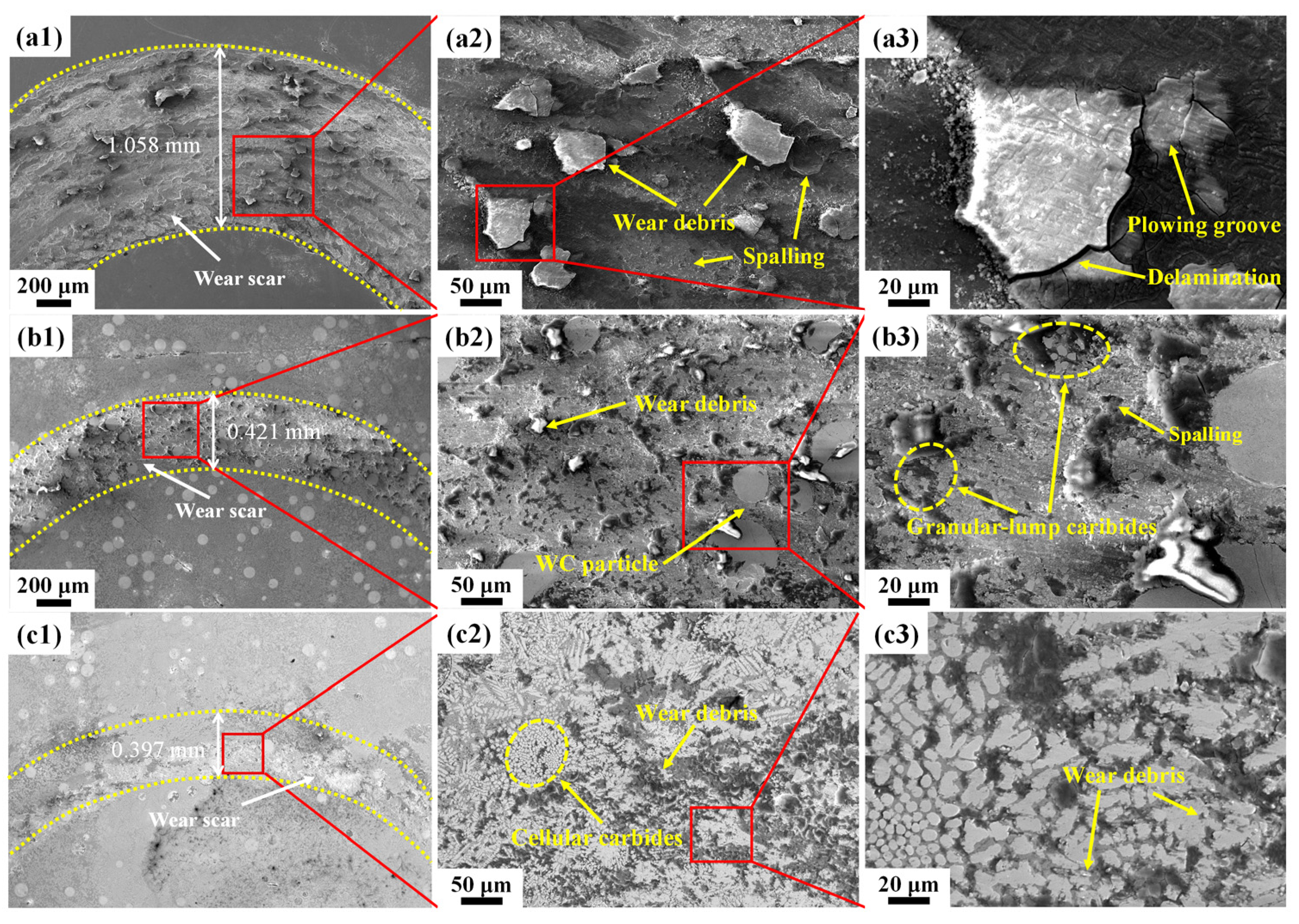
3.3.3. Tribological Properties

The friction and wear curves of the three coatings are shown in Figure 12a. The friction and wear curves of the three coatings can be divided into two stages: the rapid growth stage and the steady wear stage. In the initial stage, due to the flatness of the sample and the cold-welding effect of wear debris between friction pairs, the grind ball needed greater friction force to overcome the above negative factors. Therefore, the friction and wear coefficient increased significantly. After a period of running-in, as the cold-welding areas were cut off, the friction and wear coefficient decreased sharply, and all curves entered a relatively stable stage after 6 min. The mean coefficients of friction (COFs) for Coatings A, B and C are 0.605, 0.546 and 0.494, respectively. Therefore, the abrasion curve of Coating C is the most stable, and also has the smallest COF. In addition, the abrasion curve of Coating C is more stable than those of the other coatings and it was the first to enter the steady wear stage. This can be attributed to the more uniform distribution of WC particles and grain refinement induced by ultrasonic, as shown in Figure 4 and Figure 6.
In order to further study the wear mechanism of various coatings, the morphologies of worn surfaces were observed by SEM, as shown in Figure 13. The wear scar width decreases successively from 1.058 mm on Coating A to 0.397 mm on Coating C, which means the wear resistance of the coating was improved. For Coating A, which was prepared by IN718 alloy powder, large wear debris, obvious plowing grooves and spalling pits in the sliding direction were found (Figure 13a). The WC particles and precipitated carbides enhance the wear resistance of the coating. As shown in Figure 13(a2,a3), the WC particles and granular-lump carbides with high hardness can improve surface resistance to local plastic deformation and destruction capabilities. Compared with Coating A and Coating B, Coating C has the smallest wear debris, which can be attributed to the uniform distribution of WC particles and formation of fine dispersed carbides. Acoustic streaming and cavitation induced by ultrasonic promote the even particle distribution in the upper region of the coating and grain refinement. Coating C has excellent friction performance caused by precipitation and grain refinement strengthening.

4. Discussion

Numerous recent research works indicate that dendrite fragmentation and microstructure refinement in metal solidification processes with ultrasonic treatment are mainly ascribed to the cavitation effect of ultrasonic [21,35,36]. The cavitation effect is the result of the dynamic interaction between sound pressure and bubbles. Figure 14 shows the two-dimensional model for finite element simulation. The model is predigested to an integration of two semi-ellipses by gauging the cross-section of the single-track cladding layer.
When high-intensity ultrasonic is introduced into the molten pool, the tiny bubbles in liquid metal are subjected to periodic action of sound pressure. When there is a cavitation nucleus with initial radius R0 in the molten pool, the cavitation threshold of the molten pool in the form of sound pressure is expressed as [37]:
P B = P 0 P v + 2 3 3 [ ( 2 σ R 0 ) P 0 P v + 2 σ R 0 ] 1 2
where P0 = 101 kPa is the liquid static pressure, Pv = 0 kPa is the saturated steam pressure, σ = 1.5 N/m is the liquid surface tension coefficient of the IN718 alloy molten pool and R0 = 5 µm is the initial radius of the cavitation bubble. The corresponding cavitation threshold PB in liquid IN718 metal is 0.3 MPa, calculated by Equation (5). The ultrasonic input position is located at the bottom of the substrate, the same as in the experimental setup. The molten pool and the substrate are modelled separately with the pressure-acoustic, frequency-domain and solid mechanics modules in COMSOL Multiphysics software. In order to simplify the model, the influences of the WC particle’s distribution and dissolution on physical parameters such as liquid metal density and dynamic viscosity are ignored. The entire molten pool is assumed to be filled with the melting IN718 alloy to characterize the function of ultrasonic. The Y-axis sinusoidal displacement A(t) on the middle of the substrate’s bottom is set as
A ( t ) = A m sin ( 2 π f t )
where Am = 20 µm is the vibration amplitude and ω = 20 kHz is the ultrasonic frequency. A sound-soft boundary is applied to simulate the vapor–liquid interface at the top of the molten pool, and the acoustic impedance of the top boundary is nil. At the same time, an acoustic-structure boundary coupling model was used to calculate the actual distribution of sound pressure of the molten pool in this work and the results are shown in Figure 15.
Figure 15a shows the transient sound pressure distribution in the molten pool and the displacement of the substrate which was extracted from 1 µs to 6 µs in the first period of ultrasonic (50 µs). It is remarked that regions with the actual value of sound pressure surpassing the cavitation threshold (0.3 MPa) are mainly distributed in the middle and lower parts of the molten pool. Figure 15b shows the average, maximum and minimum sound pressures of the whole molten pool within ten ultrasonic cycles. The results show that the sound pressure in the molten pool gradually tends to be stable despite large amplitude oscillation with time, which is mainly caused by the attenuation effect associated with the propagation of sound waves in the fluid. In order to further investigate the expansion, contraction and collapse process of cavitation bubbles in the molten pool, the evolution law of individual cavitation bubbles under different sound pressure fields is analyzed based on the Rayleigh–Plesset model [38]:
R d 2 R d t 2 + 3 2 ( d R d t ) 2 = 1 ρ [ ( P 0 + 2 σ R 0 P v ) ( R 0 R ) 3 k 2 σ R 4 μ 1 R d R d t P 0 + P v + P m sin ( ω t ) ]
where R is the real-time radius of the cavitation bubble; t is time; k is the ratio of the specific heat at a constant pressure to specific heat at a constant volume of gas in the bubble, taking 4/3; and µ is the dynamic viscosity of molten IN718 alloy, taking 0.005 Pa·s. Additionally, Pmsin(ωt) is the acoustic pressure in the cladding pool substituted with the simulated values, as shown in Figure 15, to solve this differential equation.
The Rayleigh–Plesset equation is solved using the differential equation interface in COMSOL Multiphysics software, and the evolution law of the cavitation bubble under specific sound pressure amplitude, initial radius and ultrasonic frequency is calculated as shown in Figure 16. The horizontal coordinate is the ratio of time to ultrasound period and the vertical coordinate is the ratio of the real-time radius of the cavitation bubble to the initial radius, showing the variation of the cavitation bubble radius over ten ultrasound periods.
When the radius of cavitation bubbles and ultrasonic frequency are certain, the evolution law of the bubble’s radius with different sound pressures from 0.40 MPa to 0.90 MPa is shown in Figure 16a. The results indicate that only when the sound pressure in the molten pool is much higher than the cavitation threshold can the radius of cavitation bubbles vary significantly. The cavitation bubbles with various radii are invariably in the condition of moderate amplitude and nonlinear oscillation at an acoustic pressure of 0.8 MPa; some do not even collapse within ten sound pressure cycles, as shown in Figure 16b.
Based on the R–P equation to predict the effect of ultrasonic frequency on cavitation bubble radius, Figure 16c shows that under the sound pressure field with the sound pressure of 0.8 MPa and the initial radius of 5 µm, the collapse times of the cavitation bubbles at frequencies of 20 kHz, 21 kHz, 22 kHz, 23 kHz and 24 kHz are 3.85 T, 5.16 T, 0.87 T, 3.16 T and 3.90 T, respectively. Moreover, the maximum radii of the cavitation bubbles during dynamic evolution are 76.36, 53.57, 25.50, 58.62 and 63.88 times the initial radius, respectively. At an ultrasonic frequency of 20 kHz, the intensity of cavitation is guaranteed to include higher radius variation and moderate collapse time. Some experimental observations indicated that when the ultrasonic frequency increased to a certain value, no ultrasonic cavitation occurred or cavitation could not be detected, resulting in a more stable pressure value in the flow field [39]. The main reason for this anomaly is that at higher ultrasonic frequencies, the cavitation bubbles do not have enough time to expand and contract under the effect of alternating strong positive and negative pressures, and the difficulty of generating the cavitation effect increases. Therefore, low-frequency ultrasonic was used in this study.
In this study, the size of the molten pool formed by laser irradiation was approximately equivalent to the width of a single-track cladding layer, which is about 2.4 mm. According to the laser scanning speed (450 mm/min), the existence time of the molten pool was estimated to be about 0.32 s, which was long enough to cover the annihilation time of the cavitation bubbles (about 0.00005 s). Therefore, the solidification process of the molten pool can experience up to ~103 cavitation.
Based on the above cavitation simulation, the ultrasonic used in this experiment can generate the cavitation effect, and the cavitation intensity can be guaranteed. On the one hand, a large number of cavitation bubbles are generated and then swell up at the initial stage of ultrasonic cavitation; these bubbles absorb considerable heat from the liquid metal. Therefore, the overall undercooling degree of the molten pool increases, which is conducive to decreasing the grain size. On the other hand, acoustic streaming and microjets generated by the collapse of cavitation bubbles both promote the internal flow of melt as well as the uniform distribution of solute elements in the coating. The combined action of the above two factors refines the microstructure of the coating. Some laboratory observations using synchrotron radiation indicated that acoustic cavitation and acoustic streaming can break the growing dendrites into tiny fragments, and these fragments then act as the nucleus of heterogeneous nucleation [40,41].
The schematic illustration of grain refinement in the molten pool is shown in Figure 17. Under the action of a high-energy density laser, WC particles decompose and react with elements in the IN718 matrix to precipitate massive carbides with sharp edges and coarse structure, as shown Figure 17a,b. After introducing ultrasonic into the molten pool, acoustic cavitation and the acoustic streaming effect greatly improve thermal convection and mass transfer, which promote the decomposition of WC particles, and the size of carbides is refined, as shown in Figure 17c,d. Moreover, the tiny fragments from growing dendrites act as the nucleus of heterogeneous nucleation, which can result in the growth of equiaxed grains.
In short, the enhancements in mechanical properties (microhardness, residual stress and wear resistance) of IN718-WC composite coatings can be attributed to precipitation strengthening and microstructure refining induced by fine dispersed carbides.

5. Conclusions

IN718 coating, IN718-50 wt.% WC and IN718-50 wt.% WC (ultrasonic assistance) composite coatings were prepared by laser cladding. The influences of decomposition of WC particles and ultrasonic vibration on composition, microstructure evolution, microhardness, residual stress and tribological prosperities have been systematically analyzed. The following main conclusions can be drawn:
(1)
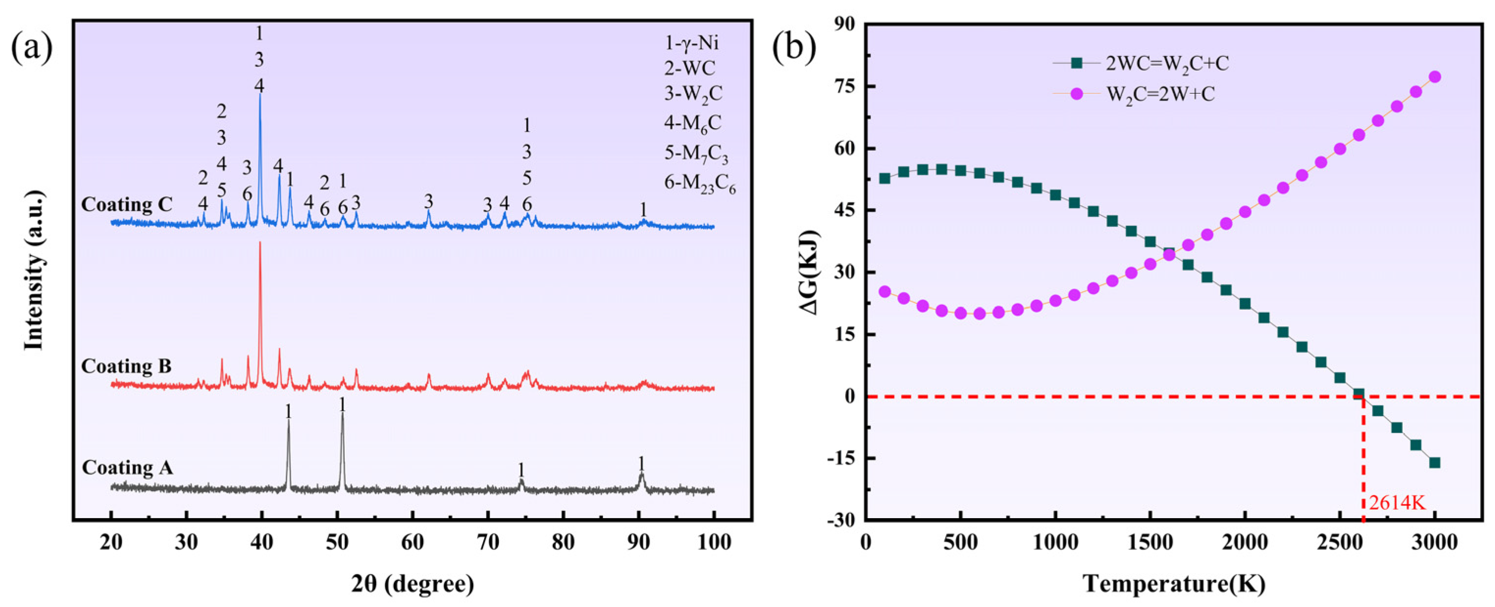
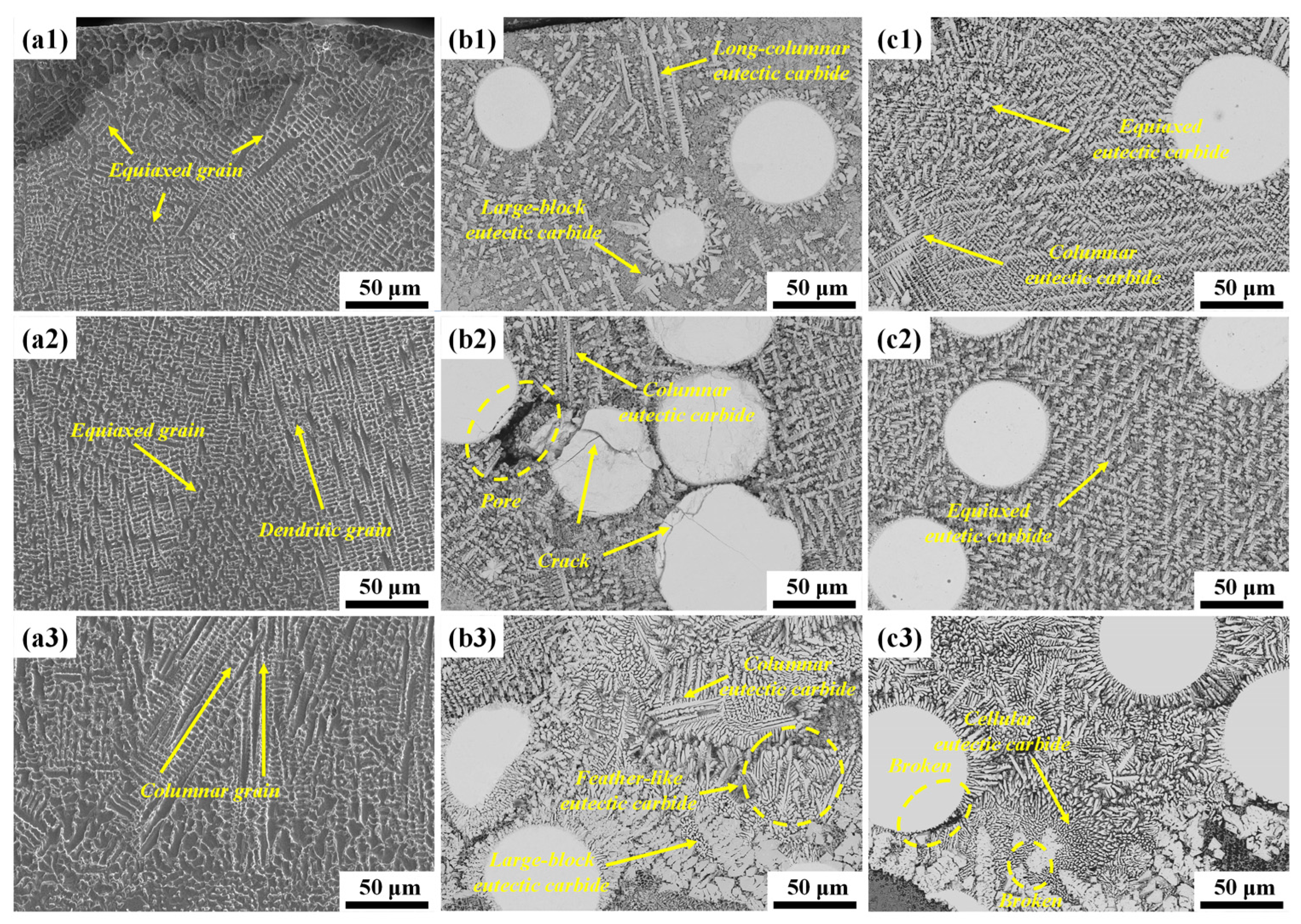
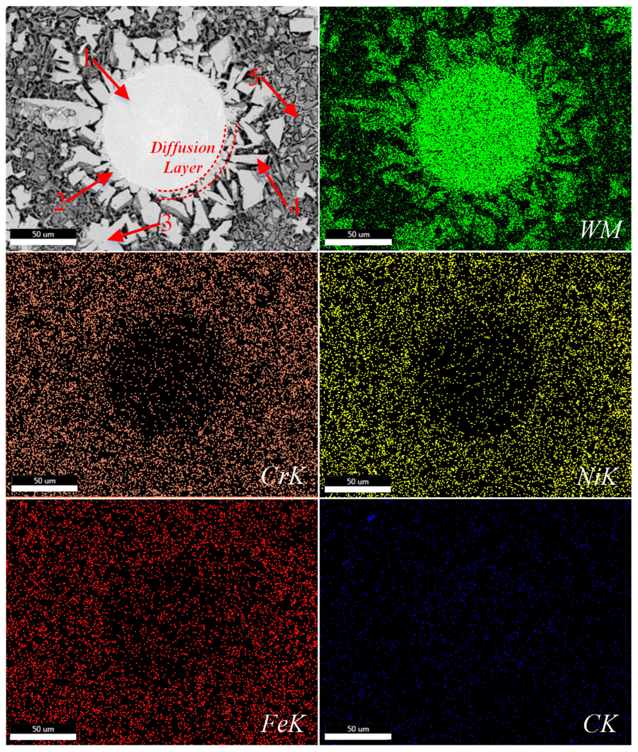
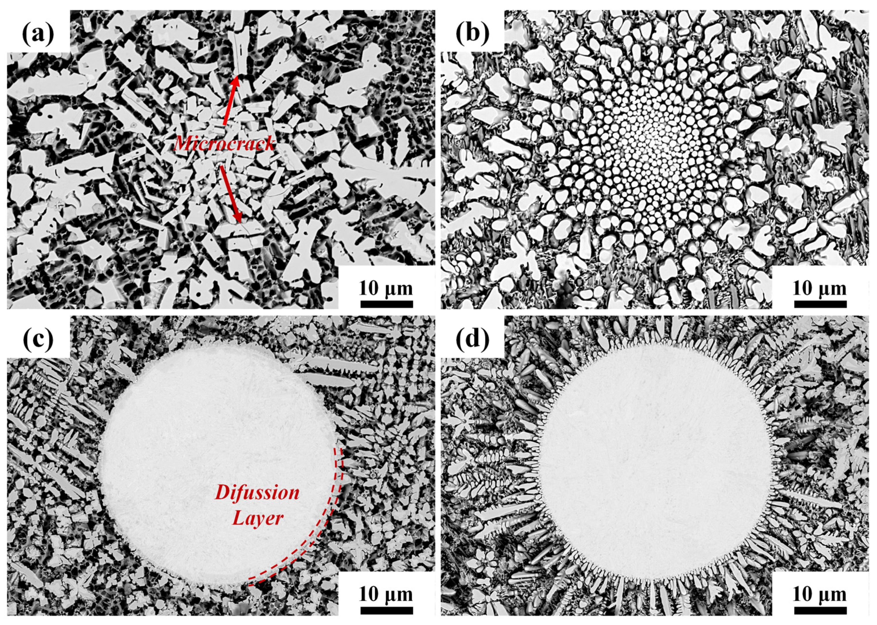
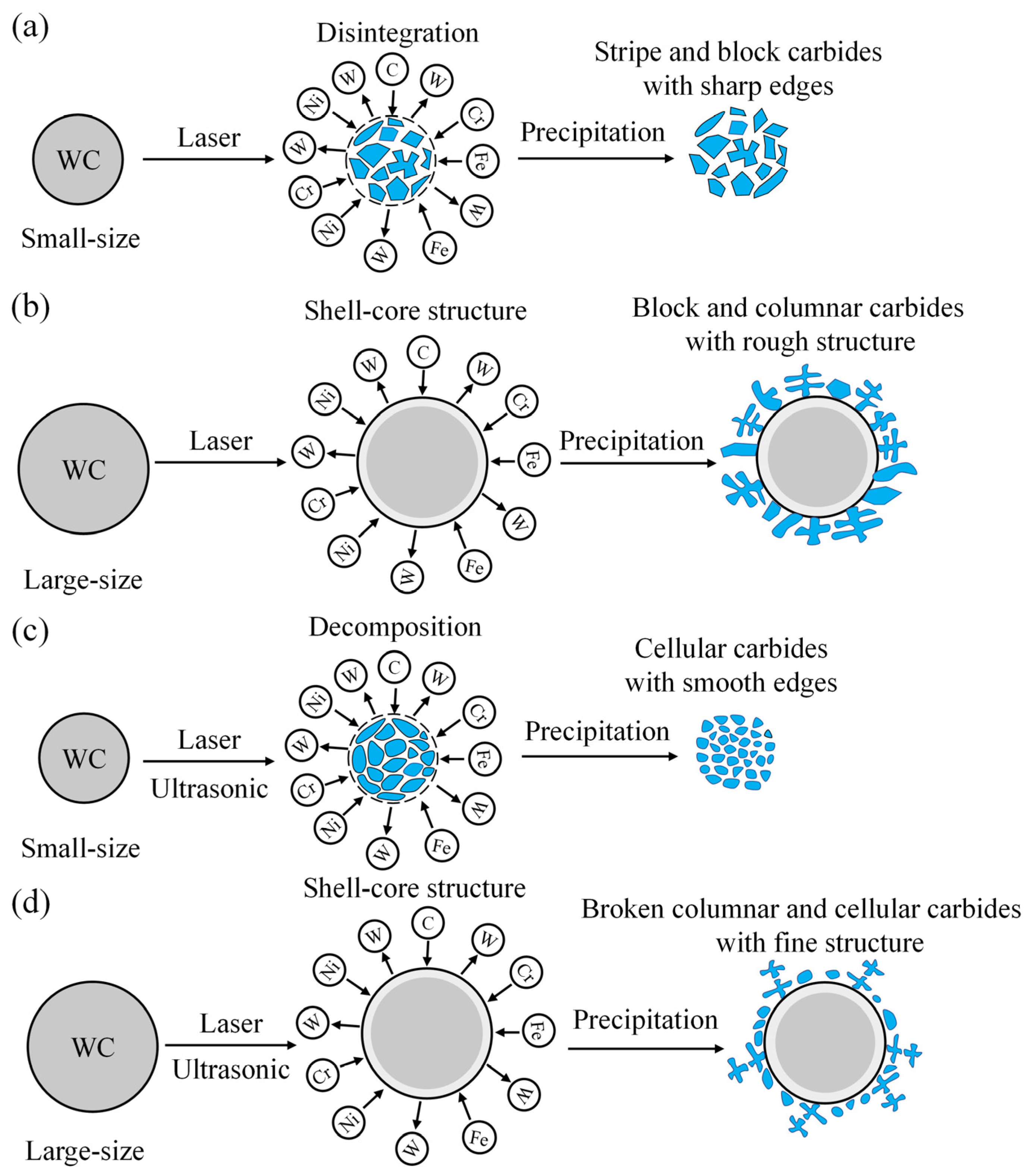
The main phase in laser cladding IN718 coating is the γ-Ni phase. With the addition of numerous WC particles, the phase compositions are converted into γ-Ni, WC, W2C, M6C (Fe3W3C and Fe3Mo3C), M7C3 (Cr7C3) and M23C6 (Cr23C6) due to considerable generation of precipitated carbides with various shapes and sizes.
(2)
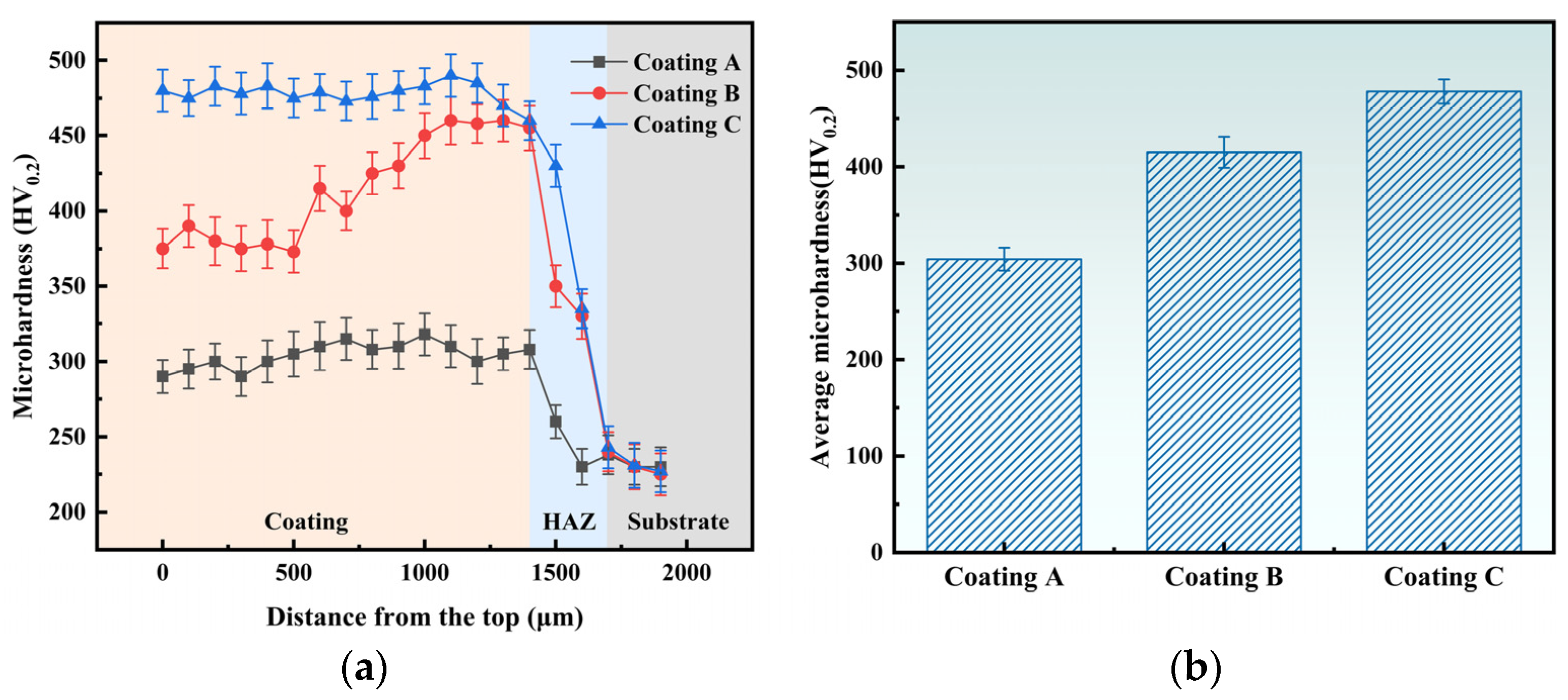
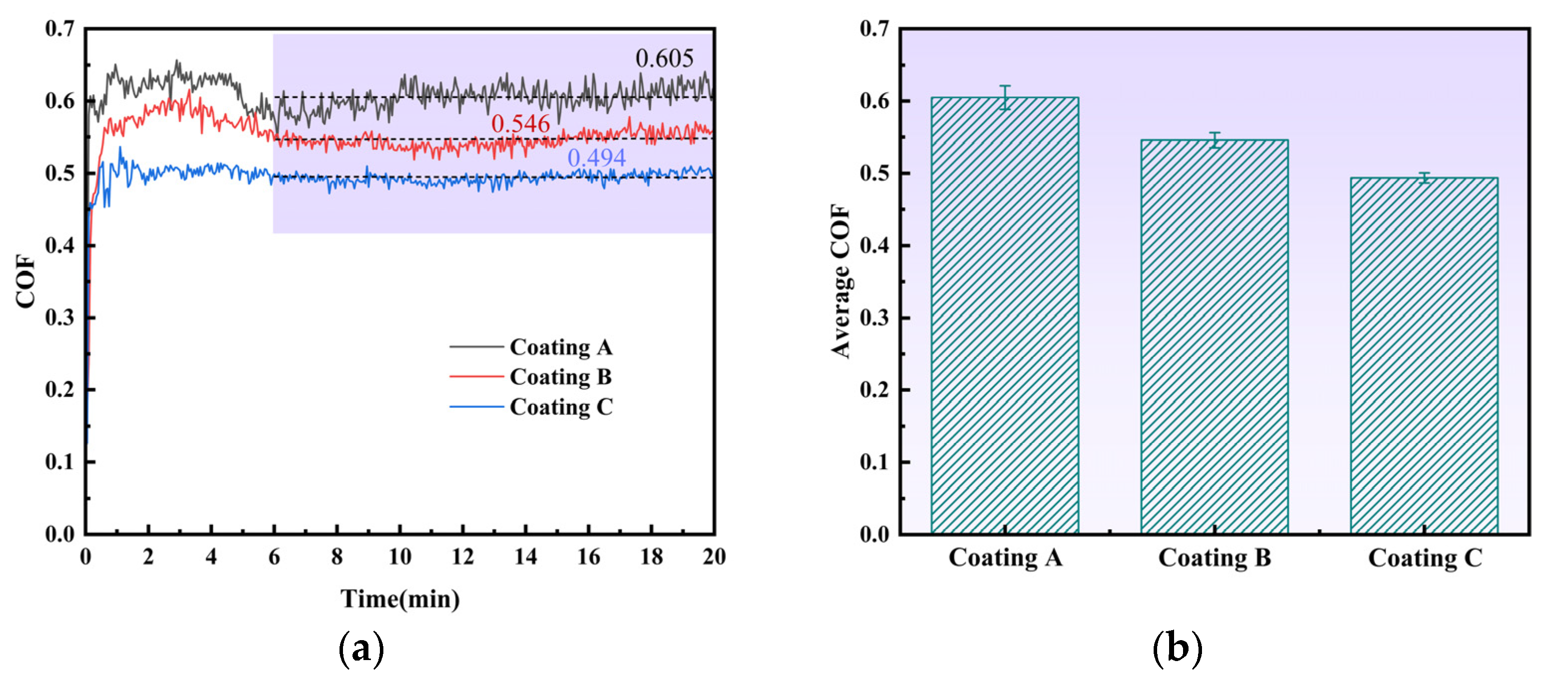
The decomposition of WC particles can greatly enhance microhardness and wear resistance of composite coatings. Meanwhile, acoustic streaming and cavitation can homogenize the distribution of WC particles and refine the microstructure. Therefore, the composite coating assisted by ultrasonic has the highest microhardness (478.15 HV0.2) and the lowest COF (0.494).
(3)
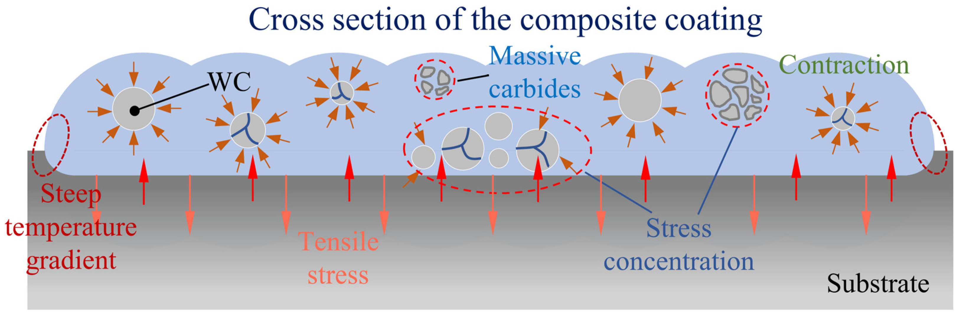
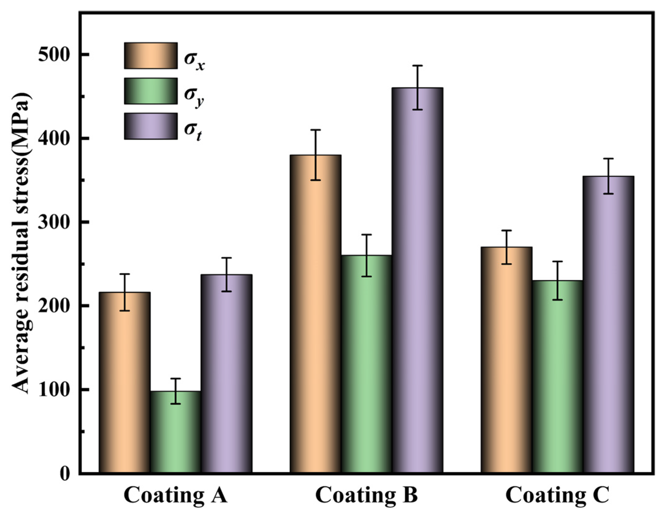
Massive particles and carbides can increase residual stress on the surfaces of coatings, while ultrasonic vibration can inhibit the formation of massive carbides with sharp edges. Thus, the resultant residual stress and the gap between σx and σy can be effectively decreased.
(4)
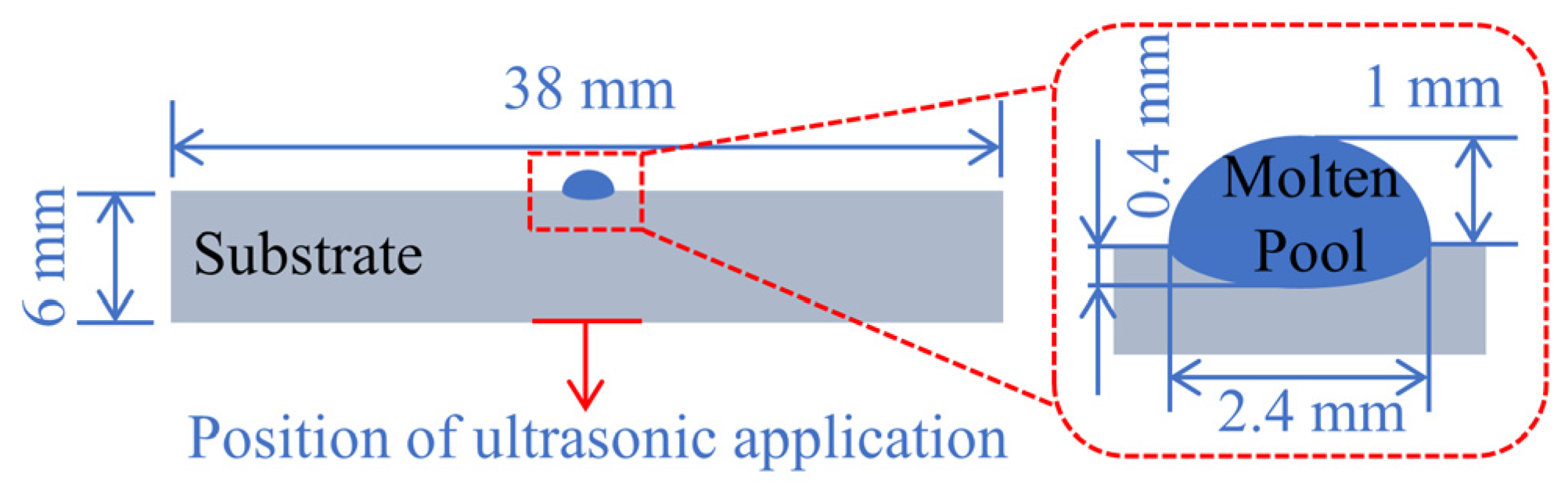
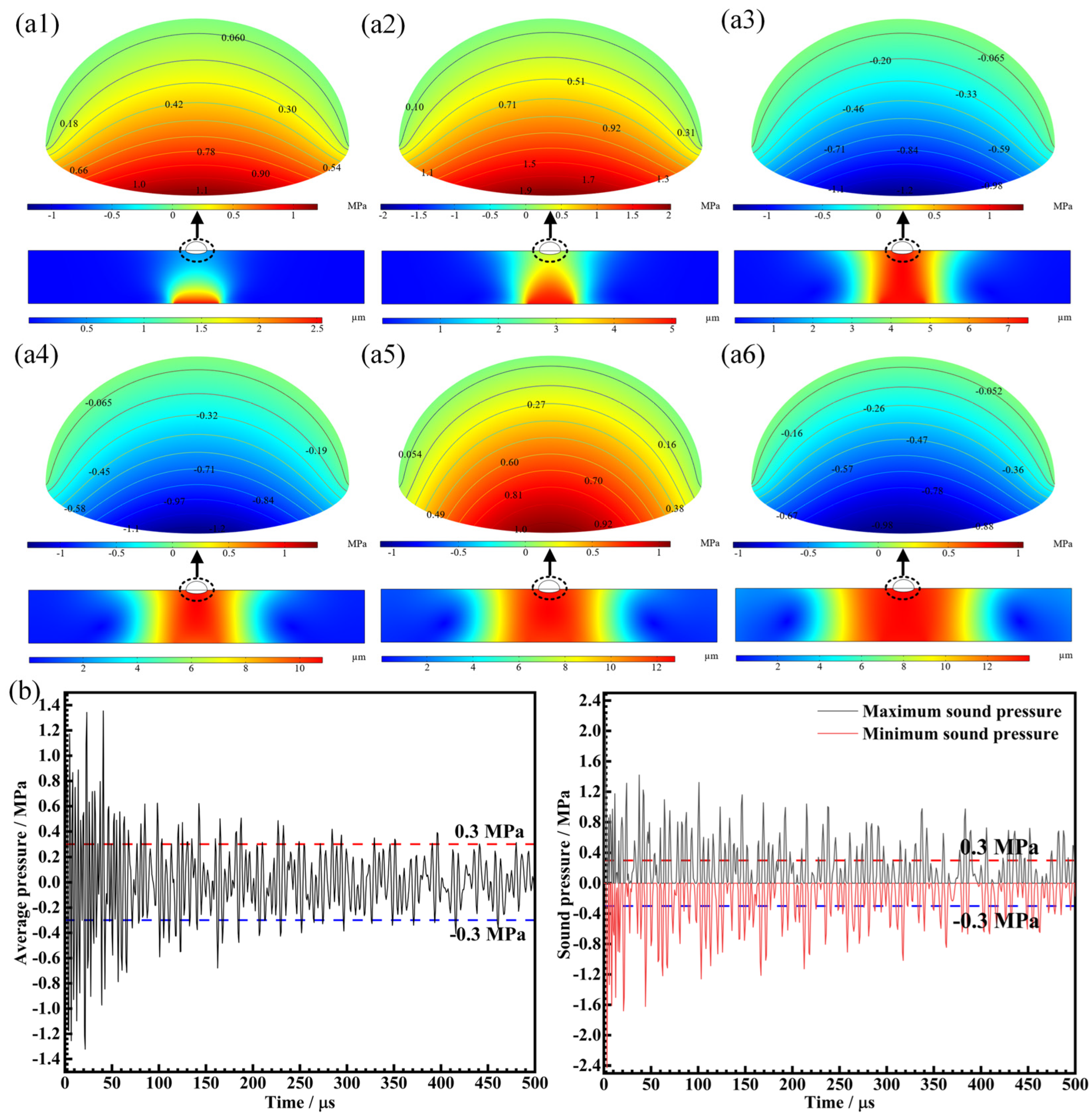
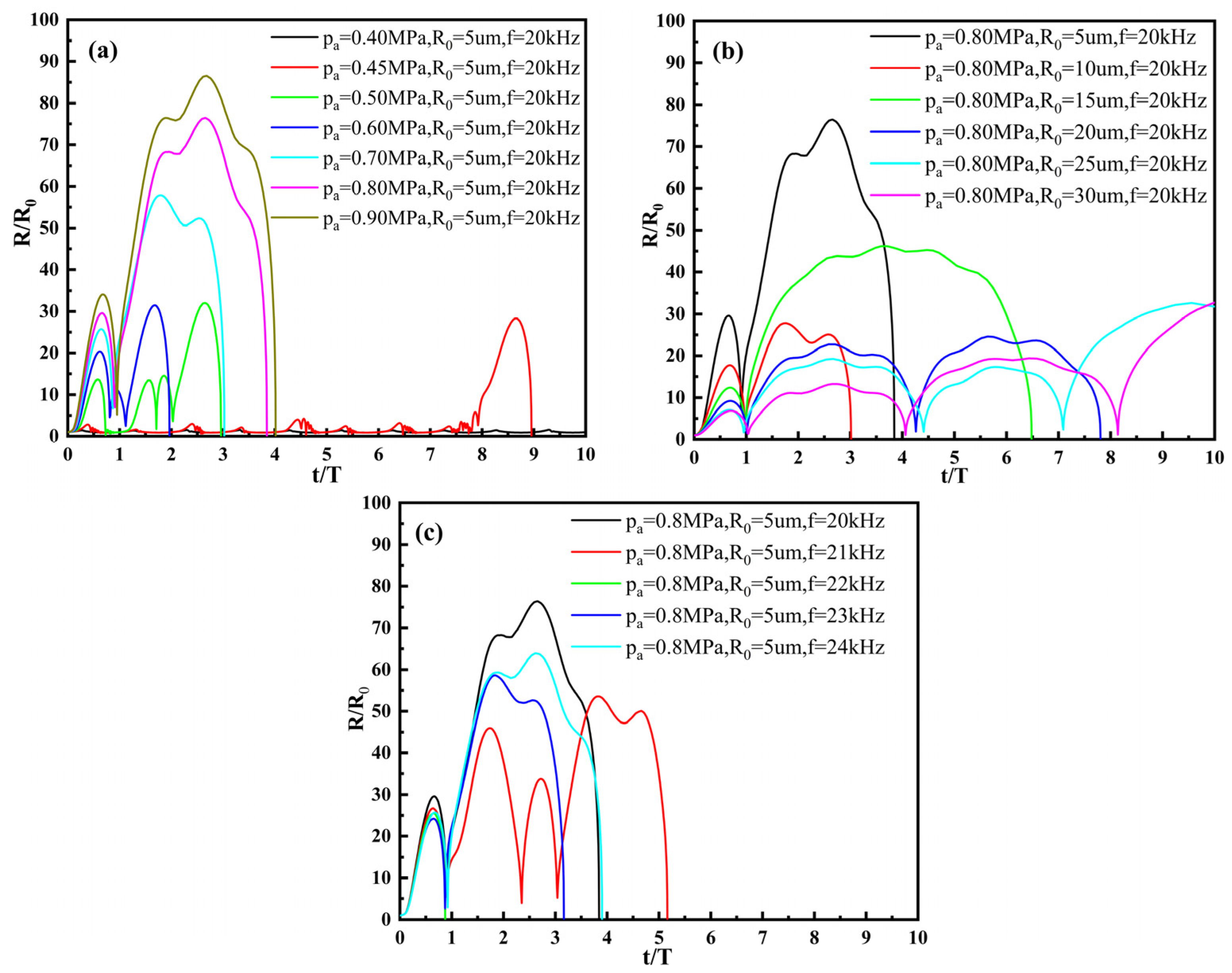
The cavitation effect is mainly concentrated at the bottom of the molten pool. The ultrasonic used in this work can guarantee the intensity of cavitation, including through higher radius variation and moderate collapse time.

Author Contributions

Conceptualization, J.Z.; methodology, J.Z.; validation, J.W. and T.Z.; formal analysis, T.Z. and P.L.; investigation, J.W.; resources, J.Z., X.M., H.Z. and S.H.; data curation, J.W.; writing—original draft preparation, J.W.; writing—review and editing, J.Z.; visualization, J.W. and P.L.; supervision, J.Z.; project administration, J.Z.; funding acquisition, J.Z., X.M., S.H. and H.Z. All authors have read and agreed to the published version of the manuscript.

Funding

This research was funded by the National Natural Science Foundation of China (grant number 51875265).

Institutional Review Board Statement

Not applicable.

Informed Consent Statement

Not applicable.

Data Availability Statement

Not applicable.

Conflicts of Interest

The authors declare no conflict of interest.

References

  1. Mandal, V.; Tripathi, P.; Kumar, A.; Singh, S.S.; Ramkumar, J. A study on selective laser melting (SLM) of TiC and B4C reinforced IN718 metal matrix composites (MMCs). J. Alloys Compd. 2022, 901, 163527. [Google Scholar] [CrossRef]
  2. Wang, T.; Zhu, L.; Song, H.; Wang, H. Effect of WC-17Co content on microstructure and properties of IN718 composites prepared by laser cladding. Opt. Laser Technol. 2022, 148, 107780. [Google Scholar] [CrossRef]
  3. Chen, T.; Deng, Z.; Liu, D.; Zhu, X.; Xiong, Y. Bioinert TiC ceramic coating prepared by laser cladding: Microstructures, wear resistance, and cytocompatibility of the coating. Surf. Coat. Technol. 2021, 423, 127635. [Google Scholar] [CrossRef]
  4. Lei, J.; Shi, C.; Zhou, S.; Gu, Z.; Zhang, L.-C. Enhanced corrosion and wear resistance properties of carbon fiber reinforced Ni-based composite coating by laser cladding. Surf. Coat. Technol. 2018, 334, 274–285. [Google Scholar] [CrossRef] [Green Version]
  5. Hu, Y.; Wang, L.; Yao, J.; Xia, H.; Li, J.; Liu, R. Effects of electromagnetic compound field on the escape behavior of pores in molten pool during laser cladding. Surf. Coat. Technol. 2020, 383, 125198. [Google Scholar] [CrossRef]
  6. Li, M.; Zhang, Q.; Han, B.; Song, L.; Cui, G.; Yang, J.; Li, J. Microstructure and property of Ni/WC/La2O3 coatings by ultrasonic vibration-assisted laser cladding treatment. Opt. Lasers Eng. 2020, 125, 105848. [Google Scholar] [CrossRef]
  7. Xu, S.; Cai, Q.; Li, G.; Lu, X.; Zhu, X. Effect of scanning speed on microstructure and properties of TiC/Ni60 composite coatings on Ti6Al4V alloy by laser cladding. Opt. Laser Technol. 2022, 154, 108309. [Google Scholar] [CrossRef]
  8. Jiang, C.; Zhang, J.; Chen, Y.; Hou, Z.; Zhao, Q.; Li, Y.; Zhu, L.; Zhang, F.; Zhao, Y. On enhancing wear resistance of titanium alloys by laser cladded WC-Co composite coatings. Int. J. Refract. Met. Hard Mater. 2022, 107, 105902. [Google Scholar] [CrossRef]
  9. Chen, Y.; Zhou, J.; Li, P.; Huo, K.; Meng, X. Effect of Electromagnetic Field on Wear Resistance of Fe901/Al2O3 Metal Matrix Composite Coating Prepared by Laser Cladding. Materials 2022, 15, 1531. [Google Scholar] [CrossRef]
  10. Obadele, B.A.; Andrews, A.; Olubambi, P.A.; Mathew, M.T.; Pityana, S. Effect of ZrO 2 addition on the dry sliding wear behavior of laser clad Ti6Al4V alloy. Wear 2015, 328–329, 295–300. [Google Scholar] [CrossRef]
  11. Jing, P.; Wang, H.; Chen, W.; Chen, L.; Yin, H.; Wu, H.; Li, D. Effect of Ti addition on microstructure and tribological properties of laser cladding Ni35/WC coating in an oxygen-free environment. Surf. Coat. Technol. 2022, 440, 128480. [Google Scholar] [CrossRef]
  12. Wang, X.; Zhou, S.; Dai, X.; Lei, J.; Guo, J.; Gu, Z.; Wang, T. Evaluation and mechanisms on heat damage of WC particles in Ni60/WC composite coatings by laser induction hybrid cladding. Int. J. Refract. Met. Hard Mater. 2017, 64, 234–241. [Google Scholar] [CrossRef]
  13. Li, G.J.; Li, J.; Luo, X. Effects of high temperature treatment on microstructure and mechanical properties of laser-clad NiCrBSi/WC coatings on titanium alloy substrate. Mater. Charact. 2014, 98, 83–92. [Google Scholar] [CrossRef]
  14. Xia, Y.; Chen, H.; Liang, X.; Lei, J. Circular oscillating laser melting deposition of nickel-based superalloy reinforced by WC: Microstructure, wear resistance and electrochemical properties. J. Manuf. Process. 2021, 68, 1694–1704. [Google Scholar] [CrossRef]
  15. Shen, X.; He, X.; Gao, L.; Su, G.; Xu, C.; Xu, N. Study on crack behavior of laser cladding ceramic-metal composite coating with high content of WC. Ceram. Int. 2022, 48, 17460–17470. [Google Scholar] [CrossRef]
  16. Wang, L.; Yao, J.; Hu, Y.; Zhang, Q.; Sun, Z.; Liu, R. Influence of electric-magnetic compound field on the WC particles distribution in laser melt injection. Surf. Coat. Technol. 2017, 315, 32–43. [Google Scholar] [CrossRef]
  17. Zhang, N.; Liu, W.; Deng, D.; Tang, Z.; Liu, X.; Yan, Z.; Zhang, H. Effect of electric-magnetic compound field on the pore distribution in laser cladding process. Opt. Laser Technol. 2018, 108, 247–254. [Google Scholar] [CrossRef]
  18. Huo, K.; Zhou, J.; Dai, F.; Xu, J. Particle distribution and microstructure of IN718/WC composite coating fabricated by electromagnetic compound field-assisted laser cladding. Appl. Surf. Sci. 2021, 545, 149078. [Google Scholar] [CrossRef]
  19. Han, X.; Li, C.; Yang, Y.; Gao, X.; Gao, H. Experimental research on the influence of ultrasonic vibrations on the laser cladding process of a disc laser. Surf. Coat. Technol. 2021, 406, 126750. [Google Scholar] [CrossRef]
  20. Zhang, T.; Zhou, J.; Lv, J.; Meng, X.; Li, P.; Huang, S. A novel hybrid ultrasonic and electromagnetic field assisted laser cladding: Experimental study and synergistic effects. J. Mater. Process. Technol. 2022, 307, 117658. [Google Scholar] [CrossRef]
  21. Zhu, L.; Yang, Z.; Xin, B.; Wang, S.; Meng, G.; Ning, J.; Xue, P. Microstructure and mechanical properties of parts formed by ultrasonic vibration-assisted laser cladding of Inconel Surf. Coat. Technol. 2021, 410, 126964. [Google Scholar] [CrossRef]
  22. Fan, Q.; Chen, C.; Fan, C.; Liu, Z.; Cai, X.; Lin, S.; Yang, C. Ultrasonic induces grain refinement in gas tungsten arc cladding AlCoCrFeNi high-entropy alloy coatings. Mater. Sci. Eng. A 2021, 821, 141607. [Google Scholar] [CrossRef]
  23. Xu, J.; Zhou, J.; Tan, W.; Huang, S.; Wang, S.; He, W. Ultrasonic vibration on wear property of laser cladding Fe-based coating. Surf. Eng. 2020, 36, 1261–1269. [Google Scholar] [CrossRef]
  24. Nerz, J.; Kushner, B.; Rotolico, A. Microstructural evaluation of tungsten carbide-cobalt coatings. J. Therm. Spray Technol. 1992, 1, 147–152. [Google Scholar] [CrossRef]
  25. Sadhu, A.; Choudhary, A.; Sarkar, S.; Nair, A.M.; Nayak, P.; Pawar, S.D.; Muvvala, G.; Pal, S.K.; Nath, A.K. A study on the influence of substrate pre-heating on mitigation of cracks in direct metal laser deposition of NiCrSiBC-60%WC ceramic coating on Inconel Surf. Coat. Technol. 2020, 389, 125646. [Google Scholar] [CrossRef]
  26. Gan, Z.; Yu, G.; He, X.; Li, S. Numerical simulation of thermal behavior and multicomponent mass transfer in direct laser deposition of Co-base alloy on steel. Int. J. Heat Mass Transf. 2017, 104, 28–38. [Google Scholar] [CrossRef] [Green Version]
  27. Wang, Q.; Li, Q.; Zhang, L.; Chen, D.X.; Jin, H.; Li, J.D.; Zhang, J.W.; Ban, C.Y. Microstructure and properties of Ni-WC gradient composite coating prepared by laser cladding. Ceram. Int. 2022, 48, 7905–7917. [Google Scholar] [CrossRef]
  28. Li, W.; Di, R.; Yuan, R.; Song, H.; Lei, J. Microstructure, wear resistance and electrochemical properties of spherical/non-spherical WC reinforced Inconel 625 superalloy by laser melting deposition. J. Manuf. Process. 2022, 74, 413–422. [Google Scholar] [CrossRef]
  29. Gan, Z.; Yu, G.; He, X.; Li, S. Surface-active element transport and its effect on liquid metal flow in laser-assisted additive manufacturing. Int. Commun. Heat Mass Transf. 2017, 86, 206–214. [Google Scholar] [CrossRef] [Green Version]
  30. Lippold, J.C. Welding Metallurgy and Weldability; John Wiley & Sons: Hoboken, NJ, USA, 2014. [Google Scholar]
  31. Abioye, T.E.; Folkes, J.; Clare, A.T.; McCartney, D.G. Concurrent Inconel 625 wire and WC powder laser cladding: Process stability and microstructural characterisation. Surf. Eng. 2013, 29, 647–653. [Google Scholar] [CrossRef]
  32. Tan, H.; Luo, Z.; Li, Y.; Yan, F.; Duan, R. Microstructure and wear resistance of Al2O3–M7C3/Fe composite coatings produced by laser controlled reactive synthesis. Opt. Laser Technol. 2015, 68, 11–17. [Google Scholar] [CrossRef]
  33. Zhou, S.; Zeng, X.; Hu, Q.; Huang, Y. Analysis of crack behavior for Ni-based WC composite coatings by laser cladding and crack-free realization. Appl. Surf. Sci. 2008, 255, 1646–1653. [Google Scholar] [CrossRef]
  34. Tian, J.; Xu, P.; Liu, Q. Effects of stress-induced solid phase transformations on residual stress in laser cladding a Fe-Mn-Si-Cr-Ni alloy coating. Mater. Des. 2020, 193, 108824. [Google Scholar] [CrossRef]
  35. Ji, F.; Qin, X.; Hu, Z.; Xiong, X.; Ni, M.; Wu, M. Influence of ultrasonic vibration on molten pool behavior and deposition layer forming morphology for wire and arc additive manufacturing. Int. Commun. Heat Mass Transf. 2022, 130, 105789. [Google Scholar] [CrossRef]
  36. Yuan, D.; Shao, S.; Guo, C.; Jiang, F.; Wang, J. Grain refining of Ti-6Al-4V alloy fabricated by laser and wire additive manufacturing assisted with ultrasonic vibration. Ultrason. Sonochem. 2021, 73, 105472. [Google Scholar] [CrossRef]
  37. Jamshidi, R.; Brenner, G. Dissipation of ultrasonic wave propagation in bubbly liquids considering the effect of compressibility to the first order of acoustical Mach number. Ultrasonics 2013, 53, 842–848. [Google Scholar] [CrossRef]
  38. Geng, L.; Chen, J.; Escaler, X. Improvement of cavitation mass transfer modeling by including Rayleigh–Plesset equation second order term. Eur. J. Mech.—B/Fluids 2020, 84, 313–324. [Google Scholar] [CrossRef]
  39. Lv, T.; Li, Y. Simulation of Ultrasonic Flow Polishing inside the Mold Cavity. Front. Manuf. Eng. 2015, 3, 20–24. [Google Scholar] [CrossRef]
  40. Wang, F.; Eskin, D.; Mi, J.; Wang, C.; Koe, B.; King, A.; Reinhard, C.; Connolley, T. A synchrotron X-radiography study of the fragmentation and refinement of primary intermetallic particles in an Al-35 Cu alloy induced by ultrasonic melt processing. Acta Mater. 2017, 141, 142–153. [Google Scholar] [CrossRef]
  41. Wang, B.; Tan, D.; Lee, T.L.; Khong, J.C.; Wang, F.; Eskin, D.; Connolley, T.; Fezzaa, K.; Mi, J. Ultrafast synchrotron X-ray imaging studies of microstructure fragmentation in solidification under ultrasound. Acta Mater. 2018, 144, 505–515. [Google Scholar] [CrossRef]
Figure 1. SEM images of powders. (a) Spherical IN718; (b) spherical WC.
Coatings 13 00151 g001
Figure 2. Setup for laser cladding with ultrasonic assistance. (a) Overall layout diagram; (b) schematic diagram of ultrasonic-assisted laser cladding processing system.
Coatings 13 00151 g002
Figure 3. (a) Top view of the laser cladding coating; (b) laser scanning path; (c) residual stress testing points.
Coatings 13 00151 g003
Figure 4. Cross-sectional morphologies of different coatings: (a) Coating A; (b) Coating B; (c) Coating C; 1 and 2 represent partial enlarged images of the top and bottom regions respectively.
Coatings 13 00151 g004
Figure 5. (a) XRD patterns of the three coatings; (b) relationship between temperature and free enthalpy.
Coatings 13 00151 g005
Figure 6. Typical microstructure on cross-section. (a1a3), (b1b3) and (c1c3) are the cross-sectional morphologies of Coating A, Coating B and Coating C, respectively. 1, 2 and 3 represent the top region, middle region and bottom region, respectively.
Coatings 13 00151 g006
Figure 7. EDS map scanning results of typical microstructure in composite coatings.
Coatings 13 00151 g007
Figure 8. Thermal decomposition characteristics of WC particles during laser cladding process with and without ultrasonic: (a,b) disintegration–diffusion type for WC particles with small size; (c,d) dissolution–diffusion type for WC particles with large size.
Coatings 13 00151 g008
Figure 9. (a) Microhardness of different coatings along the depth direction; (b) average hardness of cladding layers of different coatings.
Coatings 13 00151 g009
Figure 10. Mechanism of residual stress generation during laser cladding.
Coatings 13 00151 g010
Figure 11. Average residual stress of different coatings.
Coatings 13 00151 g011
Figure 12. (a) Friction and wear curves of different coatings; (b) average COF.
Coatings 13 00151 g012
Figure 13. Worn surface morphology of different coatings. (a1a3) Coating A; (b1b3) Coating B; (c1c3) Coating C.
Coatings 13 00151 g013
Figure 14. Numerical simulation model for ultrasonic effect.
Coatings 13 00151 g014
Figure 15. Simulation results of sound pressure in the molten pool: (a) sound pressure and vibration amplitude at 1 us to 6 us with 1 us time interval; (b) average, maximum and minimum sound pressures in the molten pool; 1–6 represents each microsecond from 1 us to 6 us.
Coatings 13 00151 g015
Figure 16. Influence of characteristic parameters on cavitation process. (a) Ultrasonic amplitude; (b) initial radius; (c) ultrasonic frequency.
Coatings 13 00151 g016
Figure 17. A schematic of grain refinement including small and large size WC particles in laser cladding: (a,b) without ultrasonic vibration; (c,d) with ultrasonic vibration.
Coatings 13 00151 g017
Table 1. Chemical composition of bonding metal IN718 alloy powder (wt.%).
ElementsNiCrNbMoAlSiTiFe
wt.%52.319.015.073.060.570.351.00Bal.
Table 2. The process parameters used in preparation of coatings.
Laser CladdingValueUltrasonic VibrationValue
Laser power (w)1300Ultrasonic power (w)300
Scanning speed (mm/min)450Amplitude (µm)20
Power feeding rate (g/min)16Angular frequency (kHz)20
Overlapping ration (%)50Wavelength (mm)1.7
Table 3. Physical properties of bonding metal IN718 alloy and WC particles.
MaterialsDensityExpansion CoefficientElastic ModulusMelting Point
g cm−310−6 K−1GpaK
IN7188.2411.8–18.7199.9–2401523
WC16.56.5–7.4650–7102798
Table 4. Chemical compositions of different phases in the composite coating.
PointPhaseComposition (wt.%)
WCNiFeCrMoNb
1WC78.6310.131.622.350.960.096.22
2W2C75.656.561.051.640.700.1814.21
3Block carbide49.109.6515.256.949.231.038.79
4Strip carbide42.216.5411.414.4911.641.3222.39
5Ni matrix12.352.145.8517.5815.250.766.11
Disclaimer/Publisher’s Note: The statements, opinions and data contained in all publications are solely those of the individual author(s) and contributor(s) and not of MDPI and/or the editor(s). MDPI and/or the editor(s) disclaim responsibility for any injury to people or property resulting from any ideas, methods, instructions or products referred to in the content.

