Article

Copper-Coated Graphite Felt as Current Collector for Li-Ion Batteries

by
Konstantin Pushnitsa
,
Alexandra Kosenko
*,
Vladislav Chernyavsky
,
Alexander A. Pavlovskii
,
Pavel Novikov
and
Anatoliy A. Popovich
Institute of Machinery, Materials and Transport, Peter the Great Saint Petersburg Polytechnic University, Politechnicheskaya ul. 29, 195251 Saint Petersburg, Russia
*
Author to whom correspondence should be addressed.
Coatings 2022, 12(9), 1321; https://doi.org/10.3390/coatings12091321
Submission received: 29 July 2022 / Revised: 26 August 2022 / Accepted: 7 September 2022 / Published: 10 September 2022

Abstract

:
Lithium-ion batteries (LIBs) undoubtedly are considered a viable option to meet the ever-increasing demands for portable consumer electronic devices and electric vehicles. To meet this requirement, intensive research is being conducted on increasing the volumetric and gravimetric energy density of LIBs as well as developing high-capacity electrode materials for LIB. In this study, a novel copper-coated graphite felt as a current collector is proposed for use as a constituent of LIB. Different type of Cu-coated graphite felt electrodes were synthesized. They were characterized by X-ray Diffractometer (XRD). To test its electrochemical performance Electrochemical Impedance Spectroscopy (EIS) and cyclic voltammetry (CVA) techniques were used. Materials with a specific capacity of up to 473 mAh∙g−1 were obtained. It was found that the nature of the capacity gain of carbon felt electrodes differs from that of graphite due to a different crystal structure. The use of a copper coating reduces the charge transfer resistance and increases the capacity of the material. Therefore, such new type of anode materials may be successfully used in LIBs.

1. Introduction

Among the different types of rechargeable batteries (e.g., nickel–cadmium, nickel–metal hydride, and lead-acid), Li-ion batteries (LIBs) have made significant progress since their first commercial implementation in June 1991 [1] by Sony Corporation. Nowadays, LIBs prevail in the worldwide battery market of consumer electronic devices and have been widely recognized as an ideal flexible energy storage medium [2,3], because of their high volumetric energy density, lightweight design, environmental friendliness, and long cycle life.
The ever-growing demand for consumer electronics, such as power banks, mobile phones, laptops, digital cameras, tablets, etc., required by today’s information-rich, mobile society [4] as well as the electrification of the automotive sector has led to a significant increase in the demand for LIBs [5]. Presently, LIBs have become a key component of portable, telecommunication, medical, computing, automotive, and entertainment equipment [6]. They have also shown outstanding promise for grid-scale energy storage systems. In electric vehicles (EV) and hybrid electric vehicles (HEV), lithium-ion batteries are significantly preferred over other types of batteries due to their enormous performance and long shelf life [7].
Undoubtedly, LIBs are considered a viable option to meet the ever-increasing demands for portable consumer electronic devices and EVs. To meet this requirement, intensive research is being conducted on increasing the volumetric and gravimetric energy density of LIBs [8] as well as developing high-capacity electrode materials for LIBs.
A relatively small theoretical capacity of graphite (372 mAh∙g−1 [9,10]) which is now the most widely used anode in LIBs greatly limits its extensive application [11]. Therefore, to boost the LIB’s performance, alternative promising and high theoretical capacity anode materials are required for the replacement of the currently used graphite. It’s a key issue to meet the rising demand for energy storage systems in the coming years.
In recent years, extensive researches have focused on using carbon-based fibers (CFs) as negative electrodes due to their good mechanical properties, flexibility, high electrical conductivity, and ability to intercalate lithium ions [12,13,14,15,16,17]. CFs are considered as long (generally > 1 mm), self-standing tows fibers with carbon as the basic component. Carbon fibers are seen to be a reasonably good material for structural batteries because they have a high electrical conductivity (up to 2 × 10⁴ Ω·cm−1 [18]) in the axial direction of the fiber. For this reason, there is no need to use current collectors or any conductive materials in the negative electrode in a structural battery.
Compared with conventional electrodes, CF-based yarn and fabric electrodes have many remarkable properties that make them an attractive option for electrical energy storage devices. One of the main reasons why researchers are devoting significant attention to CFs is that it provides fast charge (electrons or holes) transport to metal ions and active materials thanks to their continuous conductive network. In addition, their macroporous structure provides good ion diffusion kinetics and excellent electrolyte infiltration. Moreover, CFs can be used as flexible, lightweight, free-standing, and even structural electrodes without using a conductive agent or polymer binder for different new applications.
The specific capacity of traditional CMFs ranges between 200−300 mAh∙g−1 [6]. Despite the higher capacity of natural graphite (it’s theoretical/practical capacity: 372/~360 mAh∙g−1), CFs surpass it in terms of electrode capacity and electrode flexibility owing to their reasonably good mechanical and electrical properties which allow them to be directly used as anode materials without conductive agents and a binder.
It is worth mentioning that such a multi-functional, carbon fiber-based material as graphite felt (GF) which is produced by graphitization of CF is also extensively used as current collectors for flexible electrodes of electrochemical energy storage devices. It’s three-dimensional (3D) porous structure with high specific surface area [19,20] makes it an excellent choice for a wide range of energy and environmental applications. GF has received a lot of attention recently because of its reasonable electrical conductivity and mechanical flexibility as well as excellent corrosion resistance, reasonable cost, and high porosity and electrochemical stability [21,22]. Therefore, carbon materials like graphite felts have been widely tested as electrodes for various applications that include Li-ion batteries [23], vanadium redox flow batteries [24,25], microbial fuel cells [26,27], supercapacitors [28,29], biofuel cells [30,31], electro-Fenton process [32,33,34], and so forth.
However, the inherent hydrophobicity of pristine graphite felt leads to the low performance of GF-based electrochemical energy storage devices and its poor electrochemical activity in an aqueous solution [35]. In order to overcome the unsatisfactory electrochemical activity of the pristine GF, it’s necessary to modify its surface from hydrophobic to hydrophilic properties. At the same time, the GF should be maintained its own native high electrical conductivity in the process of such modification.
Diverse methods for modifying the GF surface at various conditions, such as nitrogenization treatment [36], plasma treatment [37], thermal treatment [38,39], carbon nanomaterials-based modification [40], chemical treatment [41,42], nanostructural metals [43], and metal oxides [44,45] decorating have been successfully developed and used. A further promising solution to modify the GF surface is the coating of graphite felts with metals by electroplating.
Electroplating is an easy way for the surface modification of CF. It avoids mechanical damage to the fibers. Among other surface modification strategies, electroplating is the least expensive technology. Copper is the metal of choice for most metallic coating for carbon fibers owing to it is non-reactive with carbon, it has good thermal and electrical conductivity, and moreover, interfacial phenomena, such as the intermetallics crystallizations, are negligible [46]. Furthermore, the thickness of the metal coating produced during the plating changes with the processing time and unlike, for example, the coating with physical vapor deposition (PVD), it’s easy to control.
Overall, GF-based electrodes have been the subject of several reviews related to environmental and energy topics. However, the majority of these reviews are devoted only to redox flow batteries and wastewater treatment by electrochemical advanced oxidation processes.
In the present work, we present several structural negative electrodes consisting of copper-modified GFs for LIBs with CR2032 coil-type cells. To the best of our knowledge, this is the first comprehensive report for LIBs in which we compare and discuss the electrochemical characteristics of various GF-based anode materials, such as the pristine GF, graphite-coated GF, copper-coated GF, and GF coated with copper and graphite simultaneously. The composition of the GF-based electrodes and their morphology have been characterized. Electrochemical characterization was carried out to test rate performance, capacity, and the presence of side reactions.
The findings demonstrated that a copper-modified current collector based on graphite felt increases LIB capacity up to 450 mAh∙g−1 and can be used to meet the rising demand for energy storage systems in the coming years. Therefore, we suggest using graphite felt coated with copper as alternative promising and high theoretical capacity anode material for LIBs to replace the currently used graphite anode materials with a relatively small specific capacity.

2. Materials and Methods

2.1. Synthesis of Cu-Coated Graphite Felt Electrode

To create a copper-coated current collector based on graphite felt, commercially available graphite felt was used (supplier ZLWMQMD 001 Store, Guangzhou, China). Commercially available synthetic graphite (artificial graphite powder) (supplier GELON LIB GROUP, Shandong, China) was used as the active material. Arkema’s PVDF of the Kynar brand and black carbon Carbon Black brand of the Super P company were used as a binder and conductive additive, respectively, during smearing. N-methyl-2-pyrrolidone (NMP) was used as a solvent for the preparation of a suspension. These materials were not subjected to additional cleaning and processing. Powdered materials were pre-dried under vacuum at a temperature of 70 °C for 12 h.
Copper was applied on the felt by electrochemical deposition from an electrolyte of the following composition: 100 g/L of CuSO4·5H2O, 40 g/L of H2SO4 with the addition of a surfactant. A 99.99% pure copper plate was used as a counter electrode. Before coating, the carbon fiber was impregnated in the electrolyte by vacuuming the sample in an electrolyte solution. Deposition was carried out at a current density of 0.01 A/cm2 geometric surface. Using time variation, 6 samples were obtained with 98.9%, 109.5%, 56%, 54.2%, 19.5% and 15.6% of copper, relative to the original felt mass. The samples were labeled CuGF100, CuGF56, CuGF19.5, CuGF109.5, CuGF50, CuGF20.
The active graphite material was applied to the samples CuGF109.5, CuGF56 and CuGF19.5 by wetting one of the sample surfaces in a suspension of the active material, binder, and conductive additive in a ratio of 92:5:3 respectively. The prepared suspension was leveled up by the spreading machine Dr. Blade to a thickness of 250 microns, after which the sample by one of the sides was immersed in the applied suspension. After this step, the samples were dried at 70 °C for 12 h. The obtained samples were labeled as CuGF100 + C, CuGF50 + C and CuGF20 + C.

2.2. Preparation of Comparative Samples

As comparative samples, the copper foils with applied active material (label C1 and C2), graphite felt samples (labels GF1 and GF2) and graphite felt samples with applied active material (labels GF + C1 and GF + C2) were also prepared.
C1 and C2 samples were prepared by applying active material on the copper foil with thickness of 20 microns. Active material, binder, and conductive additive (black carbon) were mixed to a suspension in a ratio of 92:5:3 respectively. The applying method is described in Section 2.1 The suspension layer’s thickness was 250 microns. After spreading the samples were dried at 70 °C for 12 h. Before cutting down the electrodes, the spread was compacted on the rollers, after which the electrodes with a diameter of 15 mm were cut down.
GF1 and GF2 samples were electrodes cut down from graphite felt with a diameter of 15 mm. There were no additional processes for these samples.
The GF + C1 and GF + C2 samples were cut from graphite felt with a diameter of 15 mm with an active material applied to one side. The method of active material applying to the fiber is described in the Section 2.1. After drying, the electrodes were assembled according to the method described above.
The scheme of the main types of investigated samples is presented in Figure 1.
All samples and the mass distribution of various materials in them are presented in Table 1.

2.3. Characterization

The morphology, microstructure, and chemical composition of the samples were studied using Mira 3 Tescan scanning electron microscope with an EDX Oxford Instruments X-max 80 energy dispersive detector for X-ray spectroscopy. X-ray phase analysis was carried out on a Bruker Advance D8 diffractometer in the range of angles from 20° to 100° with a step of 0.02° and an exposure of 1 second at each step. The wavelength was 1.5418 Å. Identification was carried out using DIFFRAC.EVA V5.0 software. Structural parameters were refined using the Rietveld method using TOPAS 4 software.

2.4. Electrochemical Characterization of Samples

To measure the electrochemical characteristics of the samples, CR2032 disk layouts were assembled with a test electrode against lithium metal used as counter electrode. While assembling the layouts, the electrolyte TC-e918 from Tinci company and separator 2325 from Celgard company were used. The layouts were assembled in a glove box with an Argon atmosphere, water, and oxygen content was less than 10 ppm.
To determine the specific capacity of the electrodes, all samples were cycled according to the same method, which is presented in Table 2. For uniform formation of solid electrolyte interphase (SEI) after assembly of the layouts at step 2, all samples were charged with a low current for 10 h. The full discharge of the layoutмs consisted of three stages: a discharge current of 10 mA/g to 0.01 V, a discharge current of 5 mA/g to a voltage of 0.01 V, a discharge current of 1 mA/g to 0.01 V. The three stages of discharge are an imitation of a charge by an incident current. The samples were charged with a current of 10 mA/g to a voltage of 1.5 V.
Electrochemical measurements of the charge and discharge capacity of the samples were carried out using the Neware coin cell-5 V 10 mA Battery Test System. The cyclovoltamperograms were obtained using a scanning rate of 0.1 mV s−1 at potentials 0–3.0 V. Impedance spectra were taken on a potentiostat in the frequency range from 0.01 Hz to 100 kHz.

3. Results and Discussion

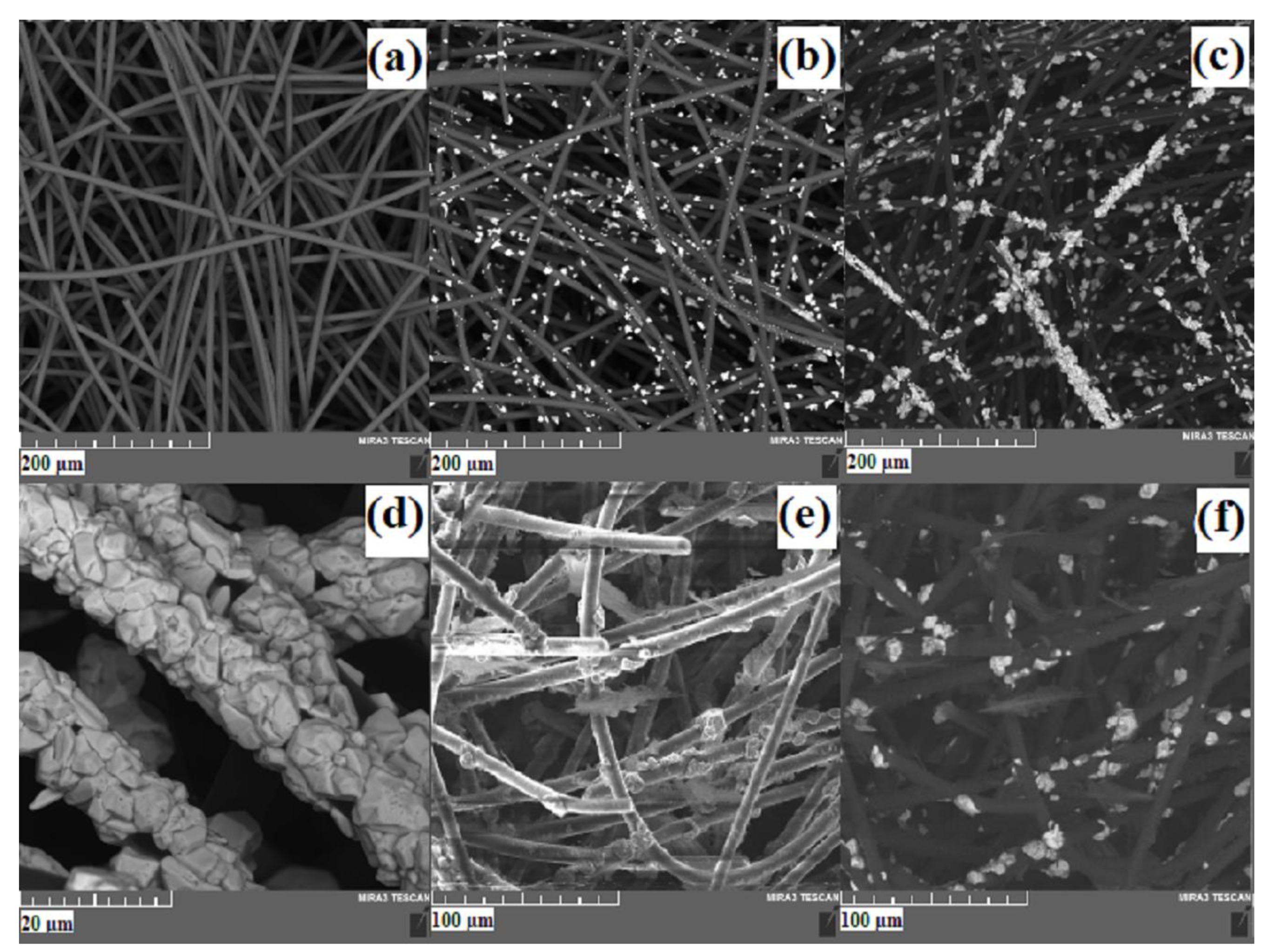
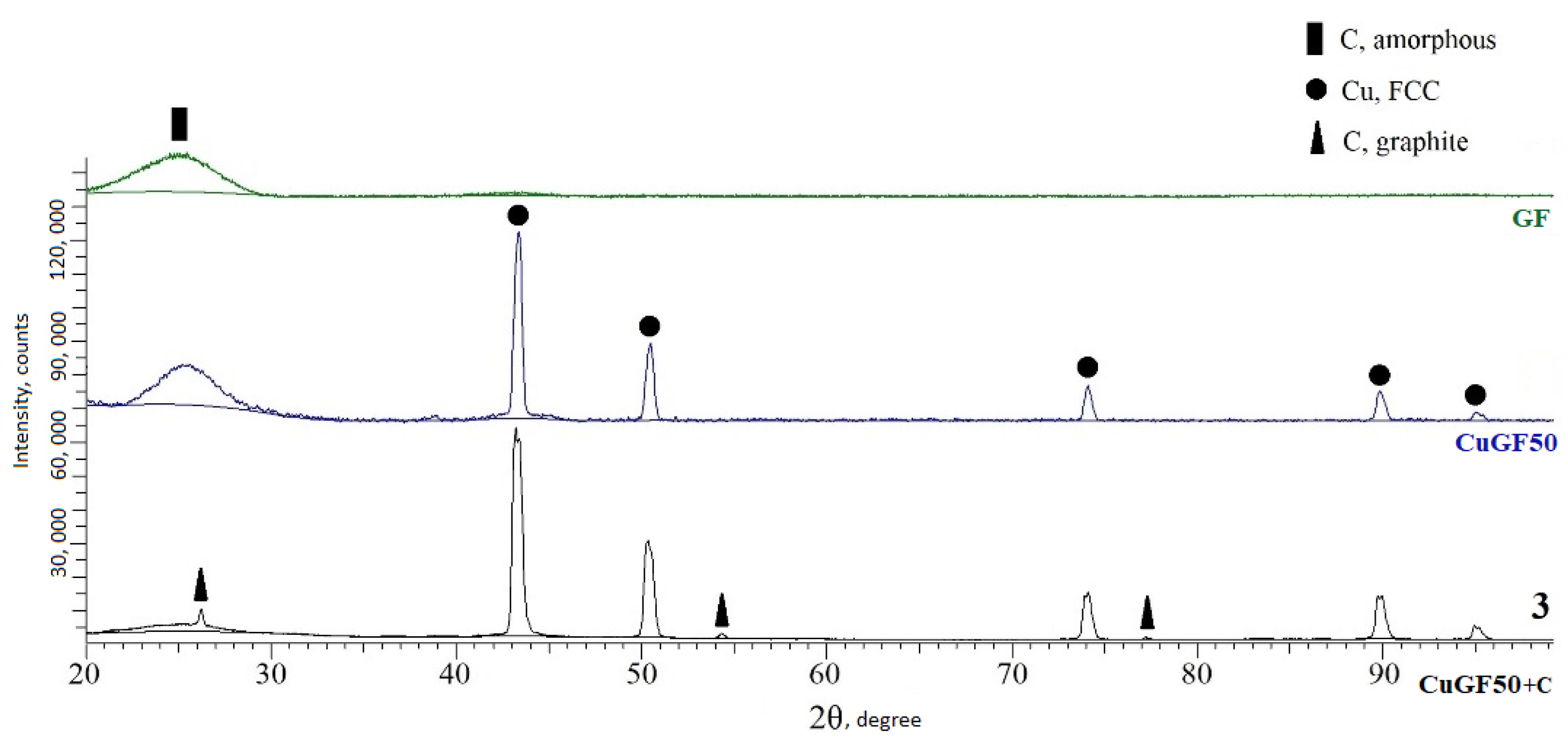
3.1. SEM, EDX and XRD Analysis of Initial Materials and Investigated Samples

Figure 2 shows SEM images of the initial materials and obtained samples.
Initial graphite felt shown in Figure 2a, it exhibits a typical filament structure with chaotically intertwined strands of carbon fiber with a diameter of about 8 microns. Figure 2b shows a sample of CuGF20. Deposited copper particles on the fiber is represented as uniformly distributed crystals of a coarse pyramidal structure. The size of the deposited crystals is less than 10 microns. For the sample CuGF50 (Figure 2c), copper deposition is less uniform. Copper-coated fibers are observed to a greater extent than others. The deposited copper crystals have a size comparable to the crystals on the sample CuGF20. On the sample CuGF100 (Figure 2d), fibers completely coated with copper are observed. The size of the deposited crystals does not exceed the size of the crystals on the two previous samples with deposited copper, however, a large number of smaller crystals are observed, which indicates the predominance of the nucleation process over the crystal growth process under this copper deposition regime. On Figure 2e,f CuGF50 +C sample is presented in the detection mode of secondary (e) and back-scattered (f) electrons. The microstructure of the felt is columnar fibers. The light powder particles observed in the BSE mode are due to the presence of deposited copper. On Figure 2e also nanoscale particles are observed similar in density to the felt material, thus these nanoparticles are presumably graphite.
Figure 3 presents the results of EDX mapping of samples CuGF20 (a), CuGF50 (b) and CuGF100 (c), from which we can understand the relationship of how exactly copper spreads over the felt surface during electrochemical deposition with an increase in the mass of deposited copper. At 20%, copper is deposited point-by-point on the felt, at 50% linearly and at 100% it completely enveloped the fibers of the felt.
Figure 4 shows the phase analysis of the samples. A halo in the region of 25 degrees indicates an amorphous structure of carbon felt. The presence of copper in CuGF50 and CuGF50 + C samples was observed. The presence of powder graphite is also observed in the sample CuGF50 + C. Thus, the difference between carbon felt with a structure of amorphous carbon, and powdered graphite with an obvious structure of graphite is clearly visible.

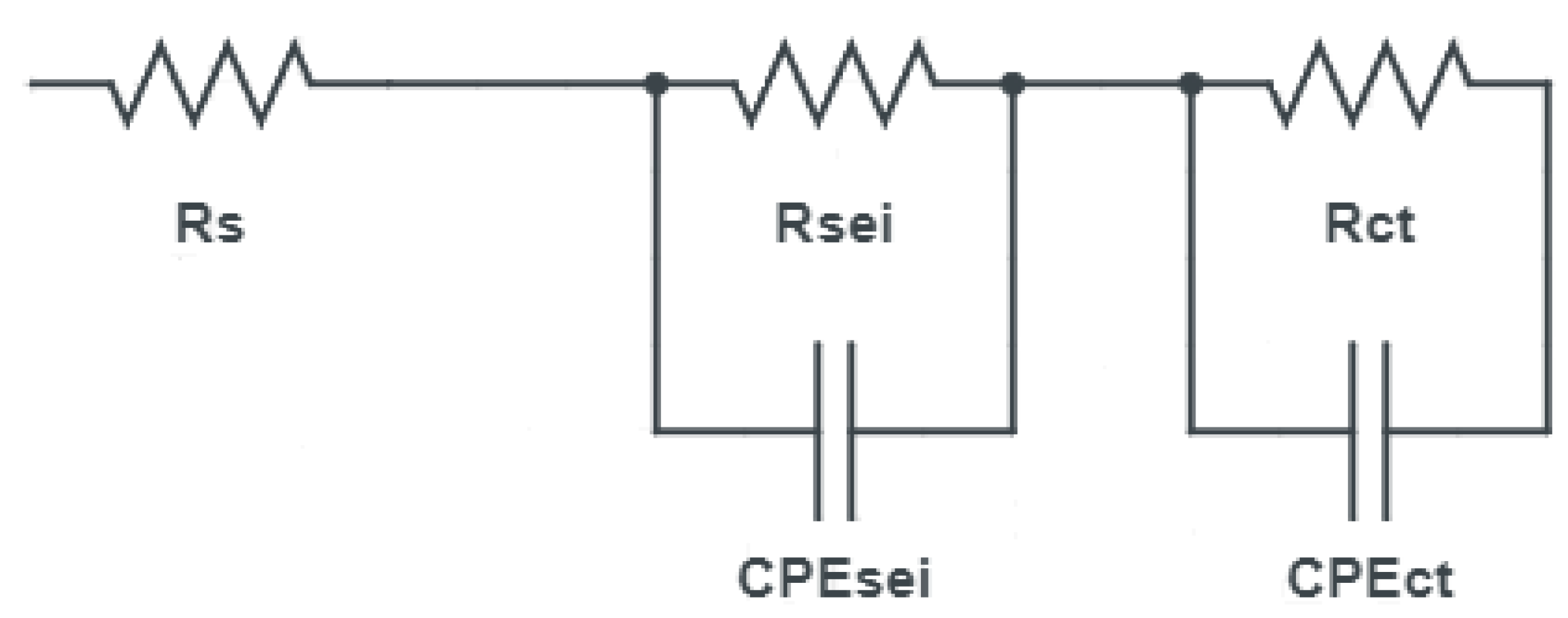
3.2. Electrochemical Analysis of Samples

The specific capacity is calculated based on the total mass of the negative electrode, unless otherwise specified. Galvanostatic charge curves of the 1st cycle of all investigated samples in the potential range of 0.01 to 1.5 V at different current densities are shown in Figure 5.
Specific capacities of all samples at 1.5 V are presented in Table 3.
If we consider the shape of the charging curves of a graphite anode and a carbon felt sample, we can observe that graphite has the main set of capacity up to 0.25 V with a slight increase in voltage, and then there is an almost vertical line of voltage growth with a slight increase in capacity. In carbon fiber, the growth goes more smoothly, and it goes to the vertical section only in the region of 1.2 V. At the same time, the specific capacity of this material is greater than that of graphite.
When carbon fiber is coated with copper, the capacity decreases. At the same time, the shape of the curve remains the same. With an increase in the mass of copper from 20% to 50%, a decrease in capacity is observed. However, for a sample with 100% of the mass of copper, the capacity is comparable to a sample of 20% of the mass.
The capacity of graphite deposited on carbon felt samples (GF + C) is slightly less than that of pure felt, but the nature of the capacity set is completely different. These samples up to 0.25 V show a plateau similar to that observed in graphite (graphite-like plateau), followed by a voltage growth area, but smoother compared to graphite.
In CuGF + C samples the shape of the charge curve differs depending on the mass of the copper coating. The sample CuGF100 + C has a plateau almost identical to that of graphite, but the voltage growth area is somewhat smoother, due to which the final capacity is higher than that of graphite. With a mass of 50% copper, the curve corresponds in shape to the GF + C sample but has a slightly smaller capacity.
With a further decrease down to the the mass of copper up to 20%, the smoothing of graphite-like plateau can be observed. After 0.25 V, the curve is identical in shape to the carbon felt. The specific capacity of this sample is the largest among all the studied electrodes.
Figure 6a shows the cyclic voltamperogramms of the anode made of graphite and carbon felt. It can be noted that the smoother nature of the capacity set, which was noted above, can be noticed here. This may be due to the presence of micro-crystallite composed of several ordered graphene layers [46]. The peak around 0.82 V corresponds to the insertion or extraction of Li in the disordered accommodation vacancy [47,48].
On Figure 6b it can be noted that the position of the peaks for a sample with 50% of the copper mass differs from 20% and 100%: 0.235 V (vs. 0.27 and 0.29 V, respectively) and 0.78 V (vs. 0.8 V). This correlates with what we have observed in the behavior of charging curves.
For CuGF + C (Figure 6c) samples, the position of the most intense peaks is approximately the same for all copper masses, but the shape width decreases with increasing of copper mass. The decrease in width can be interpreted to approximate the behavior to graphite. Note that in these samples, the intensity and position of the second peak on the lower part of the half-curve also change. With an increase in the mass of copper, the intensity of these peaks decreases, and they shift to the left. This can be attributed to the approximation of the charging curve in shape to graphite.
The obtained electrochemical impedance spectra is presented on Figure 7.
It was modeled using an equivalent circuit shown in Figure 8. The RS resistor is responsible for the internal resistance of the measuring cell. The first block consisting of a constant phase element and a resistor connected to it can be associated with SEI parameters. The second block corresponds to the charge transfer processes during intercalation of lithium ions. Table 4 shows the resistances of equivalent circuits for different samples.
It can be mentioned that samples without graphite have less SEI resistance than samples with graphite. This is probably due to a different morphology of the surface. The addition of a copper coating reduces the charge transfer resistance. This can be explained by the higher electronic conductivity of copper compared to carbon. However, it can be noticed that the CuGF50 + C sample is out of the general trends. The RSEI and RCT resistances for this sample are several times greater than for others.
It can be concluded that the copper coating increases the capacity of the samples. Presumably, this effect can be explained by the better electrical conductivity of copper. However, with an increase in the mass of the coating, its continuity also increases, which leads to the isolation of the deposited graphite particles from the surface of the carbon block and changes the nature of the capacity set. So at 50% there is a transition period when the coating already occupies a fairly large area, but not yet solid. At this stage, we see a serious deterioration in performance. However, with a sufficiently solid coating, this electrode behaves like graphite on a copper foil. However, due to the more developed surface, the capacitive characteristics of such electrodes are higher.

4. Conclusions

GF-based anode materials, such as the pristine GF, graphite coated GF, copper-coated GF, and GF coated with copper and graphite simultaneously were successfully obtained and compared. The composition of the electrodes and their morphology have been characterized using X-ray diffraction, scanning electron microscopy and energy-dispersive X-ray spectroscopy methods of analysis. To characterize electrochemical performance such techniques as EIS, CVA and charge/discharge was used.
Samples with a specific capacity of up to 473 mAh∙g−1were obtained, which exceeds the specific capacity of a conventional graphite anode. It was also found that graphite felt has a different type of capacity set compared to graphite, which is presumably due to differences in microstructure. When graphite and graphite felt are used together, they work synergistically, increasing the capacity. It was also noted that the addition of a copper coating increases the specific capacitance and reduces the resistance to charge transfer, which may be due to the better electronic conductivity of copper. However, with an increase in the mass of the coating, the morphology of the surface and the mechanisms of capacity recruitment change. It was determined that a coating with a mass of about 20% of the mass of the anode is optimal. The obtained materials can be used in LIBS as anodes with a high specific capacity.

Author Contributions

Conceptualization P.N. and K.P.; methodology, A.A.P. (Alexander A. Pavlovskii), K.P. and A.K.; software, K.P. and A.K.; validation, K.P. and A.K.; formal analysis, K.P., A.K. and V.C.; investigation, A.A.P. (Alexander A. Pavlovskii), K.P. and A.K.; resources A.A.P. (Anatoliy A. Popovich) and P.N.; data curation, K.P. and A.K.; writing—original draft preparation, A.A.P. (Alexander A. Pavlovskii); writing—review and editing, K.P., A.K. and V.C.; visualization, A.A.P. (Alexander A. Pavlovskii); supervision, K.P., P.N. and A.A.P. (Anatoliy A. Popovich); project administration, P.N.; funding acquisition, P.N. All authors have read and agreed to the published version of the manuscript.

Funding

The research is funded by the Ministry of Science and Higher Education of the Russian Federation under the strategic academic leadership program “Priority 2030” (Agreement 075-15-2021-1333 dated 30 September 2021).

Institutional Review Board Statement

Not applicable.

Informed Consent Statement

Not applicable.

Data Availability Statement

Not applicable.

Conflicts of Interest

The authors declare no conflict of interest.

References

  1. Ozawa, K. Lithium-Ion Rechargeable Batteries with LiCoO2 and Carbon Electrodes: The LiCoO2/C System. Solid State Ion. 1994, 69, 212–221. [Google Scholar] [CrossRef]
  2. Armand, M.; Tarascon, J.M. Building Better Batteries. Nature 2008, 451, 652–657. [Google Scholar] [CrossRef] [PubMed]
  3. Cho, J.; Bruce, P.G.; Choi, N.-S.; Chen, Z.; Freunberger, S.A.; Ji, X.; Sun, Y.-K.; Amine, K.; Yushin, G.; Nazar, L.F. Challenges Facing Lithium Batteries and Electrical Double-Layer Capacitors. Angew. Chem. Int. Ed. 2012, 51, 9994–10024. [Google Scholar] [CrossRef] [PubMed]
  4. Sanders, M. Lithium-Ion Battery Raw Material Supply and Demand 2016–2025. In Proceedings of the the Advanced Automotive Battery Conference, San Francisco, CA, USA, 19–22 June 2017; pp. 162–181. [Google Scholar]
  5. Curry, C. Bloomberg New Energy Finance 2017. pp. 4–6. Available online: https://data.bloomberglp.com/bnef/sites/14/2017/07/BNEF-Lithium-ion-battery-costs-and-market.pdf (accessed on 20 July 2022).
  6. Chen, S.; Qiu, L.; Cheng, H.-M. Carbon-Based Fibers for Advanced Electrochemical Energy Storage Devices. Chem. Rev. 2020, 120, 2811–2878. [Google Scholar] [CrossRef]
  7. Julien, C.; Mauger, A.; Vijh, A.; Zaghib, K. Lithium Batteries: Science and Technology; Springer International Publishing: Cham, Switzerland, 2015. [Google Scholar]
  8. Deng, D. Li-Ion Batteries: Basics, Progress, and Challenges. Energy Sci. Eng. 2015, 3, 385–418. [Google Scholar] [CrossRef]
  9. Yang, Z.; Zhang, J.; Kintner-Meyer, M.C.W.; Lu, X.; Choi, D.; Lemmon, J.P.; Liu, J. Electrochemical Energy Storage for Green Grid. Chem. Rev. 2011, 111, 3577–3613. [Google Scholar] [CrossRef]
  10. Candelaria, S.L.; Shao, Y.; Zhou, W.; Li, X.; Xiao, J.; Zhang, J.G.; Wang, Y.; Liu, J.; Li, J.; Cao, G. Nanostructured Carbon for Energy Storage and Conversion. Nano Energy 2012, 1, 195–220. [Google Scholar] [CrossRef]
  11. Liang, M.; Zhi, L. Graphene-Based Electrode Materials for Rechargeable Lithium Batteries. J. Mater. Chem. 2009, 19, 5871–5878. [Google Scholar] [CrossRef]
  12. Snyder, J.F.; Wong, E.L.; Hubbard, C.W. Evaluation of Commercially Available Carbon Fibers, Fabrics, and Papers for Potential Use in Multifunctional Energy Storage Applications. J. Electrochem. Soc. 2009, 156, A215. [Google Scholar] [CrossRef]
  13. Jacques, E.; Kjell, M.H.; Zenkert, D.; Lindbergh, G. The Effect of Lithium-Intercalation on the Mechanical Properties of Carbon Fibres. Carbon 2014, 68, 725–733. [Google Scholar] [CrossRef]
  14. Asp, L.E. Multifunctional Composite Materials for Energy Storage in Structural Load Paths. Plast. Rubber Compos. 2013, 42, 144–149. [Google Scholar] [CrossRef]
  15. Hagberg, J.; Leijonmarck, S.; Lindbergh, G. High Precision Coulometry of Commercial PAN-Based Carbon Fibers as Electrodes in Structural Batteries. J. Electrochem. Soc. 2016, 163, A1790–A1797. [Google Scholar] [CrossRef]
  16. Javed, M.S.; Shaheen, N.; Hussain, S.; Li, J.; Shah, S.S.A.; Abbas, Y.; Ahmad, M.A.; Raza, R.; Mai, W. An Ultra-High Energy Density Flexible Asymmetric Supercapacitor Based on Hierarchical Fabric Decorated with 2D Bimetallic Oxide Nanosheets and MOF-Derived Porous Carbon Polyhedra. J. Mater. Chem.A 2019, 7, 946–957. [Google Scholar] [CrossRef]
  17. Javed, M.S.; Shah, S.S.A.; Najam, T.; Siyal, S.H.; Hussain, S.; Saleem, M.; Zhao, Z.; Mai, W. Achieving High-Energy Density and Superior Cyclic Stability in Flexible and Lightweight Pseudocapacitor through Synergic Effects of Binder-Free CoGa2O4 2D-Hexagonal Nanoplates. Nano Energy 2020, 77, 105276. [Google Scholar] [CrossRef]
  18. Donnet, J.B.; Bansal, R.C. Carbon Fibers, 2nd ed.; Marcel Dekker, Inc.: New York, NY, USA, 1990. [Google Scholar]
  19. Shao, Y.; Cheng, Y.; Duan, W.; Wang, W.; Lin, Y.; Wang, Y.; Liu, J. Nanostructured Electrocatalysts for PEM Fuel Cells and Redox Flow Batteries: A Selected Review. ACS Catal. 2015, 5, 7288–7298. [Google Scholar] [CrossRef]
  20. Zhang, Z.; Xi, J.; Zhou, H.; Qiu, X. KOH Etched Graphite Felt with Improved Wettability and Activity for Vanadium Flow Batteries. Electrochim. Acta 2016, 218, 15–23. [Google Scholar] [CrossRef]
  21. Wu, L.; Wang, J.; Shen, Y.; Liu, L.; Xi, J. Electrochemical Evaluation Methods of Vanadium Flow Battery Electrodes. Phys. Chem. Chem. Phys. 2017, 19, 14708–14717. [Google Scholar] [CrossRef]
  22. Castañeda, L.F.; Walsh, F.C.; Nava, J.L.; Ponce de León, C. Graphite Felt as a Versatile Electrode Material: Properties, Reaction Environment, Performance and Applications. Electrochim. Acta 2017, 258, 1115–1139. [Google Scholar] [CrossRef]
  23. Fauteux, D.; Koksbang, R. Rechargeable Lithium Battery Anodes: Alternatives to Metallic Lithium. J. Appl. Electrochem. 1993, 23, 1–10. [Google Scholar] [CrossRef]
  24. Kabtamu, D.M.; Chen, J.Y.; Chang, Y.C.; Wang, C.H. Water-Activated Graphite Felt as a High-Performance Electrode for Vanadium Redox Flow Batteries. J. Power Sources 2017, 341, 270–279. [Google Scholar] [CrossRef]
  25. Jianga, F.; Heb, Z.; Guoa, D.; Zhoua, X. Carbon Aerogel Modified Graphite Felt as Advanced Electrodes for Vanadium Redox Flow Batteries. J. Power Sources 2019, 440, 227114. [Google Scholar] [CrossRef]
  26. Pu, K.B.; Lu, C.X.; Zhang, K.; Zhang, H.; Chen, Q.Y.; Wang, Y.H. In Situ Synthesis of Polypyrrole on Graphite Felt as Bio-Anode to Enhance the Start-up Performance of Microbial Fuel Cells. Bioprocess Biosyst. Eng. 2020, 43, 429–437. [Google Scholar] [CrossRef] [PubMed]
  27. Liang, Y.; Zhai, H.; Liu, B.; Ji, M.; Li, J. Carbon Nanomaterial-Modified Graphite Felt as an Anode Enhanced the Power Production and Polycyclic Aromatic Hydrocarbon Removal in Sediment Microbial Fuel Cells. Sci. Total Environ. 2020, 713, 136483. [Google Scholar] [CrossRef] [PubMed]
  28. Shen, P.; Wang, Z.; Yang, C.; Zhao, L.; Liu, T.; Shen, M.; Li, J.; Qian, D. Enhanced Electrochemical Property of Graphite Felt@Co2(OH)2CO3 via Ni−P Electrodeposition for Flexible Supercapacitors. Electrochim. Acta 2018, 283, 1568–1577. [Google Scholar] [CrossRef]
  29. Park, C.; Hwang, J.; Hwang, Y.T.; Song, C.; Ahn, S.; Kim, H.S.; Ahn, H. Intense Pulsed White Light Assisted Fabrication of Co-CoOx Core-Shell Nanoflakes on Graphite Felt for Flexible Hybrid Supercapacitors. Electrochim. Acta 2017, 246, 757–765. [Google Scholar] [CrossRef]
  30. Davis, F.; Higson, S.P.J. Biofuel Cells-Recent Advances and Applications. Biosens. Bioelectron. 2007, 22, 1224–1235. [Google Scholar] [CrossRef]
  31. Tayhas, G.; Palmore, R.; Bertschy, H.; Bergens, S.H.; Whitesides, G.M. A Methanol/Dioxygen Biofuel Cell That Uses NAD+ -dependent Dehydrogenases as Catalysts: Application of an Electro-Enzymatic Method to Regenerate Nicotinamide Adenine Dinucleotide at Low Overpotentials. J. Electroanal. Chem. 1998, 443, 155–161. [Google Scholar]
  32. Zhang, Y.; Zuo, S.; Zhou, M.; Liang, L.; Ren, G. Removal of Tetracycline by Coupling of Flow-through Electro-Fenton and in-Situ Regenerative Active Carbon Felt Adsorption. Chem. Eng. J. 2018, 335, 685–692. [Google Scholar] [CrossRef]
  33. Liang, L.; Yu, F.; An, Y.; Liu, M.; Zhou, M. Preparation of Transition Metal Composite Graphite Felt Cathode for Efficient Heterogeneous Electro-Fenton Process. Environ. Sci. Pollut. Res. 2017, 24, 1122–1132. [Google Scholar] [CrossRef]
  34. Liu, X.; Yang, D.; Zhou, Y.; Zhang, J.; Luo, L.; Meng, S.; Chen, S.; Tan, M.; Li, Z.; Tang, L. Electrocatalytic Properties of N-Doped Graphite Felt in Electro-Fenton Process and Degradation Mechanism of Levofloxacin. Chemosphere 2017, 182, 306–315. [Google Scholar] [CrossRef]
  35. Le, T.X.H.; Bechelany, M.; Cretin, M. Carbon Felt Based-Electrodes for Energy and Environmental Applications: A Review. Carbon 2017, 122, 564–591. [Google Scholar] [CrossRef]
  36. Chen, S.; Hu, W.; Hong, J.; Sandoe, S. Electrochemical Disinfection of Simulated Ballast Water on PbO2/Graphite Felt Electrode. Mar. Pollut Bull. 2016, 105, 319–323. [Google Scholar] [CrossRef] [PubMed]
  37. Dixon, D.; Babu, D.J.; Langner, J.; Bruns, M.; Pfaffmann, L.; Bhaskar, A.; Schneider, J.J.; Scheiba, F.; Ehrenberg, H. Effect of Oxygen Plasma Treatment on the Electrochemical Performance of the Rayon and Polyacrylonitrile Based Carbon Felt for the Vanadium Redox Flow Battery Application. J. Power Sources 2016, 332, 240–248. [Google Scholar] [CrossRef]
  38. Sun, B.; Skyllas-Kazacos, M. Modification of Graphite Electrode Materials for Vanadium Redox Flow Battery Application-I. Thermal Treatment. Electrochim. Acta 1992, 37, 1253–1260. [Google Scholar] [CrossRef]
  39. Pezeshki, A.M.; Clement, J.T.; Veith, G.M.; Zawodzinski, T.A.; Mench, M.M. High Performance Electrodes in Vanadium Redox Flow Batteries through Oxygen-Enriched Thermal Activation. J. Power Sources 2015, 294, 333–338. [Google Scholar] [CrossRef]
  40. Chang, Y.; Deng, L.; Meng, X.; Zhang, W.; Wang, C.; Wang, Y.; Zhao, S.; Lin, L.; Crittenden, J.C. Closed-Loop Electrochemical Recycling of Spent Copper (II) from Etchant Wastewater Using a Carbon Nanotube Modified Graphite Felt Anode. Environ. Sci. Technol. 2018, 52, 5940–5948. [Google Scholar] [CrossRef]
  41. Flox, C.; Rubio-García, J.; Skoumal, M.; Andreu, T.; Morante, J.R. Thermo-Chemical Treatments Based on NH3/O2 for Improved Graphite-Based Fiber Electrodes in Vanadium Redox Flow Batteries. Carbon 2013, 60, 280–288. [Google Scholar] [CrossRef]
  42. Sun, B.; Skyllas-Kazacos, M. Chemical Modification of Graphite Electrode Materials for Vanadium Redox Flow Battery Application—Part II. Acid Treatments. Electrochim. Acta 1992, 37, 2459–2465. [Google Scholar] [CrossRef]
  43. Wei, L.; Zhao, T.S.; Zeng, L.; Zhou, X.L.; Zeng, Y.K. Copper Nanoparticle-Deposited Graphite Felt Electrodes for All Vanadium Redox Flow Batteries. Appl. Energy 2016, 180, 386–391. [Google Scholar] [CrossRef]
  44. Shen, Y.; Xu, H.; Xu, P.; Wu, X.; Dong, Y.; Lu, L. Electrochemical Catalytic Activity of Tungsten Trioxide- modified Graphite Felt toward VO2+/VO2+ Redox Reaction. Electrochim. Acta 2014, 132, 37–41. [Google Scholar] [CrossRef]
  45. Xiang, Y.; Daoud, W.A. Investigation of an Advanced Catalytic Effect of Cobalt Oxide Modification on Graphite Felt as the Positive Electrode of the Vanadium Redox Flow Battery. J. Power Sources 2019, 416, 175–183. [Google Scholar] [CrossRef]
  46. Carotenuto, G.; Gallo, A.; Nicolais, L. Wettability of Copper Coated Carbon Fibers. Adv. Compos. Lett. 1994, 3, 139–143. [Google Scholar] [CrossRef]
  47. Saito, M.; Yamaguchi, K.; Sekine, K.; Takamura, T. On the Improvement of Li Charge/Discharge Cyclability of Carbon Fibers by Making a C/C Composite with Thermosetting Resins. Solid State Ion. 2000, 135, 199–207. [Google Scholar] [CrossRef]
  48. Mabuchi, A.; Tokumitsu, K.; Fujimoto, H.; Kasuh, T. Charge-Discharge Characteristics of the Mesocarbon Miocrobeads Heat-Treated at Different Temperatures. J. Electrochem. Soc. 1995, 142, 1041–1046. [Google Scholar] [CrossRef]
Figure 1. The schematic diagram of all investigated samples.
Coatings 12 01321 g001
Figure 2. SEM images of the initial materials and obtained samples: (a)–graphite felt, (b) CuGF20, (c) CuGF50, (d) CuGF100, (e) CuGF50 + C in SE mode, (f) CuGF50 + C in BSE mode.
Coatings 12 01321 g002
Figure 3. EDX -mapping images of copper-deposited graphite felt samples: (a) CuGF20, (b) CuGF50, and (c) CuGF100.
Coatings 12 01321 g003
Figure 4. Diffractograms of GF, CuGF50 and CuGF50 + C samples.
Coatings 12 01321 g004
Figure 5. Charge curves of investigated samples.
Coatings 12 01321 g005
Figure 6. CVA of the studied electrodes (a)-graphite and carbon felt; (b)-carbon felt with copper; (c)-carbon felt with copper and graphite.
Coatings 12 01321 g006
Figure 7. EIS of investigated electrodes.
Coatings 12 01321 g007
Figure 8. The equivalent circuit for EIS fitting.
Coatings 12 01321 g008
Table 1. Masses of samples and the mass distribution of materials. All masses are in milligrams.
SampleC1C2GF1GF2GF + C1GF + C2CuGF
20 + C
CuGF
50 + C
CuGF
100 + C
CuGF
20
CuGF
50
CuGF
100
Electrode, mass 41.1641.3923.9222.5936.4238.9947.5958.7065.8526.5936.1545.17
Graphite felt, mass--23.9222.5923.6823.6824.4625.7621.3823.0023.4522.71
Deposited copper, mass------4.7814.4223.423.5912.722.46
Foil, mass22.8022.80----------
Active material, mass16.8617.10--11.6814.0816.8817.0419.37---
Binder, mass0.900.93--0.680.770.920.931.05---
Conductive additive, mass0.600.56--0.380.460.550.550.63---
Table 2. Charge-discharge cycling program.
No.StepTime, minVoltage, VCurrent Density, mA/g *Process
1Rest5---
2Discharge6000.011Lithiation, SEI formation
3Rest5---
4Discharge 0.0110Lithiation
5Discharge 0.015
6Discharge 0.011
7Rest5---
8Charge 1.510Delithiation
* Current densities were calculated relative to the mass of the electrodes.
Table 3. Specific capacities of all samples at 1.5 V.
SampleCGFGF + CCuGF20 + CCuGF50 + CCuGF100 + CCuGF20CuGF50CuGF100
Specific
capacity, mAh∙g−1
143.5333300.8473292.6184.8254.4200.4265.1
Table 4. The resistance of equivalent circuits for different samples.
SampleCGFGF + CCuGF20 + CCuGF50 + CCuGF100 + CCuGF20CuGF50CuGF100
RS, Ω4.22.81.112.75.74.33.94.2
RSEI, Ω61.221.757.62.8214.421.87.22.85
RCT, Ω44.63013.916.9119.59.79.46.37
Publisher’s Note: MDPI stays neutral with regard to jurisdictional claims in published maps and institutional affiliations.

