Article

The Influence of Ni Content on the Microstructure and Impact Wear Resistance Performance of High-Chromium Casting Infiltration Coating

1
National Joint Engineering Research Center for Abrasion Control and Molding of Metal Materials, Henan University of Science and Technology, Luoyang 471000, China
2
Longmen Laboratory, Luoyang 471000, China
*
Authors to whom correspondence should be addressed.
These authors contributed equally to this work.
Coatings 2022, 12(9), 1313; https://doi.org/10.3390/coatings12091313
Submission received: 11 August 2022 / Revised: 1 September 2022 / Accepted: 6 September 2022 / Published: 8 September 2022

Abstract

:
Casting infiltration technology was used to fabricate a high-chromium coating on the surface of parent ZG45 steel with different Ni content. SEM, EDS analysis, CALPHAD-type calculations, Rockwell hardness test and impact wear test were utilized to investigate the influence of Ni on the microstructure, hardness and impact wear resistance performance. The as-cast microstructure of the casting infiltration coatings with Ni content less than 2.82 wt.% was a pearlite matrix with reticular eutectic M7C3 carbide, while the matrix of the coatings with 5.53 wt.% Ni showed austenite. The content of Ni had little effect on both the solidification behavior and the amount of eutectic M7C3. After heat treatment, the transformation of the matrix to martensite occurred, and the Rockwell hardness significantly increased. The proportion of the retained austenite in the casting infiltration coatings increased from 6.4 vol.% to 27.5 vol.% with increasing Ni content, resulting in a decrease in the hardness. Due to a better balance of the hardness and toughness, the casting infiltration coating with 1.53 wt.% Ni showed the best impact wear resistance performance.

1. Introduction

Abrasion wear is one of the determinants controlling the service life of many key engineering parts [1,2,3]. The abrasion wear mainly occurs on the working surfaces of the parts, leading to progressive material loss and final failure. Due to the extremely high maintenance and frequent replacement costs, failures should be kept to a minimum [4,5].
The improvement of wear resistance is an ongoing process that can be realized by surface-strengthening technology. Different methods were utilized to fabricate wear resistance coatings. These include laser cladding [6], thermal spraying [7], ion implantation [8], plasma arc welding [9], etc. However, the thickness of the obtained coating is usually less than 2 mm, which is inadequate for severe wear. As a one-step manufacturing technology, the casting infiltration method is widely used to prepare surface composite material [10,11]. A wear-resistant casting infiltration coating (CIC) with a thickness greater than 5 mm is simultaneously formed at the casting surface. Compared with 3D printing techniques [12,13,14,15], this method is usually utilized for parts with simpler construction, and the cost is much lower.
The casting infiltration technology and the obtained CICs have been extensively investigated [16,17,18,19]. High-chromium CICs with the formation of high-hardness Cr7C3 carbides are most favored. Different heat treatments are usually performed to further improve the wear resistance performance as the result of the transformation of the matrix to martensite and the precipitation of secondary carbides [20,21]. Great efforts at casting infiltration were conducted to improve wear resistance by introducing additional hard phases, such as carbides (VC, Nb, WC, TiC, etc) [11,22], oxides (Al2O3, ZrO2, etc.) [23] and borides (Feb, Fe2B, etc.) [16,24]. Wang et al. [25] fabricated a high-vanadium alloy coating on carbon steel. Due to the existence of primary VC and fine VC, the impact and abrasive wear resistance, compared with those of Cr20, increased by 26% and 60%, respectively. A white cast iron surface coating enriched with FeB was prepared on gray cast iron by Fischer et al. [16] through the casting infiltration method. The microhardness reached 505 HV. Zirconia-toughened alumina particles reinforced CIC prepared on high chromium cast iron was investigated by Qiu et al. [26], and the relative impact wear resistance under impact energy of 1.5 J was 2.35 times that of the matrix.
Due to the complexity of the tribological systems commonly encountered in services, a combination of resistance to abrasion wear and impact is usually required [27]. Most of the related investigations of the CICs focused on the introduction of high-hardness phases. The brittle characteristics of the CIC and the bonding between the CIC and the matrix limited the application in working conditions under certain impact energies. The impact wear resistance of a material is greatly influenced by the metallic matrix structure [28]. The presence of retained austenite greatly affects the impact wear resistance. Only a slight weight loss can be achieved with greater improvement in toughness [29].
Nickel is commonly added in high-chromium cast alloys to improve hardenability. As an austenite stable element, Ni also lowers the Ms temperature of the austenite, and more retained austenite can be obtained after heat treatment [30]. Detailed investigations related to the influence of Ni on the impact wear resistance of the CICs are limited. In the present work, high-Cr wear-resistant CICs with different Ni contents were designed and fabricated on ZG45, aimed at obtaining an optimal Ni content for improving the impact wear resistance. The purposes of this work were: (i) to research the microstructure of as-cast and heat-treated CICs; (ii) to analyze the formation of the interface between the parent metal and the CICs; and (iii) to reveal the effect of Ni on the impact wear resistance performance of the CICs.

2. Materials and Methods
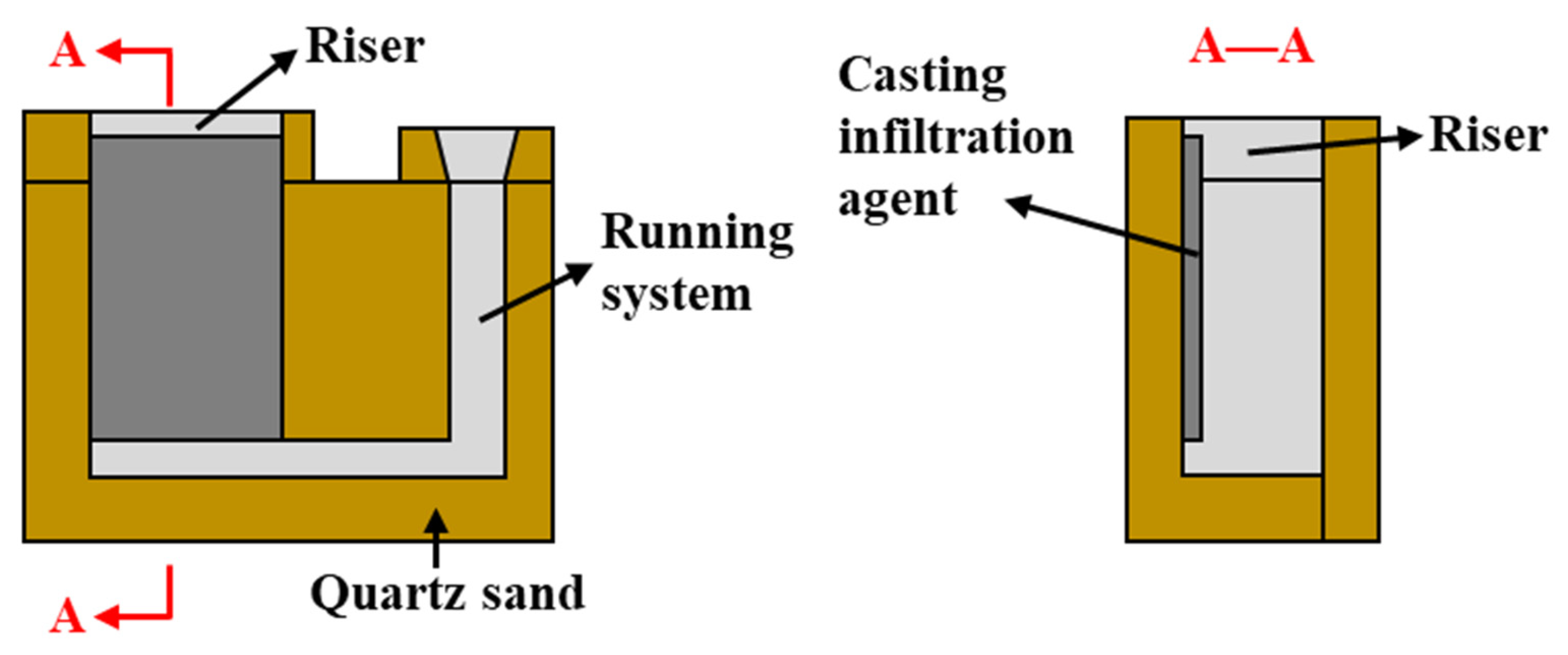
2.1. Materials

A sand mold casting process was used to prepare high-chromium CICs with various Ni contents on medium carbon steel ZG45. The raw materials utilized were high-carbon ferrochrome powders (75 wt.% Cr, 10 wt.% C), pure nickel powders (99.95 wt.% purity) and pure chromium powders (99.95 wt.% purity) with a powder size of 60 mesh. The normal alloy compositions of the casting infiltration agents with different Ni contents are listed in Table 1. Alcohol and adhesive polyvinyl butyral resin with a mass proportion of 20:1 was mixed with the alloy powders in a ball mill for 4 h. Figure 1 gives the schematic diagram of the sand mold used for the casting infiltration. The powder slurry was coated onto the mold with 5 mm thickness and then ignited to form a preform. ZG45 was melted in a medium-frequency furnace and then poured at 1680 °C. The molten steel melted the powder preform, resulting in the formation of the CIC at the surface of ZG45 casting. The casting samples with different Ni contents in the CICs were subjected to a destabilization-subcritical heat treatment in a resistance furnace. They were austenitized at 1000 °C for 2 h, air cooled, tempered at 250 °C for 2 h and then air cooled again.

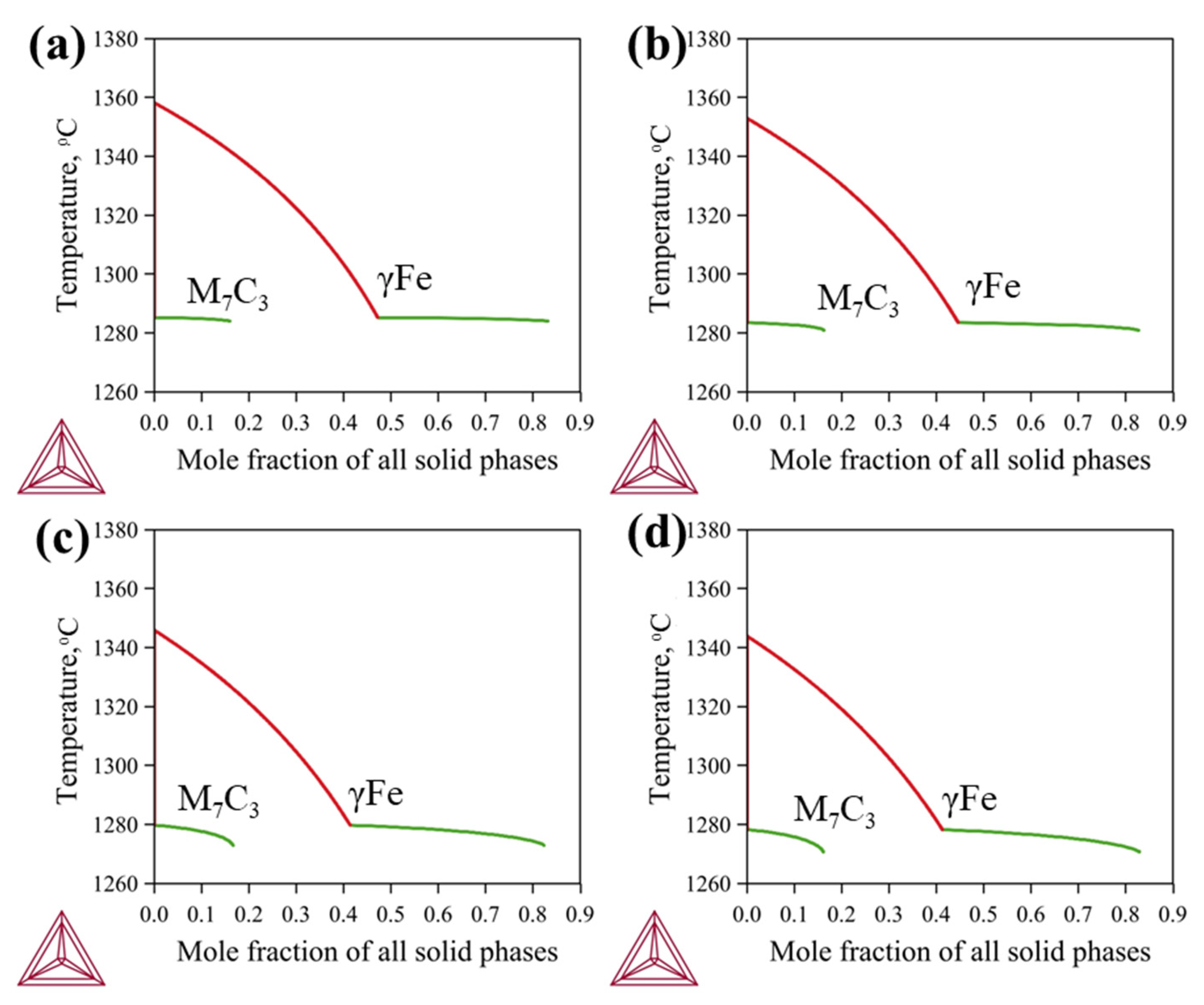
2.2. Thermodynamic Calculations

The CALPHAD (CALculation of PHase Diagram) method has been extensively applied for understanding the microstructure evolution of various materials [31]. Thermodynamic calculations based on this method were conducted using Thermo-Calc software (2022b) and a thermodynamic database established in our previous work [32]. The modified Scheil–Gulliver simulations were performed to understand the solidification behaviors of the CICs [33]. A vertical section along the compositions from Fe-0.45C (wt.%) to Fe-20Cr-2C (wt.%) was calculated to realize the interfacial microstructure.

2.3. Microstructure Observation

An X-ray fluorescence spectrometer (EDX-1050, Shanshiyiqi, Shenzhen, China) was used to determine the actual chemical compositions of the CICs. The cross sections of the as-cast and heat-treated samples were ground and polished, followed by natal etching. The microstructures were observed using an optical microscope and scanning electron microscope (SEM, JSM-IT 800SHL, Jeol, Akishima-shi, Tokyo, Japan). The amounts of the M7C3 phase in the as-cast CICs and residual austenite in the heat-treated CICs were determined using ImageJ software and the values averaged from five different images. Energy-dispersive X-ray spectroscopy (EDX, Ultim Max 40, Oxford instruments, Oxford, England) was used to analyze the elemental concentrations.

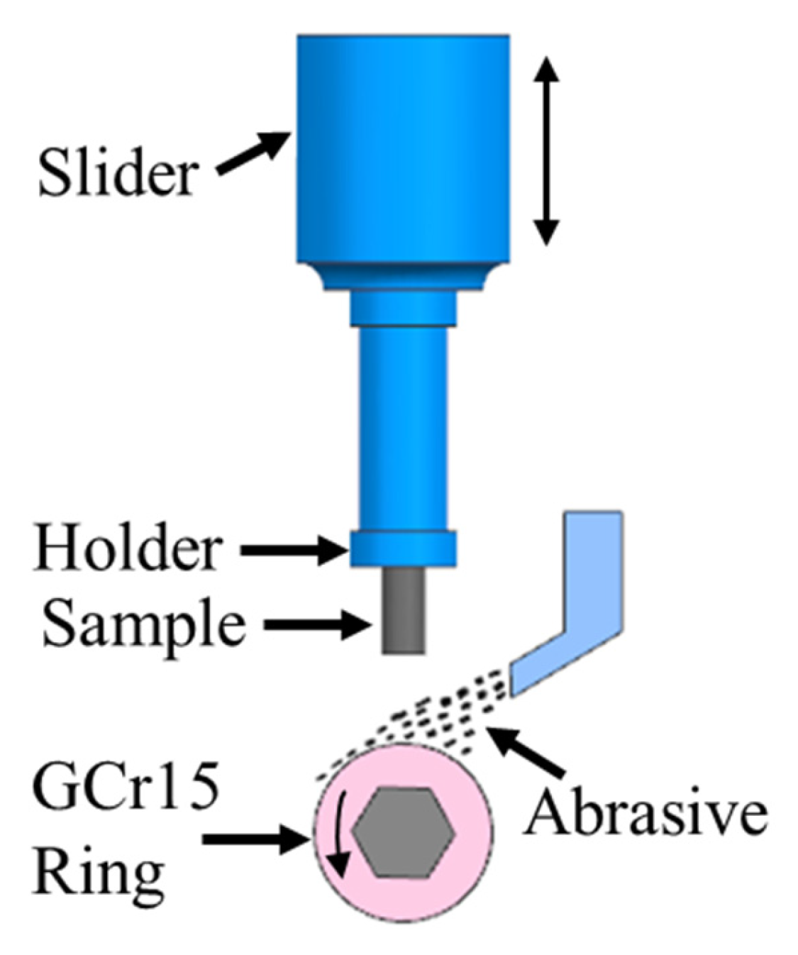
2.4. Hardness Measurement and Impact Wear Test

The Rockwell hardness tests on the CICs before and after heat treatment were performed on a HRD-150 Rockwell hardness tester (Huayin, Laizhou, China). Five values were averaged for the determination for each sample.
The impact wear tester MLD-10 (Chengxin, Zhangjiakou, China). shown in Figure 2 was utilized to investigate the impact wear performance of the surface composite materials with quartz sand as the abrasive. Impact energy of 2 J was applied. The impact frequency of the samples with the dimensions of 10 mm × 10 mm × 25 mm was 200 times per minute. The flow rate was set to 800 g/min for the quartz sand with a hardness of approximately 1100 HV. Each sample was tested for 50 min. An analytical balance (TG328B, Haida, Xiamen, China) was used to measure the mass loss. Three sets of parallel experiments were performed, and the mass loss was averaged from the test values. The worn cross sections and the worn surface morphologies were observed with SEM.

3. Results and Discussion

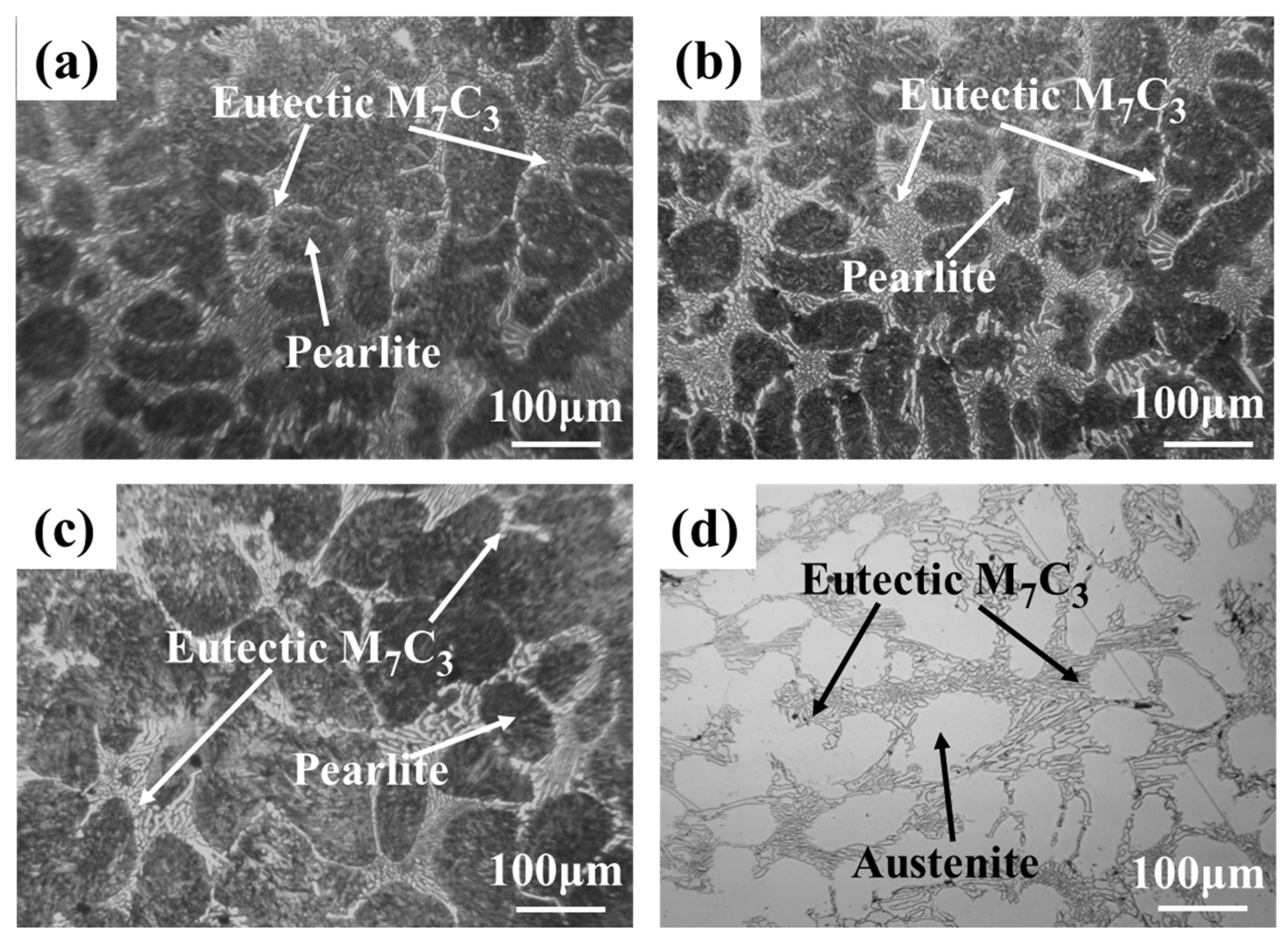
3.1. Microstructure of the As-Cast Samples

The powders in the casting agent were melted due to the infiltration of molten steel into the powder preforms, and the chemical compositions of the CICs were thus changed compared with those of the casting infiltration agents [34]. Table 1 lists the actual chemical compositions of the CICs. CICs with various Ni contents were formed, and the contents of Cr and C in CICs were about 20 wt.% and 2 wt.%, respectively.
The solidification behaviors of the CICs were simulated using Thermo-Calc software with the modified Scheil–Gulliver model. Calculated solidification paths are shown in Figure 3, which gives the mole fractions of all solid phases with decreases in temperature. During simulation, carbon was assumed to be redistributed rapidly, and its back diffusion was taken into account. According to the calculated results, all the CICs show similar solidification paths: Liquid → Liquid + γFe → Liquid + γFe + M7C3 → γFe + M7C3. Primary γFe first precipitates when the temperature drops to about 1343 to 1358 °C. γFe and M7C3 then precipitate simultaneously at about 1279 to 1286 °C, and eutectic fcc+M7C3 is generated. Volume fractions of M7C3 were obtained from the calculated molar fractions of all solid phases and the related molar volumes, as shown in Table 2. The content of Ni in the CICs has little effect on both the solidification behavior and the amount of M7C3.
Optical images of the microstructures of the as-cast CICs with different Ni content are presented in Figure 4. All the CICs appear in a typical dendritic structure, consisting of pearlite or austenite matrix and eutectic M7C3 (M=Fe, Cr) carbides. The addition of Ni inhibits the transformation from austenite matrix to pearlite. Figure 5 shows a magnified SEM image of CIC-3 and the corresponding EDS analysis of the eutectic carbides. Eutectic M7C3 carbide and the pearlite matrix can be further confirmed. During the cooling process, primary austenite in the CICs transformed to pearlite with lower Ni content. The proportion of the M7C3 carbides in the CIC was counted using ImageJ software for each sample. The obtained area fractions are listed in Table 2, which can be approximated as the volume fractions of the carbides. The good agreement between the calculated volume fractions and the experimental ones indicates the reliability of the CALPHAD approach.
The macrograph and corresponding SEM images of metallographic as-cast sample CIC-3 at the interface are shown in Figure 6. The calculated vertical section along the compositions from Fe–0.45C (wt.%) to Fe–20Cr–2C (wt.%) with the variation of C content is also presented. Figure 6a shows the macrograph of the metallographic specimen CIC-3 after etching. The thickness of the CIC was about 7 mm. As can be seen from Figure 6b, a transition layer with a thickness of about 110 μm was generated between ZG45 and the CIC. No obvious pores, microcracks or other casting defects can be observed at the interface, indicating a good interfacial bond. Figure 6c presents a magnified SEM micrograph of the transition layer, indicating a pearlite microstructure. The red dashed lines in Figure 6d represent ZG45 and the CIC. No other phases formed in the transition layer according to the calculated vertical section. The microstructure of the transition layer at high temperatures is composed of γFe, which can be transformed to pearlite. The calculated result agrees well with the experimental result shown in Figure 6c.
The distributions of Fe, Cr, C and Ni at the interface of CIC-3 were investigated with EDS analysis. Figure 7 gives the SEM micrographs of the interface, along with the corresponding EDS line scanning and mapping scanning results. According to the line scanning results shown in Figure 7b, the transition layer can be divided into two parts. In the part close to the CIC (layer I), the microstructure appears the same as the pearlite matrix in the CIC, and there are no eutectic carbides. In the part adjacent to ZG45 (layer II), the concentrations of Cr, C and Ni obviously decrease from the CIC to ZG45, while Fe shows the opposite trend. Diffusion mainly occurs in the transition layer. As can be seen in Figure 7b–f, the Cr and C contents of the eutectic structure are greater than those of the matrix for the CIC. There are no variations in the microstructure or elemental concentrations between the surface and the inner part of the CICs. The compositions of the CIC reach uniformity before the solidification, and the solidification of the CICs and the parent ZG45 are individuals, during which diffusion occurred, resulting in the transition layer.

3.2. Microstructure of the Heat-Treated Samples

The critical and subcritical heat treatment described in Section 2.1 was performed to improve the hardness and the wear resistance performance of the CICs. Figure 8 shows the SEM micrographs of the heat-treated samples with various Ni contents in the CICs. As can be seen from Figure 8a,c,e,g, the transition layers still exist between the CICs and the parent material. The thickness of the transition layers is basically unchanged in the heat-treated samples compared with those in the as-cast samples. Figure 8b,d,f,h present the magnified micrographs of the corresponding regions marked in Figure 8a,c,e,g, which give the microstructure of the interface between transition layer I and transition layer II. Different from transition layer I, the microstructure of the interface is mainly composed of martensite and retained austenite but is free of secondary carbide (SC). This is beneficial for the bonding between the CICs and the parent material. The amount of the retained austenite at the interface also increases with the content of Ni in the CICs.
Figure 9 presents the enlarged SEM micrographs of the matrix of the CICs, consisting of martensite, retained austenite and SC. The amount of the retained austenite obviously increases with increasing the Ni content in the CICs, since Ni stabilizes the austenite. The proportions of the retained austenite in the heat-treated CICs were measured with ImageJ software and are given in Figure 10, varying from 6.4 vol.% to 27.5 vol.%. A graphically treated image corresponding to Figure 9b used in ImageJ software and marking the retained austenite for CIC-2 is presented in Figure 10b.

3.3. Hardness and Impact Wear Resistance Performance

Figure 11 presents the Rockwell hardnesses of the as-cast and heat-treated CICs. The Rockwell hardness of the CICs increases from 44.0~47.5 HRC in the as-cast state to 57.9~61.5 HRC in the heat-treated state. As shown in Figure 10, secondary carbides in the matrix are generated after heat treatment, leading to increasing hardness. With increasing Ni content, the Rockwell hardnesses of the CICs in the as-case state and the heat treatment state both decrease, due to the formation of the austenite in the as-cast CICs and the increase in the retained austenite in the heat-treated CICs.
The mass loss after the impact wear test for each sample was also presented in Figure 10. With the increase in Ni content in the CICs, the wear mass loss decreases at first and then increases. A certain amount of Ni in the CICs, resulting in a certain amount of retained austenite, is beneficial for improving the impact wear resistance performance.
Figure 12 shows the worn cross section of the CICs after impact wear. The worn surfaces suffered a combination of abrasive wear and impact. As can be seen from the figures, the wear grooves of the CIC-2 are shallowest, which is consistent with the wear mass loss results. Due to the limited amount of retained austenite, the matrix of the CIC-1 is mainly composed of high hardness martensite and SC. The high hardness CIC-1 has good resistance to abrasive wear. However, during the impact wear test, brittle M7C3 carbides were easily broken under impact and thus produced serious fragmentation, as indicated in Figure 12a. Obvious microcracks and microvoids can be also found at the carbide/matrix interface and in the matrix adjacent to the carbides. These defects become the source of cracks that will spread rapidly under impact and wear. The interconnection of the main cracks at the worn surface gives rise to spalling, resulting in a relatively large wear mass loss. Figure 12b presents the worn surface of CIC-2, which shows the shallowest spalling pits. With the increment of retained austenite in the CIC, the matrix exhibits greater toughness against impacts. Early cracks can be greatly reduced and more resistance to the propagation of cracks can be provided, resulting in the improvement of the impact wear resistance performance. It should be noted that there is abrasive embedded in the matrix at the worn surface of CIC-2. As can be seen from Figure 12c,d, obvious plastic deformation streamlines occur at the worn surface, resulting from the much greater toughness of the matrix caused by the increase in retained austenite. An excess of retained austenite greatly lowers the hardness of the CICs and thus decreases the abrasion wear resistance. Abrasive was more easily embedded in the matrix, leading to more serious spalling during the impact wear test.
Figure 13 presents the worn surface morphologies for CIC-2 and CIC-4. Spalling pits and fatigue flakes are the main morphologies for CIC-2, resulting from a good combination of wear resistance and toughness. In addition to spalling pits and fatigue flakes, obvious microploughing can be found in the worn surface of CIC-4, indicating good toughness and poor wear resistance. More abrasives embedded in the worn surface can be also observed for CIC-4 compared with CIC-2. The impact wear resistance of the CIC was greatly influenced by the metallic matrix structure, that is, the amount of the retained austenite. The brittle matrix always generated fragmentation at the worn surface, while the toughness matrix contributes to wear and spalling. An adequate proportion of austenite in the CIC ensures an appropriate combination of hardness and toughness, resulting in the best impact wear resistance performance.

4. Conclusions

Four groups of CICs with different Ni contents were prepared using the casting infiltration technique on parent ZG45 to study the effect of Ni on the microstructure and impact wear resistance performance. The following conclusions can be summarized from the present work:
(1)
The solidification behaviors of the CICs were simulated by the modified Scheil–Gulliver model, and all the diffusion paths predicated were the same: Liquid → Liquid + γFe → Liquid + γFe + M7C3. All the CICs consist of pearlite or austenite matrix and eutectic M7C3. The transformation of austenite to pearlite occurs in the CIC with Ni content less than 2.82 wt.% Ni in the cooling process.
(2)
The content of Ni in the CICs has little effect on the amount of eutectic M7C3 according to both the CALPHAD-type calculations and the SEM micrographs.
(3)
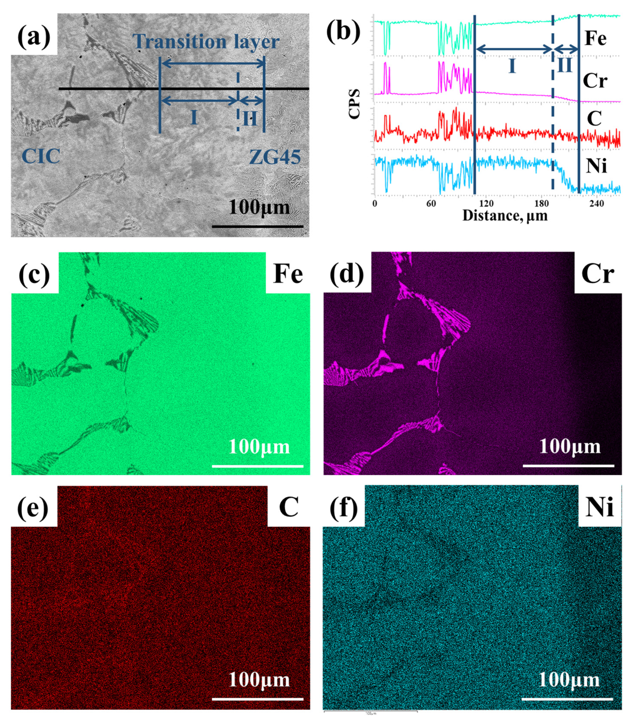
The thickness of the CICs can reach about 7 mm. A transition layer composed of pearlite was generated with a thickness of about 110 μm between the CIC and the parent material, which can be explained by the calculated vertical section along the composition from Fe-0.45C (wt.%) to Fe-20Cr-2C (wt.%). Diffusion occurs mainly in the transition layer, considering the obvious variations of elemental contents.
(4)
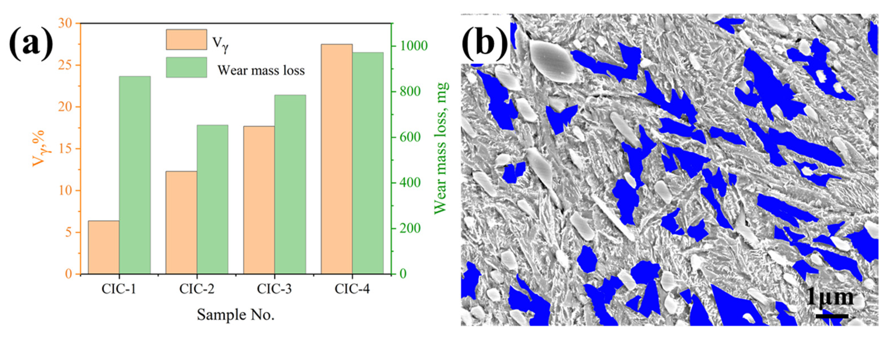
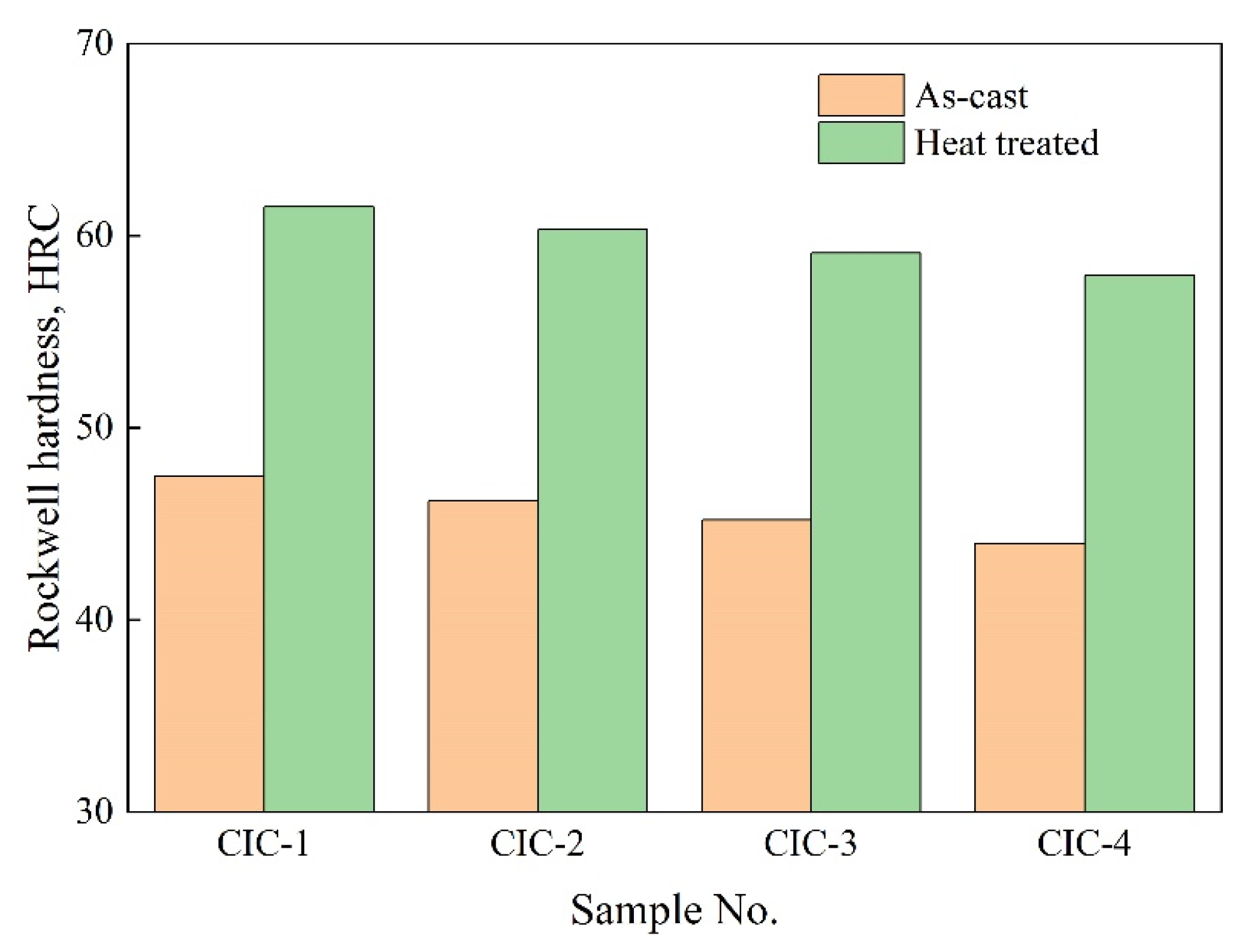
After the critical and subcritical heat treatment, the matrix of the CICs transformed to martensite, resulting in a significant increase in the Rockwell hardness. With the increase in Ni content, the proportion of the retained austenite in the CICs increased from 6.4 vol.% to 27.5 vol.%, while the hardness decreased from 61.5 HRC to 57.9 HRC.
(5)
The sample CIC-2 has the least mass loss after the impact wear test, which is consistent with the shallowest spalling pits indicated in the worn cross section. The best impact wear resistance performance can be achieved by an adequate combination of hardness and toughness resulting from an optimal proportion of the austenite in the CIC.

Author Contributions

Conceptualization, C.C., S.W. and T.J.; Methodology, C.C., S.W., F.M. and L.X.; Simulation, C.C., T.W. and M.X.; Investigation, C.C., T.W., W.L. and X.W.; Writing—Original Draft Preparation, C.C., T.W. and W.L.; Writing—Review and Editing, S.W., F.M., M.X. and T.J.; Visualization, L.X., X.W. and C.Z.; Funding Acquisition, C.C. and S.W. All authors have read and agreed to the published version of the manuscript.

Funding

This research was funded by the National Natural Science Foundation of China (No. 51901070), the Key Scientific and Technological Project of Henan Province (No. 222102230059) and the Open Fund of National Joint Engineering Research Center for abrasion control and molding of metal materials (Nos. HKDNM202108 and HKDNM2019019).

Institutional Review Board Statement

Not applicable.

Informed Consent Statement

Not applicable.

Data Availability Statement

The data presented in this study are available on request from the corresponding author.

Acknowledgments

The authors wish to take this opportunity to thank the support of Provincial and Ministerial Co-construction of Collaborative Innovation Center for Non-ferrous Metal New Materials and Advanced Processing Technology.

Conflicts of Interest

The authors declare no conflict of interest.

References

  1. Wei, S.Z.; Xu, L.J. Review on research progress of steel and iron wear-resistant materials. Acta Metall. Sin. 2020, 56, 523–538. [Google Scholar]
  2. Jia, R.; Liu, S.; Luo, Z.; Ning, J.; Wang, H.; Luo, T.; Zhu, Y.; Yuan, X.; Wang, Z. Microstructure and Wear Resistance of WC and High Chromium Cast Iron Hardfacing Layers. Coatings 2020, 10, 852. [Google Scholar] [CrossRef]
  3. Chen, C.; Dong, Y.; Hu, C.; Du, Y.; Wei, S.; Long, J.; Wang, C.; Xiao, L.; Mao, F. Fabrication of gradient cemented carbide with Ni3Al binder: Simulations and experiments. Ceram. Int. 2022, 48, 12756–12763. [Google Scholar] [CrossRef]
  4. Lou, M.; Chen, X.; Xu, K.; Deng, Z.; Chen, L.; Lv, J.; Chang, K.; Wang, L. Temperature-induced wear transition in ceramic-metal composites. Acta Mater. 2021, 205, 116545. [Google Scholar] [CrossRef]
  5. Nayak, U.P.; Suárez, S.; Pesnel, V.; Mücklich, F.; Guitar, M.A. Load dependent microstructural evolution in an as-cast 26% Cr high chromium cast iron during unlubricated sliding. Friction 2022, 10, 1258–1275. [Google Scholar] [CrossRef]
  6. Lu, K.; Zhu, J.; Guo, D.; Yang, M.; Sun, H.; Wang, Z.; Hui, X.; Wu, Y. Microstructures, Corrosion Resistance and Wear Resistance of High-Entropy Alloys Coatings with Various Compositions Prepared by Laser Cladding: A Review. Coatings 2022, 12, 1023. [Google Scholar] [CrossRef]
  7. Matikainen, V.; Rubio Peregrina, S.; Ojala, N.; Koivuluoto, H.; Schubert, J.; Houdková, Š.; Vuoristo, P. Erosion wear performance of WC-10Co4Cr and Cr3C2-25NiCr coatings sprayed with high-velocity thermal spray processes. Surf. Coat. Technol. 2019, 370, 196–212. [Google Scholar] [CrossRef]
  8. Morozow, D.; Barlak, M.; Werner, Z.; Pisarek, M.; Konarski, P.; Zagórski, J.; Rucki, M.; Chałko, L.; Łagodziński, M.; Narojczyk, J.; et al. Wear Resistance Improvement of Cemented Tungsten Carbide Deep-Hole Drills after Ion Implantation. Materials 2021, 14, 239. [Google Scholar] [CrossRef]
  9. Sawant, M.S.; Jain, N.K. Investigations on wear characteristics of Stellite coating by micro-plasma transferred arc powder deposition process. Wear 2017, 378, 155–164. [Google Scholar] [CrossRef]
  10. Wang, Y.; Lu, D.; Ma, W.; Zhang, Y. Compression and Wear Properties of Ultrafine Al2O3p/Iron Composites Prepared by Cast Infiltration. JOM 2022, 74, 1878–1885. [Google Scholar] [CrossRef]
  11. Xu, L.; Wang, F.; Zhou, Y.; Wang, X.; Chen, C.; Wei, S. Fabrication and wear property of in-situ micro-nano dual-scale vanadium carbide ceramics strengthened wear-resistant composite layers. Ceram. Int. 2021, 47, 953–964. [Google Scholar] [CrossRef]
  12. Lavecchia, F.; Pellegrini, A.; Galantucci, L.M. Comparative study on the properties of 17-4 PH stainless steel parts made by metal fused filament fabrication process and atomic diffusion additive manufacturing. Rapid Prototyp. J. 2022. ahead-of-print. [Google Scholar] [CrossRef]
  13. Khorasani, M.; Ghasemi, A.; Leary, M.; Sharabian, E.; Cordova, L.; Gibson, I.; Downing, D.; Bateman, S.; Brandt, M.; Rolfe, B. The effect of absorption ratio on meltpool features in laser-based powder bed fusion of IN718. Opt. Laser Technol. 2022, 153, 108263. [Google Scholar] [CrossRef]
  14. Mussi, E.; Servi, M.; Facchini, F.; Furferi, R.; Volpe, Y. Assessment and treatment of pectus deformities: A review of reverse engineering and 3D printing techniques. Rapid Prototyp. J. 2022. ahead-of-print. [Google Scholar] [CrossRef]
  15. Panahizadeh, V.; Ghasemi, A.H.; Dadgar Asl, Y.; Davoudi, M. Optimization of LB-PBF process parameters to achieve best relative density and surface roughness for Ti6Al4V samples: Using NSGA-II algorithm. Rapid Prototyp. J. 2022. ahead-of-print. [Google Scholar] [CrossRef]
  16. Fischer, S.F.; Muschna, S.; Bührig-Polaczek, A.; Bünck, M. In-situ surface hardening of cast iron by surface layer metallurgy. Mater. Sci. Eng. A 2014, 615, 61–69. [Google Scholar] [CrossRef]
  17. Wang, Y.; Zhang, X.; Zeng, G.; Li, F. In situ production of Fe–VC and Fe–TiC surface composites by cast-sintering. Compos. Part A Appl. Sci. Manuf. 2001, 32, 281–286. [Google Scholar] [CrossRef]
  18. Jing, W.; Wang, Y. In-situ production of Fe–TiC composite. Mater. Lett. 2007, 61, 4393–4395. [Google Scholar] [CrossRef]
  19. Ye, F.; Hojamberdiev, M.; Xu, Y.; Zhong, L.; Zhao, N.; Li, Y.; Huang, X. Microstructure, microhardness and wear resistance of VCp/Fe surface composites fabricated in situ. Appl. Surf. Sci. 2013, 280, 297–303. [Google Scholar] [CrossRef]
  20. Guitar, M.A.; Suárez, S.; Prat, O.; Duarte Guigou, M.; Gari, V.; Pereira, G.; Mücklich, F. High Chromium Cast Irons: Destabilized-Subcritical Secondary Carbide Precipitation and Its Effect on Hardness and Wear Properties. J. Mater. Eng. Perform. 2018, 27, 3877–3885. [Google Scholar] [CrossRef]
  21. Ibrahim, M.M.; El-Hadad, S.; Mourad, M. Influence of Niobium Content on the Mechanical Properties and Abrasion Wear Resistance of Heat-Treated High-Chromium Cast Iron. Int. J. Met. 2021, 15, 500–509. [Google Scholar] [CrossRef]
  22. Li, Z.; Jiang, Y.; Rong, Z.; Lu, D.; Zhou, R. Dry three-body abrasive wear behavior of WC reinforced iron matrix surface composites produced by V-EPC infiltration casting process. Wear 2007, 262, 649–654. [Google Scholar] [CrossRef]
  23. Zheng, B.; Li, W.; Tu, X.; Xu, F.; Liu, K.; Song, S. Effect of titanium binder addition on the interface structure and three-body abrasive wear behavior of ZTA ceramic particles-reinforced high chromium cast iron. Ceram. Int. 2020, 46, 13798–13806. [Google Scholar] [CrossRef]
  24. Zhang, Q.; Chen, C.; Zhang, C.; Ma, J.; Zhang, C.; Mao, F. Effect of Boron on Microstructure and Properties of Casting Infiltration Layer of High Chromium Cast Iron. Mater. Rep. 2022, 36, 20110229-7. [Google Scholar] [CrossRef]
  25. Wang, F.; Xu, L.; Wei, S.; Wang, X.; Chen, C.; Zhou, Y. Preparation and wear properties of high-vanadium alloy composite layer. Friction 2022, 10, 1166–1179. [Google Scholar] [CrossRef]
  26. Qin, Y.; Wang, Y.; Miao, W.; Yang, P.; Fu, D.; Fan, L.; Chen, H. Interface modification and impact abrasive wear behavior of ZTA particle-reinforced iron-matrix composite. Wear 2022, 490, 204205. [Google Scholar] [CrossRef]
  27. Krbata, M.; Eckert, M.; Majerik, J.; Barenyi, I. Wear Behaviour of High Strength Tool Steel 90MnCrV8 in Contact with Si3N4. Metals 2020, 10, 756. [Google Scholar] [CrossRef]
  28. Fan, X.H.; He, L.; Zhou, Q.D. A study of high chromium cast iron on abrasion resistance and impact fatigue resistance. Wear 1990, 138, 47–60. [Google Scholar] [CrossRef]
  29. Jun-Tong, X.; Qing-De, Z.; Shi-Hui, L.; Guang-Shun, S. Influence of retained austenite on the wear resistance of high chromium cast iron under various impact loads. Wear 1993, 162, 83–88. [Google Scholar] [CrossRef]
  30. Inthidech, S.; Sricharoenchai, P.; Matsubara, Y. Effect of Alloying Elements on Heat Treatment Behavior of Hypoeutectic High Chromium Cast Iron. Mater. Trans. 2006, 47, 72–81. [Google Scholar] [CrossRef]
  31. Du, Y.; Liu, S.; Zhang, L.; Xu, H.; Zhao, D.; Wang, A.; Zhou, L. An overview on phase equilibria and thermodynamic modeling in multicomponent Al alloys: Focusing on the Al–Cu–Fe–Mg–Mn–Ni–Si–Zn system. Calphad 2011, 35, 427–445. [Google Scholar] [CrossRef]
  32. Liu, W.; Chen, C.; Tang, Y.; Long, Q.; Wei, S.; Zhang, G.; Mao, F.; Jiang, Q.; Zhang, T.; Liu, M. Thermodynamic evaluation and investigation of solidification microstructure in the Fe–Cr–Ni–C system. Calphad 2020, 69, 101763. [Google Scholar] [CrossRef]
  33. Chen, Q.; Sundman, B. Computation of Partial Equilibrium Solidification with Complete Interstitial and Negligible Substitutional Solute Back Diffusion. Mater. Trans. 2002, 43, 551–559. [Google Scholar] [CrossRef]
  34. Chen, C.; Wang, T.; Wei, S.; Liu, W.; Zhang, G.; Tang, Y.; Pan, K.; You, L.; Xu, L.; Jiang, T. Effect of Cr Content on the Microstructure of Casting Infiltration Layers: Simulations and Experiments. Crystals 2022, 12, 1022. [Google Scholar] [CrossRef]
Figure 1. Schematic diagram of the sand mold used for casting infiltration.
Coatings 12 01313 g001
Figure 2. Illustration diagram of the impact wear tester.
Coatings 12 01313 g002
Figure 3. Calculated solidification paths of the CICs according to the modified Scheil–Gulliver simulation: (a) CIC-1; (b) CIC-2; (c) CIC-3; (d) CIC-4.
Coatings 12 01313 g003
Figure 4. Optical images of the microstructure of the CICs: (a) CIC-1; (b) CIC-2; (c) CIC-3; (d) CIC-4.
Coatings 12 01313 g004
Figure 5. Enlarged SEM image and the EDS analysis of the eutectic carbide for CIC-3. (a) SEM image; (b) EDS analysis of point A.
Coatings 12 01313 g005
Figure 6. (a) Macrograph of as-cast CIC-3; (b) SEM micrograph of as-cast CIC-3 at the interface; (c) SEM micrograph of region A in (b); (d) calculated vertical section along the compositions from Fe–0.45C (wt.%) to Fe–20Cr–2C (wt.%).
Coatings 12 01313 g006
Figure 7. Interface of the sample CIC-3: (a) SEM image; (b) EDS line scanning result of the black line in (a); EDS mapping scanning results for (c) Fe, (d) Cr, (e) C and (f) Ni.
Coatings 12 01313 g007
Figure 8. SEM images of the samples with different Ni content in CICs after heat treatment: (a,b) CIC-1; (c,d) CIC-2; (e,f) CIC-3; (g,h) CIC-4.
Coatings 12 01313 g008
Figure 9. SEM images of the matrix of CICs after heat treatment: (a) CIC-1; (b) CIC-2; (c) CIC-3; (d) CIC-4.
Coatings 12 01313 g009
Figure 10. (a) The amount of the retained austenite in the CICs after heat treatment, along with the wear mass loss after the impact wear test; (b) a graphically treated image used in ImageJ software marking the retained austenite for CIC-2.
Coatings 12 01313 g010
Figure 11. Rockwell hardnesses of the as-cast and heat-treated CICs.
Coatings 12 01313 g011
Figure 12. SEM images of the worn cross section after impact wear: (a) CIC-1; (b) CIC-2; (c) CIC-3; (d) CIC-4.
Coatings 12 01313 g012
Figure 13. SEM images of the worn surface morphologies after impact wear: (a) CIC-2; (b) CIC-4.
Coatings 12 01313 g013
Table 1. Alloy compositions designed for casting infiltration agents and determined in the obtained CICs (wt.%).
DesignationAlloy Compositions of the AgentAlloy Compositions of the CICs
CCrNiFeCCrNiFe
CIC-16700Bal.2.0120.330Bal.
CIC-26705Bal.2.0120.251.53Bal.
CIC-367010Bal.2.1119.052.82Bal.
CIC-467015Bal.1.9819.015.53Bal.
Table 2. Experimental and calculated volume fractions of M7C3.
TypeVolume Fractions of M7C3 (vol.%)
CIC-1CIC-2CIC-3CIC-4
Experimental values19.9518.6217.1317.68
Calculated values17.8018.0218.3517.91
Publisher’s Note: MDPI stays neutral with regard to jurisdictional claims in published maps and institutional affiliations.

