Article

Thermal Analysis of Mullite Coated Piston Used in a Diesel Engine

1
School of Naval Architecture, Ocean and Energy Power Engineering, Wuhan University of Technology, Wuhan 430063, China
2
School of Naval Architecture and Navigation, Wuhan Technical College of Communications, Wuhan 430065, China
*
Author to whom correspondence should be addressed.
Coatings 2022, 12(9), 1302; https://doi.org/10.3390/coatings12091302
Submission received: 26 July 2022 / Revised: 31 August 2022 / Accepted: 2 September 2022 / Published: 5 September 2022

Abstract

:
Due to special working conditions, diesel engines often need to run stably for a long time at high power operating conditions. As the core of diesel engine moving parts, the piston needs to be exposed to high temperature for a long time. Based on the problem of excessive piston temperature at the maximum power point of a certain type of diesel engine, this paper discussed the protective effect of using different thicknesses of Mullite thermal barrier coating on the top surface of the piston, by using the method of hardness plug temperature measurement and three-dimensional simulation. When the thickness of the ceramic coating was increased from 0.2 to 0.7 mm, the maximum temperature of the piston seat decreased from 358.6 to 338.9 °C. This showed that the use of Mullite thermal barrier coating could reduce the working temperature of the aluminum alloy piston at the maximum load operating point, and greatly improve the reliability of engine components.

1. Introduction

As a kind of self-ignition engine, diesel engines have high temperature and pressure in the cylinder. This leads to the harsh working conditions of some important components. Among them, the piston is always in contact with high-temperature gas and undertakes a high heat load. At the same time, diesel engines are developing in the direction of high-power density and low fuel consumption because of the continuous improvement of engine performance requirements. For diesel engines, reducing heat loss can effectively improve thermal efficiency. However, lower thermal loss means higher temperature and pressure in the combustion chamber, which makes the piston and other components bear higher thermal loads [1]. The larger thermal load can easily cause piston failure, so it is important to reduce the thermal load of pistons and other components while improving thermal efficiency.
Many studies have shown that the TBC system can effectively reduce the heat load of substrate materials and increase thermal efficiency [2,3,4]. Coating of the diesel engine piston is a common application for the TBC system, and it can insulate the piston crown. Then, the heat lost through the piston, could effectively reduce the piston heat load. The coating is a ceramic-based material with low thermal conductivity and high strength, and can withstand higher temperatures than the piston substrate. The positive impact of coating is also reflected in the reduction of fuel consumption and emissions [5].
The traditional double-layer structure thermal barrier coating (TBC) usually consists of a ceramic topcoat and a metallic bond coat. The bond coat material is an intermetallic alloy that aids in the better adhesion of the ceramic topcoat and substrate, due to its moderate expansion coefficient. Oxidation resistance at high temperatures effectively reduces the internal stress between the ceramic coating and the substrate [6,7,8]. The ceramic topcoat has a much lower thermal conductivity than the substrate, so it can effectively separate the heat in the combustion chamber. Therefore, the temperature of the piston substrate is significantly reduced, which improves the reliability of the piston. At the same time, increase in the chamber temperature improves its thermal efficiency.
YSZ coating is widely used in the leaves of gas turbines, due to its excellent performance, and many researchers have applied the YSZ coating on the diesel engine [9,10,11]. However, compared with the gas turbine, the repeated thermal cycling in a diesel engine makes the YSZ coating more likely to crack, and then accelerates the oxidation of the bond coat, which eventually causes the coating to fail [12]. Therefore, it is important to find a coating material which is suitable for diesel engines. Scholars have found that Mullite coating has better performance in diesel engines. K. Kokini [13] studied the stress relaxation of Zirconia coating and Mullite coating. Results showed that the stress relaxation behavior of Zirconia coating causes stretch stress during cooling. On the contrary, Mullite coating could significantly reduce the stress relaxation behavior, so that the stress does not develop during cooling, which effectively reduces the possibility of surface cracks. P Ramaswamy [14] evaluated the durability of YPSZ coatings and Mullite coating. After 500 h of engine test, the results showed that Mullite coating has stronger resistance to microcracking. T. M. Yonushonis [15] evaluated the lifetime of different coatings through single-cylinder engine tests. The test results showed that the durability of Mullite coating is significantly better than Zirconia coating. Kanwal, Sonup [16] investigated the corrosion behavior of Mullite coating. In this study, the coating had no cracks after 20 cycles of cyclic oxidation at 700 °C. Ramaswamy, P [17] conducted thermal shock tests on Mullite coating. The coating was intact when shocked from 1000 °C. By observing scanning electron microscopy pictures, it was found that the bond coat had no further oxidization, which indicated that Mullite coating is suitable for working conditions of repeated thermal cycling in a diesel engine.
This article selected Mullite coating as more suitable for diesel engines. Mullite coating not only has good thermal insulation, but also has higher reliability than YSZ coating. Figure 1 shows the scanning electron microscope picture of Mullite coating and 8YSZ coating. Compared with 8YSZ coating, Mullite coating had less pores. In previous research, the relationship between the thickness of Mullite coating and temperature distribution has had little research. However, this work is crucial to the choice of thickness and the development of coatings. Therefore, a static thermal analysis was performed on conventional piston and uncoated piston through ANSYS. As shown in Figure 2, the piston model used in the simulation was an aluminum alloy diesel piston. In this study, the temperature distributions were obtained and studied when changing the thickness of Mullite coating.

2. Methodology

ANSYS Workbench was used to perform steady state thermal analysis. The steps of the piston analysis follow.

2.1. Modeling

Since it is directly impacted by high-temperature gas, the piston needs to have high strength and rigidity. The traditional cast iron piston has high strength and rigidity, but it cannot meet lightweight design requirements because of its high density. The piston used in this study was made of aluminum alloy, which has high strength and lower density. The material of the piston ring was cast iron. It can be seen from Figure 1 that the piston had evenly arranged temp-plugs, and these temp-plugs measured the temperature value of the piston at the torque point. Due to the symmetry of the piston, the model can be simplified to a quarter. At the same time, the small structure and the chamfer that had less influence on the analysis were ignored. The simplified model is shown in Figure 3, and the names of each area are showed in Table 1. The piston model with the thickness of the coating at 0.2 mm is shown in Figure 4.

2.2. Material Properties

TBC is a material with a lower thermal conductivity, which can separate a large amount of heat, thereby reducing the piston heat load. Mullite has a lot of potential as a TBC material. It has low density, low thermal conductivity and high thermal stability. It is suitable for diesel pistons [14]. The coating thickness of Mullite was 0.2, 0.3, 0.5, 0.7, 0.9 mm. The bond coat was high-temperature alloy, which, in this study, was NiCrAlY. The coating thickness of NiCrAlY was 0.1 mm. Its main function is to resist high temperature oxidation and closely combine with surface ceramic coatings. All the properties of Mullite and NiCrAlY are shown in Table 2.

2.3. Meshing

The grid was divided after defining the attributes of each material. The number of model grids were determined by grid size. Too small a size causes excessive grid quantity to increase the calculation workload while excessive grid size leads to poor grid mass and reduces the accuracy of calculation. A reasonable grid size can form a grid quality that meets the requirements for calculation, so the grid of the ceramic topcoat and bond coat in this study were refined. The grid model with a thickness of 0.2 mm in coating is presented in Figure 4. A total of 15,203,305 elements and 3,708,552 nodes were used.

2.4. Boundary Conditions
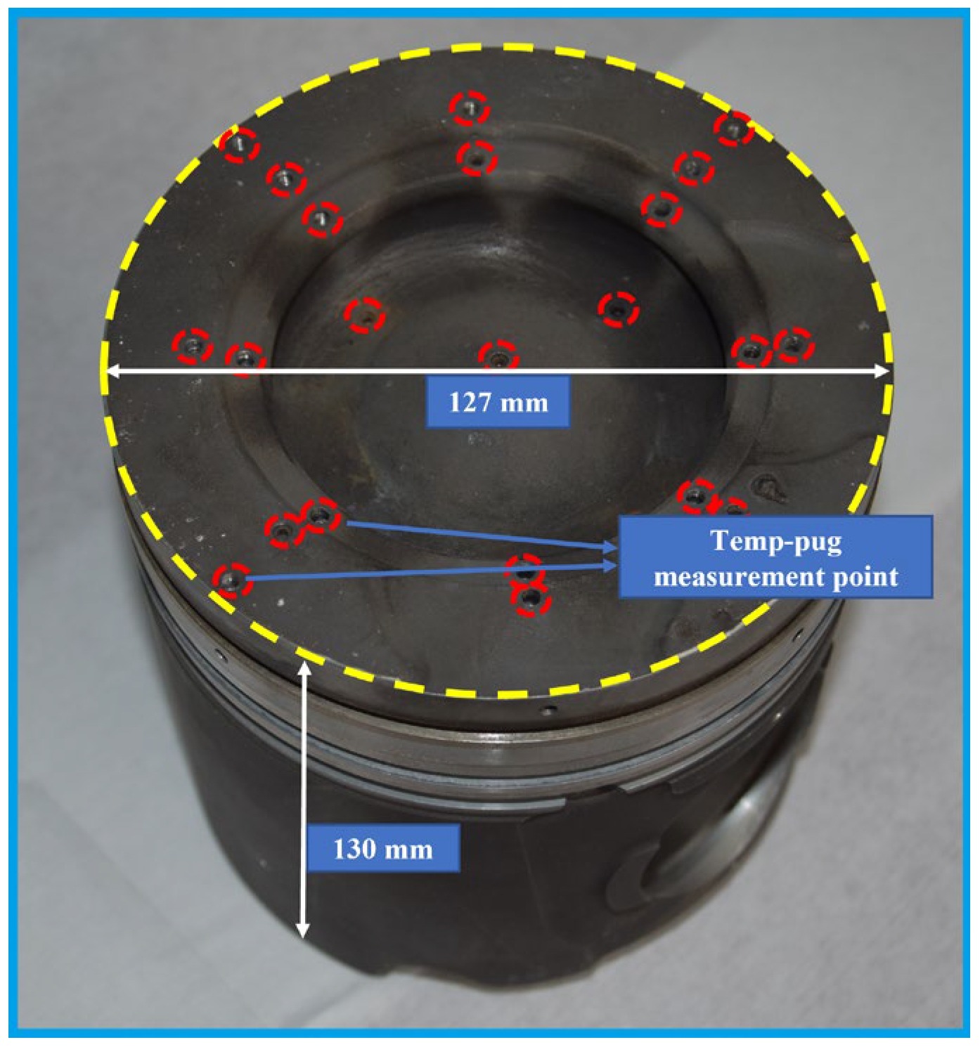
The actual piston heat conduction is very complicated, so the thermal conductivity of the piston was simplified in this study. The simplified thermal boundary included: gas and piston top surface, piston and cooling fuel cavity, piston and cylinder liner, the bottom of the piston and splashing oil. According to the experience formula and actual measurement values, the surface thermal boundary conditions (as shown in Table 3) were calculated.
Among them, the convection coefficient and gas temperature of the piston top surface used the following two formulae [21]:
h m = 0 4 π h g d φ 4 π
T m = 0 4 π h g T g d φ 0 4 π h g d φ
where hg is the transient convection coefficient, Tg is the transient temperature of the combustion gas, hm is the equivalent convection coefficient, Tm is the equivalent temperature of the combustion gas, and φ is the crankshaft corner.
The gas temperature was calculated to be 700 °C, and the corresponding convection coefficient was 1151 W/m2 °C. The heat transfer process between the piston and the cylinder can be simplified into a thermal resistance network of multi-layer flat walls. The temperature of the fire shore was calculated to be 120 °C with a convection coefficient of 266 W/m2 °C. The temperatures of the upper, middle, and lower parts of the first ring were estimated to be 120, 115, and 110 °C, and the convection coefficients were 359, 201, 359 W/m2 °C, respectively. The temperature of the second ring was calculated to be 93 °C with a convection coefficient of 428 W/m2 °C. The temperature of the skirt was calculated to be 93 °C with a convection coefficient of 425 W/m2 °C. The bottom of the piston was cooled by the oil in the crankcase, and the convection coefficient of this part was very complex. So, it was assumed that the heat lost from the bottom of the piston was equal to the absorbed heat of oil. Then, the convection coefficient of this part was calculated to be 500 W/m2 °C. The surface temperature was oil temperature 120 °C. The oil in the cooling oil cavity was sprayed in through the oil hole, so the heat stress coefficient could be estimated through the following formula:
cq m Δ T oil = hA Δ T wall
where qm is the quality flow of the nozzle, c is the specific heat of the oil, A is the main heat exchange area of the inner cavity, h is the heat convection coefficient, and ΔToil and ΔTwall are the temperature variations of motor oil and inner wall surfaces, respectively. The temperature of the cooling oil cavity was calculated to be 120 °C with a convection coefficient of 1800 W/m2 °C.

2.5. Validation

It was important to check the authenticity of the piston model and that the thermal boundary conditions were correct, as this determines the authenticity of subsequent simulation results. So, this article compared the simulation temperature value of the coating piston with the experimental value. The temp-plug method was used to measure the temperature value by using metal materials that produce permanent hardness after heating, making it very suitable for a long-term stable system. In this study, the engine ran under the condition of the torque point because the thermal load of the piston was high under this condition. After the test, the temp-plugs were taken out and their hardness measured. Then the experimental value was obtained by the HV-T curve (see Figure 5).

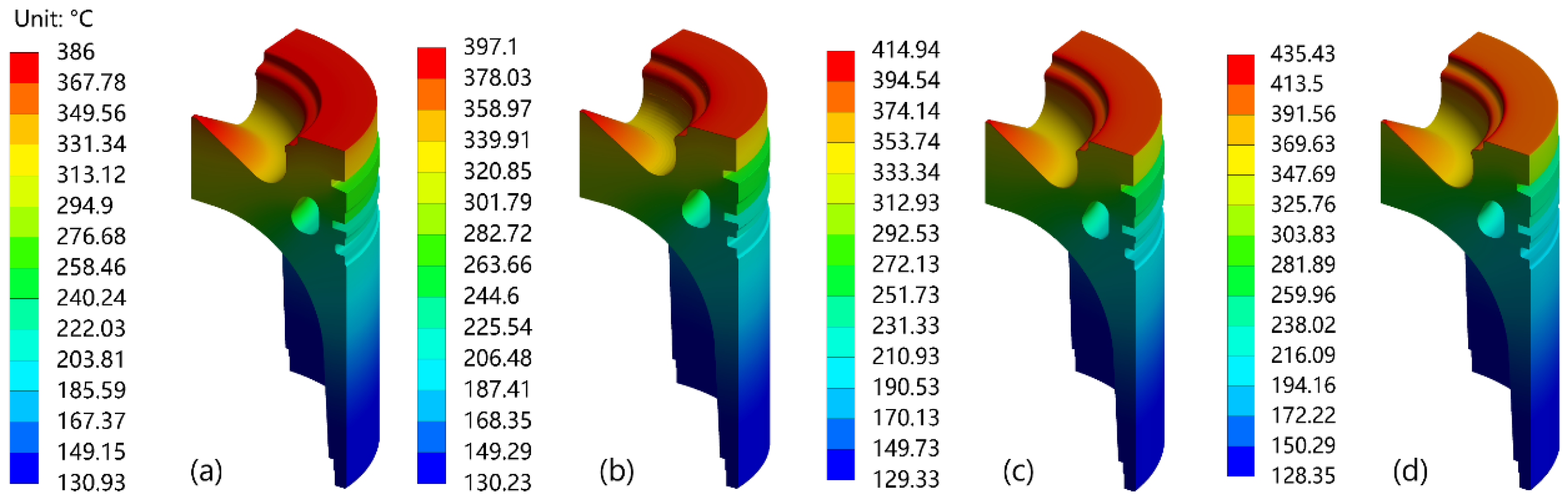
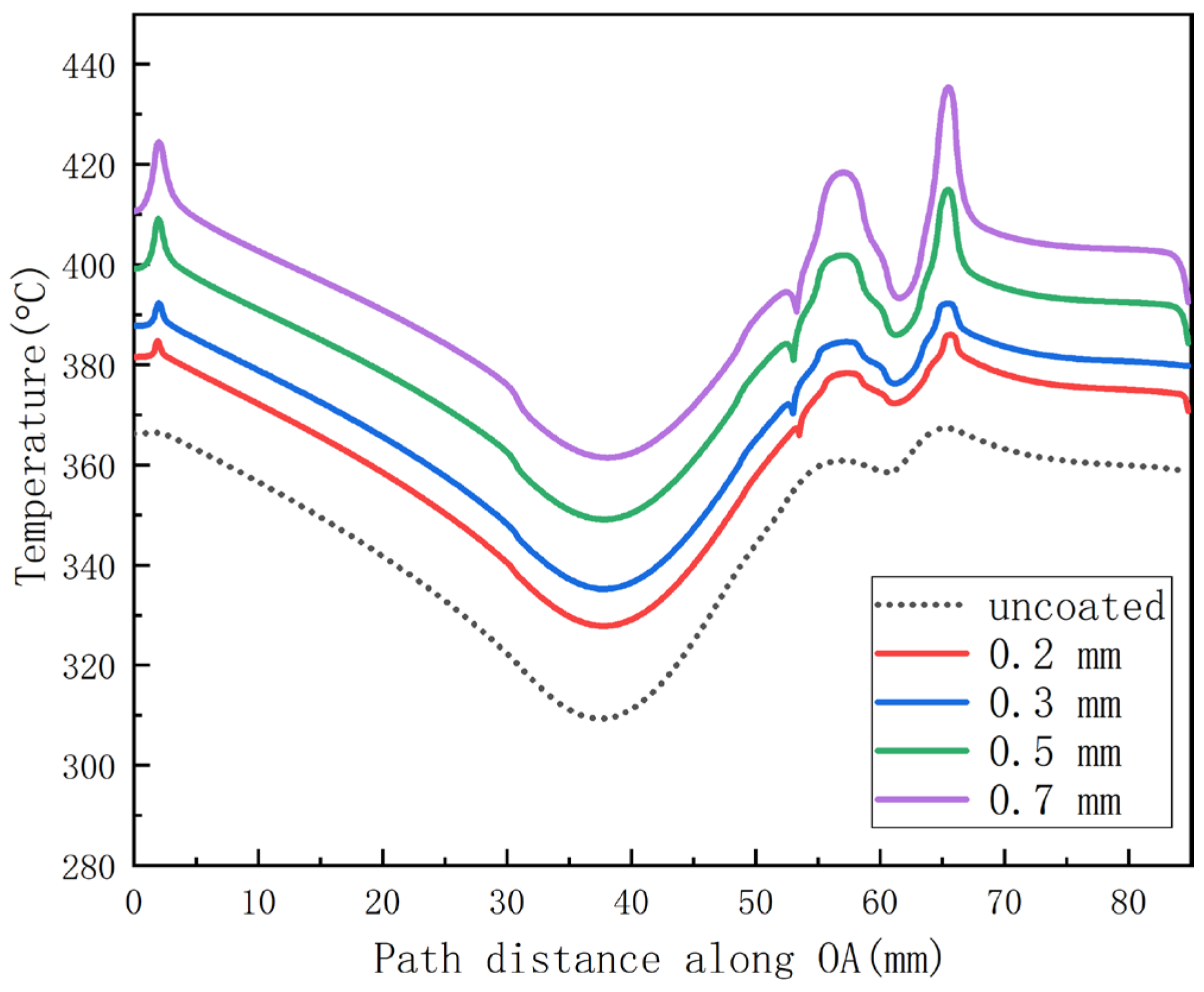
3. Results and Discussion

This article has systematically discussed the results of a static thermal analysis of a conventional piston and coating piston. Figure 6 shows the temperature distribution of the conventional piston. After analysis, the maximum temperature value was 367.34 °C, obtained at the piston’s throat mouth, and the minimum was 131.88 °C, obtained at the bottom of the piston.
Figure 7a–d shows the temperature distributions of the coated piston with the topcoat thicknesses of 0.2, 0.3, 0.5 and 0.7 mm. Results showed that the values of maximum temperature on the topcoat surface were 386, 397.1, 414.94 and 435.43 °C, respectively. As expected, the temperature of the topcoat surface increased with the thickness of the coating. This was because the thermal conductivity of ceramic materials was lower than that of aluminum alloy, which reduced the heat loss.
Similarly, Figure 8a–d shows the temperature distribution of substrate surface for the coated pistons. The results showed that the values of maximum temperature at the piston’s substrate were 358.61, 353.49, 346.29 and 338.86 °C from thicknesses of 0.2, 0.3, 0.5, and 0.7 mm ceramic coating. It was a satisfactory result that the temperature of the substrate decreased with the thickness of the coating, because the lower temperature could improve the reliability of the piston.
Figure 3 displays a path along the line OA. The relationship between the temperature of the topcoat surface and the radial distance along the path for various thicknesses of coating and for the uncoated piston are presented in Figure 9. The maximum temperature variations for coating thicknesses of 0.2, 0.3, 0.5, and 0.7 mm were 5.1%, 8.1%, and 13.0%, and 18.5% for the topcoat surface.
The relationship between the temperature of the substrate surface and the radial distance along the path can be seen in Figure 10. The maximum temperature variations for coating thicknesses of 0.2, 0.3, 0.5, and 0.7 mm were 2.4%, 3.8%, and 5.7%, and 7.8% for the substrate surface. The decrease in the temperature of the piston substrate had a positive impact on the reliability of the piston.
The maximum temperature change of coating thickness on each surface is shown in Figure 11. The maximum temperature of TC increased with the thickness of the coating, while the maximum temperature of the BC and the substrate decreased with the thickness of the coating. The temperature changes of the substrate and the BC were very close, and the temperature difference between them was less than 7 °C. Smaller temperature difference meant lower thermal stress between TC and substrate, which increased the reliability of the coating.

4. Conclusions and Future Directions

According to the results of the hardness plug in this article, it can be seen that at the maximum working load of a certain type of diesel engine, the maximum temperature of the piston combustion chamber was around 370 °C, which was close to the failure temperature of aluminum alloy. Therefore, in order to explore the reliability of aluminum alloy pistons in long-term high load operations, this article established a three-dimensional model through the finite element method. Comparing the simulation results of the piston temperature field with the measured values of the temp-pug, it was found that the error was basically within 6%, indicating that the established piston model was accurate and reliable.
Based on the above-mentioned reliable three-dimensional piston model, this study established a piston model with a double-layer structured coating with different thicknesses. Mullite was used as the thermal barrier material to improve the ability of aluminum alloy pistons to resist high temperature loads.
The results of thermal analysis of pistons with different thicknesses of Mullite coatings showed that the surface temperature of the coated pistons was significantly higher than that of conventional pistons. The top surface temperature increased further as the coating thickness increased. Compared with the uncoated piston, the maximum temperature was increased by 5.1%, 8.1%, 13.0% and 18.5%, respectively. The temperature of the piston substrate after using the thermal barrier coating was significantly lower than that of the unsprayed piston substrate, so coating the piston with Mullite coating could effectively reduce the temperature of the piston substrate and improve its ability to withstand higher thermal loads.
In addition, although this paper only studied the influence of different thicknesses of Mullite coatings on the thermal insulation effect of the piston through the method of finite element simulation, we will use the atmospheric plasma spraying method to spray Mullite ceramic powder on the top surface of the piston, and use this on the diesel engine in future work. The relevant experimental equipment bench is under construction.

Author Contributions

Conceptualization, software and formal analysis, Z.S.; supervision and investigation, J.D.; supervision, Z.Q.; writing—original draft preparation and supervision, C.F.; methodology, S.Z.; investigation, Y.D.; investigation, K.Z. All authors have read and agreed to the published version of the manuscript.

Funding

The authors would like to thank the support of the Hubei Technological Innovation Special Fund (No. 2019BKJ002) and the Fundamental Research Funds for the Central Universities (No. 2018JL002).

Institutional Review Board Statement

Not applicable.

Informed Consent Statement

Not applicable.

Data Availability Statement

Data sharing not applicable.

Conflicts of Interest

The authors declare no conflict of interest.

Nomenclature

TBCThermal barrier coating
TCCeramic coating
BCBond coat
Al-SiAluminum–silicon
OACurved line of the piston crown surface (mm)
Temp-pugScrew made of metal material

References

  1. Buyukkaya, E.; Cerit, M. Thermal analysis of a ceramic coating diesel engine piston using 3-D finite element method. Surf. Coat. Technol. 2007, 202, 398–402. [Google Scholar]
  2. Wang, Y.; Ma, T.; Liu, L.; Yao, M. Numerical investigation of the effect of thermal barrier coating on combustion and emissions in a diesel engine. Appl. Therm. Eng. 2021, 186, 1359–4311. [Google Scholar]
  3. Cihan, Ö.; Temizer, İ.; Gök, M.G.; Karabaş, M. Investigation of the effect of rare earth doped La2Zr2O7 based thermal barrier coating on performance and combustion characteristics of DI diesel engine. Surf. Coat. Technol. 2020, 403, 126437. [Google Scholar]
  4. Caputo, S.; Millo, F.; Boccardo, G.; Piano, A.; Cifali, G.; Pesce, F.C. Numerical and experimental investigation of a piston thermal barrier coating for an automotive diesel engine application. Appl. Therm. Eng. 2019, 162, 114233. [Google Scholar]
  5. Vadivel, A.; Periyasamy, S. Experimental investigation of thermal barrier (8YSZ-MGO-TIO2) coated piston used in diesel engine. J. Appl. Fluid. Mech. 2020, 13, 1157–1165. [Google Scholar]
  6. Ng, H.W.; Gan, Z. A finite element analysis technique for predicting as-sprayed residual stresses generated by the plasma spray coating process. Finite Elem. Anal. Des. 2005, 41, 1235–1254. [Google Scholar]
  7. Cerit, M. Thermo mechanical analysis of a partially ceramic coated piston used in an SI engine. Surf. Coat. Technol. 2011, 205, 3499–3505. [Google Scholar]
  8. Buyukkaya, E. Thermal analysis of functionally graded coating AlSi alloy and steel pistons. Surf. Coat. Technol. 2008, 202, 3856–3865. [Google Scholar]
  9. Fei, C.G.; Qian, Z.Q.; Ren, J.; Zhou, X.J.; Zhu, S.W. Numerical and experimental research on thermal insulation performance of marine diesel engine piston based on YSZ thermal barrier coating. Coatings 2021, 11, 765. [Google Scholar]
  10. Thakare, J.G.; Pandey, C.; Mahapatra, M.M.; Mulik, R.S. Thermal barrier coatings—A state of the art review. Met. Mater. Int. 2021, 27, 1947–1968. [Google Scholar]
  11. Fei, C.G.; Qian, Z.Q.; Yang, Z.M.; Ren, J.; Zhu, S.W.; Yan, Y.A.; Shu, Z.H. Combustion and emission performance of isopropanol-butanol-ethanol (IBE) mixed with diesel fuel on marine diesel engine with nano YSZ thermal barrier coating. Energy 2022, 256, 124683. [Google Scholar] [CrossRef]
  12. Tamura, M.; Takahashi, M.; Ishii, J.; Suzuki, K.; Sato, M.; Shimomura, K. Multilayered thermal barrier coating for land-based gas turbines. J. Therm. Spray Technol. 1999, 8, 68–72. [Google Scholar] [CrossRef]
  13. Kokini, K.; Takeuchi, Y.R.; Choules, B.D. Surface thermal cracking of thermal barrier coatings owing to stress relaxation: Zirconia vs. mullite. Surf. Coat. Technol. 1996, 82, 77–82. [Google Scholar] [CrossRef]
  14. Ramaswamy, P.; Seetharamu, S.; Varma, K.B.; Raman, N.; Rao, K.J. Thermomechanical fatigue characterization of zirconia (8% Y2O3-ZrO2) and mullite thermal barrier coatings on diesel engine components: Effect of coatings on engine performance. Proc. Inst. Mech. Eng. Part C-J. Mech. Eng. Sci. 2000, 214, 729–741. [Google Scholar] [CrossRef]
  15. Yonushonis, T.M. Overview of thermal barrier coatings in diesel engines. J. Therm. Spray Technol. 1997, 6, 50–56. [Google Scholar] [CrossRef]
  16. Kanwal, S.; Thakare, J.G.; Pandey, C.; Singh, I.; Mahapatra, M.M. Characterization of slurry-based mullite coating deposited on P91 steel welds. J. Aust. Ceram. Soc. 2019, 55, 519–528. [Google Scholar] [CrossRef]
  17. Ramaswamy, P.; Seetharemu, S.; Varma, K.B.R.; Rao, K.J. Thermal shock characteristics of plasma sprayed mullite coatings. J. Therm. Spray Technol. 1998, 7, 497–504. [Google Scholar] [CrossRef]
  18. Zaini, M.S.F.; Mamat, A.M.I.; Saedon, J.B.; Adenan, M.S. Thermal barrier coating (TBC) of 8 yttria stabilized zirconia and mullite on medium carbon steel. J. Mech. Eng. 2020, 9, 13–23. [Google Scholar]
  19. Cao, X.Q.; Vassen, R.; Stoever, D. Ceramic materials for thermal barrier coatings. J. Eur. Ceram. Soc. 2003, 24, 1–10. [Google Scholar] [CrossRef]
  20. Zhou, C.G.; Wang, N.; Xu, H.B. Comparison of thermal cycling behavior of plasma-sprayed nanostructured and traditional thermal barrier coatings. Mater. Sci. Eng. A-Struct. Mater. Prop. Microstruct. Process. 2007, 452, 569–574. [Google Scholar] [CrossRef]
  21. Woschni, G. A Universally applicable equation for the instantaneous heat transfer coefficient in the internal combustion engine. SAE Trans. 1968, 76, 3065–3083. [Google Scholar]
Figure 1. The scanning electron microscope picture of cross-sections of the coatings: (a) Mullite coating, (b) 8YPSZ coating [18].
Coatings 12 01302 g001
Figure 2. The piston in this study.
Coatings 12 01302 g002
Figure 3. The simplified mode marked with path and boundary condition areas.
Coatings 12 01302 g003
Figure 4. The one-quarter piston model: (ac) the section view of refined mesh, (d) model structure diagram.
Coatings 12 01302 g004
Figure 5. HT-V Curve.
Coatings 12 01302 g005
Figure 6. (a) Temperature distribution of the uncoated piston (b) Errors of simulation and experimental values.
Coatings 12 01302 g006
Figure 7. Temperature distribution of topcoat surface for various coating thicknesses: (a) 0.2 mm, (b) 0.3 mm, (c) 0.5 mm, (d) 0.7 mm.
Coatings 12 01302 g007
Figure 8. Temperature distribution of substrate surface for various coating thicknesses: (a) 0.2 mm, (b) 0.3 mm, (c) 0.5 mm, (d) 0.7 mm.
Coatings 12 01302 g008
Figure 9. Topcoat surface temperature distribution with coating thickness along the path distance OA.
Coatings 12 01302 g009
Figure 10. Substrate surface temperature distribution with coating thickness along the path distance OA.
Coatings 12 01302 g010
Figure 11. Maximum temperature distribution with the thickness of the coating.
Coatings 12 01302 g011
Table 1. The name of each region.
RegionName
ACombustion chamber
BFire shore
CUpper of the first ring
DMiddle of the first ring
ELower of the first ring
FSecond ring
GPiston skirt
HCooling oil cavity
IThe bottom of the piston
Table 2. Material properties [19,20].
MaterialThermal
Conductivity
[W/m °C]
Thermal
Expansion
10−6 [1/°C]
Density [kg/m3]Specific Heat [J/kg °C]Young’s Modulus [GPa]Poisson’s Ratio
Piston (Al-Si alloy)155212700960900.3
Rings (cast iron)7912.273005002000.3
Mullite (ceramic topcoat)3.35.32750760300.25
NiCrAlY (bond coat)2317.578006021560.36
Table 3. Thermal boundary conditions.
RegionTemperature [°C]Heat Transfer Coefficient [W/m2 °C]
A7001151
B120266
C120359
D115201
E110359
F93428
G93425
H1201800
I120500
Publisher’s Note: MDPI stays neutral with regard to jurisdictional claims in published maps and institutional affiliations.

