1. Introduction
The component surfaces of industrial equipment in chemical and mechanical engineering are often exposed to permanent erosion, wear and corrosion processes due to mechanical and thermal stresses, interactions with solid particles or chemical reactions with an aggressive environment. Therefore, to extend the lifetime of components there is still the need for maintaining and repairing these surfaces. The restoration of a component’s proper state can be achieved by applying a protective metallic coating locally onto the damaged surfaces using a thermal spraying method. Thermal spraying is a deposition process to create homogenous or heterogeneous coatings on the surface of components with various sizes and geometries [
1,
2].
In this process, dispersed particles in a gas stream are heated up by an energy source (e.g., combustion or electric discharge). The particles are accelerated through a nozzle and focused towards a solid substrate. As a result, the impacted particles produce a dense coating [
3]. The main benefit of thermal spraying is the high flexibility of materials selection as the feedstock for deposition. Well-known and available thermal spraying techniques are the high velocity oxygen fuel spraying (HVOF), the detonation gun (D-gun), Wire Arc and cold spraying. The mentioned methods differ mainly in their process conditions (e.g., temperature, carrier gas, pressure, feedstock material). This study focuses on the cold gas-dynamic spraying (CGDS) process, in which the necessary binding energy is mainly achieved by the significant kinetic energy of the particles during impact.
In cold spraying, the material is sprayed at a temperature below its melting point, allowing temperature-sensitive materials to be utilized [
4,
5,
6]. Within the cold spray coating process, fineparticles are accelerated within a supersonic gas flow produced by a Laval nozzle to 600–1000 m/s and impact on the component surface [
7,
8]. At the moment of impact, the particle kinetic energy is converted into plastic deformation and heat of the particle and the substrate body. The coating specifications depend on transport phenomena in the multiphase flow for the acceleration of particles in the spray and the material deformation during the particle impact on the surface. The main benefits of CGDS are the creation of almost completely non-oxide coatings by using inert carrier gases, such as nitrogen or helium, and a deposition efficiency over 90% [
3]. The deposition efficiency is defined as the amount of attached material to the respective amount of powder mass flow during the cold spray process. These benefits consolidate the CGDS as a sustainable technology. Furthermore, the relatively low temperatures in contrast to other thermal spraying methods make CGDS more suitable to be used for mobile setups, for example, for repairing work.
Since the first patents of Alkhimov et al. [
9,
10] in the 1990s, the cold spray technology gained the interests of engineers and scientists in different fields. After their studies, cold spraying was further developed and new insights were obtained in the area of process optimization, applications and mechanisms for cold sprayed coatings [
11,
12]. Today, CGDS is used for surface functionalization and restoration for industrial applications in aerospace, automobile and civil engineering sectors [
12].
Due to the wide range of cold sprayed coatings in different industrial applications, there were many investigations to obtain insights of the underlying mechanisms. Mechanical interlocking, adiabatic shear instability (ASI), diffusion, recrystallization and localized melting are the most known bonding mechanisms in CGDS [
3,
13,
14,
15]. These mechanisms can depend on the process conditions and material characteristics (e.g., metals, oxides, ceramics, etc.). For ductile materials, ASI is assumed to be the dominant mechanism but recent studies challenge this viewpoint [
16,
17,
18]. Due to technical limitations, it is not possible to investigate the high velocity impact of a micron-sized particle on a surface that takes place within 100 ns. Therefore, numerical methods are used to obtain insights of the particle deformation.
A comprehensive description of the processes of particle acceleration, their impact on the surface and adhesion to the surface, as well as the prediction of the properties of the coating formed during cold spraying was presented in [
19]. In the work of Schmidt et al. [
20], the dynamics of the impact of a particle and the mechanism of its binding to the surface were studied. It also presents studies predicting the required conditions for the attachment of a particle to the surface. In our previous work [
21], a numerical model of the motion of especially fine solid particles (size below 10 µm) in the gas was developed and applied to optimize the nozzle design. In another work [
22], we studied the effect of the coatings with fine TiO
2 particles on the tribological behavior of 16MnCr5 steel chain pins created by the established cold spraying method for fine particles. Additionally, the surface modification by cold sprayed steel particles on steel substrates is described in the previous work [
23]. Champagne and Helfrich presented in their critical review of the repair of load-bearing components several successfully completed example cases on this topic [
24]. Careful preparation is necessary to repair a component effectively. The eroded part of the surface has to be cleaned to prevent contamination of the contact surface and a new metal coating can fill up the damaged parts of the surface [
25]. Since cold spray is a line-of-sight process, undercuts may have to be removed over a large area. The subsequent cold spray process then fills the damaged area completely. At the finishing step, the level difference between the original substrate and the filling material is reduced [
24]. Compact and mobile cold spray units are used for fast and safe repair of vehicles or helicopter bodies [
26].
The particle properties at the moment of impact have a significant influence on the resulting coating. Li et al. [
27] described the effect of the initial temperature of Cu particles and their adhesion to a Cu surface. Using the explicit finite element method (FEM) with the program ABAQUS, it was shown that a higher initial temperature is conducive to a higher maximum contact temperature after impact. A numerical study of the influence of particle properties on the deformation behavior during collisions in the cold spraying process was performed in the work of Li et al. [
28], which also provides an overview of the preheating of the substrate and particles [
29,
30,
31], particle oxidation, particle impact angle [
32] and prediction of the required critical velocity. Zhu et al. [
33] studied the penetration of a copper particle into the surface of aluminum alloys by numerical simulations with the FEM. The deformation was simulated by applying the Johnson–Cook plasticity and damage model that includes different thermal and mechanical material parameters. Their simulations showed that for small particle sizes of 1 µm, the kinetic energy is not high enough to provide successful bonding. However, due to the complex interactions in cold spraying, even small particles with a size of 1–10 µm can deposit on the surface, which is shown in experimental investigations [
4,
5,
23].
Studies on the numerical modelling of deposited particles via cold spraying are generally conducted for the impact on ideal flat surfaces. Real conditions, such as the availability of an oxide layer or surface roughness, are not taken into account. Such surface inhomogeneities can play a significant role and can affect the deposition efficiency or bonding strength.
Cold spray is used for the repair of parts that were damaged due to wear caused by mechanical or thermal stress during occupation [
34]. Damages on the equipment surface such as fracture or pits can be refurbished by spraying on the desired position with a powder of the same material. The defects or cracks on the surface can have sizes of few µm up to a few cm [
24]. These defects are present in the form of cavities on the surface and lead therefore to a defined surface roughness. In real cold spray experiments, surface defects can appear due to grit blasting [
35] prior to coating or due to an inhomogeneous coating layer structure during the process, especially for impact velocities that do not exceed the critical velocity [
20,
36]. Observations with scanning electron microscopy (SEM) show that the sizes of cracks can vary between 1 to 100 µm. This is in the range of the particle size distribution for the powder feedstock that is usually used in CGDS [
3]. It is assumed from observed investigations that the surface roughness of the substrate can enhance the mechanical interlocking of deposited particles to improve the bonding [
37,
38,
39].
The present study was performed to investigate the collision behavior of particles during cold spraying processes on substrates with microdefects, both made from AISI 1045 steel that is widely used for various areas of application. For this purpose, the impact of a single microparticle on a microdefect at the surface was investigated by numerical simulations with FEM. Different rectangular microdefect slot geometries and contact scenarios were studied and analyzed. The influence of particle size and defect size was studied as well.
2. Numerical Model and Simulation Parameters
Single particle impacts on a substrate that imitates a component surface were simulated with FEM. The Johnson–Cook model [
40] was applied to consider the occurring plastic deformation of contact partners during high-velocity collision at different strain rates and temperatures. The mechanical equivalent stress
that corresponds to the yield strength and failure strain
are given in Equations (1) and (2) respectively:
with
as the effective plastic strain and
as the dimensionless strain rate. The dimensionless strain rate is defined as
where
is the strain rate and
the reference strain rate.
,
,
,
and
are material parameters. Here, A is the quasi-steady state yield stress, B is the power law pre-exponential factor, C is the strain rate pre exponential factor, n describes the strain hardening exponent and m is the thermal softening exponent. These parameters can be determined experimentally with nanoindentation or split-Hopkins pressure bar [
41,
42].
According to the Johnson–Cook model, the failure strain depends on the dimensionless pressure-deviatoric stress ratio (where
is the pressure and
the von Mises stress), the dimensionless strain rate and the homologous temperature
:
to are failure parameters for the material.
The homologous temperature in Equation (3) describes the ratio of the material temperature
to its melting point
with the reference temperature
[
41]:
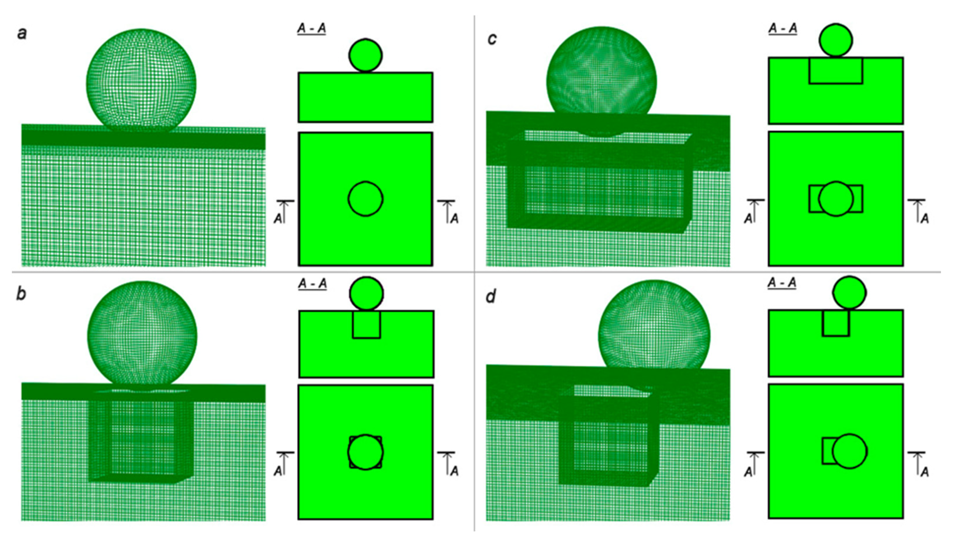
The simulations were performed for different contact scenarios. In the reference case (
Figure 1a), the normal impact of a spherical particle on a smooth surface (without surface roughness) of the substrate without damages was simulated. The other studied cases shown in
Figure 1b–d describe different scenarios of particle collisions on substrate with microdefects that was represented as a regular-shaped open cavity. Two different geometries of the microdefect were investigated: cube-shaped (
Figure 1b) and rectangular-shaped (
Figure 1c). In both cases, the particle collided in the center of the microdefect area. The central impact on the cube-shaped cavity (
Figure 1b) was compared to a non-central impact (
Figure 1d), where the contact point of the sphere was shifted to the edge of the defect.
The sizes of the particle and defect were varied, keeping the velocity of collision constant to investigate the influence of the particle/defect size at the constant mass-related kinetic energy. In the first simulation case, the substrate had a cube-shape with an edge length of 200 μm. The cube-shaped microdefect had a side length of 40 µm. The elongated cavity (
Figure 1c) had a height of 40 μm and a base area of 40 μm × 80 μm. The particle was modeled as a perfect sphere with a diameter of 50 µm. Therefore, at least one of the dimensions of the defect area was smaller than the particle diameter and the defect depth was 20% smaller than a particle. According to the chosen impact scenarios, the particle had a different number of initial contact points with the substrate: (a) one central contact, (b) four lateral contacts with edges of the microdefect, (c) two contacts with closer microdefect edges and (d) one contact with the edge of the defect. In the second simulation case, the particle size was reduced to 2.1 µm that corresponds to the experimentaly studied particle size in our previous work [
23]. This paticle size showed good adherence on the surface and can therefore be set as the minimum size that can attach to the surface. For this case, the ratio of the particle size to the defect size/shape was kept constant. The defect sizes were 1.7 μm × 1.7 μm × 1.7 µm (for cases b and d) and 3.4 μm × 1.7 μm × 1.7 µm (for case c), respectively.
The properties of the particle and the substrate material (both made from AISI 1045 steel) are summarized in
Table 1 [
43,
44]. The Johnson–Cook material parameters were derived from measurements on a split-Hopkins pressure bar facility conducted by Jaspers and Dautzenberg [
44]. The temperature dependence for the Young’s modulus, specific heat capacity, thermal conductivity, thermal expansion coefficient and fracture energy was taken into account according to the study of Kumar et al. [
43].
The impact velocity of the particle was 850 m/s. This impact velocity is above the estimated critical velocity according to Schmidt et al. [
20] and allows the investigation of particle deformation under succesful bonding conditions.
For the simulation, ABAQUS/Explicit [
45] was used, based on an explicit integration scheme and designed to calculate non-stationary dynamics, deformation and fracture during the fast collision process. Dynamic coupled thermal-stress analysis was selected. The calculated time interval of particle penetration into the substrate was determined by reducing the particle velocity in the vertical direction to zero. This interval was determined for each simulation case and divided into 5 steps, and each step was divided into 20 substeps. The nonlinear effects of large deformations were considered for all steps by switching on the “Nlgeom” setting. For the modeling of the interaction between particle and substrate, the “surface-to-surface” contact type with mechanical constraint formulation as “penalty contact method” and with sliding formulation as “finite sliding” was used. In contact property options, the normal and tangential behaviors were included. For the “normal behavior”, the contact pressure-overclosure relationships as “Hard” contact was used and for the “tangential behavior”, the friction formulation as “Penalty” with friction coefficient of 0.15 was set. The initial particle and substrate temperatures were assumed to be 20 °C. Additionally, it was specified that 90% of the kinetic energy is converted into heat. These assumptions are widely accepted in the literature [
16,
46]. The 3D mesh was generated with hexahedral grid elements of an edge length of 1 µm (
Figure 1).
3. Results
3.1. Case 1: Simulation of the Impact of 50 µm Particles
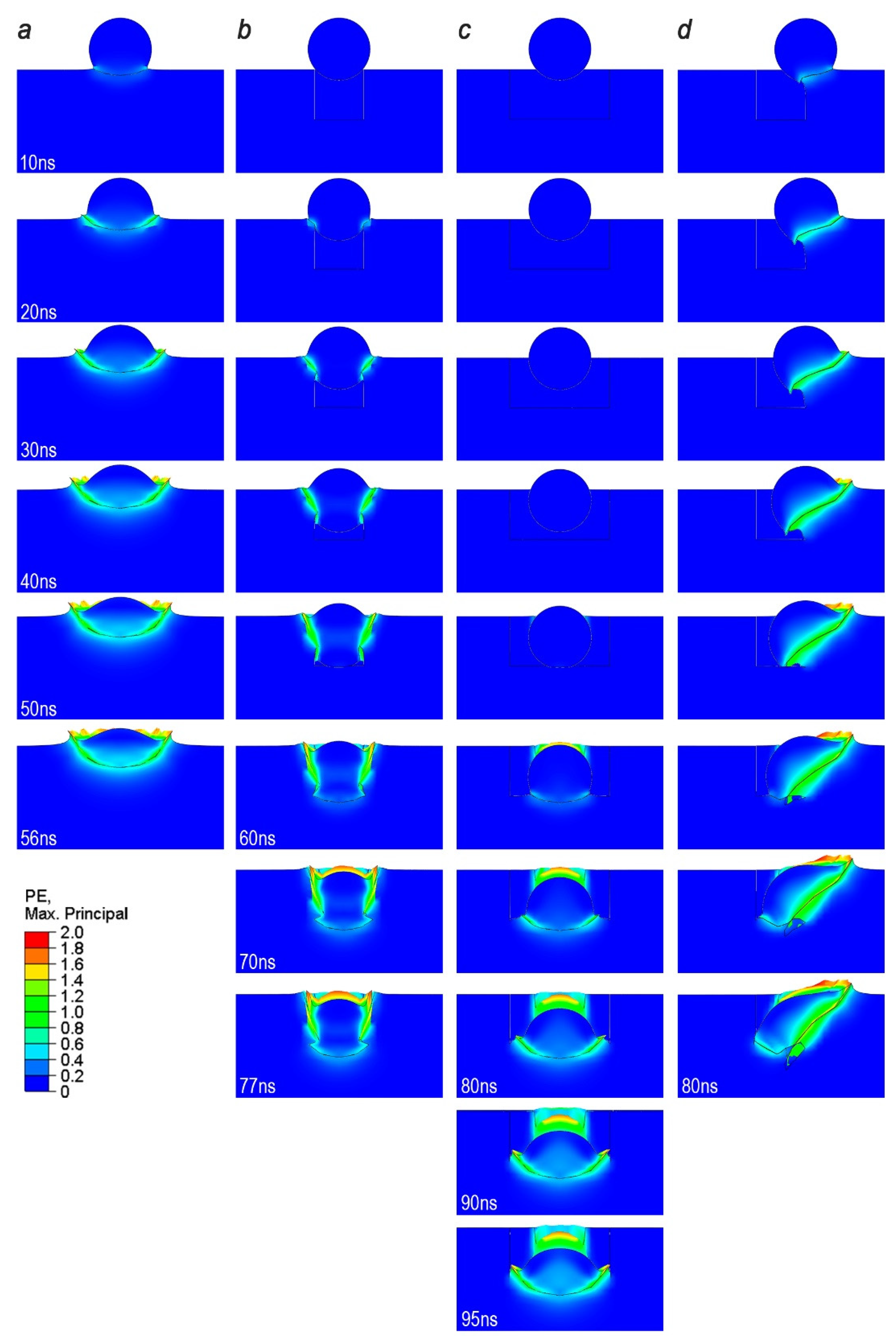
The simulated plastic strain (PE) evolution during collision is shown in
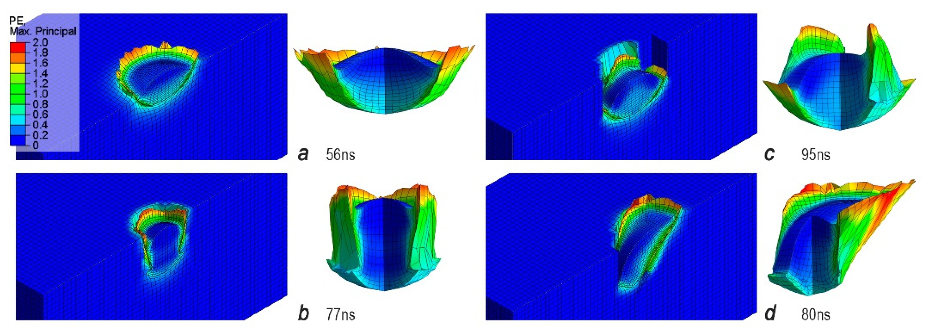
Figure 2 for four studied cases. PE at the end of the deformation process is demonstrated in
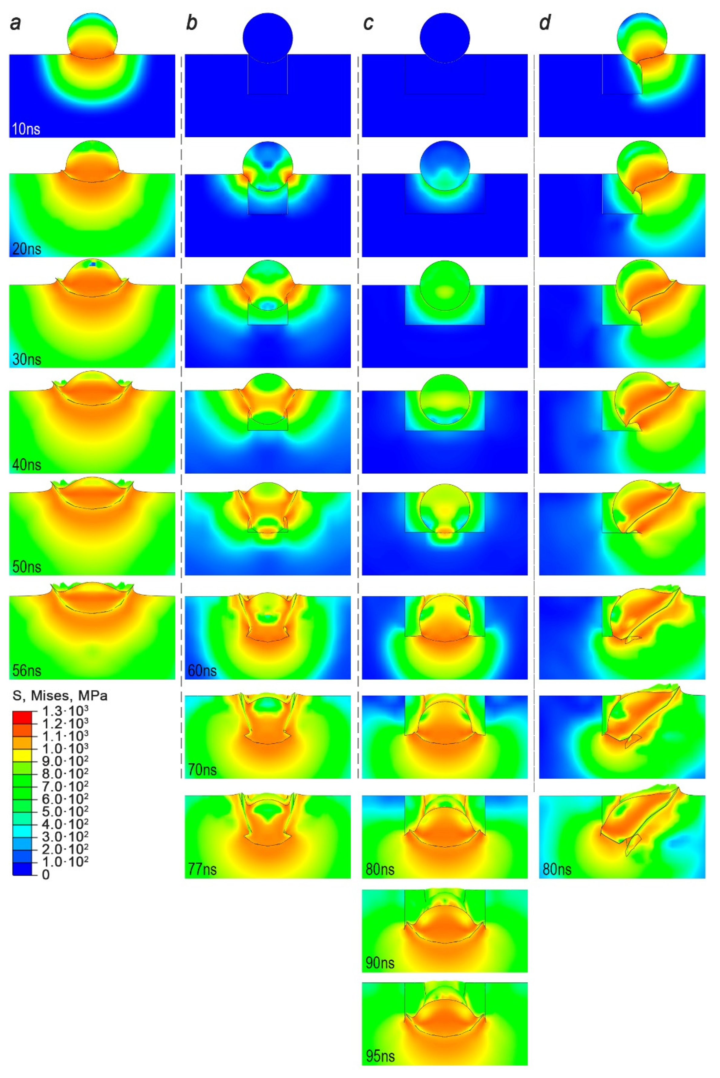
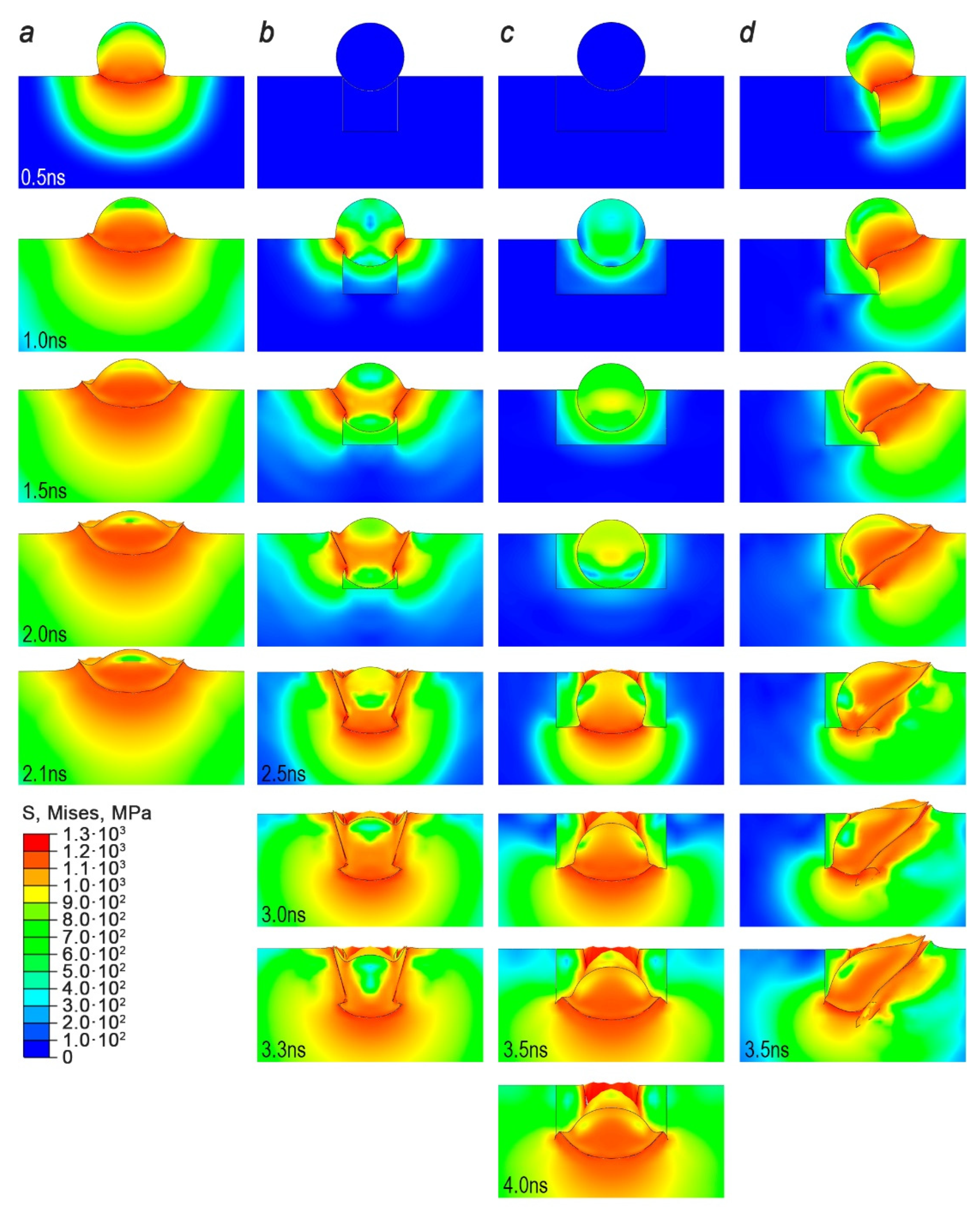
Figure 3. The von Mises stress distribution was also obtained and illustrated in
Figure 4 for different times of particle penetration into the substrate and at the end of penetration in
Figure 5. The temperature distribution during the penetration of the particle with the diameter of 50 µm into the substrate is shown in
Figure 6.
Figure 7 demonstrates the temperatures at the last moment of impact. All images show a cross section area through the vertical symmetry axis of the particle.
We assessed the contact plastic strain and stress as well as the temperature increase in the contact zones for all considered cases. In the cases (b) and (c), the first contact takes place at 30 ns, since the particle first has to enter the cavity. After 56 ns (case a), 77 ns (case b), 95 ns (case c) and 80 ns (case d), the impact of the considered contact partners is complete and the deformed particle remains in the substrate (
Figure 3).
For case (a), the plastic deformation (
Figure 2a) starts at the contact point of the particle surface with the flat surface or defect edges and is very fast during the penetration.
The strongest strain is localized at the material jet and in the plastic shear zone between the particle and the surface. The phenomenon of jetting is typical in the cold spray process and caused by the high shear stresses in the contact region [
3,
19,
20]. After the completed impact at 56 ns, the outer jet makes up a significant part of the particulate material forming a crown above the substrate surface (
Figure 3a).
In case b, the particle hits the edge of the cube-shaped microdefect and the first strain occurs at 20 ns. At the beginning, the plastic deformation is localized at a circular ring area of the particle and the substrate interface. Until 50 ns, the particle penetrates into the cavity. The middle part of the particle enters the void space of the cavity. Here, only the outer part of the particle deforms while the inner part remains the same. At 60 ns, the particle comes into contact with the bottom surface of the microdefect and deformation takes place in the lower part as well. At the end of the process, the highest PE is localized at the particle surface that was in contact with the edge of the cavity during the impact process. The inner and outer part of the particle show no signs of deformation. Interestingly, it can be seen that at the particle/substrate interface at the cavity hole and the bottom surface a material jet is formed. Compared to case (a), the jet is smaller. This can be attributed to the fact that the impact velocity in the bottom surface at 60 ns is smaller than the initial impact velocity of 800 m/s due to deceleration during penetration. The material jet at the cavity hole shows the same degree of PE compared to case (a). Both jets of the particle connect strongly with those of the substrate and lead to a strong connection through the resulting interlocking.
In case (c), the particle hits into a rectangular-shaped microdefect. Compared to case (b), the number of contact poins is two instead of four. For the investigated ideal case, where the particle starts at the middle of the microdefect, the edges of the elongated part do not come into contact with the particle. From the start to end of the penetration, no PE arises at the walls of the elongated part. The first occurence of PE is seen at 56 ns. Here, the particle surface deforms on the outer side of the cavity walls. From 56 to 95 ns, the particle penetrates into the bottom surface and PE can be seen here as well. At the end, the highest strain is localized at the microdefect walls and the bottom material jet.
In comparison to case (b), the material jet at the bottom part is more significant and the inside of the particle shows a low degree of deformation. It can be assumed here that the lower number of contact points shows a smaller degree in deceleration of the particle. Therefore, more kinetic energy remains that dissipates.
In case (d), the particle hits the edge of the cube-shaped microdefect. As expected, only the part of the particle which is in contact goes through severe deformation.
In this case, it is the right hand side. During the process of penetration at this place, deformation increases while the left side of the particle enters the void space of the cavity. At 56 ns, the particle hits the bottom surface of the cavity.
At the end, the highest plastic strain is achieved in case (d), since the volume of material that is deformed as a result of impact is the smallest. In this place, the material jet is located. The part of the particle that penetrates into the cavity shows only a small degree of deformation. A material jet is not seen here.
Figure 4 displays the von Mises stresses during the collision. The stresses first occur at the contact points, but spread very quickly to all directions. The von Mises stress distributions are different at the end of the simulation depending on the investigated cases (
Figure 5). While the absolute maximum values of the von Mises stresses for all considered cases are reached, the points of occurrence and the directions of propagation are distinguished. For the direction of propagation, it is crucial whether the particle hits four (case b) or two edges (case c) at the same time or whether it hits the microdefect centrally or not (case d). The increase of stress contributes to jetting. In case (a), the von Mises stress spreads homogenously from the point of contact uniformly through the surroundings of the surface (from 10 ns to 56 ns). The highest values of 1000 MPa are located near the penetration area within the particle and substrate. From
Figure 5a it can be seen that at the end the particle shows the highest von Mises stresses. Compared to the plastic strain, the von Mises stress spreads through the whole investigated substrate size. In case (b), the propagation of the von Mises stress is at the contact edges of the cube-shaped microdefect. When the particle hits the bottom surface at 50 ns, the von Mises stress reaches values near to the initial contact. In case (c), the occurrence of the von Mises stress is seen at 20 ns. Until 40 ns, the distribution is only near to the wall surface of the cavity and within the particle. From 56 to 95 ns, the von Mises stress spreads from the bottom part to upper and side parts of the substrate. In case (d), the distribution of the von Mises stress starts from the right hand side and evolves to the left with the increasing penetration depth of the particle. The highest values are more concentrated within the particle. Compared to the other cases, the stress at the surroundings of the substrate is lower. In
Figure 5d it can be seen that stress does not reach the outer edge of the substrate and is more located near the impact place.
Figure 6 shows the time evolution of the temperature for the different impact scenarios. In
Figure 7, the temperature increase at the end of the process can be seen. In the case for the impact on a flat surface (
Figure 6a), the temperature increase in the process from 10 to 56 ns starts at the boundary between particle and substrate. At the end, after 56 ns, the temperature increase is only located at the interface between particle and substrate. The highest temperatures are located at the material jet that were caused due to the adiabatic shear instability. Compared with
Figure 2, the temperature increase shows the same trend in distribution as the plastic strain. An increase in the whole substrate is not observed due to the adiabatic conditions chosen in the simulation. The trend of the temperature distribution for the cases where the particle is in an interaction with a microdefect is equal to the plastic strain distributions in
Figure 2. This can be attributed to the fact that heat generation depends on the amount of plastic work which dissipates during the impact process. A more detailed description is discussed below.
3.2. Case 2: Simulation of the Impact of 2.1 µm Particles
In the second case, the same contact scenarios (
Figure 1) for the smaller particles with a diameter of 2.1 µm and defects with reduced dimensions were simulated at the same specific impact energy. The overall deformation behavior showed in
Figure 8 is similar to the results for larger particles in
Figure 2. Due to the smaller particle size, the end of deformation process is reached much faster, and the corresponding collision times are 2.1 ns (case a), 3.3 ns (case b), 4.0 ns (case c) and 3.5 ns (case d).
During the particle collision on an ideal smooth and defectless surface (
Figure 8a), the particle flattens and the characteristic material jet is shown as well. However, the particle and substrate have smaller plastic strain values (PE up to 1.6) compared to the impact of a particle with a diameter of 50 µm (PE up to 1.8) (
Figure 2a). The smaller particle penetrates to a slightly shallow depth of about 3% with the formation of a crown of a lower height on the surface of the substrate by 5%, both values in relation to the particle diameter. The trend of the stress propagation during collision of smaller particle is similar. However, the von Mises stresses reach larger values (S up to 1300 MPa) (
Figure 9a) compared to the impact of a particle with a diameter of 50 µm (S up to 1200 MPa) (
Figure 4a). The propagation depth of the von Mises stresses, which exceed the value of 900 MPa, in the substrate is larger by 25% in relation to the particle diameter.
In the case of an impact on the substrate with a cube-shaped microdefect (
Figure 8b), the particle and the substrate also showed lower plastic strain values (PE up to 1.8) compared to the impact of a particle with a diameter of 50 µm, where PE reached 2.0 (
Figure 2b), but higher compared to the case of an impact on a flat surface. Maximum plastic strain for the case of an impact on the substrate with a rectangular-shaped microdefect has a value close to the cube-shaped microdefect. For both cases (
Figure 8b,c), the plastic strain is implemented in less material of the jet compared to corresponding cases of the particle with a diameter of 50 µm (
Figure 2b,c). Hovewer, from the distributions of stresses in
Figure 9b,c compared to similar cases for a particle diameter of 50 µm in
Figure 4b,c, it can be seen that for the smaller particles the higher plastic stresses were concentrated in the surface layer and jet (up to 1300 MPa) and larger area of the particle is subject to mechanical stresses smaller than 900 MPa.
The collision of the smaller particle on the edge of the cube-shaped microdefect leads to lower plastic strains (PE up to 1.8 in
Figure 8d) compared to the impact of the lagrer particle (PE up to 2.0 in
Figure 2d). The von Mises stresses have, as in all previous cases, higher values (up to 1300 MPa) (
Figure 9d) compared to the impact of a particle with a diameter of 50 µm (up to 1200 MPa) (
Figure 4d).
4. Discussion
The simulation results of particle penetration, stress-strain behavior and temperatures during impact were analyzed for both studied particle sizes.
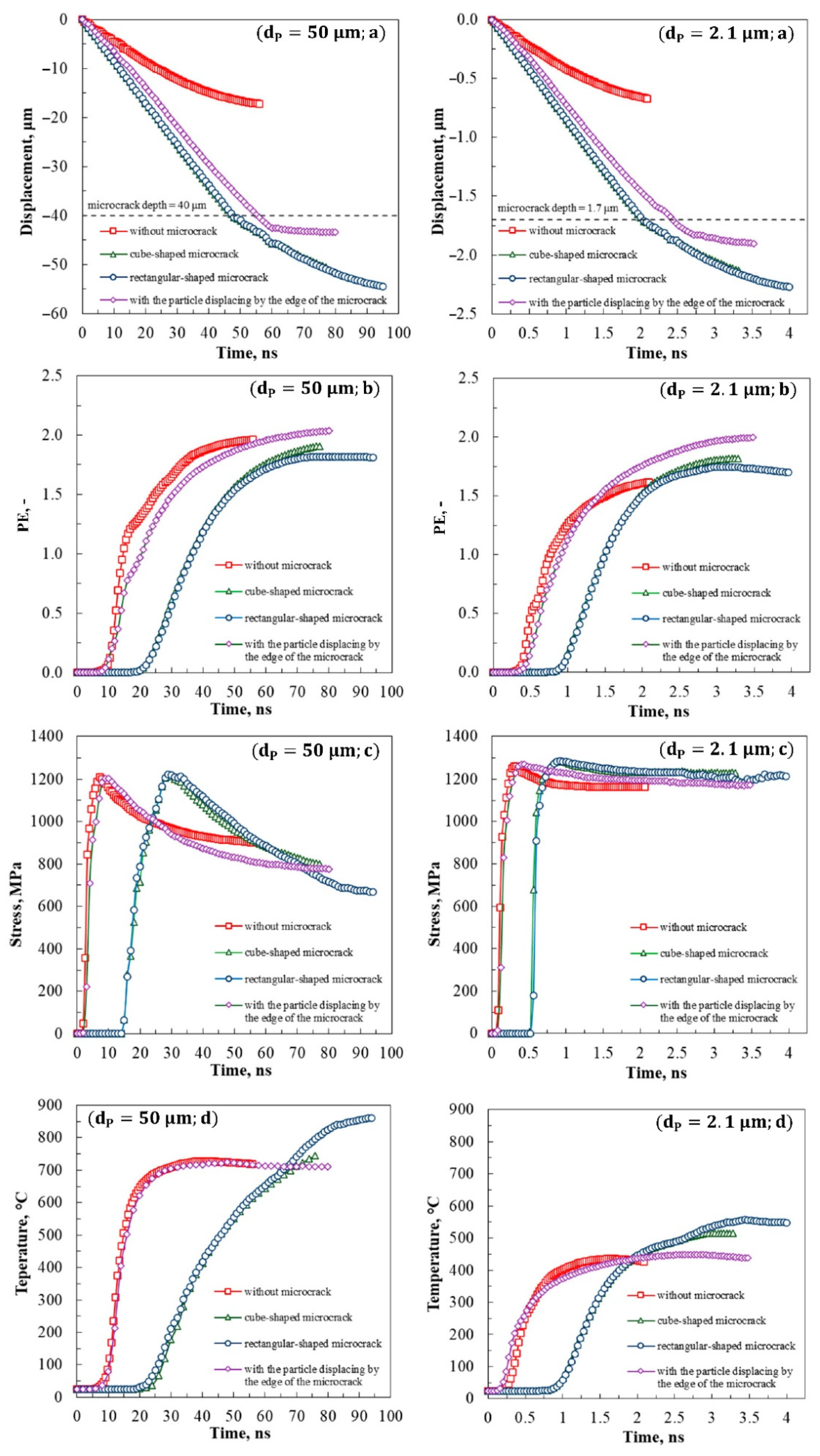
Figure 10 compares the evolution of the particle penetration depth into the substrate (a), the maximum values of plastic strain (b), the von Mises stresses (c) and the temperatures (d) during collision of a particle with the size of 50 µm (left diagrams) and 2.1 µm (right diagrams).
The particle penetration depth is defined as the position of the deepest point of the particle surface in the normal direction related to the initial substrate surface. In the case of the particle with a size of 50 µm (
Figure 10a left), the penetration into the substrate without a microdefect reaches the maximum depth of
17 μm. If we compare this case with the cases of axial central impact on a defect (
Figure 10b left), then the absolute value of penetration for cubic and rectangular-shaped defects is
51 μm and
54 μm, respectively.
With an eccentric impact on the edge of the defect, the nature of the change in the penetration depth similar to the central impact on the defect and in absolute value can be seen, the maximum penetration depth of the particle is 43 μm. Excluding the height of the defect (40 μm), the difference in penetration depth from the bottom surface of the defect () is 11 µm, 14 µm and 3 µm, respectively. The difference between these values and the depth of penetration into a flat surface referring to the initial particle diameter () is 12%, 6% and 28%, respectively.
For the particle size of 2.1 μm (
Figure 10a right), the penetration depth maximum values into the substrate and relative value are shown in
Table 2.
In the case of central impact on a microdefect (impact collision case b, c). for both particle sizes values of
are the same. For an eccentric impact,
has a smaller value for a smaller particle, which is associated to the lower value of the kinetic energy and the deformation nature in this case (
Figure 8d).
For the case of the particle collision on the edge of a cube-shaped microdefect, when the particle reaches the bottom surface of the defect, the rate of change of the penetration depth decreases, independent of particle size. That corresponds to approximately 60 ns for and 2.5 ns for .
The cases for the impact on the edge of the cube-shaped microdefect show the highest plastic strain PE ≈ 2.0 for both particle sizes (
Figure 10b), while in cases with a central impact (case b and c), a lower value of 1.75 is obtained. Here, the lower plastic strain is observed due to a smaller deformed volume (
Figure 2 and
Figure 8). Due to the late contact, the plastic strain evolution starts at 20 ns for a particle of 50 µm and 0.9 ns for a particle of 2.1 µm. In the case of a particle size of 2.1 μm (
Figure 10b right), the smallest plastic deformation was found upon impact on a defect-free surface. This can be explained by the fact that the effect of thermal softening is lower compared to impacts with larger particles. A constant plateau in all four cases indicates that thermal softening dominates over work hardening.
In
Figure 10c (left), the time evolution of the maximum von Mises stress for a 50 μm particle is plotted. In all four cases, the same trend can be seen, where the von Mises stresses increase steeply after contact and reach a maximum peak at 1200 MPa (
Figure 10c left). After that, the von Mises stress decreases until a constant value of 680 MPa for the rectangular defect case, at about 800 MPa for the cube-shaped defect with centerd particle and displacing by the edge and to 900 MPa for the substrate without defect. This is due to an initiation of elastic recovery.
For the cases with a particle size of 2.1 μm, the von Mises stresses increase steeply after contact and reach a maximum peak at about 1300 MPa (
Figure 10c right), but after that decrease slightly for all cases in a range of 1160 to 1200 MPa. This is due to the fact that the stress relaxation rate for both particle sizes is the same, but the considered time interval for a small particle is much less, i.e., for a time of 4 ns, the elastic deformation does not have time to be realized up to values similar to the case of a large particle impact.
The excessive shear stress during impact leads to a temperature rise between the surfaces of the particle and the substrate surface. The particle temperature in case 1 (particle size 50 µm) increases in a range of 710 to 860 °C (
Figure 10d left). The highest temperature of 860 °C is reached for the impact on a rectangular-shaped microdefect. In cases with a cubic defect and central and eccentric impact, most of the energy is spent on deformation, and not on friction. In the case of a rectangular-shaped microdefect, an increase in temperature can also occur due to the implementation of particle deformation along the side surfaces of the defect, resulting in the formation of a large contact spot, where there is friction of the deformed particle on these side surfaces. Therefore, higher temperatures can be expected. The case with a cube-shaped defect shows the same trend as the rectangular-shaped microdefect, but the maximum temperature of 720 °C is only slightly higher compared to the case without a microdefect. This can be attributed to a reduced heat loss for thermal conduction because of the smaller contact area.
Compared to the case with a defectless surface and 50 µm particle, the smaller particles showed lower maximum temperatures of around 400 °C due to the lower kinetic impact energy. The maximum temperatures for the cases with a cube-shaped, rectangular defect and with particle displacing by the edge of the defect are 500, 550 and 400 °C, respectively.
Upon impact with a substrate with a cube-shaped microdefect and a rectangular-shaped microdefect, the graphs of temperature change (
Figure 10d) and relative deformations (
Figure 10b) practically do not differ until the moment of time that corresponds to the particle reaching the bottom surface of the defect, which corresponds to 50 ns for
and 2 ns for
. For the case of a substrate with a cubic defect, the temperature has lower values and the plastic deformation has higher values. Additionally, for these cases, the rate of change in temperature and relative strain decreases (
Figure 10b,d), and the stresses in the substrate increase sharply (
Figure 4b,c and
Figure 9b,c).
For cases of impact without a microdefect, and with the particle collision on the edge of the cube-shaped microdefect, the decrease in the rate of temperature change (
Figure 10d) and the relative deformation of the particle (
Figure 10b) is also associated with a sharp increase in stresses in the substrate. This occurs as the surface area of the contact between the particle and the substrate increases, and when the contact surface changes from a nearly flat shape to a hemispherical shape. This is clearly seen in
Figure 4a,d after 10 ns and
Figure 9a,d after 0.5 ns, and after 60 ns for
and 2.5 ns for
. The particle collision on the edge of the cube-shaped microdefect is characterized by a further decrease in the rate of temperature change and relative deformation, that corresponds to the beginning of deformation of the bottom surface of the defect.
In the case of the cube-shaped microdefect for both particle sizes, the cavity volume is almost completely filled (
Figure 2b and
Figure 8b). On the top, there are elevations that are created by the jet. However, during the impact the filling does not take place homogeneously. The particle rubs on the sidewalls of the defect and a strong plastic deformation occurs here. The additional deformation at the cavity bottom leads to a plug that wedges onto the substrate on the sidewalls. Therefeore, it can be assumed that the bonding strength of the particle to the surface can result in an interlocking with a good quality of bonding.
The complete closure only occurs in the ideal case of a central impact. A small deviation from this, such as for the collision on the microdefect edge (
Figure 2d and
Figure 8d), or in the case of a larger volume of the microdefect in comparison with the particle, as for the rectangular-shaped microdefect (
Figure 2c and
Figure 8c), leads to a remaining small cavity from the bottom to the top of the microdefect.
5. Conclusions
In the performed numerical study, the influence of surface microdefects with a size that is comparable to the particle diameter on the collision by cold spray process was examined and compared to an impact on a smooth surface. The simulation was performed by the finite element method for single AISI 1045 steel particles impacted on an AISI 1045 steel substrate. Three idealized collision cases of a spherical particle on the surface with different cavities were studied in order to understand and analyze the phenomena in their basic features in comparison with the well-known case of particle impact on a smooth surface.
The size of the particle and microdefect were changed to investigate the effect on the overall result. For the smaller particle, the maximum temperature was lower but the overall deformation behavior remained the same because of the constant mass-specific impact energy for both studied cases. The comparison of the plastic strain, temperatures and stresses of the particle for different contact scenarios and defect geometries showed that the reached temperatures and stresses were roughly in the same size range but the deformation of the particle was completely different. It was shown that the particle impact on a defect leads to edgewise and locally inhomogeneous jet formation. During particle collision on the edges of a surface cavity, a primary jet is formed at the first contact zone, as it well known for the collision on a smooth surface. A secondary jet is created when the particle reaches and penetrates the bottom surface of the cavity. This was found for all studied defect geometries and sizes. These jets of material wedge themselves into the substrate in different directions and thus create a strong interlocking with the substrate. In a real process, this interlocking will create a high bond strength between the substrate and the coating and will avoid delamination. A volume filling behavior was observed in all studied cases, however, an eccentric impact on a microdefect will result in a higher void space within the cavity. Therefore, the impact location affects the deformation behavior.
In this work, the Johnson–Cook failure model was used for prediction of extremely high plastic deformation and stresses, which are a function of the strain rate at high-speed impact. The parameters used in this model were obtained from experimental studies in the literature and also take temperature dependence into account. Therefore, the effect of the temperature on the deformation can be described well. In future work, the simulation results can be validated with experimental tests to understand the influence of the deformation behavior during particle impact with defects on particle-substrate bonding.


