Article

Adhesion Strength of Amorphous Carbon Films Deposited on a Trench Sidewall

Department of Mechanical Engineering, The University of Tokyo, 7-3-1 Hongo, Bunkyo-ku, Tokyo 113-8656, Japan
*
Author to whom correspondence should be addressed.
Coatings 2022, 12(8), 1220; https://doi.org/10.3390/coatings12081220
Submission received: 24 July 2022 / Revised: 17 August 2022 / Accepted: 18 August 2022 / Published: 20 August 2022
(This article belongs to the Section Plasma Coatings, Surfaces & Interfaces)

Abstract

:
Hydrogenated amorphous carbon (a-C:H) films were deposited on the sidewall of 3-mm-wide stainless steel or Si trench, and the adhesion strength of the films was evaluated using a micro-scratch tester. Particularly, the effects of carbon ion implantation and Si-containing interlayer (a-SiCx:H) as the pretreatments on the adhesion strength of the a-C:H films prepared on the trench sidewall were investigated. It was found that both carbon ion implantation and interlayer improved the adhesion strength of the a-C:H films deposited on the trench sidewalls. In addition, the carbon ion implantation dominated the adhesion strength of the a-C:H films for the Si substrates, and the interlayer for the stainless steel substrates. In the case of the stainless steel substrates, the carbon was accumulated on the surface of the trench sidewall instead of implantation, whereas the carbon ions were implanted to the Si substrates on the trench sidewall to form a mixing layer. The a-SiCx:H interlayer forms Fe–Si bonds between the stainless steel substrate and the interlayer, which is thought to improve the adhesion strength. It was also found that there is a negative correlation between the trench depth and the adhesion strength regardless of the pretreatment methods.

1. Introduction

Since hydrogenated amorphous carbon (a-C:H) films have excellent mechanical properties, chemical stability, and smoothness [1,2,3,4,5], they have been applied to enhance the durability and releasability of various molds [6,7,8,9]. Among several deposition methods for a-C:H films, the plasma based ion implantation and deposition (PBII&D) has recently attracted much attention as a suitable deposition technique for three-dimensional targets [10].
In the bipolar-type PBII&D method as shown in Figure 1 [10,11,12], high-density plasma is generated around the target by applying a positive high voltage pulse directly to the target, and then a gradient potential layer called ion sheath is conformally formed around it by applying a negative high voltage pulse. The three-dimensional deposition is possible because the ions in the plasma are accelerated three-dimensionally from all directions of the target due to the potential difference in the ion sheath. However, as the scale of the three-dimensional target becomes smaller, the target is immersed in the ion sheath as shown in Figure 2, making it difficult to coat the film uniformly on all target surfaces [13,14]. In the deposition of a film with a trench-shaped target, which is a basic structure in molds, the smaller the scale D is, the more ions penetrate almost parallel to the trench sidewalls. In this study, the ion sheath thickness d is expected to be on the order of several centimeters [14], and the trench width is on the order of millimeters, suggesting that the film was deposited in the condition shown in Figure 2c. Although a certain amount of ion incidence to the sidewall occurs because the ions near the sidewall are attracted to the side direction by the electric field generated from the sidewall, the angle of incidence is very large, which causes problems in the quality of the films, such as mechanical properties and adhesion strength of the films [13,14]. In particular, it is essential to ensure sufficient adhesion strength for the practical use of a-C:H films deposited on three-dimensional targets such as molds.
In general, two pretreatment methods have been used to improve the adhesion strength of a-C:H films. One is carbon ion implantation into the substrate and the other is interlayer with high affinity with substrate and low internal stress. In the carbon ion implantation process, a negative high-voltage bias is applied to the substrate before a-C:H film deposition to form a mixing layer with a gradient of carbon ratios near the substrate surface, which improves the adhesion strength between the substrate and the film by increasing the number of bonds that directly bind the atoms of the carbon and the substrate [15]. It is also believed that the crystalline structure on the substrate surface is destroyed and becomes amorphous during the implantation of high-energy carbon ions. The destruction of the oxide layer on the substrate surface and the reduction of the internal stress in the film also contributes to the improvement of adhesion [15]. The adhesion strength of a-C:H film also can be improved by introducing a thin interlayer film, which has better adhesion strength than the a-C:H film to the substrate. In the case of a-C:H film deposition on steel substrates, Si-containing interlayers such as SiC and a-SiCx:H films have been widely used [16]. More Fe–Si bonds between the substrate and the interlayer, and more Si–C bonds between the interlayer and the a-C:H film improves the adhesion strength [17]. On the other hand, although the effectiveness of these two pretreatment methods has been confirmed for a two-dimensional flat substrate, there is no study that they were applied to three-dimensional targets such as trench sidewall, pipe inner surface and so on.
In this study, the effects of carbon ion implantation and Si-containing interlayer as the pretreatments for a-C:H film deposition on the adhesion strength of the a-C:H films were investigated. In order to investigate whether these two methods are also effective in coating structures with three-dimensional shapes such as molds, we studied trench structures, which are typical three-dimensional shapes, especially the sidewall where adhesion strength of coating is greatly reduced. The effects of combining both methods on the adhesion strength of the a-C:H films are also discussed.

2. Materials and Methods

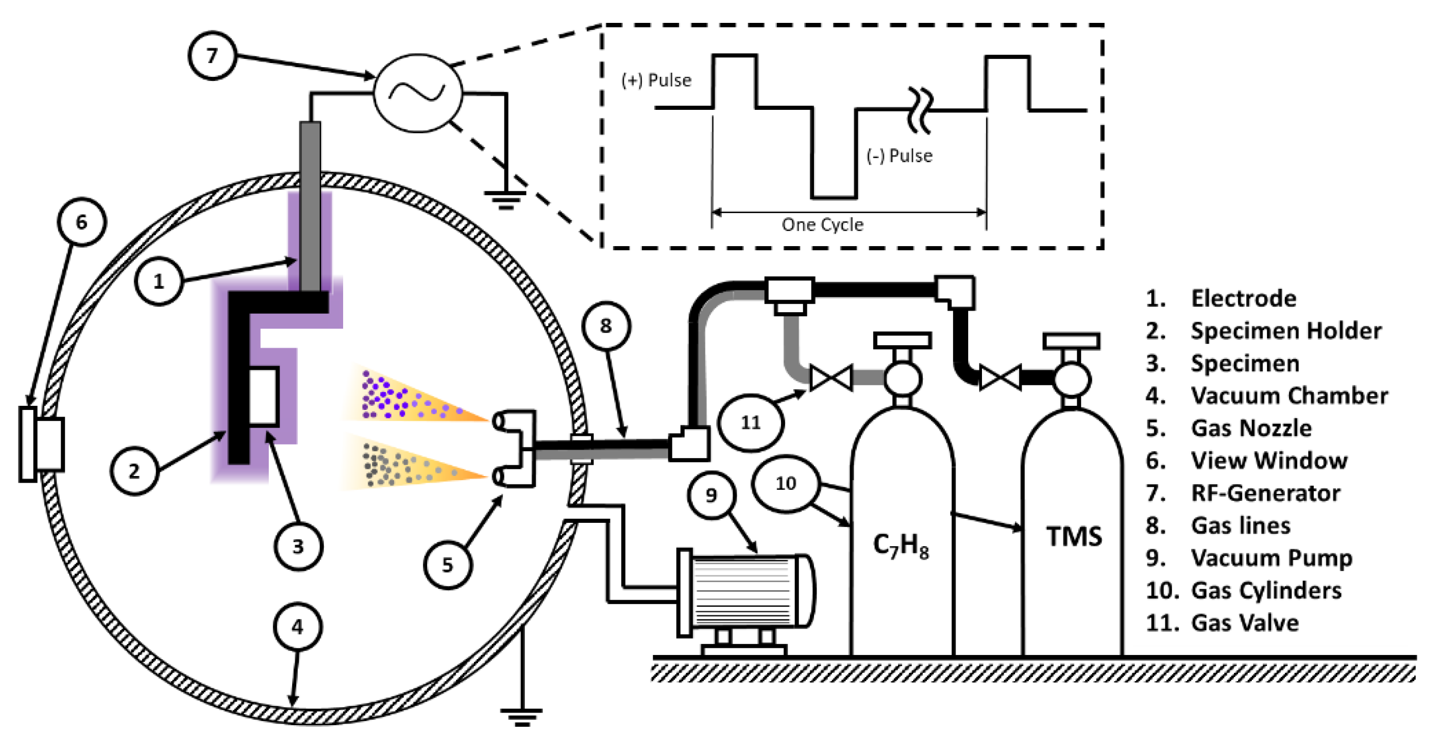
2.1. a-C:H Film Deposition System

An aluminum trench with a width (D) of 3 mm was fabricated, and silicon or stainless steel (JIS SUS430) plates with a chemical composition of Cr 16%, Mn 1%, Si 0.75%, P 0.04%, C 0.12%, S 0.03%, and Fe in balance was attached to both sidewall trench and flat surfaces as shown in Figure 3.
Two pretreatments and a-C:H film deposition, i.e., carbon ion implantation using CH4 gas, a-SiCx:H inter-layer deposition using Tetramethylsilane (Si(CH3)4, TMS) gas, and a-C:H film deposition using Toluene (C7H8) gas were conducted using a bipolar-type PBII&D system. Both Toluene and TMS are liquid at room temperature. Toluene is vaporized by heating at 40 °C and then fed into the chamber, whereas TMS is vaporized under low pressure without heating. All parameters of these three treatments are summarized in Table 1. A total of six different conditions with different combinations of treatments were applied to both Si and stainless steel substrates, to optimize the best film adhesion case as seen in Table 2. Condition A is a-C:H film with no pretreatment before the deposition. Conditions B, C, and D are the a-C:H films with carbon ion implantation, a-SiCx:H interlayer, and both pretreatments before film deposition, respectively. Conditions E and F are the substrates with carbon ion implantation and a-SiCx:H interlayer deposition, respectively, without a-C:H film deposition.

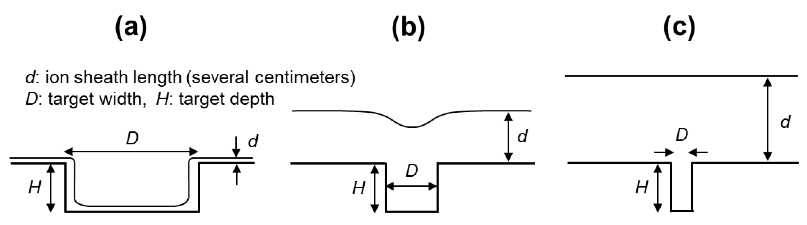
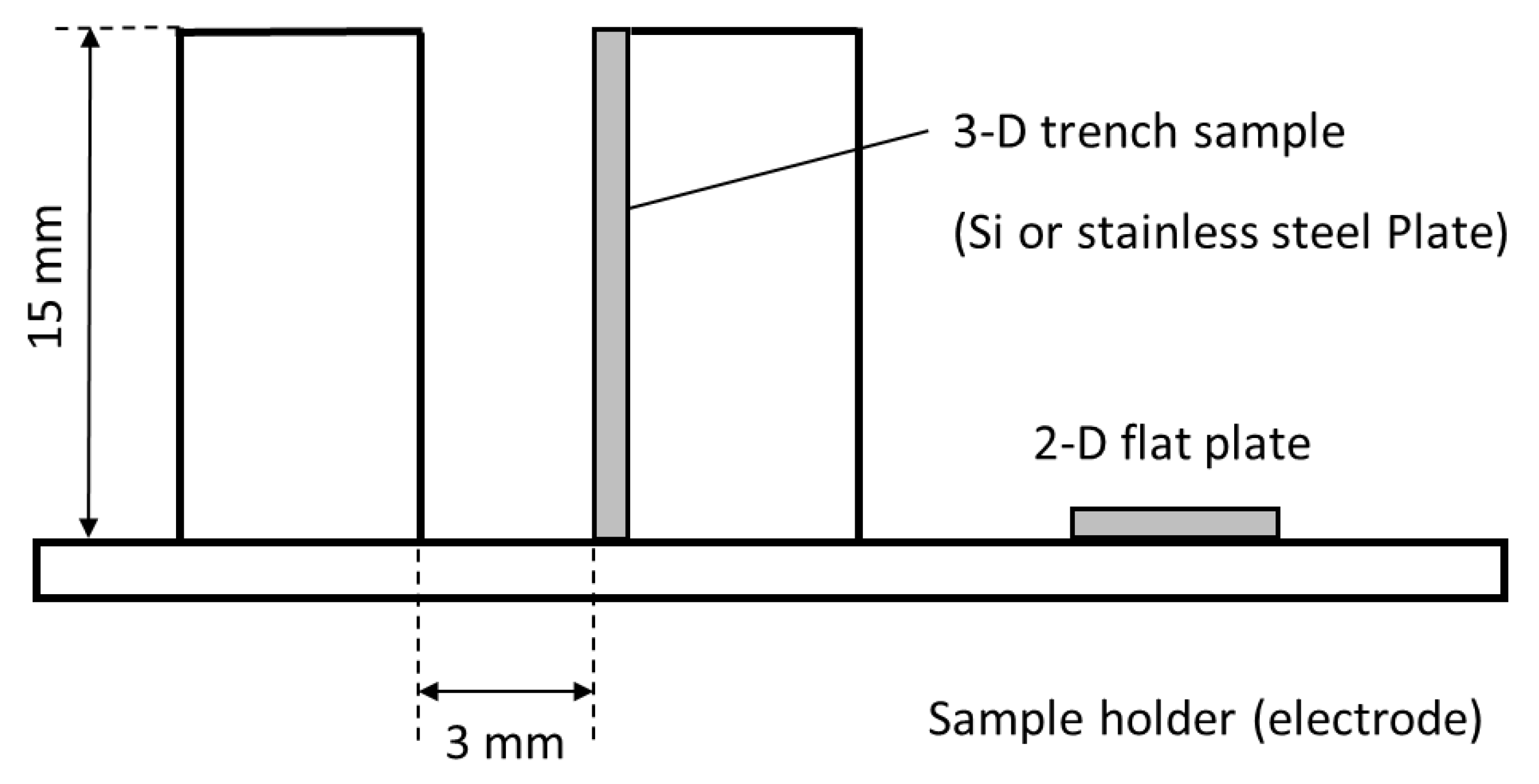
2.2. Simulation Methodology

SRIM-stopping and range of ions in matter software [18,19] was used to analyze the implantation behavior of carbon ions into the substrate to predict the depth of implantation. The calculation conditions (Table 3) were determined considering the actual experimental conditions. The angle of incidence in this calculation is the angle between the ion incident on the surface and the line normal to the surface at the point of incidence. The incident angle was set to 0° for the planar sample and 80° for the plate placed on the trench sidewall, referring to the plasma simulation results of our previous study [13].

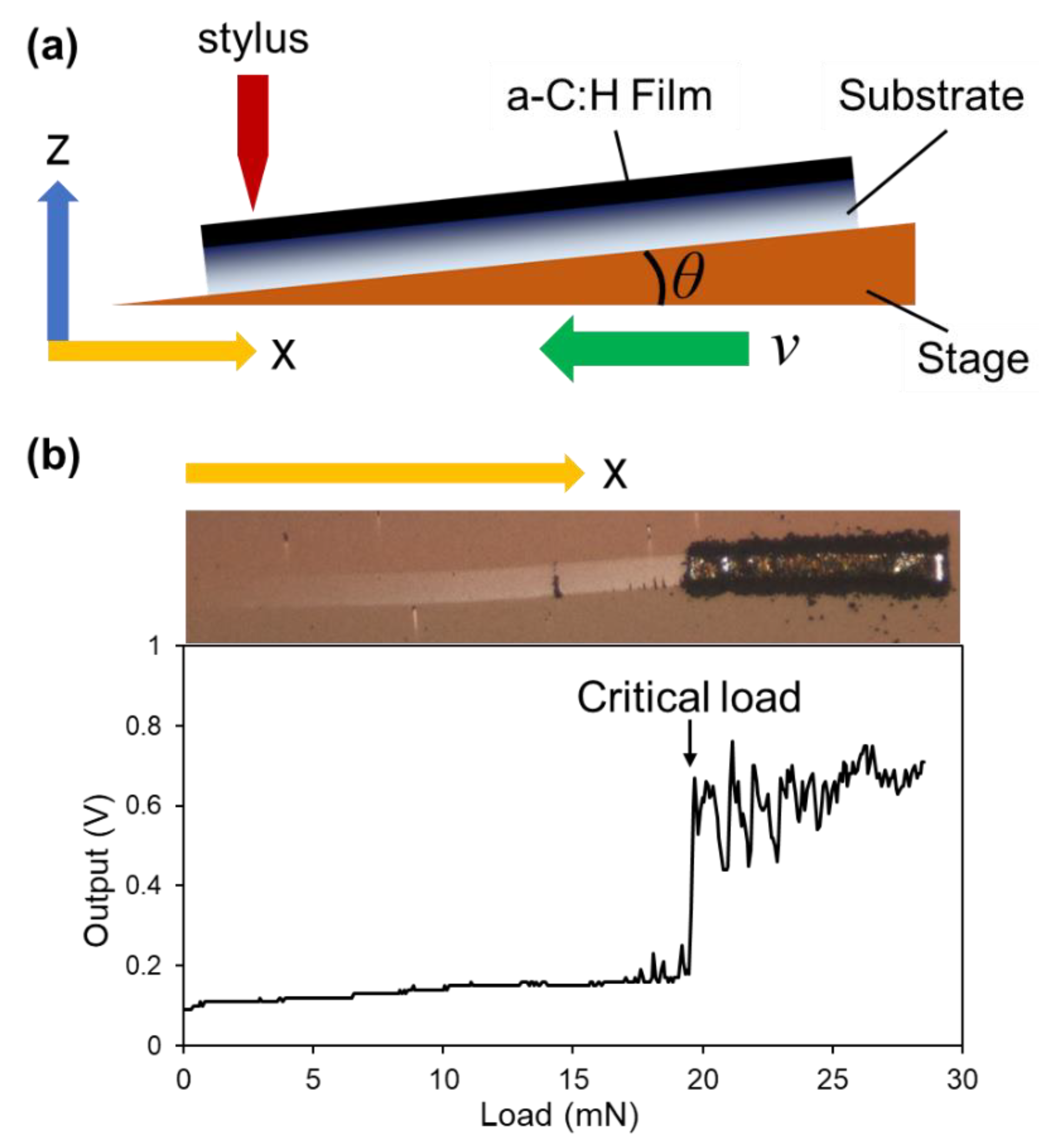
2.3. Measurement and Analysis

The adhesion strength of the a-C:H films to the substrates was evaluated using the micro-scratch tester [20,21]. In the micro-scratch test, the diamond indenter is in contact with the surface of the film while the indenter is vibrating in the y-direction with an amplitude of 80 µm (Figure 4a). The stage is tilted at an arbitrary angle θ and the vertical load applied to the sample from the indenter is gradually increased as the stage moves in the horizontal direction as shown in Figure 4a. Since the stage moves at a constant speed (v), the magnitude of the load (W) applied to the sample can be calculated from the stage angle (θ), the time elapsed since the start of the scratch (t), and the spring constant of the diamond-tipped stylus (k) from the following Equation (1).
W = kvt tan θ
A typical example of the electrical output waveform obtained in this experiment is shown in Figure 4b. Since the electrical output increases rapidly when film delamination occurs, the load at that time is recorded as a critical load of delamination, and the adhesion strength of the film can be quantitatively evaluated by comparing the load at that time. In other words, the greater the critical load of delamination, the greater the adherence of the film. In this experiment, the stylus diameter and spring constant of the indenter were 5 µm and 210.4 g/mm, respectively, and the stage angle θ was set to 0.5°.
The film thickness of each sample was measured with a surface profilometer to test the film thickness effects on a-C:H film adhesion to the substrate. To evaluate the implantation behavior of carbon ions into the substrate, the depth analysis of the samples with carbon ion implantation was performed using X-ray photoelectron spectroscopy (XPS) PHI5000 VersaProbe equipment by ULVAC-PHI, Inc., Kanagawa, Japan. The cross-section of the stainless steel plates was cut and polished to a mirror-like surface with Silicon-Carbide (SiC) sandpaper from #280 to #4000 and alumina powder solution with Al2O3 particles sizes of 3, 0.3, and 0.05 µm. The microstructure morphologies of both the surface and the cross-section were investigated using JSM-7500FA scanning electron microscope (SEM) by JEOL Ltd., Akishima, Japan. Renishaw Raman spectroscopy was employed using argon ion laser with a wavelength of 514 nm.

3. Results and Discussions

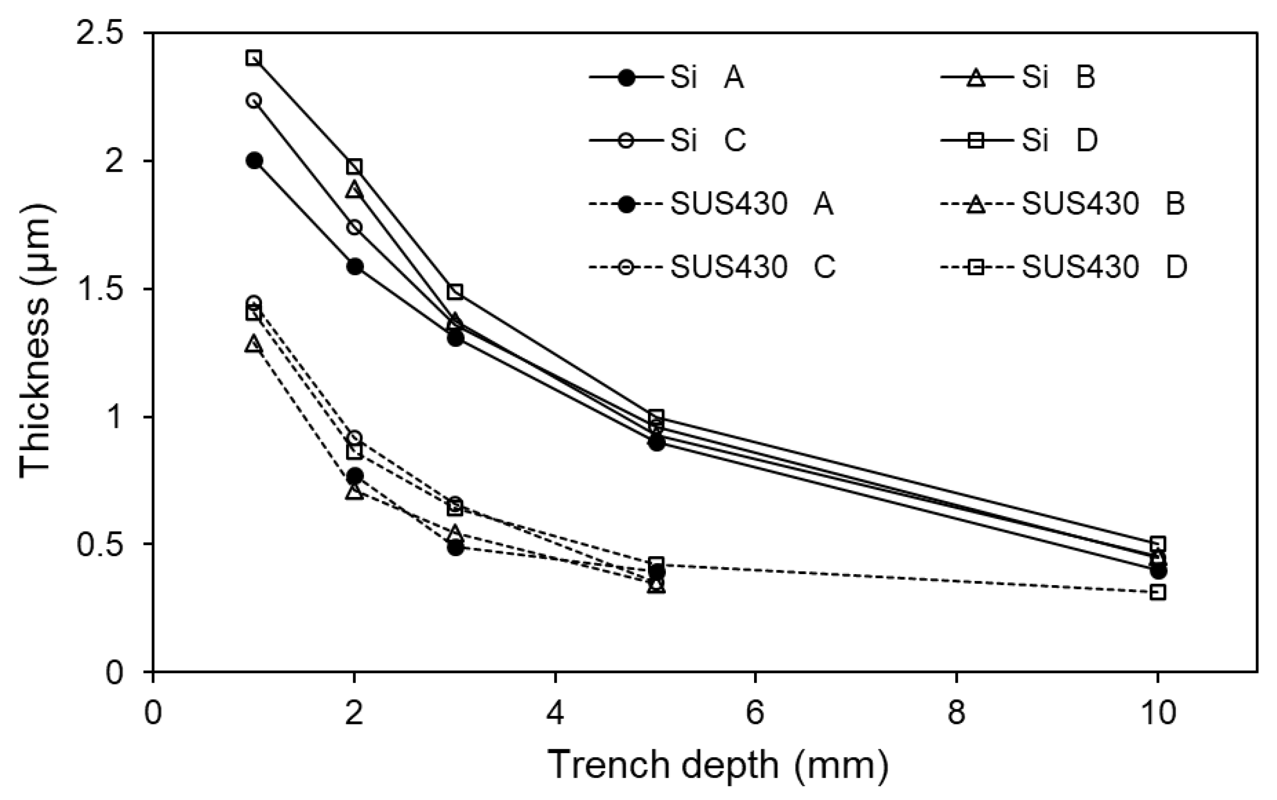
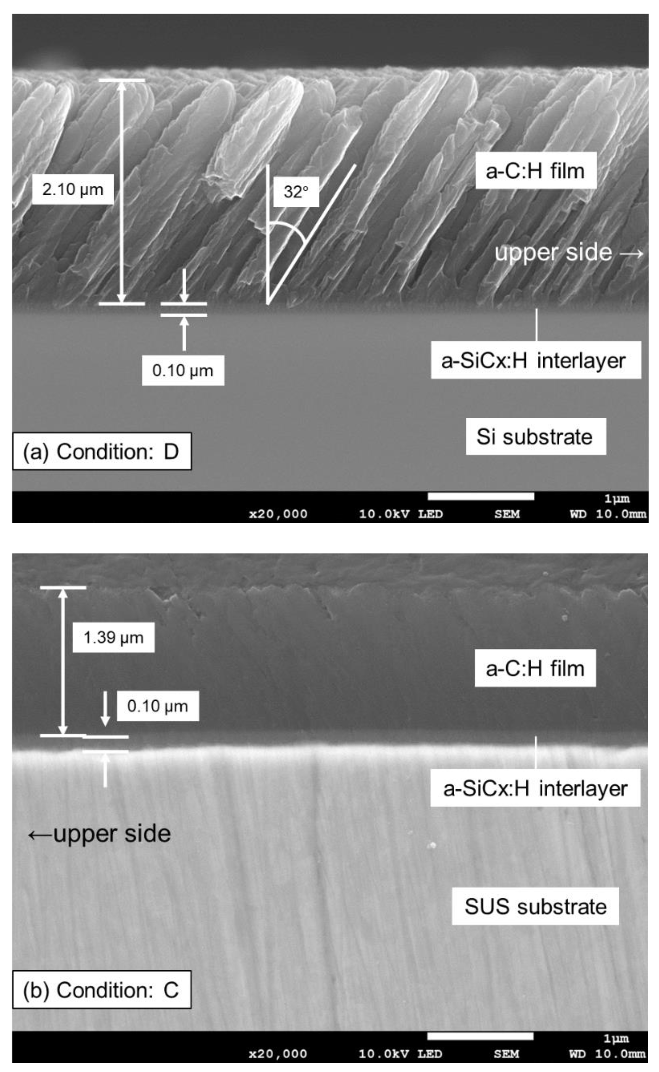
3.1. Deposition of a-C:H Films

Figure 5 shows the thickness of a-C:H films prepared by the deposition conditions A to D listed in Table 2. There is a negative correlation between film thickness and sidewall trench depth in all samples starting from the film thickness of 2–2.4 µm for the Si plate and 1.3–1.5 µm for the stainless steel plate at 1 mm depth from the trench top surface. The a-C:H film thickness tends to decrease to the value of 0.4–0.5 µm at 10 mm trench depth for all plates. In our previous study [13,14,22], plasma simulations showed that the incident fluxes of ions and radicals decrease as the Si trench depth increases. The behavior of the total flux of ions and radicals in the trench-depth direction was in good agreement with the behavior of the a-C:H film thickness mentioned above. It is found that the growth of a-C:H film thickness on the stainless steel plates is about half that on the Si plates at all trench depths. Since C atoms have a higher affinity for Si atoms than for Fe [23], the sticking coefficient of C ions and radicals to the substrate surface in the plasma during film deposition is higher for Si substrates. This is thought to be the cause of the difference in deposition rate.
Figure 6 shows a cross-sectional SEM image of conditions C and D at a trench depth of 2 mm of both Si and SUS430 samples. The Si substrate sample with condition D (duplex interlayer treatments) is shown in Figure 6a. a-SiCx:H interlayer with the thickness of 0.1 ± 0.05 µm is observed between 2.1 ± 0.2 µm thickness of a-C:H film Si substrate. In addition, inclined growth toward the upper side of the trench is detected in the a-C:H film, indicating that the ions are incident with an angle of 32° to the trench sides. The SUS430 substrate sample with condition C (with interlayer only) is shown in Figure 6b. The a-SiCx:H interlayer of 0.1 ± 0.06 µm and a-C:H film of 1.39 ± 0.37 µm at almost the same inclined angle were distinctly observed. There is a minimum existence of oxide contamination layer between these distinct deposited layers which will be later confirmed by the following analysis which clearly indicated good compatibility of these layers. It is also worth noting that distinct morphologies of a-C:H film can be clearly detected in both Si and SUS430 samples which indicate different properties and growth mechanisms of this amorphous layer deposited on top of different substrates.
Figure 7 shows the Raman spectra measured at trench depths of 2 mm for the samples deposited on both Si and SUS430 substrates under condition A (a-C:H deposition with Toluene only). The G and D peaks are detected for both substrates, and the slope of the two spectra is higher than the typical 2-D flat plates due to both the photoluminescence effect and hydrogen component [24,25]. This is thought to be because a larger proportion of radicals, which have lower energy than ions, are incident on the trench sidewall surface during film deposition, resulting in a lower film density and more defects compared to the a-C:H films deposited on a 2-dimensional flat surface.

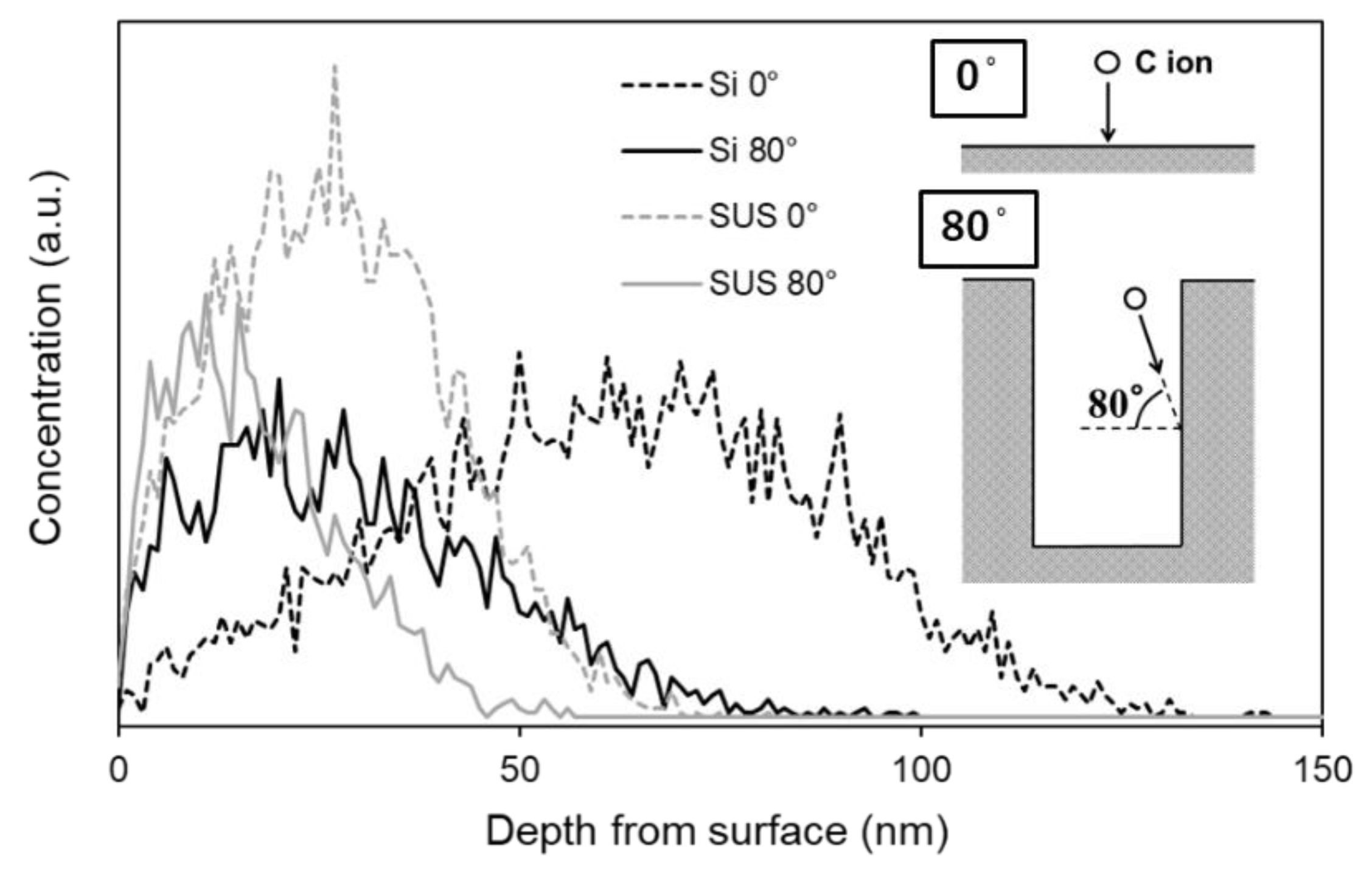
3.2. Simulation of Carbon Ion Implantation by SRIM

Figure 8 shows the distribution of the implantation depth of carbon ions obtained by SRIM simulation. As shown in the figure, the implantation depth of carbon ions into the stainless steel layer is smaller than that into the Si layer, suggesting that stainless steel substrates are more difficult to implant carbon ions than Si substrates. It is found that the implantation depth of carbon ions into the trench sidewall is much smaller than that into the flat plate. In the case of a flat surface, the depth of implantation reached 130 nm for Si substrate and about 70 nm for stainless steel substrate. On the other hand, the depth of implantation reached 80 nm for Si substrate and about 50 nm for stainless steel substrate in the case of the trench sidewall.

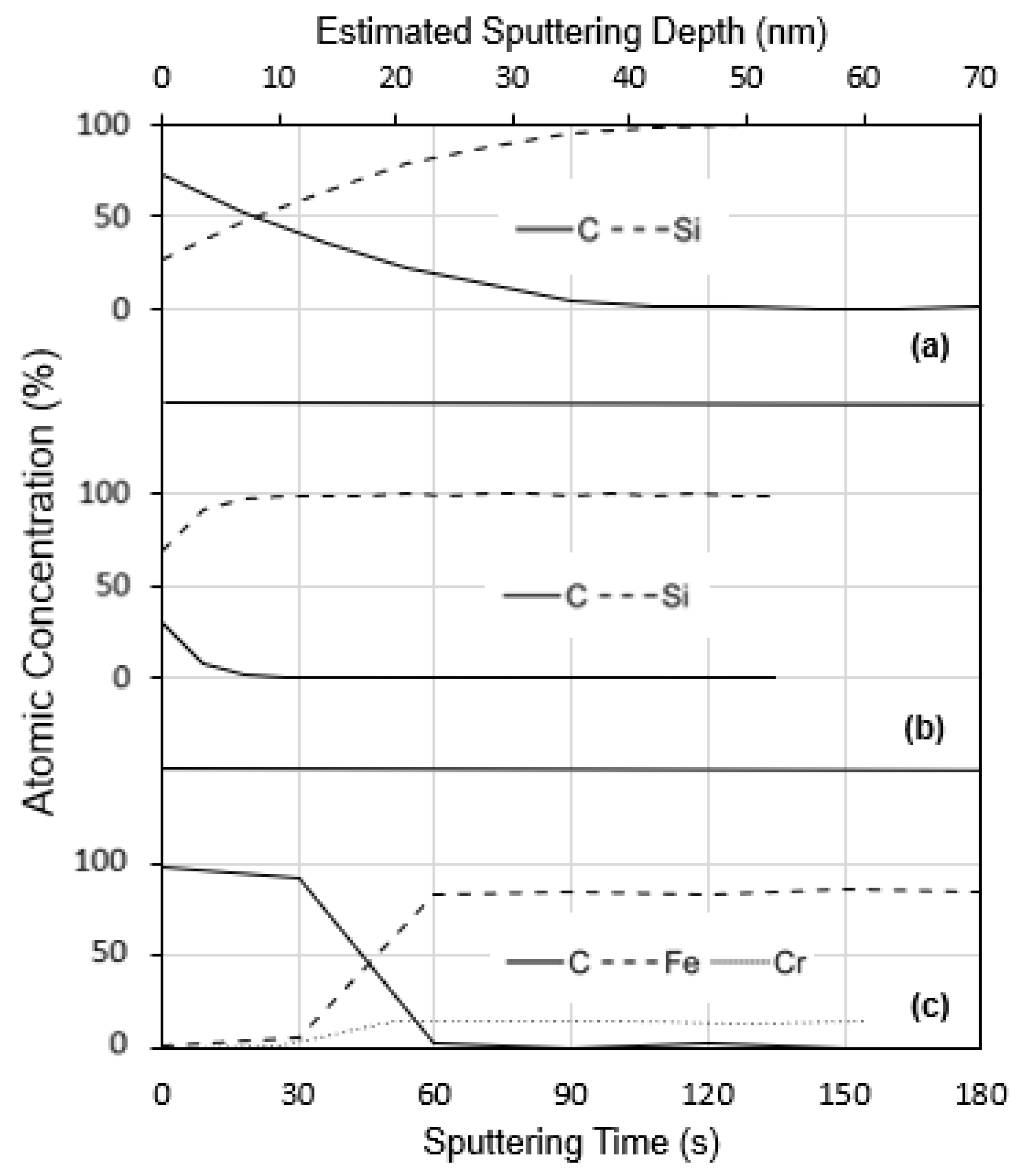
3.3. Evaluation of Carbon Ion Implantation by XPS

Figure 9 shows the depth profiles of the elemental composition for sample E (carbon ion implantation only) obtained by XPS measurements. Oxygen was also identified in the raw data, but it was removed as it was due to contamination and not necessary for the discussion of this study. The sputtering time of Ar+ ions on the horizontal axis corresponds to the depth from the surface, and the sputtering rate is about 0.33 nm/s based on SiO2. The carbon ions were implanted to the depth of about 40 nm (120 s) for the 2-dimensional Si flat plate (Figure 9a), and in the case of trench sidewall (at a position of 2-mm-depth), carbon ions were implanted to a depth of less than 10 nm (30 s) as seen in Figure 9b. It was found that a layer where the ratio of carbon changes gradient by implantation is created near the surface for the Si sample on the trench sidewall as well as the flat Si sample, though the implantation depth in the case of the sidewall is smaller than in the case of the flat sample. Although the implantation depths of both flat plate and trench sidewall were smaller than those of the simulation results shown in Figure 8, the trend that the implantation depths were smaller on the trench sidewall than on the flat surface was consistent, suggesting that the implantation depths on the trench sidewall were smaller due to the oblique incidence of carbon ions on the substrate. This is confirmed by the SEM image in Figure 6a. On the other hand, in the case of the stainless steel substrate placed on the trench sidewall, a layer with a carbon ratio of nearly 100% is formed near the surface (Figure 9c), suggesting that most of the carbon ions were accumulated on the surface as an amorphous carbon film instead of forming a carbon gradient layer due to a low incident ion energy. However, below the surface, the carbon concentration starts to sharply decrease from the depth of 10 nm (30 s) and completely fades at the depth of 20 nm (60 s). At the same time, both Fe and Cr concentrations raise to their original values of 80 at.% and 16 at.%, respectively. This indicates that there is a small 10 nm intermediate layer of iron-carbides (Fe–C) and chromium-carbides (Cr–C) separating the surface amorphous carbon film and the original stainless steel substrate. This layer is formed due to the relatively high energy of incident carbon ions before it reaches the saturation limits, and then the carbon ions accumulate on the surface.

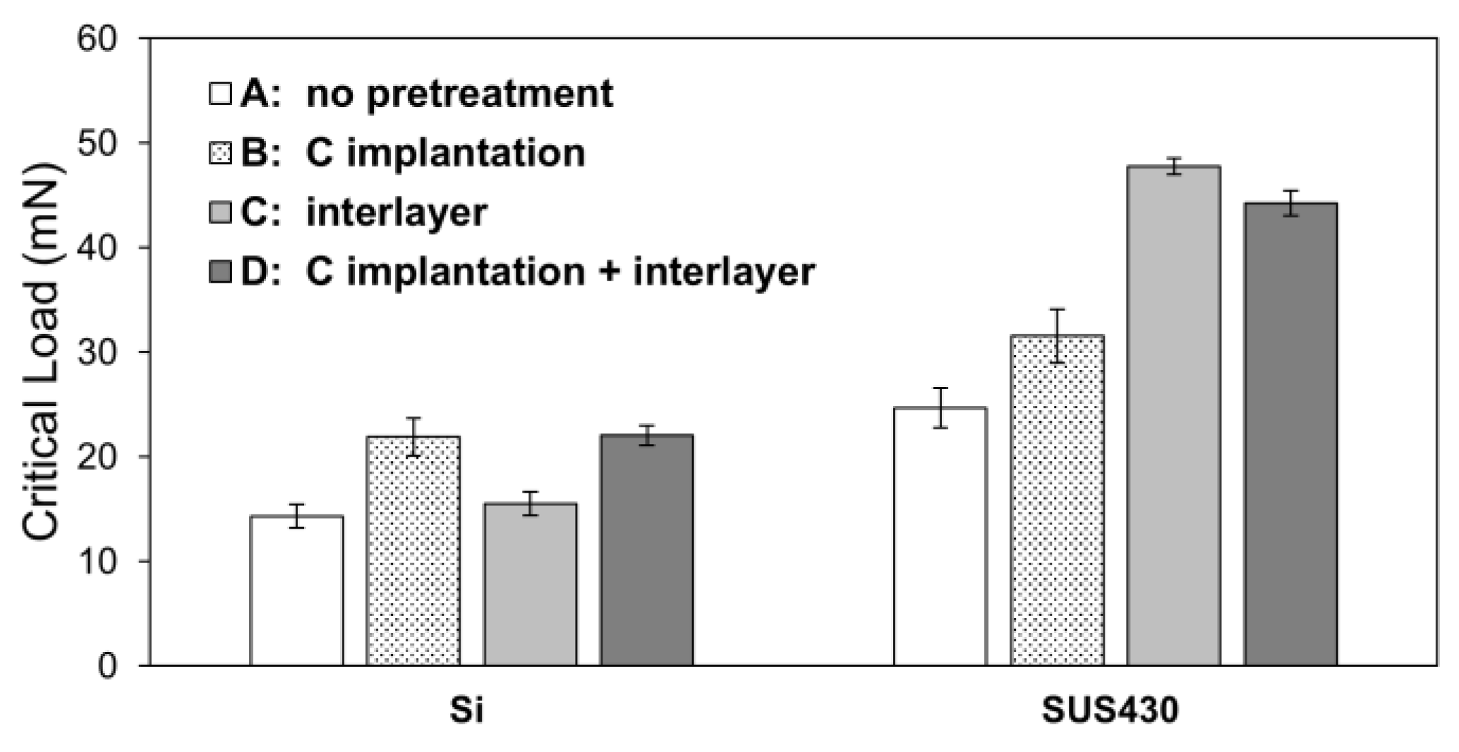
3.4. Adhesion Strength of the a-C:H Films

The critical loads of delamination for each a-C:H film were measured at a trench depth of 2 mm by the micro-scratch tester, and the results are shown in Figure 10. The adhesion strength of the stainless steel substrate was higher than that of the Si substrate. A previous study [18] reported a negative correlation between film thickness and adhesion strength for amorphous carbon film above a thickness of 110 nm in the deposition of two-dimensional flat plates, which is thought to be due to the increase in compressive stress in the film as the film thickness increases. As shown in Figure 5, the film thickness of the Si substrates is greater than that of the stainless steel substrates, and this may be the reason why the adhesion of the stainless steel substrates is higher than that of the Si substrates.
Focusing on the effect of the individual pretreatment method on the adhesion strength, the critical load of condition A (without any pretreatment) is the lowest for all other samples, indicating that adhesion strength can be improved by pretreatment. In the case of the Si substrate, condition B (with implantation only) and D (with both implantation and interlayer) showed the highest adhesion strength than other samples, that is, carbon ion implantation was most effective in improving the adhesion strength of a-C:H film on the Si substrates. On the contrary, stainless steel substrate sample of condition C (interlayer only) shows the highest adhesion strength than other conditions, and it can be said that the adhesion strength is dominated by the interlayer. For both substrates, the critical loads were not further improved though the two pretreatments of the ion implantation and the interlayer were combined.

4. Discussion

4.1. The Effect of Carbon Ion Implantation

As shown in Figure 10, the carbon ion implantation improved the adhesion strength of a-C:H films on both Si and stainless steel substrates placed on the trench sidewalls, and the effect was more pronounced on Si substrates. The results of the XPS depth analysis of the substrates after carbon ion implantation showed that a carbon film was accumulated on the stainless steel substrate instead of implantation, while a layer with a gradient of carbon content was formed near the surface in the Si substrate. In a two-dimensional flat plate, the adhesion strength of a-C:H films can be improved by the formation of more chemical bonds between the implanted carbon atoms and the atoms in the substrate in the mixing layer [15]. The improved adhesion strength of the Si substrates placed on the trench sidewall is also attributed to the same mechanism mentioned above. On the other hand, the carbon ion implantation process slightly improved the adhesion strength of a-C:H films deposited on the stainless steel substrate. The reason for this is the formation of a thin carbon mixing layer on the stainless steel substrate due to a much shallower depth of carbon ion implantation than that on the Si substrates. As mentioned above, most of the incident carbon ions on the stainless steel surface placed on the trench sidewall are accumulated on the surface to form a thin carbon layer and are not implanted due to low incident energy.

4.2. The Effect of the Interlayer

As shown in Figure 10, the a-SiCx:H interlayer remarkably improved the adhesion strength of a-C:H films on the stainless steel substrates, whereas the effect of the interlayer on the adhesion strength was negligibly small for the Si substrates. It is generally believed that a-C:H films do not adhere well to steel substrates because the affinity between Fe and C atoms is relatively low and sufficient Fe–C bonds are not formed at the interface between the a-C:H film and the steel substrates [23]. In a previous study of two-dimensional flat plates, it was found that the introduction of an a-SiCx:H interlayer enhanced the adhesion of the a-C:H film to the steel substrate, because the Si atoms in the interlayer have a high affinity for both Fe and C, and sufficient chemical bonds are formed at the respective interfaces [17,23]. The same phenomenon is considered to have occurred on the trench side. The reason why the effect of the interlayer was limited on the Si substrates is considered to be that sufficiently strong chemical bonds were formed between Si substrate and a-C:H film without the interlayer.
Comparing the effects of carbon ion implantation and the interlayer, it was found that carbon ion implantation was more effective in improving the adhesion strength of a-C:H films on the Si substrates, while the interlayer was more effective in improving the adhesion strength of a-C:H films on the stainless steel substrates. In the case of Si substrate, the elemental composition between the substrate and the film changes continuously when carbon ion implantation is performed, and it changes in a stepwise manner when the interlayer is prepared. Carbon ion implantation, which results in a continuous compositional distribution, is considered to form more Si–C bonds. Besides, carbon ion implantation has an effect not only on compositional distribution but also on strengthening interfacial bonds by breaking the crystal structure of the substrate surface and making it amorphous [15]. These suggest that carbon ion implantation was more effective in improving adhesion on Si substrates. In the case of stainless steel substrates, the effect of carbon ion implantation is small due to insufficient energy of the ions during the implantation and the formation of a carbon layer due to the deposition on the surface. Besides, more stable chemical bonds are formed in the interlayer, unlike carbon ion implantation. These are the possible reasons why the effect of the interlayer is greater than that of carbon ion implantation.
Though both carbon ion implantation and the interlayer as the pretreatments were carried out, the adhesion strength was not further improved. In the case of the trench sidewall, the effect of combining the two pretreatments was limited, that is, the influence of one of the two pretreatments on adhesion strength for the Si and stainless steel substrates is dominant.

5. Conclusions

In this study, a-C:H films were deposited on the Si and stainless steel substrates placed on the trench sidewall with a width of 3 mm, and the effects of two pretreatments before the a-C:H film deposition, i.e., the carbon ion implantation and the interlayer, on the adhesion strength of the films was investigated. The obtained results are as follows.
  • The adhesion strength of the a-C:H films deposited on the stainless steel substrates was higher than that on the Si substrates. The reason for this is thought to be that the compressive stress in the films deposited on the stainless steel substrates is smaller because the film thickness of the stainless steel substrates is smaller due to the difference in deposition rate.
  • As the pretreatments, carbon ion implantation and preparation of a-SiCx:H interlayer were effective in improving the adhesion of a-C:H films on the trench sidewalls.
  • For the Si substrates, the carbon ion implantation was more effective in improving the adhesion strength of the a-C:H films than the a-SiCx:H interlayer. The carbon gradient layer on the near-surface of the Si substrate by the carbon ion implantation was successfully formed.
  • For the stainless steel substrates, the a-SiCx:H interlayer was more effective in improving the adhesion strength of the a-C:H films than the carbon ion implantation. From the SRIM calculations, it is considered that the implantation effect on stainless steel substrates was smaller than that on Si substrates because of the difficulty in implanting carbon ions onto stainless steel substrates, resulting in the deposition of a carbon film on the surface of the stainless steel substrates.
  • In the trench sidewall, there was no synergistic effect to improve the adhesion strength by combining the carbon ion implantation and the a-SiCx:H interlayer on both the Si and stainless steel substrates, indicating that the more effective pretreatment on each substrate dominates the adhesion strength of a-C:H films.

Author Contributions

Conceptualization, K.T. and J.C.; methodology K.T. and A.F.; software, K.T.; validation, K.T., A.F. and J.C.; formal analysis, K.T.; investigation, A.F.; resources, K.T.; writing—original draft preparation, K.T.; writing—review and editing, A.F. and J.C.; supervision, J.C. All authors have read and agreed to the published version of the manuscript.

Funding

This research was funded by Die and Mold Technology Promotion Foundation for research and development of molds, 2018.

Institutional Review Board Statement

Not applicable.

Informed Consent Statement

Not applicable.

Data Availability Statement

Not applicable.

Acknowledgments

This research was supported by a grant from the Die and Mold Technology Promotion Foundation for research and development of molds.

Conflicts of Interest

The authors declare no conflict of interest.

References

  1. Robertson, J. Diamond-like amorphous carbon. Mater. Sci. Eng. R Rep. 2002, 37, 129–281. [Google Scholar] [CrossRef] [Green Version]
  2. Liu, X.; Yang, J.; Hao, J.; Zheng, J.; Gong, Q.; Liu, W. Microstructure, mechanical and tribological properties of Si and Al co-doped hydrogenated amorphous carbon films deposited at various bias voltages. Surf. Coat. Technol. 2012, 206, 4119–4125. [Google Scholar] [CrossRef]
  3. Grill, A. Review of the tribology of diamond-like carbon. Wear 1993, 168, 143–153. [Google Scholar] [CrossRef]
  4. Choi, J.; Nakao, S.; Kim, J.; Ikeyama, M.; Kato, T. Corrosion protection of DLC coatings on magnesium alloy. Diam. Relat. Mater. 2007, 16, 1361–1364. [Google Scholar] [CrossRef]
  5. Zhong, M.; Zhang, C.; Luo, J. Effect of substrate morphology on the roughness evolution of ultra thin DLC films. Appl. Surf. Sci. 2008, 254, 6742–6748. [Google Scholar] [CrossRef]
  6. Saha, B.; Toh, W.Q.; Liu, E.; Tor, S.B.; Hardt, D.E.; Lee, J. A review on the importance of surface coating of micro/nano-mold in micro/nano-molding processes. J. Micromech. Microeng. 2015, 26, 013002. [Google Scholar] [CrossRef] [Green Version]
  7. Bewilogua, K.; Hofmann, D. History of diamond-like carbon films—From first experiments to worldwide applications. Surf. Coat. Technol. 2014, 242, 214–255. [Google Scholar] [CrossRef]
  8. Hauert, R.; Thorwarth, K.; Thorwarth, G. An overview on diamond-like carbon coatings in medical applications. Surf. Coat. Technol. 2013, 233, 119–130. [Google Scholar] [CrossRef]
  9. Hirata, Y.; Nakahara, Y.; Nagato, K.; Choi, J. Deposition of a-C:H films on a nanotrench pattern by bipolar PBII&D. J. Phys. D Appl. Phys. 2016, 49, 245303. [Google Scholar] [CrossRef]
  10. Miyagawa, S.; Nakao, S.; Ikeyama, M.; Miyagawa, Y. Deposition of diamond-like carbon films using plasma based ion implantation with bipolar pulses. Surf. Coat. Technol. 2002, 156, 322–327. [Google Scholar] [CrossRef]
  11. Hirata, Y.; Kitamura, K.; Ishikawa, T.; Choi, J. Effect of precursor gas on the structure and mechanical properties of hydrogenated amorphous carbon films deposited on a trench sidewall. J. Phys. D Appl. Phys. 2019, 125, 065306. [Google Scholar] [CrossRef]
  12. Ensinger, W. Correlations between process parameters and film properties of diamond-like carbon films formed by hydrocarbon plasma immersion ion implantation. Surf. Coat. Technol. 2009, 203, 2721–2726. [Google Scholar] [CrossRef]
  13. Hirata, Y.; Choi, J. Structure and mechanical properties of a-C:H films deposited on a 3D target: Comparative study on target scale and aspect ratio. J. Phys. D Appl. Phys. 2017, 50, 155204. [Google Scholar] [CrossRef]
  14. Hirata, Y.; Kato, T.; Choi, J. DLC coating on a trench-shaped target by bipolar PBII. Int. J. Refract. Met. Hard Mater. 2015, 49, 392–399. [Google Scholar] [CrossRef]
  15. Yatsuzuka, M.; Oka, Y.; Nishijima, M.; Hiraga, K. Microstructure of interface for high-adhesion DLC film on metal substrates by plasma-based ion implantation. Vacuum 2008, 83, 190–197. [Google Scholar] [CrossRef]
  16. Ji, L.; Li, H.X.; Zhao, F.; Chen, J.M.; Di Zhou, H. Adhesion Studies of Diamond-Like Carbon Films on 202 Stainless Steel Substrate with a Silicon Interlayer. Key Eng. Mater. 2008, 373, 151–154. [Google Scholar] [CrossRef]
  17. Cemin, F.; Bim, L.T.; Leidens, L.M.; Morales, M.; Baumvol, I.J.R.; Alvarez, F.; Figueroa, C.A. Identification of the Chemical Bonding Prompting Adhesion of a-C:H Thin Films on Ferrous Alloy Intermediated by a SiCx:H Buffer Layer. ACS Appl. Mater. Interfaces 2015, 7, 15909–15917. [Google Scholar] [CrossRef]
  18. Biersack, J.P.; Haggmark, L.G. A Monte Carlo computer program for the transport of energetic ions in amorphous targets. Nucl. Instrum. Methods 1980, 174, 257–269. [Google Scholar] [CrossRef]
  19. Hofsäss, H.; Zhang, K.; Mutzke, A. Simulation of ion beam sputtering with SDTrimSP, TRIDYN and SRIM. Appl. Surf. Sci. 2014, 310, 134–141. [Google Scholar] [CrossRef] [Green Version]
  20. Westover, A.S.; Choi, J.; Cui, K.; Ishikawa, T.; Inoue, T.; Xiang, R.; Chiashi, S.; Kato, T.; Maruyama, S.; Pint, C.L. Load dependent frictional response of vertically aligned single-walled carbon nanotube films. Scr. Mater. 2016, 125, 63–67. [Google Scholar] [CrossRef] [Green Version]
  21. Nakao, S.; Kim, J.; Choi, J.; Miyagawa, S.; Miyagawa, Y.; Ikeyama, M. Micro-scratch test of DLC films on Si substrates prepared by bipolar-type plasma based ion implantation. Surf. Coat. Technol. 2007, 201, 8334–8338. [Google Scholar] [CrossRef]
  22. Hirata, Y.; Ishikawa, T.; Choi, J.; Sasaki, S. Analysis of microstructure and surface morphology of a-C:H films deposited on a trench target. Diam. Relat. Mater. 2018, 83, 1–7. [Google Scholar] [CrossRef]
  23. Cemin, F.; Bim, L.T.; Menezes, C.M.; Maia da Costa, M.E.H.; Baumvol, I.J.R.; Alvarez, F.; Figueroa, C.A. The influence of different silicon adhesion interlayers on the tribological behavior of DLC thin films deposited on steel by EC-PECVD. Surf. Coat. Technol. 2015, 283, 115–121. [Google Scholar] [CrossRef]
  24. Adamopoulos, G.; Robertson, J.; Morrison, N.A.; Godet, C. Hydrogen content estimation of hydrogenated amorphous carbon by visible Raman spectroscopy. J. Appl. Phys. 2004, 96, 6348. [Google Scholar] [CrossRef]
  25. Choi, J.; Ishii, K.; Kato, T.; Kawaguchi, M.; Lee, W. Structural and mechanical properties of DLC films prepared by bipolar PBII&D. Diam. Relat. Mater. 2011, 20, 845–848. [Google Scholar] [CrossRef]
Figure 1. Schematic diagram of Bipolar PBII&D (Color does not needed to be used).
Coatings 12 01220 g001
Figure 2. Plasma molding over a trench target with various width D and depth H. (a) when D > d model, (b) when D ≈ d model, and (c) when D < d model. (Ion sheath length d is expected to be several centimeters under the experimental conditions of this study [14]).
Coatings 12 01220 g002
Figure 3. Schematic diagram of trench sidewall and 2-dimensional flat samples.
Coatings 12 01220 g003
Figure 4. (a) Schematic diagram of micro-scratch test and; (b) optical microscope image of the film tested and a typical response obtained from the micro-scratch test. (Color does not need to be used.).
Coatings 12 01220 g004
Figure 5. The thickness of a-C:H films deposited on the Si and stainless steel plates with different pretreatments.
Coatings 12 01220 g005
Figure 6. Cross-sectional SEM image at a trench depth of 2 mm of (a) Si/Carbon ion implantation/a-SiCx:H/a-C:H and (b) SUS430/a-SiCx:H/a-C:H sample.
Coatings 12 01220 g006
Figure 7. Raman spectrum of a-C:H film deposited at a trench depth of 2 mm for both Si and SUS430 substrates (condition A, a-C:H deposition using Toluene only).
Coatings 12 01220 g007
Figure 8. Depth profiles of carbon ion implantation calculated with SRIM.
Coatings 12 01220 g008
Figure 9. Depth profiles of atomic concentration of the samples with condition E, (a) 2-dimensional flat Si plate, (b) Si plate attached to the trench sidewall, and (c) SUS430 plate attached to the trench sidewall.
Coatings 12 01220 g009
Figure 10. The critical loads of a-C:H films deposited at a trench depth of 2 mm on the Si and SUS430 plates with different pretreatments.
Coatings 12 01220 g010
Table 1. Conditions of carbon ion implantation and film deposition.
Carbon Ion Implantationa-SiCx:H Interlayer Filma-C:H Film
Precursor GasCH₄TMSToluene
Pressure (Pa)0.20.4
Pulse Frequency (Hz)10004000
Pulse voltage (kV)+1.5/−18.0+1.5/−2.0
Pulse width (µs)5
Pulse delay (µs)20
Treatment time (h)14
Table 2. List of deposition conditions.
Condition NameABCDEF
(I) Carbon ion implantation
(II) a-SiCx:H interlayer
(III) a-C:H deposition
Table 3. Calculation conditions of SRIM.
Ion DataElementC
Energy (keV)18
Angle of Incidence (Degree)0, 80
Target dataCompound (%)Si 100/
Fe 85, Cr 15
Width of the surface (nm)1000
Other parametersTotal number of ions
Plotting window depths (nm)
5000
300
Publisher’s Note: MDPI stays neutral with regard to jurisdictional claims in published maps and institutional affiliations.

