Article

Structure and Corrosion Resistance of Coatings Obtained by the Batch Double Hot Dip Method in Eutectoid ZnAl Bath with the Addition of Mg and Si

Department of Metallurgy and Recycling, Faculty of Engineering Materials, Silesian University of Technology, Krasińskiego 8, 40-019 Katowice, Poland
Coatings 2022, 12(8), 1207; https://doi.org/10.3390/coatings12081207
Submission received: 26 July 2022 / Revised: 11 August 2022 / Accepted: 12 August 2022 / Published: 18 August 2022
(This article belongs to the Special Issue Corrosion and Anticorrosion of Alloys/Metals)

Abstract

:
The article presents the results of the research determining the synergistic effect of Mg and Si additives in the ZnAl23 bath on the microstructure (SEM), growth kinetics, and corrosion resistance of coatings obtained by the batch double hot dip method. On the basis of the research on the chemical composition in micro-regions (EDS) and the research on the phase composition (XRD), the structural components of the coatings with a content of 3 and 6 wt.% Mg and 0.2–0.4 wt.% Si were identified. The corrosion resistance of the coatings was compared with that of the reference coating obtained in the ZnAl23Si0.4 bath in the neutral salt spray test (EN ISO 9227), and the test with sulfur dioxide in a humid atmosphere (EN ISO 6988). The parameters of electrochemical corrosion of the coatings were determined. This allowed for the conclusion that the addition of Mg and Si to the ZnAl23 bath improved the microstructural uniformity of the coating. In the area of the diffusion layer, the presence of the FeAl3 intermetallic phase was found, while in the outer layer the dendrite of the Al-rich solution with interdendritic spaces, where it locates areas of Zn-rich solution, eutectic Zn/MgZn2 or phase separation MgZn2 and Mg2Si are located. Additions of Mg and Si stabilize the kinetics of the coating’s growth, and its course is parabolic. The conducted corrosion tests showed better corrosion resistance of the coatings obtained in the bath with Mg addition compared to the reference coating obtained in the ZnAl23Si bath. The increase in corrosion resistance results from the presence of a more anodic MgZn2 phase, which, however, may be weakened by the presence of Mg2Si phase precipitates.

1. Introduction

For many years, hot dip galvanizing coatings have been a commonly used anti-corrosion protection applied in different industries. Zinc coatings have many advantages, including providing a barrier and sacrificial corrosion protection for steel, and are resistant to mechanical damage. Their use is constantly growing, covering an increasingly complex range of products, including cast iron [1], heat-treated steel [2], or high-speed drawing wires [3]. However, the growing requirements for corrosion resistance make products protected with a zinc coating less and less attractive to the recipient. Moreover, the rising prices of zinc caused by the growing demand for this metal, as well as its decreasing reserves, make it necessary to look for ways to reduce its consumption. Therefore, the market need necessitates the development of new, innovative coatings with increased corrosion resistance, produced by a rational and economical method, which is the hot dip process.
The addition of Al to the galvanizing bath significantly increases the corrosion resistance of the coatings. Already in the 1970s and 1980s, the production of Galvalume (AnAl55Si1.6) [4] Galfan (ZnAl5 + mishmetal) [5] coatings began. It is estimated that their corrosion resistance is 2–4 times higher compared to traditional zinc coatings. An additional increase in the corrosion resistance of ZnAl coatings is caused by the addition of Mg to the bath. The following coatings have been produced on an industrial scale for several years: Suprer Zinc (Zn-4.5Al-0.1Mg) [6], Super Dyma (Zn-11Al-3Mg-0.2Si) [7], ZAM (Zn-6Al-3Mg) [8] and MagiZincTM (Zn, 1–2 wt.% Mg, 1–2% Al) [9]. Coatings obtained in baths containing large Al additives as well as Mg additives are currently produced only by the continuous method on metal sheets. In this method, patented by T. Sendzimir, prior to immersion in the bath, the steel strip is annealed at a temperature between 780 and 840 °C in a reducing atmosphere containing N2/H2. Such conditions favor the reduction of oxides on the surface of the steel, which guarantees continuous coverage; and the short immersion time in the bath (a few s) does not cause excessive growth of the coating. Despite many advantages, ZnAlMg coatings are not produced on an industrial scale by the unit method, mainly due to the necessity to use fluxes, long immersion times, and the intensive course of the reaction between the iron and the Zn-Al bath. The research carried out so far allows us to state that the only reproducible method of producing Zn-Al-Mg coatings is the use of a two-stage dip method, in which the ZnAlMg coating is produced on a previously formed zinc coating [10].
In the two-component Zn-Al equilibrium system (Zn-Al binary system) eutectoid transformation takes place at the content of 23 wt.% Al. Such an alloy is characterized by the presence of a eutectoid structure which is a fine crystalline two-phase mixture. Obtaining a coating with this structure is advantageous from the point of view of imparting better ductility to the coating. Previous studies have shown that in the production of coatings by the two-stage method in two-component ZnAl baths the content of eutectoid and hypereutectoid Al leads to the formation of excessively thick coatings and porosity susceptible to delamination. The growth of the coating under such conditions also causes the formation of a periodical layered structure (PLS), characterizing the alternating structure of the intermetallic phases layers of the FeAl system and the alloy layers of the metalizing bath. A slight decrease in the reactivity of steel is caused by the addition of Mg to the bath [11]. On the other hand, the coatings obtained in ZnAl baths containing Mg show very good corrosion resistance [6,7,8,9]. An effective limitation of the reactivity of steel in the ZnAl bath is the addition of Si. Mendala [12] showed that the addition of 1.6 wt.% Si to the ZnAl55 bath reduces the excessive growth of the coating obtained by the batch hot dip method even with a several-minute immersion time. The addition of Si stabilizes the structure of the coating, which shows a layered structure of the Fe2Al5 and FeAl3 intermetallic phases, which are covered by the outer layer of the alloy of the metalizing bath. The addition of Si also has a positive effect on the thickness and structure of the coatings obtained by the batch double dip method. Presence of 1–2 wt.% Si in the eutectoid composition bath (ZnAl23) allows for the reduction of the excessive thickness of the coating and obtains a favorable structure of the coating [13]. At the same time, Si does not cause an excessive reduction of the coating thickness on high-silicon steels [14].
The paper discusses the synergistic effect of 3–6 wt.% Mg and 0.2–0.4 wt.% Si for ZnAl23 bath on the cross-section microstructure and corrosion resistance of coatings obtained by the batch double hot dip method. It seems that the synergistic interaction of Mg and Si in the ZnAl23 bath will provide a favorable structure and thickness of the coating as well as high corrosion resistance. The aim of the research is to produce new ZnAl23MgSi coatings with increased corrosion resistance by batch hot-dip method, which will allow to reduce the thickness of the coating and reduce material costs.

2. Materials and Methods

2.1. Preparation of Coating

Test coatings were prepared by double batch hot dip methods. First, the samples were immersed in the conventional Zn bath at 450 °C for 30 s. Immediately after being taken out of the Zn bath, the samples were immersed in the ZnAl23MgSi bath for 30, 60, 120, and 240 s. The Al content in the bath was maintained at the eutectoid level −23 wt.%, while the content of Mg was 3 and 6 wt.%, and the Si content −0.2 and 0.4 wt.%. The bath was prepared from the following batch materials: Super High-Grade Zinc, ZnAl4, and AlMg25 mortar. The chemical composition of the bath was determined using the ARL 3460 emission spectrometer (Thermo ARL, Waltham, MA, USA) and is presented in Table 1.
After removal from the ZnAl23MgSi bath, the samples were cooled in air. The ZnAlMgSi bath temperature was determined by the Al content. For technological reasons, it was assumed that it would be at least 20 °C higher than the solidification point of the ZnAl23 alloy. Based on previous studies of the solidification point of ZnAl alloys [15], the temperature of 510 °C was assumed for all tested ZnAl23MgSi baths. The coatings were made on samples with dimensions of 50 mm × 100 mm × 2 mm, made of S235JRG2 steel. The chemical composition of the steel was determined using the Spectro Lab M8 emission spectrometer (SPECTRO Analytical Instruments, Kleve, Germany) and presented in Table 2.
Before being immersed in the Zn bath, the samples were subjected to acid degreasing by immersion in a HydronetBase solution for 5 min, pickling in 12% HCl solution for 10 min, rinsing in water, and fluxing in Tego-Flux60 solution for 2 min and drying at 120 °C for 15 min.

2.2. Microstructure Characterization

Initial assessment of the coating structure and thickness measurement on the cross-section of the coating layers were performed using the Olympus-GX51 optical microscope (OM) (Olympus Corporation, Tokyo, Japan). The analysis software Olysia m3 (Olympus Corporation, Tokyo, Japan) was used to record the image and measure the thickness of the coatings. On the corrosion test specimens, the thickness of the coatings was measured by a non-destructive method using an electromagnetic meter Elcometer 355 (Elcometer, Manchester, UK). The final result was the mean of the 10 measurements.
The study of the microstructure of the coatings at high magnifications and the study of the chemical composition in the micro-regions were performed with a Hitachi S-3400 N scanning electron microscopy (SEM) equipped with an energy dispersion spectroscope (EDS) (Hi-tachi, Tokyo, Japan). Noran Instruments—System Six (Thermo Fisher Scientific, Waltham, MA, USA) software was used for microstructure image (SEM) recording and micro-area chemical composition (EDS) studies.
X-ray phase analysis was performed on a Philips X’Pert 3 X-ray diffractometer (Malvern Panalytical, Malvern, UK) using a copper anode lamp (λCuKα = 1.54178 Ǻ) with a current of 30 mA at 40 kV and a graphite monochromator. The recording was made continuously with a step of 0.026° in the range from 10 to 90° 2θ. The tests were carried out on the surface of the oblique grinding of the coating, including the phase composition over the entire cross-section of the coating. ICDD PDF-2 and COD database were used to identify the phase composition.

2.3. Corrosion Resistance Characterization

The neutral salt spray test was performed in accordance with EN ISO 9227 [16]. A CORROTHERM Model 610 salt chamber with a volume of 400 dm3 (Erichsen, Hemer, Germany) was used for the tests. The tests were carried out in a mist of 5% NaCl solution in distilled water at pH 6.8–7.2. The condensation rate of the mist on a plane surface of 80 cm2 was 1.5 ± 0.5 m/h. The temperature in the chamber was kept at 35 ± 1 °C. The smoothness and surface changes of the samples were monitored every 24 h. Gravimetric tests were performed after 24, 48, 96, 240, 480, 720, 1000, and 1500 h of exposure in the chamber. No corrosion products were removed from the surface of the samples before mass measurement. The final result was the average of 5 samples of the same type and three measurements for each sample.
Sulfur dioxide test in a humid atmosphere was performed according to EN ISO 6988 [17]. Koesternich Hygrotherm model 519 chambers with a working volume of 300 dm3 (Erichsen, Hemer, Germany) were used for the tests. The daily cycle included 8 h exposition of samples in a closed chamber and 16 h exposure in the ambient atmosphere. For each research cycle, 2 dm3 of distilled water was poured into the chamber and 0.2 dm3 of SO2 was added. The exposure in a closed chamber was carried out at a temperature of 40 ± 1 °C. The smoothness and surface changes of the samples were monitored every 24 h. Gravimetric tests were performed after each daily cycle. No corrosion products were removed from the sample surfaces prior to mass measurement. The final result was the average of 5 samples of the same type and three measurements for each sample. The total duration of the research was 30 daily cycles.
The recording of the potentiodynamic curves was carried out on a Potentiostat/Galvanostat PG201 (Radiometer, Copenhagen, Denmark) using the Voltamaster 1 software (Radiometer, Copenhagen, Denmark). Saturated calomel electrode (SCE) was used as a reference electrode in the tests. A platinum electrode (Radiometer, Copenhagen, Denmark) was used as an auxiliary electrode. In order to standardize the test results, the potential values were converted to a normal hydrogen electrode (NHE) by shifting the measurement values by 244 mV. Potentiodynamic tests were carried out in a 3.5% NaCl solution in distilled water at the temperature of 20 °C. Before starting the tests, the surface of the samples was degreased in trichlorethylene in an ultrasonic cleaner for 180 s, then rinsed with distilled water and dried in a stream of air. The samples prepared in this way were placed in a holder providing an active electrode surface of 1.0 cm2. The measurement of the open cell potential lasted about 5 min. After the open-circuit potential (OCP) was established, the dependence of the current on the potential was recorded. These curves were the basis for determining the potential (Ecorr) and the corrosion current density (jcorr). The electrochemical parameters of the corrosion process were determined by extrapolation of Tafel curves.

3. Results and Discussion

3.1. Microstructure SEM, Chemical Composition EDS and Phase Composition XRD of Coatings

The microstructure of the coatings obtained in the ZnAl23 bath with Mg and Si additions is shown in Figure 1 and Figures 3–5. Regardless of the alloying content in the bath, the coatings have a layered structure, in which an outer layer and a diffusion layer can be distinguished. However, these coatings, depending on the content of alloying elements, show significant differences in the cross-section morphology.
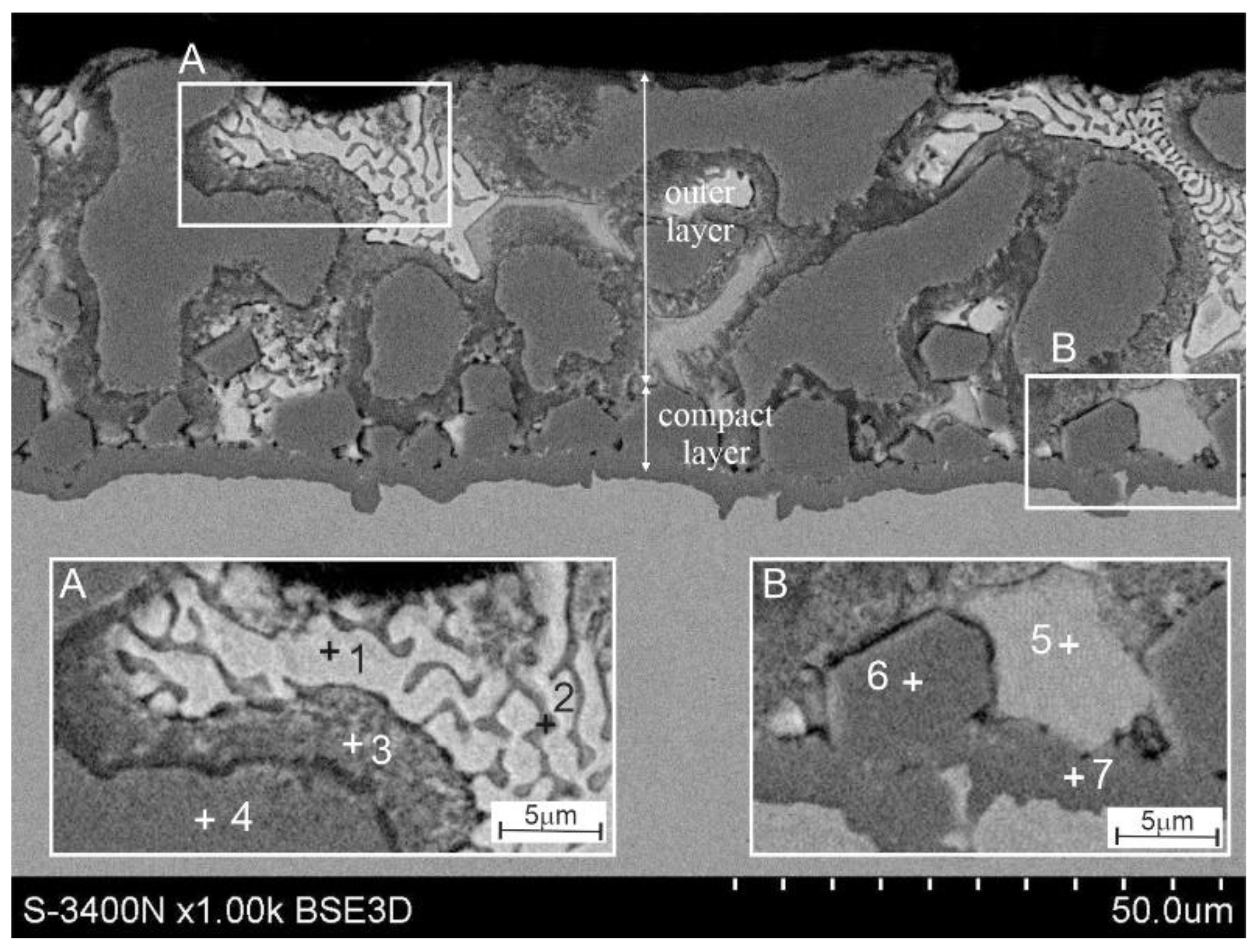
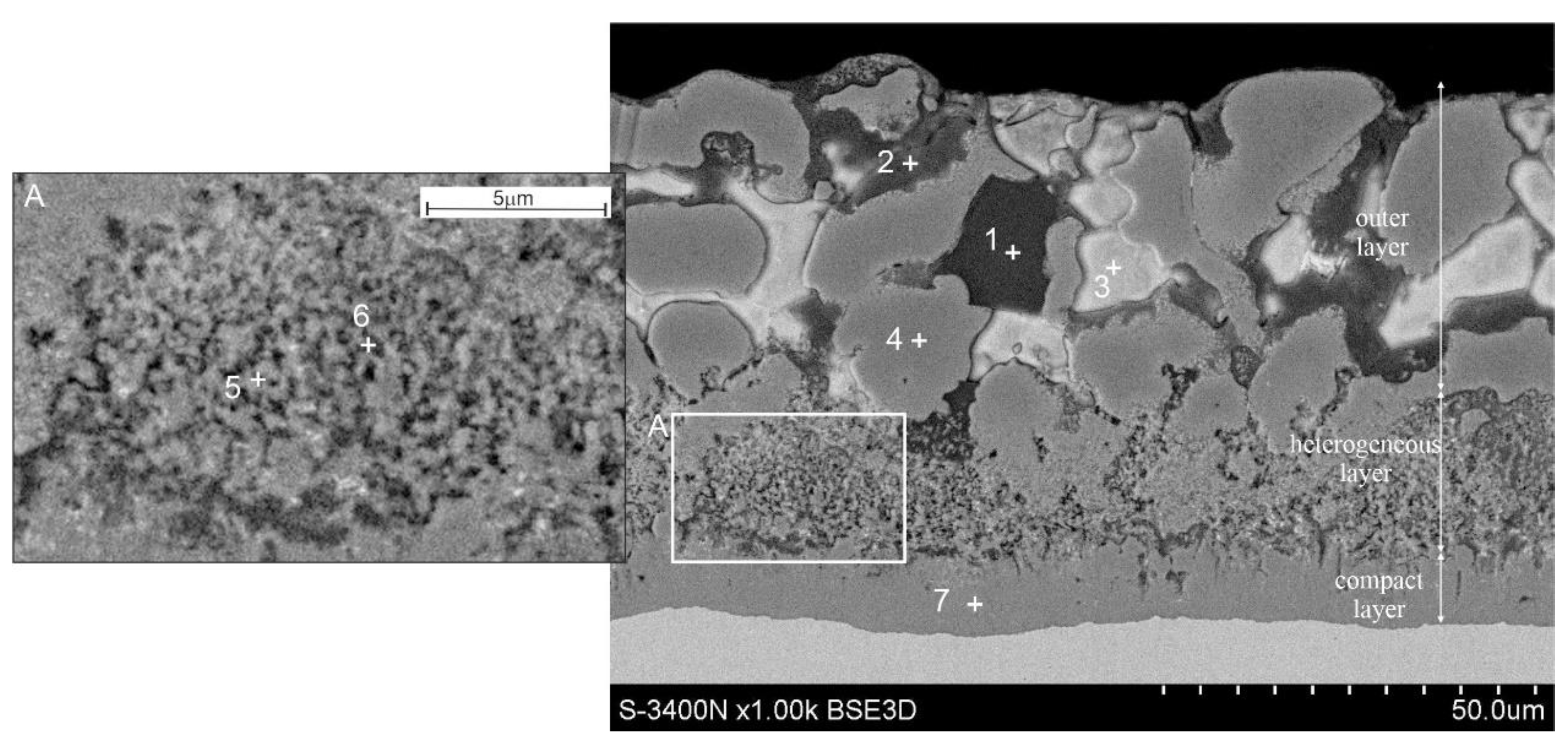
The microstructure of the coating obtained in the Zn-23Al3Mg0.2Si bath is shown in Figure 1. The percentages of the analyzed elements are given in Table 3. The presence of Al-rich dendrites can be observed in the outer layer (Figure 1, point 1). The interdendritic spaces are filled with a component rich mainly in Zn (Figure 1, point 4) and a component rich in Zn and Mg (
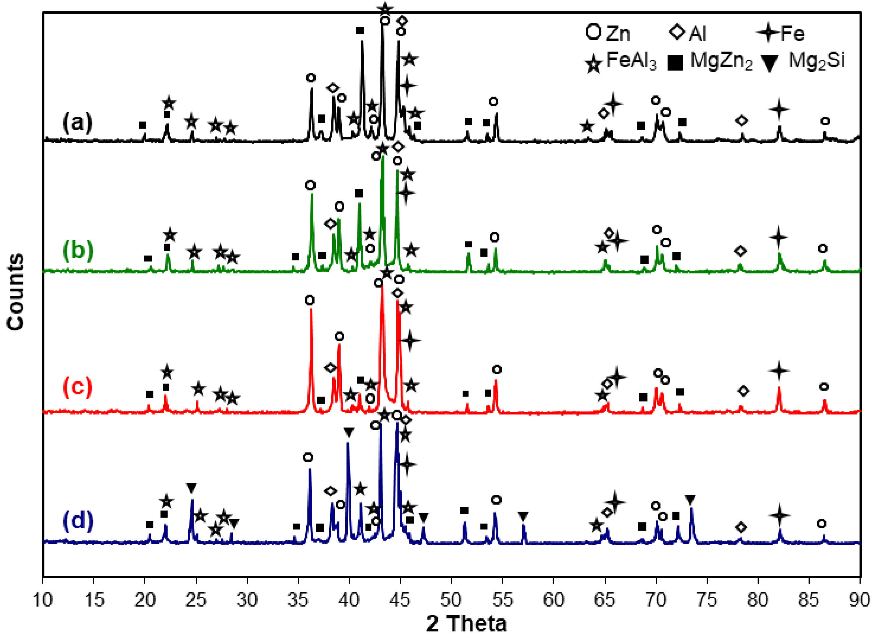
Figure 1, point 2). The XRD phase composition studies (Figure 2a) confirm the presence of the Al and Zn on the cross-section of the coating. The structural components of the coating in which Al (Figure 1, point 1) and Zn (Figure 1, point 4) are found are therefore solid solutions of these metals. XRD tests confirmed the presence of the MgZn2 intermetallic phase in the coating. It can therefore be argued, that these are interdendritic areas, in which high concentrations of Zn and Mg were found (Figure 1, point 2). This phase can also occur in the form of Zn/MgZn2 eutectic where in point 3 also a high content of Zn and Mg is observed. There are two zones in the diffusion layer of the coating. At the substrate, the compact zone contains 66.2 at.% Al and 22.1 at.% Fe as well as 5.2 at.% Zn and 6.6 at.% Si (Figure 1, point 7, Table 3). The chemical composition and the Al:Fe atomic fraction close to 3:1 indicate that it is probably the intermetallic phase of the FeAl3 system, which dissolves both Zn and Si. The presence of the FeAl3 intermetallic phase in the coating was confirmed by the diffraction pattern in Figure 2a. In the heterogeneous zone in point 5, a high concentration of Al and Fe is observed in a ratio close to 3:1 (Table 3). It also suggests the presence of the FeAl3 phase in this region. In point 6, the Fe concentration decreases, and the Zn content increases (Figure 1, Table 3). The small measurement area does not allow for a reliable determination of the chemical composition, but an increase in Zn concentration may indicate that the heterogeneity of the layer structure is filled with a zinc solution.
Increasing the Si content to 0.4 wt.% in the ZnAl23Mg3 bath does not change the phase composition of the coating. The presence of the same phases was identified in the diffraction pattern (Figure 2b) from the surface of the diagonal cut of the coating. However, the phase morphology on the cross-section of the coating clearly changes (Figure 3). There is no zone with a heterogeneous structure in the diffusion layer of the coatings. Directly on the substrate, a compact layer is formed with a content of 59.4 at.% Al and 20.6 at.% Fe and 10.6 at.% Zn and 9.4 at.% Si (Figure 3, point 7, Table 4). The Al:Fe ratio is close to the 3:1 ratio, which may indicate the presence of the FeAl3 phase in which both Zn and Si are dissolved. A similar chemical composition was found in the precipitates in point 6 (Figure 3, Table 4). These precipitates have a regular shape and are located mainly directly on the dense diffusion layer, but single precipitations are also observed in the outer layer of the coating. The diffusion layer obtained in the ZnAl23Mg3Si0.4 bath has a much smaller thickness which is caused by the influence of a higher Si content in the bath. The presence of the FeAl3 phase in the coating was clearly confirmed by the diffraction pattern shown in Figure 2b. The presence of Al-rich dendrites is visible in the outer layer of the coating (Figure 3, point 4). These dendrites are surrounded by a more heterogeneous layer (Figure 3, point 3). Both areas forming dendrites containing Al and Zn (Table 4, points 3 and 4) slightly differ in the proportion of individual metals. The chemical composition and phase composition (Figure 2b) indicate the presence of a solid solution of Al in Zn and Zn in Al. The interdendritic spaces are filled with areas containing Mg and Zn (Figure 3, point 5), as well as the Zn/MgZn2 eutectic mixture (Figure 3, points 1 and 2). The chemical composition in micro-areas in points 1 and 2 and in point 5, as well as the results of the phase composition tests (Figure 2b), confirm the presence of the solid Al solution in Zn and the MgZn2 phase in these areas.
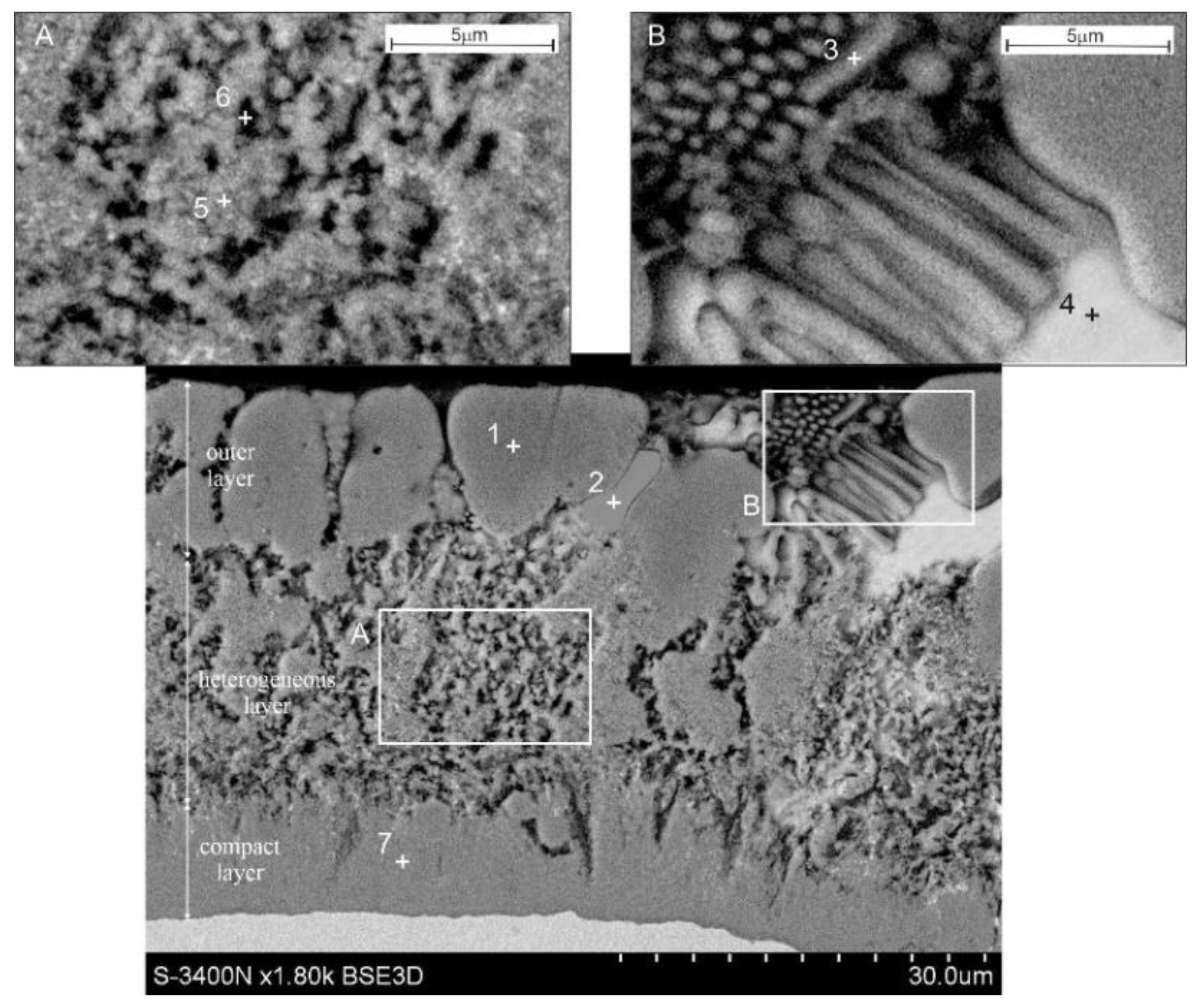
The microstructure of the coating obtained in the ZnAl23 bath containing 6 wt.% Mg and 0.2 wt.% Si is shown in Figure 4. With higher Mg content in the bath, the outer layer of the coating is formed by Al-rich dendrites (Figure 4a, point 2). On the other hand, no characteristic areas of the Zn/ZnMg2 eutectic mixture are observed. The interdendritic spaces are mainly filled with a phase containing 35.1 at.% Mg, 58.4 at.% Zn and 6.5 at.% Al (Figure 4a, point 1). The results of the XRD phase composition studies (Figure 2c) indicate that it is the MgZn2 phase. The diffusion layer shows a zonal structure. In the zone of non-homogeneous structure, there are areas with a content of 56.2 at.% Al, 18.2 at.% Fe and 15.7 at.% Zn (Figure 4c, point 3, Table 5). The heterogeneity of the structure of this layer is filled by the Zn-rich (Figure 4c, point 4) and Al-rich areas (Figure 4c, point 6). In order to clearly visualize the differences in the structure of this zone, Figure 4d presents its image obtained with the use of secondary electrons (SE). The results of the XRD phase composition studies (Figure 2c) indicate that the FeAl3 intermetallic phase and solid solutions of Al in Zn and Zn in Al occur in the diffusion layer of heterogeneous structure. On the other hand, a compact layer with a composition of 65.5 at.% Al and 21.4 at.% Fe is formed on the substrate, also including Si and Zn (Figure 4c, point 7). A similar composition can be observed in the precipitates spreading in the zone of the inhomogeneous diffusion layer (Figure 4c, point 5). When analyzing the chemical composition in micro-areas and the phase composition obtained on the cross-section of the coating, it should be stated that the areas in points 5 and 7 correspond to the FeAl3 phase in which Si and Zn dissolve.
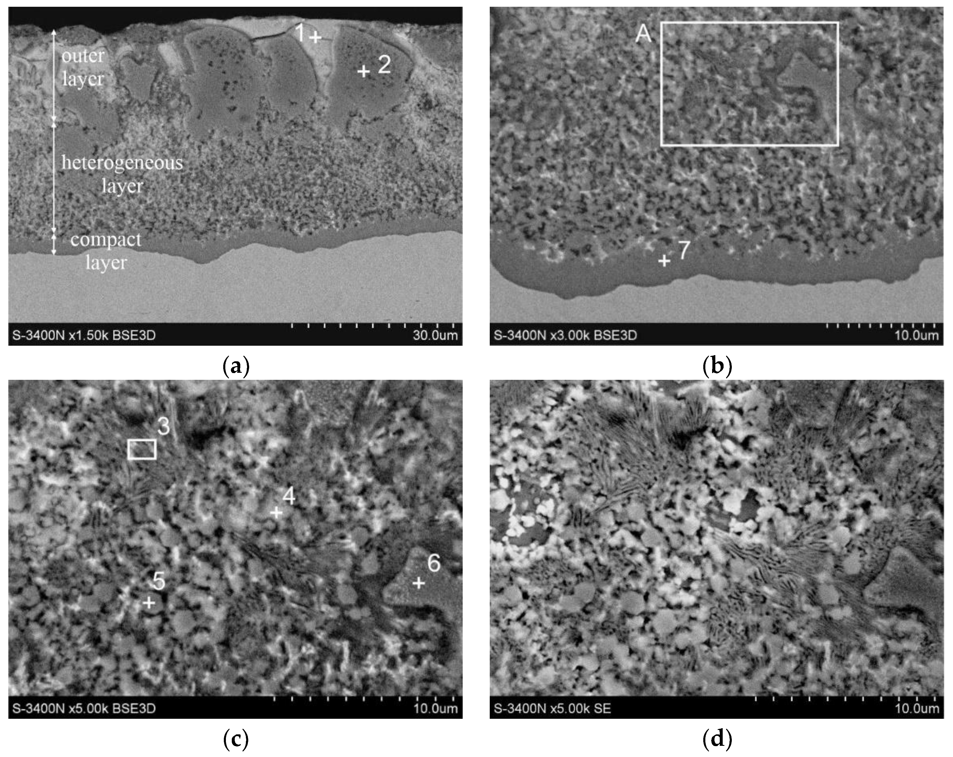
The microstructure of the coating obtained in the ZnAl23Mg6 bath with increasing the Si content to 0.4 wt.% is shown in Figure 5. The cross-section morphology itself does not differ significantly. In the diffusion layer, it can be observed the presence of dense layer on the substrate (Figure 5, point 7), which then turns into a heterogeneous zone (Figure 5, points 5 and 6). The analysis of the chemical composition in these EDS micro-areas (Table 6) and the results of the XRD phase composition tests (Figure 2d) allow us to identify these structural components of the coating as the FeAl3 phase, which dissolves Zn and Si. In the outer layer of the coating, dendrites with a significant content of Al and Zn are formed (Figure 5, point 4). Directly in their vicinity, areas with a similar chemical composition containing small amounts of Mg can be observed (Figure 5, point 2). The interdendritic spaces are mainly filled with the phase in which the content of 29.2 at.% Mg and 62.0 at.% Zn and 8.8 at.% Al (Figure 5, point 3, Table 6) was identified. The XRD phase composition studies (Figure 2d) allow the conclusion that these structural components of the coating form Al and Zn solid solutions and the ZnMg2 phase. At the content of 6 wt.% Mg and increasing the Si content in the bath to 0.4 wt.% it can be observed the interaction of these elements with each other. This leads to the formation of a new structural component in the coating in the outer layer. The chemical composition determined in point 1 (Figure 5, Table 6) and the XRD phase composition studies (Figure 2d) indicate that it is the Mg2Si phase. The Mg2Si phase was not observed in the coatings obtained in the baths with lower Mg and Si content.
The formation of the coatings in the two-component ZnAl23 bath leads to the formation of a periodic layered structure, which causes the formation of porous coatings of excessive thickness. The addition of Mg to the bath reduces this phenomenon, but does not eliminate it completely [11]. The research shows that the addition of Si to the bath helps to inhibit the formation of a periodic layered structure. The mechanism of Si interaction raises much controversy so far and is known mainly from the production of coatings in aluminum baths. Si occupies a large number of vacancies in the crystallographic network of the Fe2Al5 phase [18]. According to Riabov [19], it blocks the paths of easy diffusion of aluminum in this phase. According to another hypothesis, in the presence of Si, a triple Fe-Al-Si phase is formed, which seed and grows slower than the Fe2Al5 phase [20]. Selverian et al. [21] observed in the ZnAl55Si1.7 bath the formation of the Al-Fe-Zn-Si intermetallic compound on the substrate/coating interface, which transformed into the Fe2Al5 phase after a longer time. Similarly, Honda et al. [22] detected Zn and Si in an intermetallic compound formed on a steel substrate in a ZnAlMgSi bath. Moreover, they confirmed that the obtained intermetallic compound has the same orthorhombic crystal structure as the Fe2Al5 phase. According to the authors [22], in the Al-Zn-Si system, Fe dissolution into the liquid phase is significantly suppressed by the presence of a thin layer of Si-containing Fe2Al5 phase at the coating/substrate interface. They claim that it is very likely that the Fe2Al5 phase with dissolved Si and Zn is an Al-Fe-Si intermetallic compound.
The tests carried out in the ZnAl23 bath, regardless of the content of Mg and Si, did not confirm the presence of the Fe2Al5 phase. However, tests showed the presence of the FeAl3 phase in the coating. The research on the structure of coatings obtained in baths containing Al, Mg, and Si additives, which has been carried out so far, is not unequivocal. Ranjan et al. [23] claim that in the ZnAl21 bath containing the Si addition, the Fe2Al5 phase containing dissolved Zn and Si is formed at the interface between the coating/substrate. According to Perrot et al. [24] in the initial phase of the layer growth, the FeAl3 phase is formed, which then goes into the Fe2Al5 phase. According to Peng et al. [25], the reaction of Fe with the Zn-Al bath leads to an increase in the intermetallic phases FeAl3 and Fe2Al5 containing dissolved zinc. However, McDevitt [26] claims that in the baths with low Al content, the FeAl3 phase is first formed, which then undergoes transformation, leading to the formation of a Fe2Al5 phase layer at the boundary with the substrate. Similarly, Horstmann [27] believes that in the bath with a higher Al content, the FeAl3 phase layer grows first until it reaches the thickness at which it transforms at the border with the substrate into the Fe2Al5 phase. The lack of the Fe2Al5 phase in the tested coatings does not allow us to unequivocally exclude its presence or its transformation. However, the presence of two layers of FeAl3 and Fe2Al5 phases in the coating is the reason for stresses, which explains the formation of an unfavorable periodic layered structure. According to Selverian et al. [21], the increase of the Fe2Al5 phase layer causes a significant increase in volume. This leads to stresses at the substrate/coating interface. The increase in stress causes fracture and detachment of this phase layer as it grows. Severian et al. [21] also show the presence of stresses at the Fe2Al5/FeAl3 interface, which leads to cracking and delamination of the FeAl3 phase layer and the formation of a periodic layered structure. The tested coatings, regardless of the chemical composition of the bath, did not detach from the substrate or tend to form a periodic layered structure. Thus, it can be assumed that even the hypothetical existence or transformation of the Fe2Al5 phase in the coating, the amount of which is beyond the detectability of the research methods used, will not affect the properties of the coating.
The tests carried out have shown that Mg is present mainly in the outer layer of the coating. With the content of 3 wt.% Mg in the bath are randomly distributed areas of the MgZn2 phase or Zn/MgZn2 eutectic, which are located in interdendritic spaces. Increasing the content of Mg to 6 wt.% causes the MgZn2 phase to completely fill the interdendritic spaces. There are no Zn/MgZn2 eutectic regions in this case. Increasing the Si content to 0.4 wt.% leads additionally to the formation of randomly distributed Mg2Si phase precipitates in the outer layer. Xie et al. [28] showed that the formation of the MgZn2 intermetallic phase in coatings obtained in eutectic ZnAl baths is possible at a content above 3 wt.% Mg. Also, Liu et al. [29] claim that the MgZn2 phase is formed at higher Mg contents in the bath. According to Gao et al. [30], Mg in coatings obtained in baths with 15–55 Al wt.% and 0.5–3.0 Mg wt.% is in the elemental form and is not present in the intermetallic Zn-Mg system in the coating. By contrast, Honda et al. [22] identified the presence of both the MgZn2 phase and the Mg2Si phase in coatings obtained in the ZnAl11Mg3Si0.2 bath.

3.2. Kinetics of Growth

The relationship between the average thickness of the total coatings obtained in the ZnAl23 bath with the addition of Mg and Si and the immersion time in the bath is shown in Figure 6a. With all coatings, it can be seen that the overall thickness gain is slower with increasing immersion time. Thickness changes of coatings obtained in baths containing 3 wt.% Mg, regardless of the Si content, are similar and after an immersion time of 240 s, they reach the values of 45.12 ± 2.23 µm, respectively, with a value of 0.2 wt.% Si in the bath and 37.09 ± 2.42 µm with 0.4 wt.% Si in the bath. A similar thickness of 41.78 ± 2.09 µm has a coating obtained in a bath containing 6 wt.% Mg and 0.2 wt.% Si. On the other hand, the coating obtained in the ZnAl23Mg6Si0.4 bath has a much greater thickness. After an immersion time of 240 s, it was 74.13 ± 2.58 µm.
The coating formed in the hot dip process is formed in two steps. During immersion in the bath, the diffusion layer grows, and after the product is removed from the bath, it becomes covered with a layer of liquid melt. The diffusion layer grows as a result of simultaneous partial processes of diffusion growth, dissolution, and secondary crystallization, which determine its final thickness [31]. These regularities do not affect the formation of the outer coating layer, and its thickness depends mainly on the viscosity of the liquid alloy from which the coated product is drawn. Under these conditions, a mathematical description of the coating growth kinetics from changes in the overall coating thickness is practically impossible. The growth kinetics of the Fe-Al intermetallic layer forming the diffusion layer can be described by the equation [32]:
y = k × tn
where:
y—thickness of intermetallic layer [μm].
k—growth rate constant [μm/sn].
t—growth time [s].
n—growth-rate index.
In the kinetics equations of compact layer growth shown in Figure 6b, it can be observed that in the case of three baths the index “n” of the growth-rate is 0.53 respectively for the coating obtained in the ZnAl23Mg3Si0.2 bath; 0.52 for the coating obtained in the ZnAl23Mg6Si0.2 bath and 0.54 for the coating obtained in the ZnAl23Mg6Si0.4 bath. The “n” growth-rate index value close to 0.5 indicates that the growth of the compact layer is parabolic and thus diffusion-controlled [32]. A slightly lower value of the growth-rate index “n” 0.41 was observed for the coating obtained in the ZnAl23Mg3Si0.4 bath. Thus, the growth of the compact layer is slower here. In the structure of this coating in the transition layer, there was no zone with a heterogeneous structure (Figure 3). Direct contact of the compact layer with the liquid alloy intensifies the dissolution processes, which reduces the rate of layer growth. The values of the significantly lowest growth-rate index “n” were obtained for the heterogeneous zone. Its value is 0.14; 0.11 and 0.13 respectively for ZnAl23Mg3Si0.2, ZnAl23Mg6Si0.2 and ZnAl23Mg6Si0.4 baths (Figure 6c). This layer grows much slower due to increased dissolution due to direct contact with the liquid ZnAlMgSi alloy.

3.3. Corrosion Resistance

3.3.1. Material and Reference Research

The corrosion resistance of the coatings obtained in the ZnAl23 bath with the addition of Mg and Si was compared in the same corrosion test with the reference coating obtained in the ZnAl23Si0.4 bath without the addition of Mg. The ZnAl23Si0.4 coating was prepared by the double hot dip method on a sample of the same steel grade and with the same immersion parameters as were used for the production of coatings in baths with the addition of Mg. The chemical composition of the ZnAl23Si0.4 bath is presented in Table 7.
Before starting the corrosion tests, the structure was revealed and the coating thickness was determined on a reference sample. The reference coating obtained in the ZnAl23Si0.4 bath (Figure 7) shows a two-layer structure. Its structure is similar to the structure of the coating produced in the ZnAl bath with a eutectoid composition containing the addition of 1 wt.% Si [13]. In the outer layer of the coating, the presence of areas of solid solutions of Al in Zn (α) and Zn in Al (β) can be observed. The diffusion layer is composed of the FeAl3 intermetallic phase, the zone of which near the substrate has a compact structure, which in the outer zone turns into a heterogeneous structure. In the coating, one can also observe the occurrence of Si precipitates at the boundary between the transition layer and the outer layer of the coating.
The average thickness of the ZnAl23Si0.4 coating on the reference sample is 40.43 ± 1.32 µm. The thickness of this coating is in the comparable thickness range of the tested coatings obtained in ZnAl23MgSi baths. The list of coating thicknesses on samples for corrosion tests is presented in Table 8.

3.3.2. The Neutral Salt Spray Test

The corrosion resistance of the coatings in the neutral salt spray was assessed on the basis of unitary mass changes during the test in relation to the reference coating obtained in the ZnAl23Si0.4 bath. The change in the unitary weight of the ZnAl23MgSi coating during exposure to neutral salt spray is shown in Figure 8. During the corrosion test, all tested coatings showed mass gains. At the same time, all coatings obtained in the Mg-containing baths showed a smaller unitary weight gain compared to the reference coating obtained in the ZnAl23Si0.4 bath without the addition of Mg. The lowest weight gain during exposure to the salt spray chamber was shown by the coatings obtained in the bath containing 3 wt.% Mg. After 1500 h of test the unitary weight gain of the coating was respectively 8.65 g/m2 for the coating obtained in the ZnAl23Mg3Si0.2 bath and 8.89 g/m2 for the coating obtained in the ZnAl23Mg3Si0.4 bath. The unitary mass change curves of coatings obtained in baths containing 3 wt.% Mg during the test shows a similar course regardless of the Si content in the bath. Coatings obtained in baths containing 6 wt.% Mg show larger unitary weight gains. After completion of the corrosion test, the unitary weight gain was 9.67 g/m2 for the coating obtained in the bath containing 0.2 wt.% Si and 10.92 g/m2 for a coating obtained in a bath containing 0.4 wt.% Si. With a value of 6 wt.% Mg, greater weight gain was observed for the coating obtained in the bath with a higher Si concentration. At the same time, in the corrosion test, the reference coating obtained in the ZnAl23Si0.4 bath showed the highest weight gain. At the end of the corrosion test, it was 13.60 g/m2.
The corrosion resistance tests of alternative coatings obtained in the ZnAl23Mg bath without the addition of Si, conducted so far, showed comparable weight gains in the neutral salt spray test (NSS test) (according to EN ISO 9227). The unitary weight gain of the coating obtained in the ZnAl23Mg3 bath was 8.126 g/m2, while the coating obtained in the ZnAl23Mg6 bath was 9.31 g/m2 [33]. On the basis of the unitary mass increase of the corrosion products, it can be concluded that the Si content in the bath does not significantly affect the corrosion resistance of the coatings. However, the presence of Si in the bath is advantageous as it stabilizes the structure of the coating and reduces its thickness. The thickness of the coatings obtained in the ZnAl23Mg baths without the addition of Si was much greater and ranged from 110–120 µm [33]. At the same time, both in the case of the tested ZnAl23MgSi coatings and ZnAl23Mg coatings [33] can be noticed that the addition of 3 wt.% Mg to the bath significantly reduces the growth of corrosion products. On the other hand, higher Mg contents in the bath (6 wt.%) contribute to an increase in the amount of corrosion products on the surface of the coating, thus lowering its corrosion resistance.
Figure 9 shows the surface appearance of ZnAl23Si0.4, ZnAl23AlMg3Si0.4, and ZnAl23AlMg6Si0.4 coatings after 1500 h exposure in the salt chamber. After completion of the corrosion test, the coatings did not penetrate the substrate, which confirms their very high corrosion resistance. The coating obtained in the ZnAl23Si0.4 bath (Figure 9a) shows the highest proportion of white corrosion products on the surface. White corrosion products are identified as zinc or aluminum corrosion products [34]. It is also evident that more white corrosion products remain on the surface of the coating obtained in the bath containing 6 wt.% Mg (Figure 9c) than on the surface of the coating obtained in the bath containing 3 wt.% Mg. The surface appearance of the coatings is consistent with the results of unitary tests of mass changes and confirms the best corrosion resistance of coatings obtained in the bath with 3 wt.% Mg content. Increasing the Mg content to 6 wt.% lowers the corrosion resistance of the coating, but it is still better than the resistance of the coating obtained in the Mg-free bath. The previous tests of the corrosion resistance of traditional hot dip galvanizing coating indicate breakthroughs to the substrate, e.g. breakthroughs to the substrate of approx. Two times thicker coatings took place after 1000 h of exposure in a salt chamber [35,36]. Traditional zinc coatings show a unitary weight gain of corrosion products of 140.34 g/m2 for coatings obtained in hot dip galvanizing zinc bath with Bi [35] or even 170.38 g/m2 for coatings obtained in baths containing the total addition of Bi and Sn [36]. Thus, the corrosion of the coatings obtained by batch hot dip method in ZnAl23MgSi baths in an environment containing chloride is much slower than in the case of traditional hot-dip galvanizing coatings.

3.3.3. Corrosion Resistance in the Sulfur Dioxide Test in a Humid Atmosphere

The corrosion resistance in a humid atmosphere containing sulfur compounds was determined comparatively for coatings obtained in ZnAl23MgSi baths containing 0.4 wt.% Si and the reference coating obtained in the ZnAl23Si0.4 bath. The change in the unitary mass of the ZnAl23MgSi0.4 coating during exposure to a humid atmosphere containing sulfur compounds is shown in Figure 10.
In the initial period of the corrosion test, up to about 5–7 test cycles, all coatings showed weight gains. During this time, the highest weight gain was observed for the reference coating obtained in the ZnAl23Si0.4 bath. At the same time, the coatings obtained in the baths containing magnesium showed a smaller unitary mass gain compared to the reference coating, which proves that fewer corrosion products accumulate on their surface. At a further stage of the research, a reduction in unitary weight was observed for all coatings. Based on the observed weight loss, it can be concluded that the coating is dissolving. The course of the unitary mass change curve clearly indicates that the reference ZnAl23Si0.4 coating dissolves most intensively. After completion of the corrosion test, the unitary mass loss was 6.91 ± 0.28 g/m2 for the coating obtained in the ZnAl23Mg6Si0.4 bath and 7.72 ± 0.19 g/m2 for the coating obtained in the ZnAl23Mg3Si0.4 bath, respectively. The final unitary weight loss of the reference ZnAl23Si0.4 coating was 9.72 ± 0.29 g/m2. Thus, the addition of Mg has a positive effect on the corrosion resistance of coatings in a humid environment containing sulfur compounds. In the studied range of its concentration, its high content in the bath of 6 wt.% was the most effective in reducing the dissolution rate of the coating, but with a content of 3 wt.%, the dissolution rate of the coating was only slightly faster. The obtained results of unitary weight changes of coatings obtained in ZnAl23MgSi baths indicate their much better corrosion resistance compared to traditional zinc coatings. Corrosion tests conducted in the same environment as traditional zinc coatings showed their continuous dissolution from the beginning of the test [35,36]. However, after 30 test cycles, they showed a unitary weight loss of 24.56 g/m2 for coatings obtained in a bath containing the addition of Bi [35] and 27.46 g/m2 for coatings obtained in baths containing a total addition of Bi and Sn [36]. Final weight losses of ZnAl23MgSi coatings are more than 3 times smaller compared to traditional zinc coatings, and the initial weight loss of corrosion products may additionally delay the coating dissolution processes. After completion of the corrosion test in a humid atmosphere containing sulfur compounds, no penetration of the coating into the substrate was found, and their appearance is gray and dull (Figure 11).

3.3.4. Corrosion Resistance in the Electrochemical Test

Polarization curves of coatings obtained in ZnAl23MgSi baths and ZnAl23Si0.4 reference coatings recorded in a 3.5% NaCl solution are shown in Figure 12. The values of the corrosion current density (jcorr) were determined using extrapolation of the cathode and anode branches of the Tafel lines to the corrosion potential (Ecorr) [37]. The shape of the polarization curves for the tested coatings shows slight differences, however, one can clearly notice a shift of the cathodic and anodic branches of the coatings obtained in Mg-containing baths towards lower current density values and a shift of the corrosion potential (Ecorr) towards more negative values. It can be seen that the lowest corrosion potential (Ecorr) has coatings obtained in a bath containing 3 wt.% Mg. The corrosion potential of the coating obtained in the Zn23Al3MgSi bath (Table 9) is −865.78 and −862.21 mV (vs. NHE), respectively, with a value of 0.2 wt.% and 0.4 wt.% Si in the bath. Silicon at the content of 3 wt.% Mg in the bath does not significantly affect the value of the corrosion potential (Ecorr). Coatings obtained in a bath containing 6 wt.% Mg showed lower corrosion potential (Ecorr). With such Mg content, the effect of Si content in the bath on lowering the corrosion potential (Ecorr) was also observed. The corrosion potential of the coating obtained in the Zn23Al6MgSi bath (Table 9) is −902.56 and −915.34 mV (vs. NHE), respectively, with a value of 0.2 wt.% and 0.4 wt.% Si in the bath. A negative value of the corrosion potentials (Ecorr) indicates that these coatings provide sacrificial protection for steel [38], however, a lower potential may also indicate a higher corrosion tendency of the coating.
The coatings obtained in the bath containing Mg in comparison with the reference coating (ZnAl23Si0.4) also show a lower value of the corrosion current density (jcorr). The lowest value of the corrosion current (jcorr) has coatings obtained in a bath containing 3 wt.% Mg. Silicon in this bath does not significantly affect the value of the corrosion current density (jcorr), and its specific values were, respectively, 0.97 µA/cm2 for the coating obtained in the bath containing 0.2 wt.% Si and 0.90 µA/cm2 for a coating obtained in a bath containing 0.4 wt.% Si (Table 9). Increasing the Mg content in the bath to 6 wt.% increases the corrosion current density (jcorr) to 1.17 µA/cm2 (for 0.2 wt.% Si in bath) and 1.35 µA/cm2 (for 0.4 wt.% Si in bath). The corrosion current density (jcorr) of the reference coating (ZnAl23Si0.4) was 3.88 µA/cm. According to Faraday’s law, the corrosion current density (jcorr) characterizes the amount of mass loss [39]. Thus, its lower value for coatings obtained in the Mg-containing bath indicates an increase in their corrosion resistance.
The cause of increased corrosion resistance of coatings obtained in baths containing Al and Mg additives has not been unequivocally clarified so far. In the literature, many authors explain the increased corrosion resistance by the formation of beneficial corrosion products and their transformation. Li et al. [40] claim that there are two main corrosion products on the surface of coatings obtained in a bath containing Al and Mg additives: simonkolleite Zn5(OH)8Cl2∙H2O and smithsonite Zn5(OH)6(CO3)2. Simonkolleite Zn5(OH)8Cl2∙H2O has a very dense and compact structure [41], while smithsonite Zn5(OH)6(CO3)2 is porous and has poor adhesion to the coating surface [42]. The barrier properties of smithsonite Zn5(OH)6(CO3)2 are therefore limited. The formation of simonkolleite Zn5(OH)8Cl2∙H2O is preferential in the initial stages of corrosion [43]. The further course of the corrosion process is related to the increase in the concentration of carbonate ions caused by the dissolution of atmospheric CO2 [44], which leads to the transformation of simonkolleite Zn5(OH)8Cl2∙H2O into smithsonite Zn5(OH)6(CO3)2 [41]. The presence of Mg in the bath causes Mg ions to precipitate preferentially in relation to carbonate ions [45]. The concentration of carbonate ions in the corrosion products decreases and the conversion of simonkolleite Zn5(OH)8Cl2∙H2O into smithsonite Zn5(OH)6(CO3)2 is inhibited. As a result, the compactness of the corrosion products and their barrier protection are improved. Tsujimura et al. [8] showed that the introduction of Mg and Al ions to corrosion products results in their lower solubility and more stable barrier protection. Additionally, the presence of Si in the bath causes the Al atoms in the diffusion layer of the coating to move to the surface. It enhances the effect of inhibiting the transformation of simonkolleite Zn5(OH)8Cl2∙H2O into smithsonite Zn5(OH)6(CO3)2 [40].
The corrosion process of coatings obtained in baths containing Al additive takes place preferably in the interdendritic region rich in zinc [46]. The good corrosion resistance of Al and its alloys is due to the formation of a very adhesive insoluble and a highly passivating layer of hydrated aluminum oxide Al2O3∙3H2O on its surface [47]. The corrosive potential of aluminum in the passive state is over 1 V higher than the standard potential of the metal in the active state (E°(Al3+/Al) = −1.676 V; vs. SHE [48]). In 0.50 mol/dm3 sodium chloride solution Ecorr aluminum is −0.57 V vs. NHE. In most aqueous solutions, this metal has a similar potential value [49]. As a result, in the coating aluminum-rich dendrites are protected with a passive layer of aluminum oxide, which is chemically inactive in a wide pH range, has high hardness, and provides barrier protection [50]. Moreover, due to the potential difference, the zinc-rich interdendritic regions are more anodic (E°(Zn2+/Zn) = −0.7618 V; vs. SHE [48]) compared to Al-rich dendrites.
The conducted structural tests of ZnAl23MgSi coatings indicate that the addition of Mg and Si causes the formation of new phases in the coating. Magnesium is also located in the interdendritic region and is released in the form of the MgZn2 intermetallic phase. This phase occurs in the form of a Zn/MgZn2 eutectic mixture, or in the form of dense regions of the MgZn2 intermetallic phase. The MgZn2 intermetallic phase has a strongly anodic potential (Ecorr = −1.029 V vs. SCE [51]). The MgZn2 intermetallic phase in the coating is the phase with the lowest potential. This leads to a selective dissolution of the MgZn2 phase which provides cathodic protection (sacrificial protection) for both Zn-rich interdendritic regions as well as Al-rich dendrites. The research conducted by Han and Ogle [52] also proved that the MgZn2 intermetallic phase at the open circuit potential showed a much lower rate of Zn and Mg dissolution compared to pure metals Zn and Mg. The increased corrosion resistance is explained by the preferential dissolution of Mg, which leads to the formation of partially protective ZnO and Zn(OH)2 layers, which inhibit further dissolution of Mg.
The anodic character is also demonstrated by magnesium silicide Mg2Si (Ecorr = −1.538 V vs. SCE [51]). The precipitates of this phase were observed in the coatings obtained in the ZnAl23Mg6Si0.4 bath. The nature of the electrochemical interaction of Mg2Si in the coating is similar to the MgZn2 intermetallic phase. However, the tests carried out showed a decrease in the resistance of the coatings obtained in the ZnAl23Mg6Si0.4 bath. Ahlatci [53] showed that the corrosion loss of AlSiMg alloys proceeds through the preferential wear of the Al matrix adjacent to the primary Mg2Si precipitates. Gharbi and Birbilis [54] describe corrosion of the Mg2Si phase as selective Mg dissolution. As a result, the precipitates are richer in Si while modifying the potential to more noble values. In the AlMgSi alloys, the Si precipitations show a cathode nature (Ecorr Si = −170 mV/SCE [51]) in relation to the matrix of the Al solid solution [55], which favors intercrystalline corrosion of the alloys. A similar dissolution phenomenon of the Al matrix in contact with Si precipitates was observed in AlSi coatings in the environment containing chlorides [56]. Mg2Si, however, tends to form oxides such as SiO2 and MgO, which protect Mg2Si particles and reduce the effectiveness of galvanic connection with the matrix [57]. However, the alternation of the anodic and cathodic states causes the Mg2Si to dissolve selectively initially, followed by the dissolution of the areas around the Si-enriched particles. In particular, high Mg2Si precipitations favor pitting corrosion around itself [58]. The formation of Mg2Si precipitates in the structure of coatings obtained in ZnAl23Mg6Si0.4 baths may therefore explain the reduction in corrosion resistance compared to coatings obtained in baths containing a lower proportion of Mg and Si.
The Mg2Si or MgZn2 intermetallic phases formed by Mg are strongly anodic compared to other structural components of the coating. The corrosive potential of MgZn2 is less sensitive to pH changes in a chloride environment than the Al potential, which provides sacrificial protection in most corrosive environments. The addition of Mg to a ZnAl bath that already contains Si could potentially reduce the cathodic effect of Si by producing more anodic Mg2Si. The presence of Mg ions may also significantly modify the nature and morphology of corrosion products of coatings obtained in ZnAl baths.

4. Conclusions

The influence of Mg and Si additives on the microstructure, growth kinetics, and corrosion resistance of coatings obtained by the double dip method in ZnAl23 baths was investigated. From the results of these studies, the following main conclusions can be drawn:
  • The addition of Mg and Si to the ZnAl23 bath improved the microstructural uniformity of the coating. The diffusion layer of the coating is composed of the FeAl3 intermetallic phase. The structure of the outer layer depends on the content of Mg and Si in the bath. It consists of dendrites of an Al-rich solid solution. The formation of the MgZn2 intermetallic phase was observed in the Zn-rich interdendritic region. With the content of 3 wt.% Mg this phase locates in the Zn/MgZn2 eutectic, while with the content of 6 wt.% Mg dense interdendritic regions of the MgZn2 phase were observed. The high content of Mg and Si (6 wt.% Mg; 0.4 wt.% Si) in the bath leads to the formation of Mg2Si phase precipitation in the coating.
  • Additions of Mg and Si stabilize the growth kinetics of the coating. The course of the coating growth kinetics curve is parabolic. The high content of Mg and Si (6 wt.% Mg; 0.4 wt.% Si) in the bath leads to an increase in the thickness of the coating.
  • The addition of Mg to the bath improves the corrosion resistance of the coatings. Corrosion tests carried out in neutral salt spray, a humid atmosphere containing SO2, and tests of electrochemical parameters of corrosion showed better corrosion resistance of coatings obtained in a bath with Mg addition compared to the reference coating obtained in a bath of ZnAl23Si0.4. The increase in corrosion resistance is due to the presence of the more anodic MgZn2 phase. The high content of Mg and Si (6 wt.% Mg; 0.4 wt.% Si) in the bath may weaken the effect of increased corrosion resistance due to the formation of precipitates of the Mg2Si phase.

Funding

This research received external funding from the NCN, Poland, No. N N508 592939.

Institutional Review Board Statement

Not applicable.

Informed Consent Statement

Not applicable.

Data Availability Statement

Not applicable.

Acknowledgments

Publication supported under the pro-quality rector’s grant of the Silesian University of Technology, grant number 11/030/RGJ21/1037.

Conflicts of Interest

The author declare no conflict of interest.

References

  1. Jędrzejczyk, D. Effect of High Temperature Oxidation on Structure and Corrosion Resistance of the Zinc Coating Deposited on Cast Iron. Arch. Metall. Mater. 2012, 57, 145–154. [Google Scholar] [CrossRef]
  2. Šmak, M.; Kubíček, J.; Kala, J.; Podaný, K.; Vanĕrek, J. The Influence of Hot-Dip Galvanizing on the Mechanical Properties of High-Strength Steels. Materials 2021, 14, 5219. [Google Scholar] [CrossRef] [PubMed]
  3. Suliga, M.; Wartacz, R. The influence of the angle of working part of die on the zinc coating thickness and mechanical properties of medium carbon steel wires. Arch. Metall. Mater. 2019, 64, 1295–1299. [Google Scholar]
  4. Kriner, S.A.; Niederstein, K. Galvalume sheet: Its production, properties and application. In Proceedings of the 3rd International Conference on Zinc Coated Steel Sheet, Barcelona, Spain, 7–8 June 1991. [Google Scholar]
  5. Goodwin, F.E. An Update on Galfan. In Proceedings of the 14th International Galvanizing Conference, Munich, Germany, 9–14 June 1985. [Google Scholar]
  6. Tano, K.; Higuchi, S. Development and properties of zinc-aluminum alloy coated steel sheet with high corrosion resistance (Super Zinc). Nippon Steel Tech. Rep. 1985, 25, 29–37. [Google Scholar]
  7. Tanaka, S.; Honda, K.; Takahashi, A.; Morimoto, Y.; Kurosaki, M.; Shindo, H.; Nishimura, K.; Sugiyama, M. The performance of Zn-Al-Mg-Si hot-dip galvanized steel sheet. In Proceedings of the 5th International Conference on Zinc and Zinc Alloy Coated Steel, GALVATECH, Brussels, Belgium, 26–28 June 2001; pp. 153–160. [Google Scholar]
  8. Tsujimura, T.; Komatsu, A.; Andoh, A. Influence of Mg content in coating layer and coating structure on corrosion resistance of hot-dip Zn-Al-Mg alloy coated steel sheet. In Proceedings of the 5th International Conference on Zinc and Zinc Alloy Coated Steel, GALVATECH, Brussels, Belgium, 26–28 June 2001; pp. 145–152. [Google Scholar]
  9. Volt, M.; Bleeker, R.; Maalman, T.; van Perlstein, E. MagiZincTM: A new generation of hot-dip galvanized products. In Proceedings of the Galvanized Steel Sheet Forum, ILZRO and IZA, Duesseldorf, Germany, 30–31 May 2006; pp. 13–24. [Google Scholar]
  10. Marek, A. Hot dip Zn-5Al coatings with improved corrosion resistance of reinforcement steel. Metalurgija 2022, 61, 389–391. Available online: https://hrcak.srce.hr/265930 (accessed on 4 June 2022).
  11. Saternus, M.; Kania, H. Effect of Mg on the Formation of Periodic Layered Structure during Double Batch Hot Dip Process in Zn-Al Bath. Materials 2021, 14, 1259. [Google Scholar] [CrossRef]
  12. Mendala, J. The influence of Si addition in 55AlZn bath on the coating structures obtained in the batch hot dip metallization. IOP Conf. Ser. Mater. Sci. Eng. 2011, 22, 012005. [Google Scholar] [CrossRef]
  13. Kania, H. The structure of coatings obtained in a ZnAl23Si bath by the batch hot dip method. Solid State Phenom. 2015, 226, 155–160. [Google Scholar] [CrossRef]
  14. Kania, H. The Influence of Si Content in Steel on Growth Kinetics and Structure of Hot Dip ZnAl23Si Coatings. Solid State Phenom. 2015, 226, 133–136. [Google Scholar] [CrossRef]
  15. Nowacki, K.; Kania, H.; Wieczorek, J.; Smalcerz, A. The Properties of ZnAlMg Alloys for Batch Hot Dip Metallization. Solid State Phenom. 2016, 24, 143–148. [Google Scholar] [CrossRef]
  16. ISO 9227:2017; Corrosion Tests In Artificial Atmospheres—Salt Spray Tests; Polish Version PN EN ISO 9227:2017. Polish Committee for Standardization: Warszawa, Poland, 2017.
  17. EN ISO 6988:2000; Metallic and Other Non-Organic Coatings—Sulfur Dioxide Test with General Condensation of Moisture. Polish Committee for Standardization: Warszawa, Poland, 2000.
  18. Liberski, P. Physicochemical Basic of Rational Shaping of Aluminium Dip Coatings on Iron; Silesian University of Technology: Gliwice, Poland, 2002. (In Polish) [Google Scholar]
  19. Riabov, W.R. Aluminizing of Steel; Oxonian Press: New Delhi, India, 1985. [Google Scholar]
  20. Lainer, D.I.; Kurakin, A.K. Tekhnologiya Legkikh Metallov: Nauch.-Tekhn. Byull. (Technology of Light Alloys: Scientific and Technical Bulletin); VILS: Moscow, Russia, 1967; p. 72. [Google Scholar]
  21. Selverian, J.H.; Marder, A.R.; Notis, M.R. The effects of silicon on the reaction between solid iron and liquid 55 wt pct Al-Zn baths. Met. Trans. A 1989, 20, 543–555. [Google Scholar] [CrossRef]
  22. Honda, K.; Ushioda, K.; Yamada, W. Influence of Si Addition to the Coating Bath on the Growth of the Al-Fe Alloy Layer in Hot-dip Zn-Al-Mg Alloy-coated Steel Sheets. ISIJ Int. 2011, 51, 1895. [Google Scholar] [CrossRef]
  23. Ranjan, M.; Tewari, R.; van Ooij, W.J.; Vasudevan, V.K. Effect of Ternary Additions on the Structure and Properties of Coatings Produced by a High Aluminum Galvanizing Bath. Metall. Trans. A 2004, 35, 3707–3720. [Google Scholar] [CrossRef]
  24. Perrot, P.; Tissier, J.C.; Dauphin, J.Y. Stable and Metastable Equilibria in the Fe-Zn-Al System at 450 °C. Int. J. Mater. Res. 1992, 83, 786–790. [Google Scholar] [CrossRef]
  25. Peng, H.P.; Su, X.P.; Wang, J.H.; Li, Z. Interface reaction mechanism for galvanizing in Zn-Al baths. Chin. J. Nonferrous. Met. 2012, 22, 3168–3175. [Google Scholar]
  26. McDevitt, E.; Morimoto, Y.; Meshii, M. Characterization of the Fe-Al interfacial layer in a commercial hot-dip galvanized coating. ISIJ Int. 1997, 37, 776–782. [Google Scholar] [CrossRef]
  27. Horstmann, D. The Course of Reactions between Iron and Molten Zinc Containing Aluminum; Zinc Development Association: London, UK, 1976. [Google Scholar]
  28. Xie, Y.; Du, A.; Zhao, X.; Ma, R.; Fan, Y.; Cao, X. Effect of Mg on Fe-Al interface structure of hot-dip galvanized Zn-Al-Mg alloy coatings. Surf. Coat. Technol. 2018, 337, 313–320. [Google Scholar] [CrossRef]
  29. Liu, Y.; Tang, M.; Song, Y.; Wu, Y.; Peng, H.; Su, X.; Wang, J. Reactions of FeCr alloys with liquid zinc in hot-dip galvanizing. Surf. Coat. Technol. 2015, 276, 714–720. [Google Scholar] [CrossRef]
  30. Gao, L.; Li, Z.; Kuang, X.; Yin, F.; Ji, H. Formation of periodic layered structure during hot-dip galvanizing in Al-Zn-Mg bath. Surf. Coat. Technol. 2016, 304, 306–315. [Google Scholar] [CrossRef]
  31. Tatarek, A.; Saternus, M. Research on the phenomena of diffusion dissolution of reactive steels in a zinc bath with the addition of bismuth. Ochr. Przed Koroz. 2018, 7, 186–190. (In Polish) [Google Scholar]
  32. Su, X.; Wu, C.; Liu, D.; Yin, F.; Zhu, Z.; Yang, S. Effect of vanadium on galvanizing Si-containing steels. Surf. Coat. Technol. 2010, 205, 213–218. [Google Scholar] [CrossRef]
  33. Kania, H.; Bierońska, M. Corrosion resistance of coatings obtained in a Zn+23Al bath with Mg additions. Ochr. Przed Koroz. 2013, 10, 445–448. [Google Scholar]
  34. Zhang, X.G. Corrosion and Electrochemistry of Zinc; Springer-Verlag New York Inc.: New York, NY, USA, 2013. [Google Scholar]
  35. Kania, H.; Saternus, M.; Kudláček, J. Impact of Bi and Sn on microstructure and corrosion resistance of zinc coatings obtained in Zn-AlNi bath. Materials 2020, 13, 3788. [Google Scholar] [CrossRef] [PubMed]
  36. Kania, H.; Saternus, M.; Kudláček, J.; Svoboda, J. Microstructure characterization and corrosion resistance of zinc coating obtained in a Zn-AlNiBi galvanizing bath. Coatings 2020, 10, 758. [Google Scholar] [CrossRef]
  37. Kelly, R.G.; Scully, J.R.; Shoesmith, D.W.; Buchheit., R.G. Electrochemical Techniques in Corrosion Science and Engineering; Marcel Dekker, Inc.: New York, NY, USA; Basel, Switzerland, 2003. [Google Scholar]
  38. Dalledone, E.; Barbosa, M.A.; Wolynec, S. Zinc-55% aluminum-1.6% silicon coating compared with zinc coating. Mater. Perform. 1995, 34, 24–28. [Google Scholar]
  39. Kuz, M. Handbook of Environmental Degradation of Materials; William Andrew Publishing, Inc.: Norwich, UK, 2005. [Google Scholar]
  40. Li, S.; Gao, B.; Yina, S.; Tub, G.; Zhub, G.; Sunb, S.; Zhu, X. The effects of RE and Si on the microstructure and corrosion resistance of Zn-6Al-3Mg hot dip coating. Appl. Surf. Sci. 2015, 357, 2004–2012. [Google Scholar] [CrossRef]
  41. Volovitch, P.; Allely, C.; Ogle, K. Understanding corrosion via corrosion product characterization: I. Case study of the role of Mg alloying in Zn-Mg coating on steel. Corros. Sci. 2009, 51, 1251–1262. [Google Scholar] [CrossRef]
  42. Komatsu, A.; Izutani, H.; Tsujimura, T.; Andoh, A.; Kittaka, T. Corrosion resistance and protection mechanism of hot-dip Zn-Al-Mg alloy coated steel sheet under accelerated corrosion environment. Tetsu Hagane 2000, 86, 534–541. [Google Scholar] [CrossRef]
  43. Prosek, T.; Thierry, D.; Taxen, C.; Maixner, J. Effect of cations on corrosion of zinc and carbon steel covered with chloride deposits under atmospheric conditions. Corros. Sci. 2007, 49, 2676–2693. [Google Scholar] [CrossRef]
  44. Hosking, N.C.; Ström, M.A.; Hhipway, P.H.; Rudd, C.D. Corrosion resistance of zinc–magnesium coated steel. Corros. Sci. 2007, 49, 3669–3695. [Google Scholar] [CrossRef]
  45. Li, S.; Gao, B.; Tu, G.; Hu, L.; Sun, S.; Zhu, G.; Yin, S. Effects of magnesium on the microstructure and corrosion resistance of Zn-55Al-1.6Si coating. Constr. Build. Mater. 2014, 71, 124–131. [Google Scholar] [CrossRef]
  46. Mendala, J. Influence of the cooling method on the structure of 55AlZn coatings. IOP Conf. Ser. Mater. Sci. Eng. 2011, 22, 012004. [Google Scholar] [CrossRef]
  47. Rincón, O.; Rincón, A.; Sanchez, M.; Romero, N.; Salas, O.; Delgado, R.; López, B.; Uruchurtu, J.; Marroco, M.; Panosian, Z. Evaluating Zn, Al and Al-Zn coatings on carbon steel in a special atmosphere. Constr. Build. Mater. 2009, 23, 1465–1471. [Google Scholar] [CrossRef]
  48. Lide, D.R. (Ed.) CRC Handbook of Chemistry and Physics, 90th ed.; Taylor and Francis Group LLC: Boca Raton, FL, USA, 2010. [Google Scholar]
  49. Baszkiewicz, J.; Kamiński, M. Korozja Materiałów; Oficyna Wydawnicza Politechniki Warszawskiej: Warszawa, Poland, 2006. [Google Scholar]
  50. Moffitt, C.E.; Wieliczka, D.M.; Yasuda, H.K. An XPS study of the elemental enrichment on aluminium alloy surfaces from chemical cleaning. Surf. Coat. Technol. 2002, 137, 188–196. [Google Scholar] [CrossRef]
  51. Birbilis, N.; Buchheit, R.G. Electrochemical Characteristics of Intermetallic Phases in Aluminum Alloys. J. Electrochem. Soc. 2005, 152, B140–B151. [Google Scholar] [CrossRef]
  52. Han, J.; Ogle, K. Dealloying of MgZn2 Intermetallic in Slightly Alkaline Chloride Electrolyte and Its Significance in Corrosion Resistance. J. Electrochem. Soc. 2017, 164, C952–C961. [Google Scholar] [CrossRef]
  53. Ahlatci, H. Production and corrosion behaviours of the Al-12Si-XMg alloys containing in situ Mg2Si particles. J. Alloys Compd. 2010, 503, 122–126. [Google Scholar] [CrossRef]
  54. Gharbi, O.; Birbilis, N. Clarifying the Dissolution Mechanisms and Electrochemistry of Mg2Si as a Function of Solution pH. J. Electrochem. Soc. 2018, 165, C497–C501. [Google Scholar] [CrossRef]
  55. Zeng, F.; Wei, Z.; Li, C.; Tan, X.; Zhang, Z. Corrosion Mechanism Associated with Mg2Si and Si Particles in Al-Mg-Si Alloys. Trans. Nonferrous Met. Soc. China 2011, 21, 2559–2567. [Google Scholar] [CrossRef]
  56. Vu, A.Q.; Vuillemin, B.; Oltra, R.; Allély, C. In Situ Investigation of Sacrificial Behaviour of Hot Dipped AlSi Coating in Sulphate and Chloride Solutions. Corros. Sci. 2013, 70, 112–118. [Google Scholar] [CrossRef]
  57. Escalera-Lozano, R.; Pech-Canul, M.I.; Pech-Canul, M.A.; Montoya-Dávila, M.; Uribe-Salas, A. The Role of Mg2Si in the Corrosion Behavior of Al-Si-Mg Alloys for Pressureless Infiltration. Open Corros. J. 2010, 3, 73–79. [Google Scholar] [CrossRef]
  58. Volovitch, P.; Barrallier, L.; Saikaly, W. Microstructure and Corrosion Resistance of Magnesium Alloy ZE41 with Laser Surface Cladding by Al-Si Powder. Surf. Coat. Technol. 2008, 202, 4901–4914. [Google Scholar] [CrossRef]
Figure 1. SEM microstructure of the coating obtained in the ZnAl23Mg3Si0.2 bath.
Coatings 12 01207 g001
Figure 2. Diffractogram of the oblique ground surface of coatings obtained in the bath: (a) ZnAl23Mg3Si0.2; (b) ZnAl23Mg3Si0.4; (c) ZnAl23Mg6Si0.2; (d) ZnAl23Mg6Si0.4.
Coatings 12 01207 g002
Figure 3. SEM microstructure of the coating obtained in the ZnAl23Mg3Si0.4 bath.
Coatings 12 01207 g003
Figure 4. SEM microstructure of the coating obtained in the bath ZnAl23Mg6Si0.2: (a) coating cross-section, (b) diffusion layer (c) micro-area A—backscattered electron (BSE) image, (d) micro-area A—secondary electron (SE) image.
Coatings 12 01207 g004
Figure 5. SEM microstructure of the coating obtained in the ZnAl23Mg6Si0.4 bath.
Coatings 12 01207 g005
Figure 6. Growth kinetics of research coatings: (a) total thickness of the coating, (b) thickness of the compact layer and (c) thickness of the layer with a heterogeneous structure.
Coatings 12 01207 g006
Figure 7. Structure of the reference coating obtained in the ZnAl23Si0.4 bath for corrosion tests.
Coatings 12 01207 g007
Figure 8. Dependence of unitary changes in the mass of coatings obtained in the research baths during the neutral salt spray test.
Coatings 12 01207 g008
Figure 9. The appearance of the surface of research coatings obtained in the: (a) ZnAl23Si0.4, (b) ZnAl23AlMg3Si0.4, and (c) ZnAl23AlMg6Si0.4 bath after 1500 h of exposure in neutral salt spray test.
Coatings 12 01207 g009
Figure 10. Dependence of unitary changes in the mass of coatings obtained in the research baths during the sulfur dioxide in a humid atmosphere test.
Coatings 12 01207 g010
Figure 11. The appearance of the surface of research coatings obtained in the: (a) ZnAl23Si0.4, (b) ZnAl23AlMg3Si0.4 and (c) ZnAl23AlMg6Si0.4 bath after 30 cycles of exposure in sulfur dioxide test in a humid atmosphere.
Coatings 12 01207 g011
Figure 12. Curves of anodic and cathodic polarization of ZnAl23MgSi coatings and the reference ZnAl23Si0.4 coating in 3.5% NaCl solution.
Coatings 12 01207 g012
Table 1. Chemical composition of research baths.
BathContent [wt.%]
AlFeSiMgBiSnZn and Others
Zn0.00680.0320.0010.0020.00010.0003residue
ZnAl23Mg3Si0.223.290.0260.2192.910.00140.0028residue
ZnAl23Mg3Si0.422.840.0220.3912.830.00170.0031residue
ZnAl23Mg6Si0.222.910.01101935.890.00220.0035residue
ZnAl23Mg6Si0.423.070.0280.4126.110.00310.0036residue
Table 2. Chemical composition of S235JRG2 steel.
GradeContent [wt.%]
CSiMnSPFe and Others
G235JRG20.1380.0210.7430.00860.0088residue
Table 3. Chemical composition in micro-areas (EDS) of the coating obtained in the ZnAl23Mg3Si0.2 bath (analysis points as shown in Figure 1).
Points of MicroanatysisContent of Elements
Mg-KAl-KSi-KFe-KZn-K
wt.%at.%wt.%at.%wt.%at.%wt.%at.%wt.%at.%
1 65.882.3----34.217.7
214.830.92.64.9----82.664.2
34.912.00.92.0----94.286.0
4--3.37.6----96.792.4
5--42.159.84.46.028.219.425.314.8
6--36.956.52.13.117.813.243.227.3
7--50.466.25.26.634.822.19.65.2
Table 4. Chemical composition in the micro-areas (EDS) of the coating obtained in the ZnAl23Mg3Si0.4 bath (analysis points as shown in Figure 3).
Points of MicroanalysisContent of Elements
Mg-KAl-KSi-KFe-KZn-K
wt.%at.%wt.%at.%wt.%at.%wt.%at.%wt.%at.%
1--1.22.9----98.897.1
23.17.71.73.8----95.288.4
3--41.863.5----58.236.5
4 62.680.2----37.419.8
512.727.52.13.8----85.268.5
6--40.356.86.79.133.522.819.511.3
7--43.259.47.19.431.020.618.710.6
Table 5. Chemical composition in the micro-areas (EDS) of the coating obtained in the ZnAl23Mg6Si0.2 bath (analysis points as shown in Figure 4).
Points of MicroanalysisContent of Elements
Mg-KAl-KSi-KFe-KZn-K
wt.%at.%wt.%at.%wt.%at.%wt.%at.%wt.%at.%
117.635.13.66.5----78.858.4
20.50.768.383.6----31.215.7
3--36.756.21.31.924.618.237.423.6
40.20.56.313.9 5.25.588.380.1
5--44.060.56.38.330.019.919.711.2
60.40.664.881.4----34.818.0
70.20.351.165.54.86.133.421.412.26.6
Table 6. Chemical composition in the micro-areas (EDS) of the coating obtained in the ZnAl23Mg6Si0.4 bath (analysis points as shown in Figure 5).
Points of MicroanalysisContent of Elements
Mg-KAl-KSi-KFe-KZn-K
wt.%at.%wt.%at.%wt.%at.%wt.%at.%wt.%at.%
150.353.9--49.746.1----
2--64.681.7----35.218.3
314.229.24.88.8----81.162.0
40.81.067.883.1----31.415.9
50.61.621.839.9 77.458.5
60.20.337.255.92.73.925.118.234.821.6
70.10.154.169.83.34.136.322.66.23.3
Table 7. Chemical composition of reference ZnAl23Si0.4 bath.
BathContent [wt.%]
AlFeSiMgBiSnZn and Others
ZnAl23Si0.423.140.0210.3970.00030.00170.0026residue
Table 8. The average thickness of coatings on samples for corrosion tests.
The Thickness of Coatings (µm)
ZnAl23Si0.4ZnAl23Mg3Si0.2ZnAl23Mg3Si0.4ZnAl23Mg6Si0.2ZnAl23Mg6Si0.4
40.43 ± 1.3234.54 ± 1.8731.42 ± 1.8233.81 ± 1.7242.08 ± 2.24
Table 9. Electrochemical parameters of corrosion of tested coatings in 3.5% NaCl solution.
Type of CoatingEcorr (mV vs. NHE)jcorr (µA/cm2)
ZnAl23Si0.4−19.333.88
ZnAl23Mg3Si0.2−865.780.97
ZnAl23Mg3Si0.4−862.210.90
ZnAl23Mg6Si0.2−902.561.17
ZnAl23Mg6Si0.4−915.341.35
Publisher’s Note: MDPI stays neutral with regard to jurisdictional claims in published maps and institutional affiliations.

