Article

Corrosion Protection Efficacy of the Electrodeposit of Poly (N-Methyl Pyrrole-Tween20/3-Methylthiophene) Coatings on Carbon Steel in Acid Medium

by
Florina Branzoi
*,
Marius Alexandru Mihai
and
Simona Petrescu
Electrochemistry and Corrosion Department, Romanian Academy, Institute of Physical Chemistry “Ilie Murgulescu”, 202 Splaiul Independentei, 060021 Bucharest, Romania
*
Author to whom correspondence should be addressed.
Coatings 2022, 12(8), 1062; https://doi.org/10.3390/coatings12081062
Submission received: 27 June 2022 / Revised: 15 July 2022 / Accepted: 25 July 2022 / Published: 27 July 2022

Abstract

:
In this study, poly(N-methylpyrrole-Tween20/3-methylthiophene) coatings were electrodeposited on carbon steel type OLC 45 by electrochemical techniques in oxalic acid solution. Surfactant Tween 20 as a dopant ion employed during electropolymerization can have an important influence on the corrosion protection of this coating by obstructing the penetration of aggressive sulfate ions. The new composite coatings have been analyzed electrochemically, spectroscopically and morphologically by cyclic voltammetry, Fourier transform infrared spectroscopy (FT-IR) and scanning electron microscopy (SEM) methods. Corrosion protection consideration of PNMPY-TW20/P3MT-coated OLC 45 has been analyzed by potentiostatic and potentiodynamic polarization, open circuit potential and electrochemical impedance spectroscopy (EIS) measurements in 0.5 M H2SO4 medium. The corrosion rate of PNMPY-TW20/P3MT-coated OLC 45 has been indicated to be ~10 times reduced compared to uncoated OL 45, and the corrosion protection efficiency of the coating is above 90%. The greatest efficacy is achieved by PNMPY-TW20/P3MT composite by electrodeposition at 5 mA/cm2 and 3 mA/cm2 current densities applied and at 1200 mV potential applied in 5:1 and 3:5 molar ratios. The PNMPY-TW20/P3MT coating realized by the galvanostatic method exhibited a non-damaging surveying after 96 h of immersion in the aggressive medium, further verifying its excellent protection capacity. The consequences of the corrosion experiments clearly divulged that PNMPY-TW20/P3MT coatings ensure a very good anticorrosion protection of OLC 45 in aggressive medium.

1. Introduction

In recent years, the protection of metal surfaces by using conducting polymers as developed coating materials has become one of the most captivating research domains [1,2,3,4,5,6,7,8,9]. Corrosion of metals and their alloys represents an appreciable economic and industrial concern. In industrial procedures, the metal surfaces employed are exposed to highly aggressive acids and alkali environments, which provoke substantial corrosion and deterioration. Thus, the objectives of electrodeposition of these coatings on different metals and their alloys and assessing their corrosion protection features have led to increasing attentiveness. Conducting polymers, such as polyaniline, polypyrrole, polythiophene and its derivatives, are the most frequently utilized for protective coatings [4,5,6,7,8,9,10,11,12,13]. Thus, integration of hydrophobic functionary groups is assumed to enhance the polymer protection performance. Poly (N-methylpyrrole and 3-methylthiophene) could be one of the polypyrrole and polythiophene derivatives with greater protection effects than the base conductive polymer owing to the methyl group hydrophobicity [14,15,16,17,18,19,20]. These organic coatings usually increase the strength of metals against various aggressive agents. The efficiency of these protecting films ensures that a barrier to the substrate can be affected by diversified elements: the type of conducting polymer, the electrodeposition procedure that has been utilized on the electrode’s surface and the corrosive solution [16,17,18,19,20,21,22,23,24,25]. The employment of electrochemical polymerization, technical, nanostructured coatings, implementing organic or inorganic coatings and cathodic and anodic protection are procedures for the anticorrosion features of metallic materials [4,5,6,20,21,22,23,24,25,26,27,28,29,30,31,32,33]. Metallic materials are widely used in diversified sectors, such as: chemical manufacturing, oil making and refining, the construction industry, machinery equipment, technological equipment and marine practices; this has improved the investigation of corrosion defense in differing aggressive media [34,35,36,37]. Conversely, corrosion is a real element in the deterioration of industrial structures: a substantial number of tests have been carried out to discover mechanisms to minimize corrosion and wear costs. Several explorations accomplished for defense of metallic materials in the sector of engineering established the employment of composite polymer coatings as the most effective and plain manner of obstructing the degradation of such materials in aggressive environments [37,38,39,40,41,42]. The obtaining of new polymeric composites from varied monomer molecules was achieved to improve the physico-chemical properties of polymer coatings, to enhance lengthy interval protection, for increased adherence and to improve the electrochemical properties [28,29,37,38,39,40,41,42,43]. One of the essential problems regarding the utilization of conducting polymers for metallic materials corrosion protection is their water permeability, which can result in existing corrosive compounds being transferred onto the metal area. Conducting polymers are efficient regarding rapid doping and de-doping with an overly high charge density and, as a result, are possible active materials for employment in numerous electrochemical applications [41,42,43,44,45]. Conducting polymers also have an intriguing molecular pattern owing to their significant ability to amend properties when operated by an electric signal. These recently developed materials provide meaningful prospects for a broad domain of new applications, such as capacitors, sensors, solar cells, batteries, membranes, nanoelectronics and corrosion protection coatings [2,3,4,5,6,7,8,9,10,27,28,29]. The composites established from conducting polymers have a succession of particular properties, such as enhanced chemical steadiness, thermostability, being environmentally friendly and a suitable barrier being assured. The dopant ions integrated into conducting polymers exert influence on both the polymerization process and the characteristics of the obtained polymers. The dopant ion utilized throughout electrodeposition can have a pronounced impact on the ion-exchange selectiveness number of conducting polymers. In certain occurrences, the incorporation of greater hydrophobic dopant ions, e.g., triton X100, tween 20, results in the constitution of a polymer capable of cation exchange with a wholly hydrophobic character [37,38,39,40,41,42,43,44,45,46]. It has been determined that the electrochemical and physical characteristics of polymers are remarkably influenced by the kind of dopant and electrolyte concerning the electropolymerization process [43,44,45,46]. The goal of this study is to obtain novel conductive polymers appropriate for anticorrosion protection of common metals. Moreover, developing suitable electrochemical polymerization methods to achieve compact, uniform, powerful adherent composite coatings over metals’ surfaces is part of the focus of this paper. Another interest domain is obtaining and optimizing novel composite polymers with excellent anticorrosion features for some metals and their alloys in aggressive media. These new composite coatings should be distinct from those presented in the literature, and they should have enhanced efficiency. This work involves the electrosynthesis, electrochemical and spectroscopic examination of the new composite poly (N-methyl pyrrole-Tween 20/3 methylthiophene) and the corrosion behavior of this new composite. The novel composite (PNMPY-TW20/P3MT) has been applied over the OLC 45 surface by galvanostatic and potentiostatic procedures from synthesis solutions of 0.1 M N-methyl pyrrole, 0.1 M 3-methylthiophene and 0.03 M Tween 20 with 0.3 M oxalic acid. Investigation of the new composite coatings has been accomplished by cyclic voltammetry, FT-IR spectroscopy and scanning electron microscopy (SEM) methods. Corrosion experiments of PNMPY-TW20/P3MT deposited on OLC 45 have been investigated by potentiostatic, potentiodynamic polarization and electrochemical impedance spectroscopy (EIS) procedures in 0.5 M H2SO4 media. This study is a continuation of previous work on the acquisition and evaluation of some composite coatings suitable for protection of metallic materials against corrosion in an aggressive medium.

2. Experimental

Materials and Methods

In present study, a carbon steel type of OLC 45 sample was employed as a working electrode for the corrosion examination. The chemical composition of working electrode type OLC 45 is: C% 0.48, Si 0.03%, Mn 0.79%, Fe% 98.32, P% 0.02, S% 0.025, Al% 0.027, Ni % 0.05, Cr% 0.06, Cu% 0.18, Sn% 0.012 and As% 0.006. The aggressive environment has been 0.5 M H2SO4, which was obtained by dilution of AG 96% H2SO4 (from Merck) by bi-distilled water. All chemicals were reagent grade, N-methylpyrrole (NMPY), 3-methylthiophene (3 MT), Tween-20 (Tw-20) have been provided from Sigma-Aldrich (USA) (>98%) and acid oxalic dehydrate was procured from Merck (USA) (>97%). In all experiments, the synthesis solutions were realized by using bi-distilled water: NMPY 0.1 M, Tw-20 0.03 M and 3 MT 0.1 M in oxalic acid 0.3 M. The electrodeposition and examination of new composite coatings were realized by employment a single-partition cell by the conventional three electrodes set-up at room temperature. The electrochemical cell was connected at a VoltaLab potentiostat linked to PC working VoltaMaster 4 software (Version 7.09). A saturated calomel electrode (SCE) was employed as the reference electrode and a platinum sheet as an auxiliary electrode. The working sample is carbon steel type OLC 45 by cylindrical shape and with an area of 0.5 cm2. This format is chosen since it ensures a considerable zone and without edges. The working specimen has been mechanically smoothed by a series of emery papers with various measures (200–4000 grid) up to mirror-gloss. Afterwards, the OLC 45 sample was cleaned in benzene to eliminate all traces of grease (remainders); after that, it was washed in doubly distilled water, dried at room temperature and ushered in the electrochemical cell. All experiments were realized at 25 °C in atmospheric oxygen without agitation. Previous to electrodeposition of polymer coatings, the OLC 45 sample has been passivated in 0.3 M H2C2O4 solution by cyclic voltammetry on the range potential of −600 mV up to 1200 mV for SCE at a potential scan sweep 20 mV/s by applying 4 cycles. The poly (N-methylpyrrole-Tween-20/3 methylthiophene) coatings have been deposited by the electropolymerization of 0.1 M N-methylpyrrole, 0.03 M Tween-20, 0.1 M 3-methylthiophene and 0.3 M oxalic acid onto OLC 45 passivated substrate by galvanostatic and potentiostatic procedure (Scheme 1). The electrodeposition was acquired by galvanostatic process at current densities 3 mA/cm2 and 5 mA/cm2 and potentiostatic practice at 1.2 V and 1.4 V applied constant potential with varied molar ratio (1:1, 3:5 and 5:1), and the depositing has been allowed for 20 and 30 min. The adherence of the coating was accomplished by the “standard sellotape test”, which describes cutting the film into small squares, sticking the tape and then stripping it (Scheme 2). The proportion adherence was realized with taking into consideration the fraction of the number of the remaining adherent coating squares at the total number of the squares.
The electroactivity of PNMPY-TW20/P3MT coatings was analyzed in 0.3 M H2C2O4 solution by cyclic voltammetry means. The corrosion experiments of uncoated and PNMPY-TW20/P3MT-coated electrodes were considered by procedures of potentiodynamic polarization and electrochemical impedance spectroscopy (EIS) in 0.5 M H2SO4 media. The lengthy-period corrosion experiments of the PNMPY-TW20/P3MT coatings were as well at differing intervals up to 120 h in 0.5 M H2SO4 medium by the electrochemical techniques. Analysis of the Tafel polarization curves was effectuated by sweeping the potential through the cathodic to the anodic potential in the potential interval from −800 mV to −100 mV (SCE) at a scan rate of 2 mV/s for OLC 45 samples. All potentials have been registered versus the SCE. Electrochemical impedance spectroscopy tests were executed into the frequency range of 100 kHz to 0.04 Hz, and signal amplitude has been 10 mV at the open circuit potential of PNMPY-TW20/P3MT-coated and uncoated electrodes. A potentiostat/galvanostat VoltaLab PGZ 402 system has been utilized in all electrochemical tests. The composition of PNMPY-TW20/P3MT polymeric coating was executed with Bruker optics FT-IR spectrometer (Bruker, Ettlingen, Germany) by ATR attachment (Pike, USA, with a diamond and ZnSe crystal) in the spectral field 4000–650 cm−1 at a resolution 4 cm−1. Morphologies of PNMPY-TW20/P3MT-covered OLC 45 substrates have been considered by scanning electron microscope (SEM, FEI Quanta 3D FEG model, Brno, Czech Republic)). Specimens’ morphology studies were carried out by SEM in a dual beam FEI Quanta 3D FEG model, working in high vacuum means with an accelerating voltage of 5 to 10 kV. Minimal samples preparation consisted of immobilizing the electrodes on a double-sided carbon tape, without coating.

3. Results and Discussion

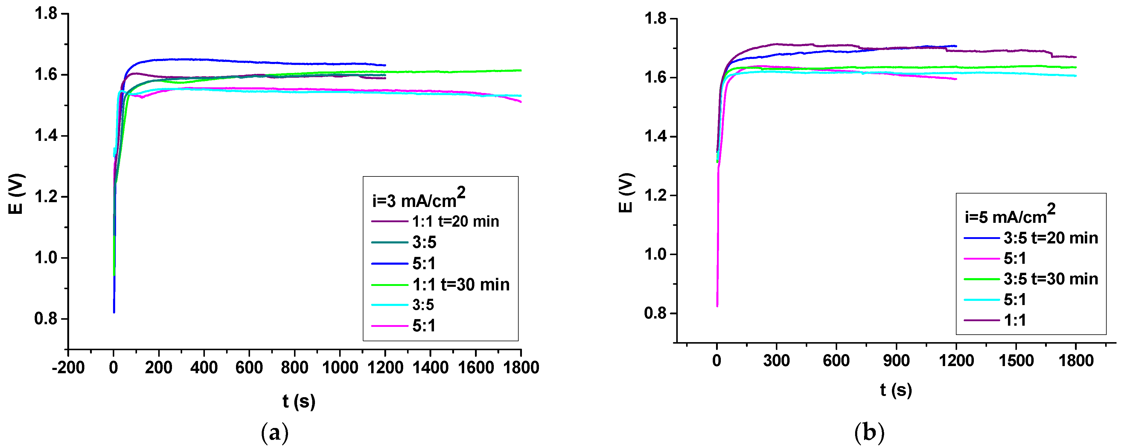
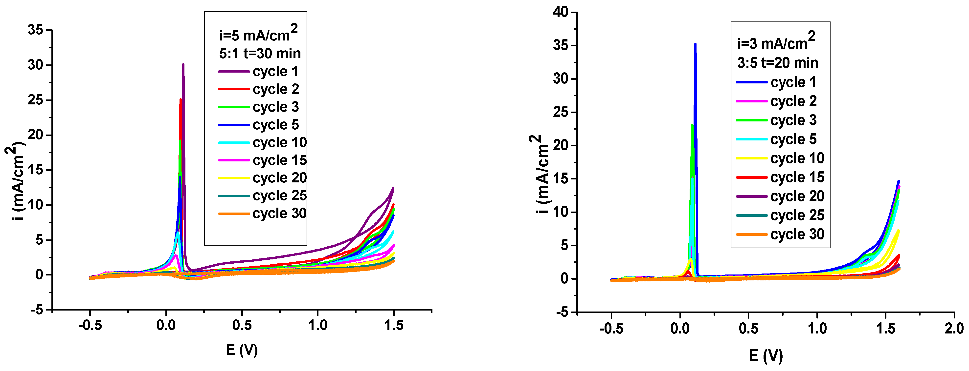
3.1. Electrodeposition PNMPY-TW20/P3MT Coating

Previous to the deposition of PNMPY-TW20/P3MT, the OLC 45 samples were first polarized in 0.3 M aqueous oxalic acid solution by cycling the potential electrode; this process was introduced in previous papers [10,14]. The insoluble species acquired from the passivation process constitute iron oxides and iron oxalates, such as Fe (Ox) (FeO, Fe2O3) and FeC2O4, which hinder metal dissolving without obstructing the electropolymerization practice. The passivated sample OLC 45 under the electrodeposition mechanism was also submitted in the literature [10,11,12,13,14,15,16,17,18,19,20,21]. Through perfecting the polymerization characteristics, we can acquire polymeric layers of PNMPY-TW20/P3MT that have a considerable anticorrosion protection outcome. The electropolymerization of NMP and 3MT monomers was acquired over the substrates of the passivated OLC 45. Subsequent to passivation, the electrodeposition of the monomers was instituted without amending the polymerization features. An appreciated electrodeposition involves the attainment of a passive layer, which could be efficacious to obstruct the dissolution of the oxidizable metal without blocking the admittance of the monomer and its ensuing oxidation. The ending effect is to yield a uniform composite film, dense, uniform and adhesion at the electrode’s substrate. The polymeric composite PNMPY-TW20/P3MT was effectuated by galvanostatic characteristics from 0.3 M H2C2O4, 0.1 M N-methylpyrrole, 0.03 M Tween 20 and 0.1 M 3-methylthiophene at current densities 3 mA/cm2 and 5 mA/cm2 and by the potentiostatic process at 1.2 V and 1.4 V applied potential with different molar ratios. The electrodeposition was allowed for 20 min and 30 min. Figure 1 depicts the “potential–time” curves obtained by the forming of the polymeric film, such as: composite poly (N-methylpyrrole-Tween 20/3-methylthiophene) on carbon steel OLC 45 (PNMPY-TW20/P3MT/OLC 45) at various applied current densities with varied molar ratios. Further, with the oxidation intervals of 1200 s and 1800 s, the primary shape of the “potential–time” curves throughout the polymer electrodeposition process denotes that the polymer electrodeposition has been made by “nucleation and growth” on the OLC 45 surface [10,13,14,15,16,17,18,19,20,21].
Figure 1 at 5 mA/cm2 and 3 mA/cm2 shows current densities at several molar ratios, shorter induction interval results and an induction period as small as 20 s has been remarked on regarding the electropolymerization of NMPY and 3MT composite films, and its value decreased by increasing the molar ratio and nucleation potential. The polymerization potential is various among 1.6 V and 1.7 V versus SCE for applied current densities: 3 mA/cm2 and 5 mA/cm2 with 1:1, 3:5 and 5:1 molar ratios for NMPY-Tw20 and 3MT. The surfactant Tween 20 dopant ion used in electropolymerization (presented in methylpyrrole) can exhibit a relevant influence on the ion improvement selectivity, ensuring polymer conductivity. The coatings attained at different current densities, i.e., 5 mA/cm2 and 3 mA/cm2, own the densest and adherent countenance, and they have been appreciated for the forming of good-quality PNMPY-TW20/P3MT/OLC 45 coatings. The visual monitoring of the OLC 45 specimen surface subsequent deposition reveals the obtaining of a black-colored PNMPY-TW20/P3MT/OLC 45 film. The polymeric composite coating is uniform, dense and adherent onto the OLC 45 electrode surface. The coating adherence assessed by “the standard sellotape” has been determined to be ~85%.
From Figure 2, it can be noticed that the “current density–time” curves attained throughout the forming of PNMPY-TW20/P3MT coatings on OLC 45 at 1.2 and 1.4 V applied potential with varied molar ratios. Subsequent to the oxidation time of 1200 s and 1800 s, the primary shape of the “current density–time” curves during the polymer deposition assessment exhibit that the polymer depositing was provided by nucleation and growth over the sample (OLC 45) surface [10,16,17,18,19,20,21,22]. At the beginning, the current fell abruptly owing to electro-adsorption of the electrolyte and NMPY-3MT monomers. Following soon after 50 s, the current increased, and this is owed to the dissolution of the passive film and constitution of the polymer on the OLC 45 substrate. In the ending period, the current remained steadfast as the polymer layers were acquired over the OLC 45 surface. The transitory modification of the higher part is linear with the nucleation time change, the electrochemical control and the distinction in the molar ratio of NMPY:3MT. Whenever the applied potential was 1.4 V and 1.2 V at 5:1 and 3:5 molar ratio, the current was nearly constant at 2 mA/cm2, 4 mA/cm2 and 6 mA/cm2; the current has been greater than other potentiostatic polymerization circumstances and the achieved layers have been dense and adherent. The electrochemical properties, such as the applied potential, have been determined to exert a considerable impact on the induction period. It should be specified that, at 1.4 V and 1.2 V, applied constant potential at 5:1 and 3:5 for the NMPY:3MT molar ratios has a small induction time for acquirement of an electrodeposited coating, and it has been advantageous for the forming of superior-feature PNMPY-TW20/P3MT coatings. From Figure 2, it can be noticed that the deposition at 1.2 V applied constant potential at 1:1 for the NMPY:3MT molar ratio, has a lengthier induction period for achievement of PNMPY-TW20/P3MT coating and has been less favored for the constitution of high-quality coatings. The visional examination of the OLC 45 electrode subsequent to electrodeposition displays the forming of a black PNMPY-TW20/P3MT film. The coating is uniform, compact and adherent over the OLC 45 sample. The coating adherence assessed by “the standard sellotape” has been determined to be ~80%.

3.2. Electrochemical Characterization of PNMPY-Tw20/P3MT Composite Coating

The electrochemical behavior of the PNMPY-TW20/P3MT composite covered on the OLC 45 sample in 0.3 M H2C2O4 solution without a monomer is displayed in Figure 3 in the potential domain of −0.5 and +1.5 V versus SCE and the sweep rate of 20 mV/s.
Studying Figure 3, it is plain that the electrochemical comportment of coating film is influenced by the number of cycles and the electrodeposition-specific features. The steadfastness of whatever conducting polymer in reduced and oxidized states is a significant feature for numerous practices. The principal ground that determines the duration of life of a polymer is the chemical steadiness of the matrix itself. The steadiness of PNMPY-TW20/P3MT coating was appraised by cyclic voltammetry (above 20 cycles) in the oxalic acid solution without monomers (see Figure 3). The cyclic voltammetry technique was accomplished in the extensive potential range in order to explore all the physical and electrochemical attributes of the polymeric layers. The attendance of the oxidation and reduction wave subsequent to more than 20 cycles indicates the stability of these electroactive films [4,5,6,10,14,15,16,17,18,19,20,21,22].Therefore, these layers could be cycled many times from the oxidized and reduced property without meaningful decomposition of the composite coatings; the current density lessens with either cycle and, lastly, attains a constant value.

3.3. FT-IR Studies

The PNMPY-TW20/P3MT/OLC 45 coatings’ compositions were studied by FT-IR spectroscopy (see Figure 4) at a resolution of 4 cm−1 (over four scans) in the spectral interval 4000–650 cm−1. FT-IR means can be utilized to emphasize the type of bonding used to obtain a novel polymeric composite. The typical peaks in the transmittance spectrum of PNMPY-TW20/P3MT/OLC 45 coatings are presented in Figure 4. The FT-IR results explain the attendance of the significant absorption bands observed in PNMPY and P3MT electrodeposited over the OLC 45 surface.
The significant peaks in the transmittance spectrum of NMPY (monomer) and 3MT (monomer) that have been exhibited in Figure 4a,b are the result of the spectrum of NMPY, presented in Figure 4a, where the important particular characteristics of bands for the aromatic ring in NMPY are plain to 1558 and 1442 cm−1 for C=C stretching, being obviously noticed. The peak at 2928 cm−1 is assigned to the CH3 stretch of N-methylpyrrole units. The summit around 1254 cm−1 is ascribed to the C-N stretching vibration of the pyrrole ring. The distinguishing bands at 1362 and 1312 cm−1 are assigned to N-H stretching vibration of the pyrrole ring. The band placed at 1673 and 1622 cm−1 is reported at the C=C stretching. The peaks, which can be established as “in plane and out of plane” of the CH chains at 1143, 1062 and 616 cm−1, are remarked upon in the polymer. In the spectrum of 3MT in Figure 4b, the bands suitable to the asymmetric and symmetric C=C stretching vibrations of the 3MT ring are noticed at 1559 cm−1 and 1452 cm−1. The peak at 2973 cm−1 is allocated to the CH3 stretch of 3-methylthiophene parts. The band arising at nearly 1034 cm−1 and 757 cm−1 exhibits the C-S-C stretching vibration of the thiophene ring. The transmittance spectra of PMPY-Tw20/P3MT/OLC 45 electrodeposition by galvanostatic and potentiostatic techniques are described in Figure 4c,d. The bands noticed at 3460 and 3110 cm−1 are allocated to the N-H stretching vibration in the polymer. The peaks appearing at around 3450 and 3420 cm−1 correlate with the OH stretch of the counterions. The peaks at about 2930–2921 cm−1 are ascribed to the CH3 stretch of N-methylpyrrole elements. The meaningful attributes of the peaks of the aromatic ring in PNMPY are evident at 1556 and 1461 cm−1 for C=C stretching, with the attendant evidently established. The attendance absorption bands situated at 1563, 1544, 1475 and 1460 cm−1 are revealed in the stretching vibration of the quinoid rings (Figure 4c,d). The peak at around 1237 cm−1 represents the C-N of the pyrrole ring. The peaks placed at 1380 and 1319 cm−1 are attributed to N-H stretching vibration of the methylpyrrole ring; the bands at 1650 and 1620 cm−1 are connected to the C=C stretching. In the spectrum of composite coating, the bands suitable to the asymmetric and symmetric C=C stretching vibrations of the 3-methylthiophene ring are mentioned at 1560 cm−1 and 1468 cm−1 (Figure 4c,d) [10,14,15,16,17,18,19,20,21,22]. The bands revealing near 1040 cm−1 and 767 cm−1 introduce the C-S-C stretching vibration of the 3-methylthiophene ring. The band at about 1522 cm−1 is reported for the C=C stretching vibration. The bands at about 1450 and 1320 cm−1 are linked to the “stretching vibration” of the CH2 and CH3 components in the Tween 20 surfactant. The occurrence of the bonds C=O and CH is displayed by stretching modes at 1682 cm−1 and 1264 cm−1, which have been most probably bonded by the protection of the surfactant in the polymer matrix. The small summits at 1120, 1080, 965 and 830 cm−1 are ascribed to C-O-C vibration in (CH2CH2O)n of the surfactant, such as the dopant of the composite polymer (Figure 4c,d).The peaks at around 1160, 858, 778 and 1006 cm−1 are allocated at the ”in-plane” and “out-plane” C-H of the aromatic rings and to “out of plane” vibration of C-H doped with PNMPY in oxalic acid solution (Figure 4c,d) [16,17,18,19,20,24,25,26,27,28,29]. The peak differentiating the “in plane” and “out of plane” of the N-H chains at 1034, 1152 and 640 cm−1 is assumed to be appropriate in the PNMPY-Tw 20/P3MT/OLC 45 composite layer. By comparing Figure 4a–d, it can be supposed that the PNMPY-Tw20/P3MT composite polymer is deposited on the OLC 45 surface. The bands attending to the monomer spectrum (MPY and 3MT) are displayed at the transmittance spectrum of the composite covered onto the carbon steel surface.

3.4. Electrochemical Evaluations

3.4.1. Potentiodynamic Polarization Procedure

The protection properties of the obtained PNMPY-TW20/P3MT/OLC 45 composite coating were considered in 0.5 M H2SO4 by a potentiodynamic polarization procedure and electrochemical impedance spectroscopy. The polarization curves of uncoated and PNMPY-TW20/P3MT coated OLC 45 in 0.5 M H2SO4 environment are exhibited in Figure 5, Figure 6 and Figure 7. Further, polarization comportment of the OLC 45 electrode was elaborated by those acquired to PNMPY-TW20/P3MT-composite-covered carbon steel achieved by the galvanostatic and potentiostatic process at various current densities and potentials with diverse molar ratios and varied deposition times. In this study, one of the preferred procedures for the protective action of carbon steel in aggressive solutions is the employment of the composite coatings, which explore the corrosion of the anodic or cathodic process and both. The PNMPY-TW20/P3MT-composite-coated surfaces explained significant mitigation in anodic and cathodic currents, which designated decreases in the cathodic and anodic processes. From Figure 5, Figure 6 and Figure 7, it can be distinguished that both the anodic metal dissolution and cathodic hydrogen reduction reactions were obstructed by the deposition of these PNMPY-TW20/P3MT coatings in the aggressive environment. This indeed revealed that the organic coating had a great impact on the cathodic and anodic reactions of the electrochemical process.
Corrosion potential (Ecorr), corrosion current density (icorr) and anodic and cathodic Tafel slopes established by extrapolation of linear portions of the anodic and cathodic Tafel curves of the OLC 45 sample covered by PNMPY-TW20/P3MT composite are introduced in Table 1, Table 2, Table 3 and Table 4. As well, electrochemical measurements have been effectuated in 0.5 M H2SO4 medium to appraise the protection action of the organic coatings for corrosion. Upon investigation of these polarization curves, it can be remarked that the corrosion potential of the covered OLC 45 sample shifted to more positive potential versus the uncovered sample. This fact may be owed to the aggression of corrosive products that enter the pores of composite as a consequence of establishing passive films that prevent corrosion of the OLC 45 electrode. Electrochemical-specific features accomplished by extrapolation of the linear region of the cathodic and anodic Tafel branch of the OLC 45 sample uncovered and covered with composite at different current densities and potentials applied, with varied molar ratios and some immersion intervals, are shown in Table 1, Table 2, Table 3, Table 4 and Table 5.
The inspection of the polarization curves from Figure 5 and Figure 6 and Table 1, Table 2, Table 3 and Table 4 evidenced that the electrochemical polarization characteristics of the uncovered and covered surface of the OLC 45 electrode by electrodeposition at 3 mA/cm2 and 5mA/cm2 current density and 1.2 and 1.4 V potential applied at 20 min and 30 min for 5:1, 3:5 and 1:1 molar ratios of PNMPY-TW20/P3MT have been lesser than those for the OLC 45 sample in 0.5 M H2SO4 medium, and the best anticorrosion result was effectuated at 5 mA/cm2 and 3 mA/cm2 current density and 1.2 V and 1.4 V potential for 5:1 and 3:5 molar ratios of PNMPY-TW20/P3MT. This proportion of composite has a greater inhibitive effect since the polymer PNMPY film was doped with surfactant of type Tween 20. The surfactant Tween 20 dopant ion employed by electropolymerization (presented in N-methylpyrrole) may have a significant impact regarding the ion amending selectivity, ensuring the conductivity of the polymer. The present hydrocarbonate chains of the surfactant competitively adsorb on the OLC 45 surface, stopping the active sites, and, consequently, the SO42− corrosive ion is prevented from affecting the metallic zone and a protective effect is realized [29,37,38,39,40,41,42,43,44]. The experimental tests indicate that the corrosion rate of PNMPY-TW20/P3MT-coated OLC 45 was evidenced to be ~10 times smaller than that observed for uncoated OLC 45. It has been obvious that the composite coatings have obstructed the offensiveness of the corrosive agent (H2SO4) in the OLC 45 sample. The polarization comportment of the composite PNMPY-TW20/P3MT that covered the OLC 45 electrode indicates that the coated surface has significantly improved corrosion resistance and a decreased corrosion rate compared to uncoated OLC 45.
The influence of the growing immersion period 0–120/168 h regarding the corrosion protection of PNMPY-TW20/P3MT coatings in terms of the corrosion of OLC 45 in 0.5M H2SO4 was examined by potentiodynamic polarization. The consequence of the protection efficacy of these coatings through immersion periods is exhibited in Figure 7 and Table 5. The protection efficaciousness slowly lessens as time increases. It can be remarked that an immersion time exceeding 120 h indicates a slight increase in the corrosion rate. This effect is because of the deterioration of the substrate morphology by increasing immersion time owing to amending the active surface and may be determined by some defects of the protective layer that allow corrosive ions to enter the metal/coating interface. Moreover, it is obvious that, after 120 h immersion time, the coating yield is yet 90% and 80% for PNMPY-TW20/P3MT composite obtained at i = 5 mA/cm2, 3:5 t = 30 min and i = 3 mA/cm2 5:1 t = 20 min, which indicates that this composite is an extensive period efficacious protector on OLC 45 in an 0.5 M H2SO4 environment. It exhibited a non-damaging surveying after 120 h of immersion in the aggressive medium, further verifying its excellent protection ability. It can be observed from Figure 7 and Table 5 that, following a 120-h immersion time for PNMPY-TW20/P3MT composite acquired at 1.2 V, 1:1 t = 30 min, the coating efficiency is 50%, which reveals that this composite is not a good protector for a longer period of time. However, some imperfections existent in the composite structure could affect the corrosion comportment throughout a long period of immersion in this aggressive solution. Therefore, the aggressive ions could readily permeate and reach inside the PNMPY-TW20/P3MT coatings by the micropores and imperfections and determine the corrosion of the underlying samples. Analyzing Figure 5, Figure 6 and Figure 7 and Table 1, Table 2, Table 3, Table 4 and Table 5, they exhibit that the small corrosion rate and the best corrosion protection have been attained by PNMPY-TW20/P3MT coating at 5 mA/cm2 and 3 mA/cm2 applied current density (at 5:1, 3:5 molar ratio) and a very good protection attained at 1.2 V and 1.4 V (at 3:5, 5:1 molar ratio) by comparison with the sample uncovered in 0.5 M H2SO4 aggressive solution.
The corrosion mechanism of OLC 45 uncoated and coated by composite in an H2SO4 environment can be achieved in consequence [10,14,15,16,17,22,23,24,25,26]:
Anodic process:
Dissolution of metal (M = Fe) as anodic process
M → Mn+ + ne
P3MTundoped − ne → P3MT doped
PMPYundoped − ne → PMPYdoped
Cathodic process:
The oxygen reduction as cathodic reaction:
1 2 O 2 + H 2 O + 2 e 2 HO
2H+ + 2e → H2
P3MTdoped + ne → P3MTundoped
PMPYdoped + ne → PMPYundoped
Chemical reactions:
M2+ + 2OH → M(OH)2 → M(OH)3 → M2O3
In the acidic media, the metal is oxidized to a superior oxidation state, a condition of dissolving in an anodic process. The dissolved compounds in the medium as oxygen and hydrogen ions are reduced by electrons are accepted since metal is in a cathodic process.
The coating (PNMPY-TW20/P3MT) porosity is a relevant specific feature for establishing when a coating is suitable or not for protecting the substrate against corrosion. The porosity of the coatings has been appraised by the following connection [10,14,43,44]:
P = Rp ( uncoated ) Rp ( coated ) 10 ( | Δ E corr | / β a )
P is total porosity, Rp—the polarization resistance for uncoated and coated electrodes, ΔEcorr—the difference from corrosion potential of coated and uncoated electrodes and βa is the anodic Tafel slope for OLC 45 uncoated electrode. Moreover, the porosity values of PNMPY-TW20/P3MT-covered OLC 45 electrode by galvanostatic and potentiostatic electrodeposition process are 0.0034, 0.0046, 0.0052, 0.006, 0.007, 0.0084 and 0.0091 (at current densities applied: 5 mA/cm2 and 3 mA/cm2 with 5:1, 3:5 and 1:1 molar ratios and at 1.2 V and 1.4 V potential applied with 5:1, 3:5 and 1:1 molar ratios). The notable size of the porosity in the PNMPY-TW20/P3MT coatings sets considerable perfecting of the protective effect by stopping the accession of the aggressive element (SO42−) onto the sample surface and also lessens the corrosion of the underlying sample substrate. The best efficacy results when acquired by deposition at 5 mA/cm2 and 3 mA/cm2 current density applied with molar ratio 5:1 and 3:5 at 30 min and very good effectiveness by potentiostatic technique at 1.2 V with molar ratio 5:1, 3:5 and 1.4 V with molar ratio 5:1, 3:5. The data attained in this investigation can be exhibited by the anticorrosion ability of the composite on the electrochemical attributes of the OLC 45 sample. It was established that the PNMPY-TW20/P3MT coatings indicated a smaller porosity value, indicating the increased compactness of the coating surface and the uniform structure of the coatings.

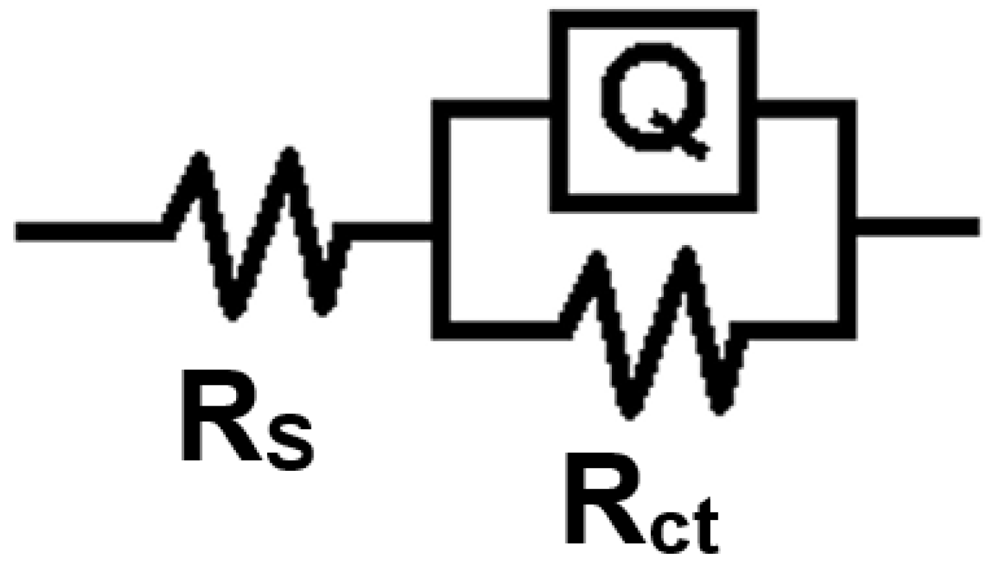
3.4.2. Electrochemical Impedance Spectroscopy (EIS) Studies
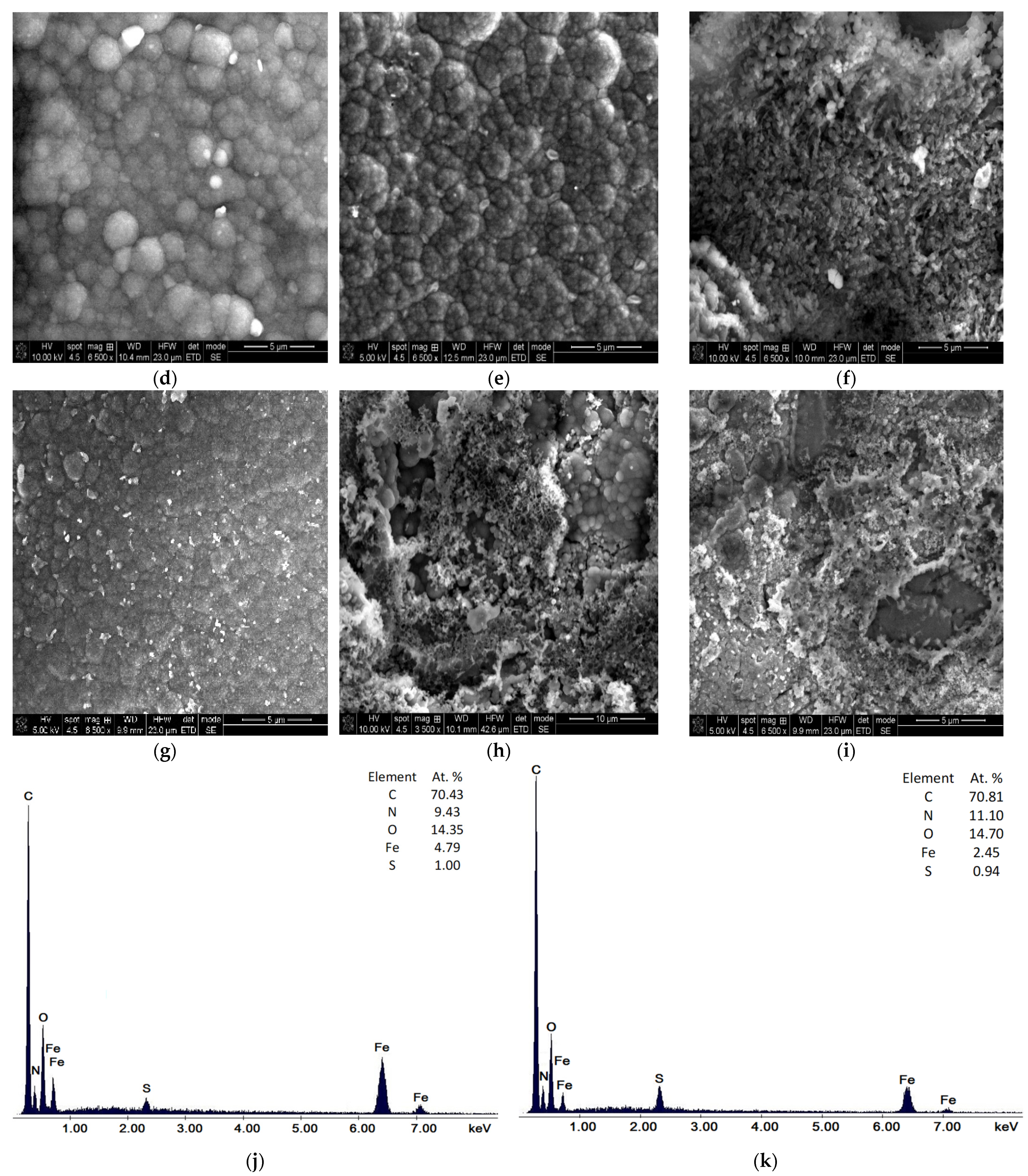
The protective effect of PNMPY-TW20/P3MT coated over OLC 45 in acid solution was examined by electrochemical impedance spectroscopy (EIS). Impedance experiments have been executed at open circuit potential to the frequency range from 100,000 Hz to 0.04 Hz with an AC wave of ±10 mV (peak-to-peak), and the impedance measurements have been performed at a rate of 10 points per decade amended in frequency. The EIS results supply knowledge regarding evaluating the anticorrosive features of the novel composite polymer as a protecting layer on OLC 45 corrosion. Figure 8a–f illustrates the Nyquist impedance diagrams obtained for the PNMPY-TW20/P3MT coatings of the OLC 45 sample and for an uncoated sample in sulfuric acid medium. As indicated by the Nyquist plots (Figure 8), the OLC 45 electrode presented a small capacitive loop, denoting that the charge transfer reaction has been prevailing throughout the entire corrosion process. From Figure 8a–f, it can be distinguished that the Nyquist plots for PNMPY-TW20/P3MT coated on OLC 45 electrode designate just one semicircle, which is characteristic of a charge transfer procedure. Figure 8a–f shows that the diameters of the capacitance loops by the coatings are higher than those uncovered and the measures of these loops increase upon perfecting the coatings, suggesting that these novel composite coatings possess superior defense features regarding the OLC 45 electrode in 0.5 M H2SO4 solution. It is obvious on the Nyquist diagrams that the impedance reaction of OLC 45 has been remarkably enhanced by the electrodeposition of the coatings, which implies that the obtaining protective layer was demonstrated by the attending of the PNMPY-TW20/P3MTcomposite. As well, these capacitive loops are not definite semicircles, and this occurrence is assigned to frequency dispersion, especially ascribed to roughness and inhomogeneities of the metal area [16,17,18,19,20,21,22,40,41,42,43,44,45]. Figure 8 displays that the diameters of the capacitance loops for coatings acquired at 5 mA/cm2 and at 3 mA/cm2 with 5:1, 3:5 and 1:1 molar ratios, at 1.2 V and 1.4 V with 5:1, 3:5 and 1:1 molar ratios (submitted time 20 and 30 min) are superior to these uncoated, supposing that they ensure a significant protective outcome for the OLC 45 sample in aggressive solution. It can be noticed in Figure 8 that the diameters of the capacitance loops of the PNMPY-TW20/P3MT coatings attained by galvanostatic and potentiostatic processes at 5 mA/cm2 and 3 mA/cm2 (with molar ratios of 5:1 and 3:5) are greater than those realized at 1.4 V potential applied, and, as a result, the inhibition efficiency of this coating is greater.
From the above analysis of Table 6, Table 7, Table 8 and Table 9 and plots of EIS 8–9, it was deduced that the PNMPY-TW20/P3MT coatings operated as an effective physical barrier that stopped the entrance of the corrosive ions into the coatings, lessening the charge transfer and, consequently, impeding the corrosion mechanism.
The Bode graphs of PNMPY-TW20/P3MT coating (Figure 9) divulged that the impedance modulus, at low frequencies, grows by the rising of the development of coatings, indicating that the electrodeposition of the inhibitive layer of composite enhances the corrosion protection of the studied OLC 45 in the H2SO4 solution. It is clear from Figure 9 that an uncoated electrode indicates a one-time constant proximate at a phase angle of 47° at medium and low frequencies; this displays an inductive comportment by diminished diffusive tendency. From Figure 9, it can be remarked that, in the attendance of composite coatings on the graph phase angle against the frequency logarithm, a maximum is indicated that is very well established at a phase angle estimated at 76°. Hence, in these circumstances, the coated samples have a greater capacitive behavior, in agreement with the Nyquist plots and experimental investigations acquired from potentiodynamic polarization data. An increase in Zmod indicates a superior protection capacity, and it is evident that Zmod increases when the coating improves. A higher Zmod leads to excellent protective effectiveness. The evaluation of the experimental data has been evidenced by fitting the results at the suitable equivalent circuit presented in Figure 10, and the various impedance characteristics, such as the solution resistance (Rs), the charge transfer resistance (Rct), the capacitance of a double layer (Cdl) and protection efficacy, were estimated and depicted in Table 6, Table 7, Table 8 and Table 9. Moreover, in the elaborated frequency interval, an equivalent circuit model has been suggested in order to fit and examine the attained EIS experiments. In this situation, the constant phase element, CPE, is exhibited in the circuit instead of a pure double layer capacitor (Cdl) to supply a more certain fit. The CPE is employed to represent the depression of the capacitance semicircle, which ascribes to the surface heterogeneity from the area roughness and impurities [16,17,18,19,20]. The impedance of CPE can be interpreted as: ZCPE = Y0−1(jω)−n, where ω is the angular frequency, j is the imaginary number (j2 = −1), Y0 is the amplitude suitable to a capacitance and n is the phase shift. The assessment of the n affords features regarding the stage of sample surface inhomogeneity [22,23,24,25,26]. The greater n value is connected to the decreased area roughness, i.e., minimized zone inhomogeneity. The CPE can represent resistance when n = 0, Y0 = R), capacitance when n = 1 (Y0 = C) and inductance when n = −1 (Y0 = 1/L) or Warburg impedance when n = 0.5 (Y0 = W), determined based on the evaluation of “n” [29,37,38,39,40,41,42,43,44,45]. Therefore, the inhibition effectiveness can be appraised utilizing the ensuing relationship: IE (%) = Rct − R0ct/Rct × 100, where Rct and R0ct are the charge transfer resistance values with and without the composite.
The EIS results indicate that the charge transfer resistance Rct elevated and the double layer capacitance Cdl lessened with composite coatings. As a result of increasing values of Rct with the PNMPY-TW20/P3MT coatings, the inhibition efficacy rose remarkably, which denotes that coating manifests valuable protection for the corrosion of the OLC 45 samples. The reduction in Cdl can be possible by a lower local dielectric constant and/or increase in the thickness of the electrical double layer, a consequence of the existence of composite actuated by adsorption to the interface of the electrode/environment. The coating electrodeposited onto the surface of the OLC 45 samples depicts a protecting layer onto the OLC 45 specimen. The Nyquist and Bode plots indicate that the action of corrosion was impeded by deposition of PNMPY-TW20/P3MT coatings, and this situation is effectuated as a diffusion barrier via a charge transfer procedure.

3.5. SEM Studies

Employing scanning electron microscopy (SEM), the morphology structure of the PNMPY-TW20/P3MT composite coatings attained over the OLC 45 substrate was examined. The SEM images of PNMPY-TW20/P3MT coatings’ electropolymerization in several circumstances on the OLC 45 sample are depicted in Figure 11. These images display a thick black film of the PNMPY-TW20/P3MT acquired by the galvanostatic and potentiostatic procedure, designating that the coated composite was realized.
Inspecting Figure 11a–e, it can be noticed that the PNMPY-TW20/P3MT coating has a uniform appearance of cauliflower configuration with a small globular-microstructure-assigned adherent, and compactness on the OLC 45 substrate was appreciated, which is suitable in the specialty literature [18,19,20,21,22,23,24,25,26,27,28,29,37,39,40,41,42,43,44,45,46]. The grains present dimensions of 5 μm, with a medium thickness of 40 μm. These micrographs exposed an eventual uniform layer to be attained onto the OLC 45 surface, and the characteristic of the coating is of such good quality that no crack on the coating is noticed. The dopant surfactant (Tween 20) integrated in the conducting polymers influences both the electropolymerization process and also the features of the obtained coating. The superior surface coating and greater adsorption action also explicated the best corrosion protection efficacy of the composite coatings. The EDS analysis of the PNMPY-TW20/P3MT-covered OLC 45 has been accomplished and the spectra were specified in Figure 11j,k. The attendant of the composite layer on the OLC 45 surface is observed from the peaks of C, N and S elements in the EDS spectrum. These outcomes agree with the FTIR spectrum of the composite coating, in which the Tw20 and oxalate ions exist in the polymer matrix.
Following immersion time from 0 and 120 h (168 h) in a 0.5 M H2SO4 environment, evident changes to the surface morphology of the coating have occurred according to the electrochemical measurements. The PNMPY-TW20/P3MT coatings realized by galvanostatic means (at 5 mA/cm2) displayed a non-damaging surveying after 120 h of immersion in the aggressive medium (Figure 11g), further verifying their excellent protection ability. This can be noticed in the micrographs: Figure 11h,i, which display the diffusion of aggressive SO42− ions in the coating substrate.

4. Conclusions

The PNMPY-TW20/P3MT composite coatings were successfully deposited homogeneously, compactly, uniformly and adherently on the OLC 45 sample and were achieved through employing the galvanostatic and potentiostatic procedure at different current densities and potentials in oxalic acid medium.
The electrochemical tests demonstrate that the PNMPY-TW20/P3MT comports as a protective film over OLC 45 in a 0.5 M H2SO4 environment.
The corrosion assessment of this PNMPY-TW20/P3MT-coated OLC 45 specimen is estimated to be ~10 times diminished compared to the uncoated OLC 45 sample, and the protection efficiency of this coating is more than 90%.
The examination of the FT-IR spectra establishes that the PNMPY-TW20/P3MT composite is constituted on the OLC 45 substrate.
The SEM micrographs of the PNMPY-TW20/P3MT coating on OLC 45 demonstrate a dense, homogeneous and strong adherent onto the OLC 45 surface, and the feature of the coating is of the greatest quality.
The electropolymerization method employed for acquiring the composite coating is the most suitable, relatively easy and inexpensive.
The corrosion protection comportment of the PNMPY-TW20/P3MT coating electrosynthesis under the optimum states has been investigated in 0.5 M H2SO4 medium by the potentiodynamic polarization and EIS processes.
The corrosion inhibition features follow the succession: PNMPY-TW20/P3MT to 5 mA/cm2 > 3 mA/cm2 > 1.2 V > 1.4 V for the reason that the attendance of these coatings establishes a considerable lessening in the corrosion process.
The superior surface coating and greater adsorption action also accounted for the best corrosion protection efficacy of the composite coatings.
Owing to the improved physical barrier result, the coating surface is dense, homogeneous, with a small porosity and higher protection capability, and the PNMPY-TW20/P3MT composite coatings have been more corrosion-resistant.
The PNMPY-TW20/P3MT coatings realized by the galvanostatic method (at 5 mA/cm2 and 3 mA/cm2) exhibited a non-damaging surveying after 96 h of immersion in the aggressive medium, further verifying their excellent protection capacity.
The PNMPY-TW20/P3MT coatings acquired at 5 mA/cm2 current density, molar ratio of 5:1 and 3:5 MPY-TW20:3MT at 20 min and 30 min, as well as 3 mA/cm2 current density, molar ratio of 5:1 and 3:5 MPY-TW20:3MT at 20 and 30 min enabled the best polymer-manifested anticorrosion protection yield compared to coating obtained at 1.4 V potential applied in the same conditions.
It is obvious that the composite coatings obstruct the offensiveness of the corrosive agent (H2SO4) to the OLC 45 substrate, and the novel composite PNMPY-TW20/P3MT attained by these means is encouraging and might extend to industrial applications for the protection of metals’ and their alloys’ surfaces against the corrosion process.

Author Contributions

Conceptualization, F.B.; methodology, F.B.; software, F.B. and M.A.M.; validation, F.B. and M.A.M.; formal analysis, F.B., S.P. and M.A.M., investigation, F.B. and S.P.; resources, F.B.; data curation F.B. and M.A.M.; writing—original draft preparation, F.B. and M.A.M.; writing—review and editing, F.B. and M.A.M.; visualization, F.B. and M.A.M.; supervision, F.B.; project administration, F.B. and M.A.M., funding acquisition, F.B. All authors have read and agreed to the published version of the manuscript.

Funding

This research received no external funding.

Institutional Review Board Statement

Not applicable.

Informed Consent Statement

Not applicable.

Data Availability Statement

Data is contained within the article.

Conflicts of Interest

The authors declare no conflict of interest.

References

  1. Abdel Hamid, Z.; Hasan Gomaa, M.; Abdel Rehim, S.S.; Abdel Hamid, M.; Ibrahim, A. Synthesis and Characterization of 400 Nanostructured Polyaniline Thin Films with Super hydrophobic Properties. Coatings 2019, 9, 748. [Google Scholar] [CrossRef] [Green Version]
  2. Zhai, Y.; Pan, K.; Zhang, E. Anti-Corrosive Coating of Carbon-Steel Assisted by Polymer-Camphor sulfonic Acid Embedded within Graphene. Coatings 2020, 10, 879. [Google Scholar] [CrossRef]
  3. Guptad, D.K.; Neupane, S.; Singh, S.; Karki, N.; Yadav, A.P. The effect of electrolytes on the coating of polyaniline on mild steel by electrochemical methods and its corrosion behavior. Prog. Org. Coat. 2021, 152, 106127. [Google Scholar] [CrossRef]
  4. Branzoi, F.; Branzoi, V. Enzymatic electrode obtained by immobilizing of urease into a nanocomposite film based on conducting polymers and different additives. Int. J. Polym. Mater. Polym. Biomater. 2014, 63, 549–556. [Google Scholar] [CrossRef]
  5. Silva, R.S.; Meneguzzi, Á. Passivation of Carbon Steel Using Intelligent Epoxy Paint. Coatings 2020, 10, 452. [Google Scholar] [CrossRef]
  6. Pruna, A.; Brânzoi, F. Electrochemical activity and microscopy of electrosynthesised poly (o-phenylenediamine) nanotubes. J. Polym. Res. 2012, 19, 9879. [Google Scholar] [CrossRef]
  7. Gallegos-Melgar, A.; Serna, S.A.; Lázaro, I.; Gutiérrez-Castañeda, E.-J.; Mercado-Lemus, V.H.; Arcos-Gutierrez, H.; Hernández-Hernández, M.; Porcayo-Calderón, J.; Mayen, J.; Monroy, M.D.A. Potentiodynamic Polarization Performance of a Novel Composite Coating System of Al2O3/Chitosan-Sodium Alginate, Applied on an Aluminum AA6063 Alloy for Protection in a Chloride Ions Environment. Coatings 2020, 10, 45. [Google Scholar] [CrossRef] [Green Version]
  8. Tavandashti, N.P.; Almas, S.M.; Esmaeilzadeh, E. Corrosion protection performance of epoxy coating containing alumina/PANI nanoparticles doped with cerium nitrate inhibitor on Al-2024 substrates. Prog. Org. Coat. 2021, 152, 106133. [Google Scholar] [CrossRef]
  9. Liu, A.; Tian, H.; Li, S.; Ju, X.; Yang, H.; Sun, Y.; Wang, L.; Li, W. Bioinspired layered hybrid coatings with greatly enhanced barrier effect and active corrosion protection performance. Prog. Org. Coat. 2021, 152, 106131. [Google Scholar] [CrossRef]
  10. Branzoi, F.; Băran, A.; Petrescu, S. Evaluation of Corrosion Protection Performance of New Polymer Composite Coatings on Carbon Steel in Acid Medium by Electrodeposition Methods. Coatings 2021, 11, 903. [Google Scholar] [CrossRef]
  11. Ji, S.; Gui, H.; Guan, G.; Zhou, M.; Guo, Q.; Tan, M.Y.J. Molecular design and copolymerization to enhance the anti-corrosion performance of waterborne acrylic coatings. Prog. Org. Coat. 2021, 153, 106140. [Google Scholar] [CrossRef]
  12. Branzoi, F.; Băran, A. The inhibition effect of some organic compounds on corrosion of brass and carbon steel in aggressive medium. Int. J. Electrochem. Sci. 2019, 14, 2780–2803. [Google Scholar] [CrossRef]
  13. Pekmez, N.O.; Abaci, E.; Cinkilli, K.; Yagan, A. Polybithiophene and its bilayers with polyaniline coatings on stainless steel by electropolymerization in aqueous medium. Prog. Org. Coat. 2009, 65, 462–468. [Google Scholar] [CrossRef]
  14. Branzoi, F.; Branzoi, V. Investigation of Protective Effect of Polymeric Film Coatings on Carbon Steel in Aggressive Solutions. Int. J. Electrochem. Sci. 2016, 11, 6564–6579. [Google Scholar] [CrossRef]
  15. Yagan, A.; Pekmez, N.Ö.; Yıldız, A. Poly (N-methylaniline) coatings on stainless steel by electropolymerization. Corros. Sci. 2007, 49, 2905–2919. [Google Scholar] [CrossRef]
  16. Zeybek, B.; Aksun, E. Electrodeposition of poly(N-methylpyrrole) on stainless steel in the presence of sodium dodecylsulfate and its corrosion performance. Prog. Org. Coat. 2015, 81, 1–10. [Google Scholar] [CrossRef]
  17. Pekmeza, N.Ö.; Cinkillia, K.; Zeybekba, B. The electrochemical copolymerization of pyrrole and bithiophene on stainless steel in the presence of SDS in aqueous medium and its anticorrosive performance. Prog. Org. Coat. 2014, 77, 1277–1287. [Google Scholar] [CrossRef]
  18. Redondo, M.I.; de la Blanca, E.S.; García, M.V.; González-Tejera, M.J. Poly(N-methylpyrrole) Electrodeposited on copper: Corrosion protection properties. Prog. Org. Coat. 2009, 65, 386–391. [Google Scholar] [CrossRef]
  19. Su, W.; Iroh, J.O. Electrodeposition mechanism, adhesion and corrosion performance of polypyrrole and poly (N-methylpyrrole) coatings on steel substrates. Synth. Met. 2000, 114, 225–234. [Google Scholar] [CrossRef]
  20. Çakmakci, I.; Duran, B.; Duran, M.; Bereket, G. Experimental and theoretical studies on protective properties of poly (pyrrole-co-n-methyl pyrrole) coatings on copper in chloride media. Corros. Sci. 2013, 69, 252–261. [Google Scholar] [CrossRef]
  21. Ren, S.; Barkey, D. Electrochemically Prepared Poly (3-methylthiophene) Films for Passivation of 430 Stainless Steel. J. Electrochem. Soc. 1992, 139, 1021. [Google Scholar] [CrossRef]
  22. Duran, B.; Bereket, G. Cyclic Voltammetric Synthesis of Poly(N-methyl pyrrole) on Copper and Effects of Polymerization Parameters on Corrosion Performance. Ind. Eng. Chem. Res. 2012, 51, 5246–5255. [Google Scholar] [CrossRef]
  23. Rui, M.; Zhu, A. The synthesis and corrosion protection mechanisms of PANI/CNT nanocomposite doped with organic phosphoric acid. Prog. Org. Coat. 2021, 153, 106134. [Google Scholar] [CrossRef]
  24. Martí, M.; Armelin, E.; Iribarren, J.I.; Alemán, C. Soluble polythiophenes as anticorrosive additives for marine epoxy paints. Mater. Corros. 2015, 66, 23–30. [Google Scholar]
  25. Gopi, D.; Saraswathy, R.; Kavitha, L.; Kim, D.-K. Electrochemical synthesis of poly(indole-co-thiophene) on low-nickel stainless steel and its anticorrosive performance in 0.5 mol L−1H2SO4. Polym. Int. 2013, 63, 280–289. [Google Scholar] [CrossRef]
  26. Sazou, D.; Kourouzidou, M.; Pavlidou, E. Potentiodynamic and potentiostatic deposition of polyaniline on stainless steel: Electrochemical and structural studies for a potential application to corrosion control. Electrochim. Acta 2007, 52, 4385–4397. [Google Scholar] [CrossRef]
  27. Branzoi, F.; Brânzoi, V.; Musina, A. Fabrication and characterisation of conducting composite films based on conducting polymers and functionalised carbon nanotubes. Surf. Interface Anal. 2012, 44, 1076–1081. [Google Scholar] [CrossRef]
  28. Zhou, W.; Wu, K.; Zhang, K.; Wang, Z.; Liu, Z.; Hu, S.; Fang, Y.; He, C. Studies on Corrosion Behaviors of Q235 Steel Coated by the Polypyrrole Films Doped with different dopants. Int. J. Electrochem. Sci. 2020, 15, 2594–2603. [Google Scholar] [CrossRef]
  29. Branzoi, F.; Branzoi, V.; Musina, A. Coatings based on conducting polymers and functionalized carbon nanotubes obtained by electropolymerization. Prog. Org. Coat. 2013, 76, 632–638. [Google Scholar] [CrossRef]
  30. Fuseini, M.; Zaghloul, M.M.Y. Statistical and qualitative analyses of the kinetic models using electrophoretic deposition of polyaniline. J. Ind. Eng. Chem. 2022. [Google Scholar] [CrossRef]
  31. Zaghloul, M.Y.; Zaghloul, M.M.Y.; Zaghloul, M.M.Y. Influence of Stress Level and Fibre Volume Fraction on Fatigue Performance of Glass Fibre-Reinforced Polyester Composites. Polymers 2022, 14, 2662. [Google Scholar] [CrossRef]
  32. Fuseini, M.; Zaghloul, M.M.Y.; Elkady, M.F.; El-Shazly, A.H. Evaluation of synthesized polyaniline nanofibres as corrosion protection film coating on copper substrate by electrophoretic deposition. J. Mater. Sci. 2022, 57, 6085–6101. [Google Scholar] [CrossRef]
  33. Zhang, J.; Zhu, A. Study on the synthesis of PANI/CNT nanocomposite and its anticorrosion mechanism in waterborne Coatings. Prog. Org. Coat. 2021, 159, 106447. [Google Scholar] [CrossRef]
  34. Pan, Y.; Pu, D.L.; Li, Y.Q.; Zheng, Q.H. Origin of the antioxidation mechanism of RuAl(1 1 0) surface from first-principles calculations. Mater. Sci. Eng. B 2020, 259, 114580. [Google Scholar] [CrossRef]
  35. Pan, Y.; Wen, M. Insight into the oxidation mechanism of Nb3Si(111) surface: First-principles calculations. Mater. Res. Bull. 2018, 107, 484–491. [Google Scholar] [CrossRef]
  36. Pan, Y.; Pu, D.; Jia, Y. Adjusting the correlation between the oxidation resistance and mechanical properties of Pt-based thermal barrier coating. Vacuum 2020, 172, 109067. [Google Scholar] [CrossRef]
  37. Branzoi, F.; Băran, A.; Ludmila, A.; Alexandrescu, E. The inhibition action of some organic polymers on the corrosion carbon steel in acidic media. Chem. Pap. 2020, 74, 4315–4335. [Google Scholar] [CrossRef]
  38. Menkuer, M.; Ozkazanc, H. Anticorrosive polypyrrole/zirconium-oxide composite film prepared in oxalic acid and dodecylbenzene sulfonic acid mix electrolyte. Prog. Org. Coat. 2020, 147, 105815. [Google Scholar] [CrossRef]
  39. Branzoi, F.; Branzoi, V. Investigation of some nonionic surfactants as corrosion inhibitors for carbon steel in sulfuric acid medium. Int. J. Electrochem. Sci. 2017, 12, 7638–7658. [Google Scholar] [CrossRef]
  40. Zeybek, B.; Pekmez, N.O.; Kilic, E. Electrochemical synthesis of bilayer coatings of poly(N-methylaniline) and polypyrrole on mild steel and their corrosion protection performances. Electrochim. Acta 2011, 56, 9277–9286. [Google Scholar] [CrossRef]
  41. González, M.B.; Saidman, S.B. Electrodeposition of polypyrrole on 316L stainless steel for corrosion prevention. Corros. Sci. 2011, 53, 276–282. [Google Scholar] [CrossRef]
  42. Herrasti, P.; Patil, P. Corrosion protective poly (o-ethoxyaniline) coatings on copper. Electrochim. Acta 2007, 53, 927–933. [Google Scholar]
  43. Duran, B.; Turhan, M.C.; Bereket, G.; Sarac, A.S. Electropolymerization, characterization and corrosion performance of poly(N-ethylaniline) on copper. Electrochim. Acta 2009, 55, 104–112. [Google Scholar] [CrossRef]
  44. Yagan, A.; Pekmez, O.N.; Yildiz, A. Poly(N-ethylaniline) coatings on 304 stainless steel for corrosion protection in aqueous HCl and NaCl solutions. Electrochim. Acta 2008, 53, 2474–2482. [Google Scholar] [CrossRef]
  45. Shi, S.; Zhao, Y.; Zhang, Z.; Yu, L. Corrosion protection of a novel SiO2/PANI coating for Q235 carbon steel. Prog. Org. Coat. 2019, 132, 227–234. [Google Scholar] [CrossRef]
  46. Yagan, A.; Pekmez, O.N.; Yildiz, A. Electrodeposition of poly (N-methyl aniline) on mild steel: Synthesis, Characterization and corrosion protection. J. Electroanal. Chem. 2005, 578, 231–238. [Google Scholar] [CrossRef]
Scheme 1. Schematic diagram of the electrodeposition process (Ref. = SCE reference electrode, WE = OLC 45 working electrode, CE = platinum sheet counter electrode).
Coatings 12 01062 sch001
Scheme 2. Film coating adhesion assessment by “standard sellotape test”.
Coatings 12 01062 sch002
Figure 1. Galvanostatic deposition of PNMPY-TW20/P3MT/OLC 45 at current densities (a) 3 mA/cm2 and (b) at 5 mA/cm2 for 1200 s and 1800 s to different molar ratio for PNMPY-TW20 and P3MT.
Coatings 12 01062 g001
Figure 2. Potentiostatic depositions of PNMPY-TW20/P3MT OLC 45 at potential 1.2 V (a) and 1.4 V (b) vs. SCE for 1200-1800 s with different molar ratio for PNMPY-TW20 and P3MT.
Coatings 12 01062 g002
Figure 3. Cyclic voltammograms of OLC 45 electrode coated with PNMPY-TW20/P3MT in 0.3 M H2C2O4 solution monomer free at potential interval −0.5 and 1.5 V vs. SCE and scan rate of 20 mV/s.
Coatings 12 01062 g003
Figure 4. FT-IR spectra of (a) NMPY, (b) 3MT and (c,d) PMPY-Tw20/P3MT/OLC 45 electrodeposition onto OLC 45 sample with galvanostatic and potentiostatic method (c) 5 mA/cm2, (d) 1.2 V with 5:1 molar ratio for MPY-TW20:3MT and permitted for 20 min.
Coatings 12 01062 g004
Figure 5. Polarization curves of PNMPY-TW20/P3MT coated and uncoated on OLC 45 electrode in 0.5 M H2SO4 by galvanostatic proceeding at (a) 3 mA/cm2 and (b) 5 mA/cm2 current density to various molar ratio, and the electrodeposition has been permitted for 20 and 30 min.
Coatings 12 01062 g005
Figure 6. Polarization curves of PNMPY-TW20/P3MT coated and uncoated on OLC 45 electrode in 0.5 M H2SO4 by potentiostatic procedure at 1.2 V (a) and 1.4 V (b) potential applied at differing molar ratio, and the electrodeposition has been admitted for 20 and 30 min.
Coatings 12 01062 g006
Figure 7. Polarization curves of PNMPY-TW20/P3MT coated and uncoated OLC 45 sample in 0.5 M H2SO4 by electrochemical polymerization at (a) 5 mA/cm2, (b) 3 mA/cm2 current density and 1.2 V (c) potential with differing molar ratio at varied immersion times.
Coatings 12 01062 g007aCoatings 12 01062 g007b
Figure 8. Nyquist graphs for uncoated and PNMPY-TW20/P3MT-coated OLC 45 sample by galvanostatic, at (a) 3 mA/cm2 and (b) 5 mA/cm2 current density, and potentiostatic, at 1.2 V (c) and 1.4 V (d) potential, procedures with diverse molar ratio for PNMPY-TW20 and P3MT.
Coatings 12 01062 g008aCoatings 12 01062 g008b
Figure 9. Bode diagrams for uncoated and PNMPY-TW20/P3MT-coated OLC 45 sample by galvanostatic, at (a,b) 3 mA/cm2 and (c,d) 5 mA/cm2 current density, and potentiostatic, at 1.2 V (e,f) and 1.4 V (g,h) potential, procedures with diverse molar ratio for PNMPY-TW20 and P3MT.
Coatings 12 01062 g009aCoatings 12 01062 g009b
Figure 10. Equivalent circuit.
Coatings 12 01062 g010
Figure 11. SEM micrographs of OLC 45 electrode coated with PNMPY-TW20/P3MT/OLC 45, (a,b) at 3 mA/cm2, (c,d) 5 mA/cm2 with 5:1, 3:5 molar ratio, (e) 1.2 V and (f) 1.4V and (gi) after 96 h, 120 h and 168 h immersion time in 0.5 M H2SO4, (j,k) the EDS spectra of PNMPY-TW20/P3MT/OLC 45.
Coatings 12 01062 g011aCoatings 12 01062 g011b
Table 1. Kinetic corrosion parameters of coated and uncoated OLC 45 sample in 0.5 M H2SO4 solution at 25 °C.
PNMPY-TW20/P3MT/OLC 45 + H2SO4E
(mV)
icorr
(mA/cm2)
Rp
(Ωcm2)
ba
(mV/Decade)
bc
(mV/Decade)
E%RmpyPm/year%P
OLC 45 uncoated−4960.8871794−93-41311-
PNMPY-TW20/P3MT
i = 3 mA 1:1 t = 20 min
−4030.04428640−1039420.530.520.0055
PNMPY-TW20/P3MT
i = 3 mA 3:5
−4100.03335560−849615.40.390.0054
PNMPY-TW20/P3MT
i = 3 mA 5:1
−4160.041534368−889519.460.490.0052
PNMPY-TW20/P3MT
i =3 mA 1:1 t = 30 min
−4130.04530660−9294210.530.0066
PNMPY-TW20/P3MT
i = 3 mA 3:5
−4030.05124548−10295200.50.0066
PNMPY-TW20/P3MT
i = 3 mA 5:1
−4140.03139260−7896140.360.0046
Table 2. Kinetic corrosion parameters of coated and uncoated OLC 45 sample in 0.5 M H2SO4 solution at 25 °C.
PNMPY-TW20/P3MT/OLC 45 + H2SO4E
(mV)
icorr
(mA/cm2)
Rp
(Ωcm2)
ba
(mV/Decade)
bc
(mV/Decade)
E%RmpyPmm/year%P
OLC 45 uncoated−4960.8871794−93-41311-
PNMPY-TW20/P3MT
i = 5 mA 1:1 t = 20 min
−4280.05619069−689426.130.660.016
PNMPY-TW20/P3MT
i = 5 mA 3:5
−4260.03832178−7995.617.730.450.0076
PNMPY-TW20/P3MT
i = 5 mA 5:1
−4100.04123356−929521.460.540.0078
PNMPY-TW20/P3MT
i = 5 mA 1:1 t = 30 min
−4670.04529569−809520.760.5270.027
PNMPY-TW20/P3MT
i = 5 mA 3:5
−4020.03934961−6795.618.660.4730.0046
PNMPY-TW20/P3MT
i = 5 mA 5:1
−4050.02751756−999712.60.3190.0034
Table 3. Kinetic corrosion parameters of coated and uncoated OLC 45 sample in 0.5 M H2SO4 solution at 25 °C.
PNMPY-TW20/P3MT/OLC 45 + H2SO4E
(mV)
icorr
(mA/cm2)
Rp
(Ωcm2)
ba
(mV/Decade)
bc
(mV/Decade)
E%RmpyPmm/year%P
OLC 45 uncoated−4960.8871794−93-41311-
PNMPY-TW20/P3MT
E = 1.2 V 1:1 t = 20 min
−4370.07419177−869134.530.8670.017
PNMPY-TW20/P3MT
E = 1.2 V 3:5
−4400.05724073−979426.60.670.015
PNMPY-TW20/P3MT
E = 1.2 V 5:1
−4280.061217871049328.460.720.012
PNMPY-TW20/P3MT
E = 1.2 V 1:1 t = 30 min
−4530.05526287−959425.120.630.018
PNMPY-TW20/P3MT
E = 1.2 V 3:5
−4260.04133860−779519.130.480.007
PNMPY-TW20/P3MT
E = 1.2 V 5:1
−4100.03635859909610.730.2720.0052
Table 4. Kinetic corrosion parameters of coated and uncoated OLC 45 sample in 0.5 M H2SO4 solution at 25 °C.
PNMPY-TW20/P3MT/OLC 45 + H2SO4E
(mV)
icorr
(mA/cm2)
Rp
(Ωcm2)
ba
(mV/Decade)
bc
(mV/Decade)
E%RmpyPmm/year%P
OLC 45 uncoated−4960.8871794−93-41311-
PNMPY-TW20/P3MT
E = 1.4 V 1:1 t = 20 min
−4260.05122253−9194240.510.0114
PNMPY-TW20/P3MT
E = 1.4 V 3:5
−4050.04628567−639421.40.5440.006
PNMPY-TW20/P3MT
E = 1.4 V 5:1
−4100.03237150−9396150.380.0052
PNMPY-TW20/P3MT
E = 1.4 V 1:1 t = 30 min
−4050.06716956−949231.260.790.0096
PNMPY-TW20/P3MT
E = 1.4 V 3:5
−4100.05619660−8493260.660.0091
PNMPY-TW20/P3MT
E = 1.4 V 5:1
−4120.04422850−749520.50.5210.0084
Table 5. Kinetic corrosion parameters of coated and uncoated OLC 45 sample in 0.5 M H2SO4 solution at 25 °C at varied immersion times.
PNMPY-TW20/P3MT/OLC 45 + H2SO4E
(mV)
icorr
(mA/cm2)
Rp
(Ωcm2)
ba
(mV/Decade)
bc
(mV/Decade)
RmpyPmm/yearE%
i = 5 mA/cm2 3:5
t = 30 min 0 h
−4020.03933461−6718.60.4795
i = 5 mA/cm2 3:5
t = 30 min 24 h
−4350.051310120−69240. 6194
i = 5 mA/cm2 3:5
t = 30 min 48 h
−4430.058296134−70270. 6893
i = 5 mA/cm2 3:5
t = 30 min 72 h
−4410.057302129−71260. 6794
i = 5 mA/cm2 3:5
t = 30 min 96 h
−4320.049398125−68220. 5894
i = 5 mA/cm2 3:5
t = 30 min 120 h
−4370.059300137−69270. 6993
i = 5 mA/cm2 3:5
t = 30 min 144 h
−4360.063278132−67290. 7493
i = 5 mA/cm2 3:5
t = 30 min 168 h
−4300.073270133−68340. 8692
i = 3 mA/cm2 5:1
t = 20 min 0 h
−4030.04428646−9220.50.5295
i = 3 mA/cm2 5:1
t = 20 min 24 h
−4130.07210677−57330.8592
i = 3 mA/cm2 5:1
t = 20 min 48 h
−4140.11799130−68541.3587
i = 3 mA/cm2 5:1
t = 20 min 96 h
−4270.1887131−67812.1180
i = 3 mA/cm2 5:1
t = 20 min 120 h
−4310.1981133−69862.1880
E = 1.2 V 1:1
t = 30 min 0 h
−4530.05526287−9525.120.6394
E = 1.2 V 1:1
t = 30 min 24 h
−5250.11150112−10051.31.3088
E = 1.2 V 1:1
t = 30 min 48 h
−5400.16144105−9374.61.8982
E = 1.2 V 1:1
t = 30 min 96 h
−5010.3271103−981483.7565
E = 1.2 V 1:1
t = 30 min 120 h
−4820.4669110−781493.7950
Table 6. EIS parameters of uncoated and coated by PNMPY-TW20/P3MT of OLC 45 sample in 0.5 M H2SO4 medium at 25 °C.
The System
PNMPY-TW20/P3MT/OLC 45 + H2SO4
Rs
(ohm × cm2)
Q−Yo
S⋅s-n⋅cm−2
Q−nRct
(ohm × cm2)
χ2E%
OLC 45 uncoated0.8810.00670.773134.764 × 10−3
PNMPY-TW20/P3MT i = 3 mA/cm2 1:1 t = 20 min1.030.002020.733854.514 × 10−385
PNMPY-TW20/P3MT i = 3 mA/cm2 3:51.5350.000370.8521192.500 × 10−390
PNMPY-TW20/P3MT i = 3 mA/cm2 5:12.4610.0010930.7911592.543 × 10−392
PNMPY-TW20/P3MT i = 3 mA/cm2 1:1 t = 30 min1.8420.0033590.6191464.321 × 10−391
PNMPY-TW20/P3MT i = 3 mA/cm2 3:51.5760.0010330.8101624.986 × 10−393
PNMPY-TW20/P3MT i = 3 mA/cm2 5:11.5120.0011050.8152055.590 × 10−394
Table 7. EIS parameters of uncoated and coated by PNMPY-TW20/P3MTof OLC 45 sample in 0.5 M H2SO4 medium at 25 °C.
The System
PNMPY-TW20/P3MT/OLC 45 + H2SO4
Rs
(ohm × cm2)
Q−Yo
S⋅s-n⋅cm−2
Q−nRct
(ohm × cm2)
χ2E%
OLC 45 uncoated0.8810.00670.773134.764 × 10−3
PNMPY-TW20/P3MT i = 5 mA/cm2 1:1 t = 20 min2.1260.001140.8454872.279 × 10−386
PNMPY-TW20/P3MT i = 5 mA/cm2 3:51.5430.000780.8281522.372 × 10−392
PNMPY-TW20/P3MT i = 5 mA/cm2 5:11.3220.0009100.8311232.752 × 10−390
PNMPY-TW20/P3MT i = 5 mA/cm2 1:1 t = 30 min0.7440.002620.8512945.937 × 10−387
PNMPY-TW20/P3MT i = 5 mA/cm2 3:52.6550.00024350.86621882.559 × 10−394
PNMPY-TW20/P3MT i = 5 mA/cm2 5:12.370.00062860.83362334.505 × 10−395
Table 8. EIS parameters of uncoated and coated by PNMPY-TW20/P3MTof OLC 45 sample in 0.5M H2SO4 medium at 25 °C.
PNMPY-TW20/P3MT/OLC 45 + H2SO4Rs
(ohm × cm2)
Q−Yo
S⋅s-n⋅cm−2
Q−nRct
(ohm × cm2)
χ2E%
OLC 45 uncoated0.8810.00670.773134.764 × 10−3
PNMPY-TW20/P3MT E = 1.2 V 1:1 t = 20 min3.7920.0017490.78031093.247 × 10−388
PNMPY-TW20/P3MT E = 1.2 V 3:53.5040.0002870.7931324.632 × 10−391
PNMPY-TW20/P3MT E = 1.2 V 5:11.3740.0010880.85481823.952 × 10−393
PNMPY-TW20/P3MTE = 1.2 V 1:1 t = 30 min1.7080.0014080.81171724.271 × 10−393
PNMPY-TW20/P3MT E = 1.2 V 3:51.8310.0017810.82282064.271 × 10−394
PNMPY-TW20/P3MT E = 1.2 V 5:17.6120.0004530.74262466.451 × 10−395
Table 9. EIS parameters of uncoated and coated by PNMPY-TW20/P3MTof OLC 45 sample in 0.5 M H2SO4 medium at 25 °C.
PNMPY-TW20/P3MT/OLC 45 + H2SO4Rs
(ohm × cm2)
Q−Yo
S⋅s-n⋅cm−2
Q−nRct
(ohm × cm2)
χ2E%
OLC 45 uncoated0.8810.00670.773134.764 × 10−3
PNMPY-TW20/P3MT E = 1.4 V 1:1 t = 20 min1.0840.0033380.7911856.073 × 10−385
PNMPY-TW20/P3MT E = 1.4 V 3:52.1470.0009660.8165903.865 × 10−386
PNMPY-TW20/P3MT E = 1.4 V 5:11.4970.0018130.81281233.370 × 10−390
PNMPY-TW20/P3MT E = 1.4 V 1:1 t = 30 min1.0570.0020980.8644814.558 × 10−384
PNMPY-TW20/P3MT E = 1.4 V 3:51.5580.0015510.829993.773 × 10−387
PNMPY-TW20/P3MT E = 1.4 V 5:13.5630.0008880.83391595.875 × 10−392
Publisher’s Note: MDPI stays neutral with regard to jurisdictional claims in published maps and institutional affiliations.

