
Utilization of Steel Slag in Road Semi-Rigid Base: A Review


Abstract
:1. Introduction
2. Materials
2.1. Physical Characteristics of SS

| Particle Size (mm) | ASG (g/cm3) | CV (%) | LA (%) | WA (%) | EFP (%) | References |
|---|---|---|---|---|---|---|
| 4.75–9.5 | - | 10.3 | 8.5 | - | 10.1 | [38] |
| ≥9.5 | - | 6.7 | ||||
| 0–4.75 | 3.37 | 23.5 | - | 1.33 | 0.0 | [39] |
| 4.75–16 | 3.48 | |||||
| 16–26.5 | 3.47 | |||||
| 0.06–50 | 3.34 | - | 20 | 0.85 | - | [16] |
| 0.075–31.5 | 3.31 | 16.7 | 21.5 | 0.43 | 5.7 | [40] |
| <1 | 3.35 | - | - | 0.40 | - | [41] |
| 0.075–31.5 | 3.50 | 16.3 | 12.05 | 2.00 | 1.1 | [42] |
| 0–25 | 2.90–3.20 | - | - | ≤1.50 | - | [43] |
| 5–10 | 3.25 | 13.6 | 13.2 | 2.70 | 5.1 (4.75–9.5mm) | [44] |
| 10–16 | 3.26 | 1.96 | 4.3 (>9.5mm) | |||
| 0.075–31.5 | 3.24–3.36 | 17.5 | 18.5 | 0.46 | 4.6 | [45] |
| 0.075–31.5 | 3.55 | 14.5 | 11.8 | 2.60 | 4.7 | [46] |
| 0–5 | - | - | - | - | - | [47] |
| 0–25 | - | 19.7 | - | - | - | [48] |
| 0.075–31.5 | - | 20.7 | - | - | - | [49] |
| 0–10 | 3.14 | - | - | 4.44 | - | [50] |
2.2. Chemical and Mineralogical Characteristics of SS
| CaO | Fe2O3+FeO | SiO2 | MgO | MnO | P2O5 | Al2O3 | SO3 | Na2O+K2O | f-CaO | References |
|---|---|---|---|---|---|---|---|---|---|---|
| 51.23 | 16.78 | 8.59 | 3.93 | 2.26 | 1.52 | 1.29 | 0.30 | - | 2.47 | [39] |
| - | 89.00 | 1.00 | - | - | - | - | - | - | - | [16] |
| 66.58 | 3.20 | 21.86 | 1.39 | - | - | 5.46 | 0.32 | 0.91 | - | [46] |
| 52.52 | 0.33 | 23.72 | 4.50 | 0.97 | - | 2.26 | 0.76 | - | - | [47] |
| 40–50 | 7–10 | 10–15 | 10.82 | - | 3–5 | - | - | - | 2.10 | [48] |
| 21.08 | 12.84 | 14.21 | 13.49 | - | - | 5.83 | - | - | - | [49] |
| 24.98 | 25.45 | 17.08 | 10.58 | 8.91 | - | 5.40 | 0.25 | 0.25 | - | [57] |
| 45.90 | 11.20 | 16.30 | 6.50 | - | 4.10 | 9.70 | - | - | - | [58] |
| 42.72 | 25.02 | 15.77 | 4.79 | 4.79 | 0.86 | 6.07 | - | 0.08 | 0.71 | [50] |
| 19.59 | 40.74 | 22.69 | 0.23 | 0.13 | 0.60 | 12.75 | - | - | <0.01 | [59] |
| 35.30 | 1.20 | 33.40 | 6.50 | 0.75 | - | 18.20 | - | - | - | [34] |
3. Performance Evaluation and of SS Mixtures
3.1. Cement Stabilized Steel Slag (CSS)
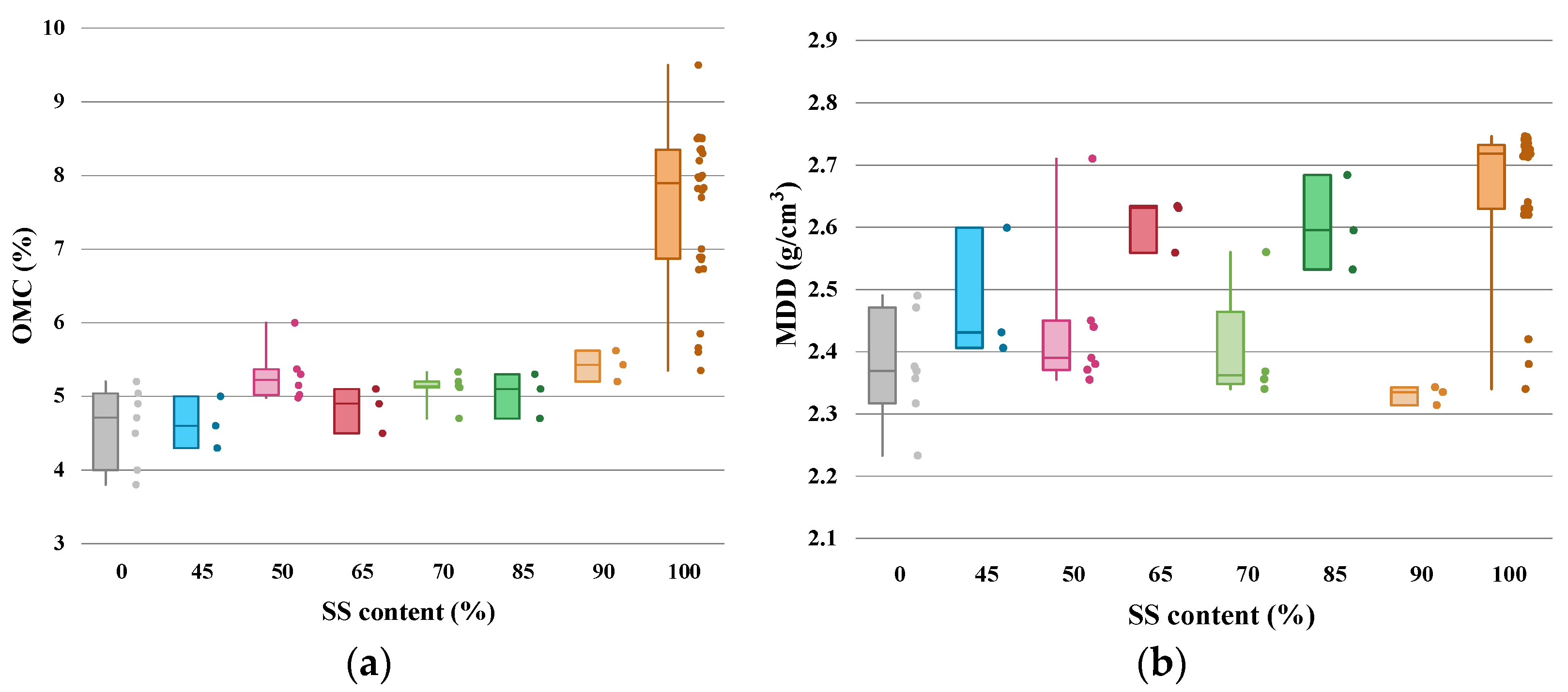
3.1.1. OMC and MDD of CSS
3.1.2. UCS of CSS
3.1.3. DS of CSS
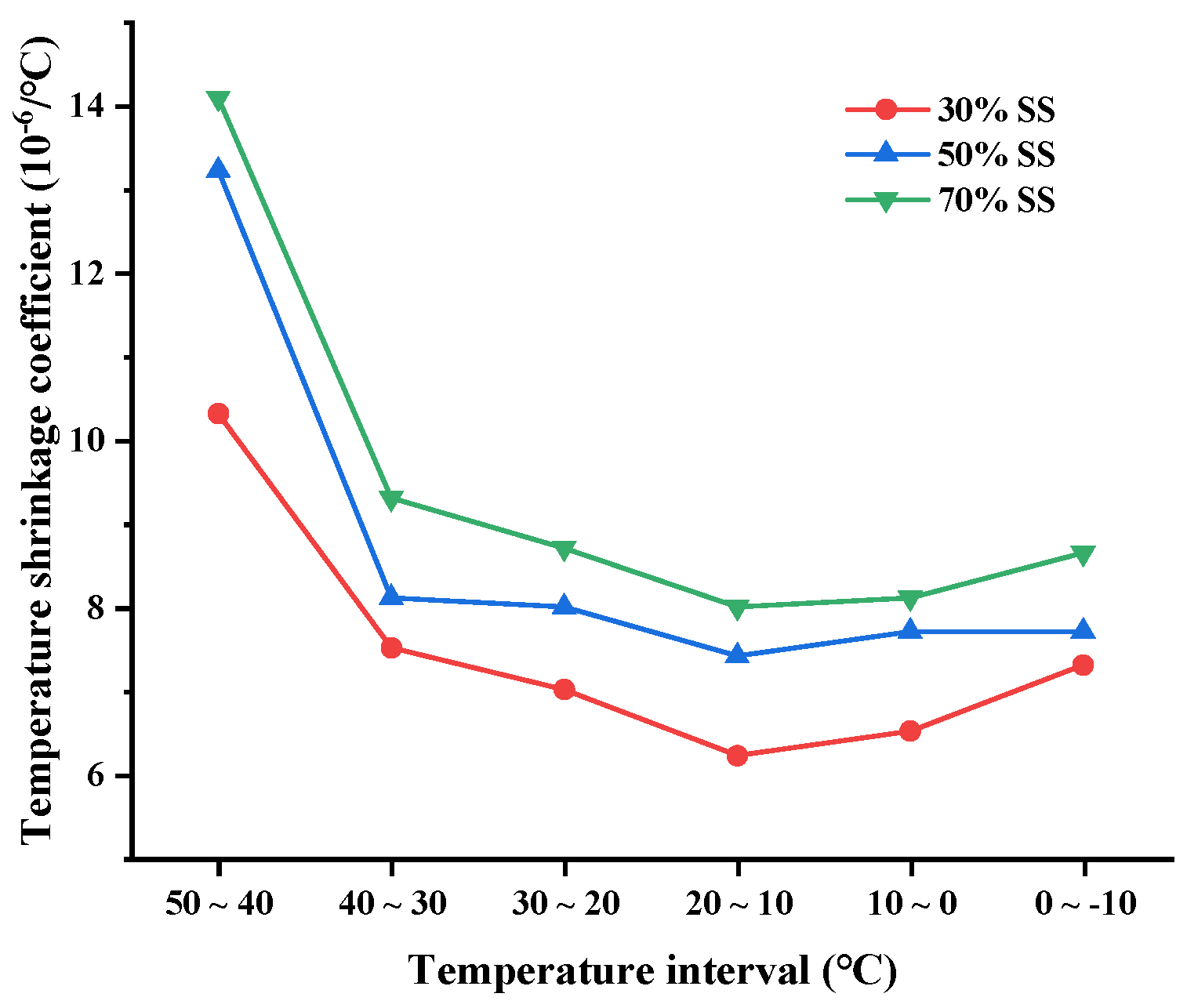
3.1.4. TS of CSS
3.2. Lime–Fly Ash Stabilized Steel Slag (LFSS)
| Lime: Fly Ash Content (%) | Binder: Aggregate Content (%) | OMC (%) | MDD (g/cm3) | References |
|---|---|---|---|---|
| 1:3 | 16:84 | 5.60–6.10 | 2.29–2.58 | [58] |
| 1:3 | 1:2.5, 1:3, 1:3.5, 1:4 | 8.10–10.60 | 2.07–2.28 | [59] |
| 6:19, 1:3, 4:11 | 25:75, 20:80, 15:85 | 8.7–14.0 | 1.69–2.00 | [74] |
| 1:3 | 25:75, 20:80, 15:85 | - | - | [75] |
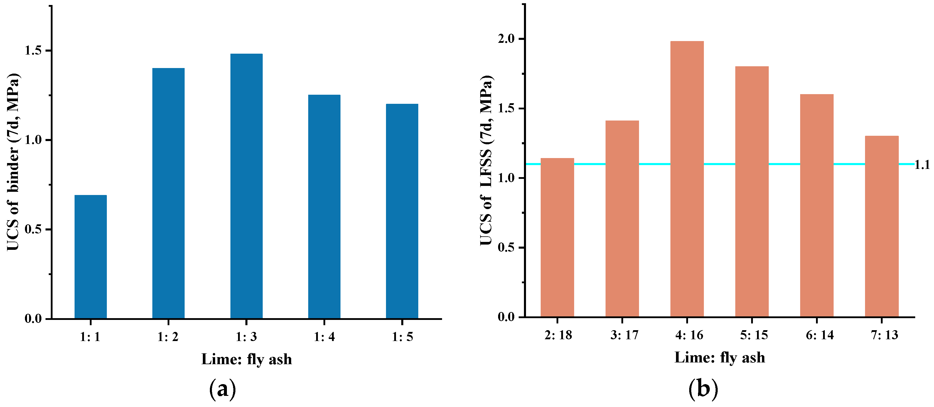
3.2.1. UCS of LFSS
3.2.2. DS of LFSS
3.2.3. TS of LFSS
3.3. Cement–Fly Ash Stabilized Steel Slag (CFSS)
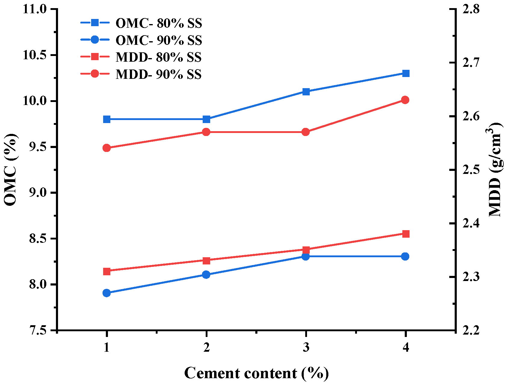
3.3.1. OMC and MDD of CFSS
3.3.2. UCS of CFSS
3.3.3. DS of CFSS
3.3.4. Inhibition Mechanism of Fly Ash on CFSS
4. Numerical Simulation
5. Environmental Impacts
6. Conclusions
Author Contributions
Funding
Institutional Review Board Statement
Informed Consent Statement
Data Availability Statement
Acknowledgments
Conflicts of Interest
Abbreviations
| ASG | Apparent specific gravity | LA | Los Angeles abrasion |
| CFSS | Cement–fly ash stabilized steel slag | LCA | Life cycle assessment |
| C-S-H | Calcium silicate hydrates | LFSS | Lime–fly ash stabilized steel slag |
| CSM | Cement stabilized macadam | MD | Molecular dynamics |
| CSS | Cement stabilized steel slag | MDD | Maximum dry density |
| CV | Crushing value | OMC | Optimum moisture content |
| DEM | Discrete element method | SS | Steel slag |
| DS | Drying shrinkage | TS | Temperature shrinkage |
| DSC | Drying shrinkage coefficient | TSC | Temperature shrinkage coefficient |
| EFP | Elongated and flaky particles | UCS | Unconfined compressive strength |
| FEM | Finite element method | WA | Water absorption |
References
- Li, B.; Tang, B.; Ma, Z.; Cheng, H.; Li, H. Physical and chemical properties of steel slag and utilization technology of steel slag at home and abroad. In Proceedings of the IOP Conference Series: Earth and Environmental Science, Moscow, Russia, 27 May–6 June 2019; p. 032012. [Google Scholar]
- Song, Q.; Guo, M.; Wang, L.; Ling, T. Use of steel slag as sustainable construction materials: A review of accelerated carbonation treatment. Resour. Conserv. Recycl. 2021, 173, 105740. [Google Scholar] [CrossRef]
- Gu, X.; Yu, B.; Dong, Q.; Deng, Y. Application of secondary steel slag in subgrade: Performance evaluation and enhancement. J. Clean. Prod. 2018, 181, 102–108. [Google Scholar] [CrossRef]
- Gençel, O.; Karadag, O.; Oren, O.H.; Bilir, T. Steel slag and its applications in cement and concrete technology: A review. Constr. Build. Mater. 2021, 283, 122783. [Google Scholar] [CrossRef]
- Hayashi, A.; Watanabe, T.; Kaneko, R.; Takano, A.; Takahashi, K.; Miyata, Y.; Matsuo, S.; Yamamoto, T.; Inoue, R.; Ariyama, T. Decrease of Sulfide in Enclosed Coastal Sea by Using Steelmaking Slag. Tetsu-to-Hagane 2012, 98, 207–214. [Google Scholar] [CrossRef] [Green Version]
- Wang, Z.; Sohn, I. A review on reclamation and reutilization of ironmaking and steelmaking slags. J. Sustain. Metall. 2019, 5, 127–140. [Google Scholar] [CrossRef]
- Gao, X.; Okubo, M.; Maruoka, N.; Shibata, H.; Ito, T.; Kitamura, S.-Y. Production and utilisation of iron and steelmaking slag in Japan and the application of steelmaking slag for the recovery of paddy fields damaged by Tsunami. Miner. Process. Extr. Metall. 2015, 124, 116–124. [Google Scholar] [CrossRef]
- Semykina, A.; Shatokha, V.; Seetharaman, S. Innovative approach to recovery of iron from steelmaking slags. Ironmak. Steelmak. 2010, 37, 536–540. [Google Scholar] [CrossRef]
- Wang, X.; Li, X.; Yan, X.; Tu, C.; Yu, Z. Environmental risks for application of iron and steel slags in soils in China: A review. Pedosphere 2021, 31, 28–42. [Google Scholar] [CrossRef]
- Yu, H.; Ma, T.; Wang, D.; Wang, C.; Lu, S.; Zhu, X. Review on China’s pavement engineering research·2020. China J. Highw. Transp. 2020, 33, 1–66. [Google Scholar]
- Guo, J.; Bao, Y.; Wang, M. Steel Slag in China: Treatment, Recycling, and Management. Waste Manag. 2018, 78, 318–330. [Google Scholar] [CrossRef]
- Yildirim, I.Z.; Prezzi, M. Chemical, Mineralogical, and Morphological Properties of Steel Slag. Adv. Civ. Eng. 2011, 2011, 463638. [Google Scholar] [CrossRef] [Green Version]
- Motz, H.; Geiseler, J. Products of steel slags an opportunity to save natural resources. Waste Manag. 2000, 21, 285–293. [Google Scholar] [CrossRef]
- Yi, H.; Xu, G.; Cheng, H.; Wang, J.; Wan, Y.; Chen, H. An overview of utilization of steel slag. Procedia Environ. Sci. 2012, 16, 791–801. [Google Scholar] [CrossRef] [Green Version]
- Riley, A.L.; MacDonald, J.M.; Burke, I.T.; Renforth, P.; Jarvis, A.P.; Hudson-Edwards, K.A.; McKie, J.; Mayes, W.M. Legacy iron and steel wastes in the UK: Extent, resource potential, and management futures. J. Geochem. Explor. 2020, 219, 106630. [Google Scholar] [CrossRef]
- Behiry, A.E.A.E.-M. Evaluation of steel slag and crushed limestone mixtures as subbase material in flexible pavement. Ain Shams Eng. J. 2013, 4, 43–53. [Google Scholar] [CrossRef] [Green Version]
- Kumar, P.; Kumar, A. Steel industry waste utilisation in road sector of India. J. Inst. Eng. (India) Civ. Eng. Div. 2000, 80, 182–185. [Google Scholar]
- Karatağ, H.; Fırat, S.; Işik, N.S. Assessment of performance of steel slag used in road base by finite element analysis. In Proceedings of the 13th International Congress on Advances in Civil Engineering, Izmir, Turkey, 12–14 September 2018. [Google Scholar]
- Pasetto, M.; Baldo, N. Mix design and performance analysis of asphalt concretes with electric arc furnace slag. Constr. Build. Mater. 2011, 25, 3458–3468. [Google Scholar] [CrossRef]
- Pasetto, M.; Baldo, N. Influence of the aggregate skeleton design method on the permanent deformation resistance of stone mastic asphalt. Mater. Res. Innov. 2014, 18, S3-96–S3-101. [Google Scholar] [CrossRef]
- Bessa, I.S.; Castelo Branco, V.T.F.; Soares, J.B. Evaluation of polishing and degradation resistance of natural aggregates and steel slag using the aggregate image measurement system. Road Mater. Pavement Des. 2014, 15, 385–405. [Google Scholar] [CrossRef]
- Wu, S.; Cui, P.; Xie, J.; Liu, Q.; Pang, L. Expansive inhibition method of steel slag aggregate and volume stability of mixture: A review. China J. Highw. Transp. 2021, 34, 166–179. [Google Scholar]
- Sha, A. Material characteristics of semi-rigid base. China J. Highw. Transp. 2008, 21, 1. [Google Scholar]
- JTG/T F20-2015; Technical Guidelines for Construction of Highway Roadbases. Ministry of Transport of the People’s Republic of China: Beijing, China, 2015.
- Deng, C.; Jiang, Y.; Tian, T.; Chen, Z. Resilient modulus and influencing factors of vertical vibration compacted cement-stabilized macadam. Int. J. Pavement Eng. 2021, 22, 1435–1445. [Google Scholar] [CrossRef]
- Deng, C.; Jiang, Y.; Lin, H.; Ji, X. Mechanical-strength-growth law and predictive model for cement-stabilized macadam. Constr. Build. Mater. 2019, 215, 582–594. [Google Scholar] [CrossRef]
- Mallela, J.; Quintus, H.V.; Smith, K. Consideration of lime-stabilized layers in mechanistic-empirical pavement design. Natl. Lime Assoc. 2004, 200, 1–40. [Google Scholar]
- Xue, J.; Jiang, Y. Analysis on the fatigue properties of vertical vibration compacted lime–fly ash-stabilized macadam. Constr. Build. Mater. 2017, 155, 531–541. [Google Scholar] [CrossRef]
- Deng, C.; Jiang, Y.; Yuan, K.; Tian, T.; Yi, Y. Mechanical properties of vertical vibration compacted lime–fly ash-stabilized macadam material. Constr. Build. Mater. 2020, 251, 119089. [Google Scholar] [CrossRef]
- Lav, A.H.; Lav, M.A.; Goktepe, A.B. Analysis and design of a stabilized fly ash as pavement base material. Fuel 2006, 85, 2359–2370. [Google Scholar] [CrossRef]
- Liu, Z.; Guan, D.; Moore, S.; Lee, H.; Su, J.; Zhang, Q. Climate policy: Steps to China’s carbon peak. Nature 2015, 522, 279–281. [Google Scholar] [CrossRef] [Green Version]
- Cetin, B.; Aydilek, A.H.; Guney, Y. Stabilization of recycled base materials with high carbon fly ash. Resour. Conserv. Recycl. 2010, 54, 878–892. [Google Scholar] [CrossRef] [Green Version]
- Ferreira, C.; Ribeiro, A.; Ottosen, L. Possible applications for municipal solid waste fly ash. J. Hazard. Mater. 2003, 96, 201–216. [Google Scholar] [CrossRef]
- Singh, S.; Tripathy, D.P.; Ranjith, P.G. Performance evaluation of cement stabilized fly ash–GBFS mixes as a highway construction material. Waste Manag. 2008, 28, 1331–1337. [Google Scholar] [CrossRef] [PubMed]
- Mallick, R.B.; Hendrix, G., Jr. Use of foamed asphalt in recycling incinerator ash for construction of stabilized base course. Resour. Conserv. Recycl. 2004, 42, 239–248. [Google Scholar] [CrossRef]
- Sun, Y.; Li, L. Strength assessment and mechanism analysis of cement stabilized reclaimed lime-fly ash macadam. Constr. Build. Mater. 2018, 166, 118–129. [Google Scholar] [CrossRef]
- Li, Q.; Wang, Z.; Li, Y.; Shang, J. Cold recycling of lime-fly ash stabilized macadam mixtures as pavement bases and subbases. Constr. Build. Mater. 2018, 169, 306–314. [Google Scholar] [CrossRef]
- Gao, B.; Yang, C.; Zou, Y.; Wang, F.; Zhou, X.; Barbieri, D.; Wu, S. Compaction Procedures and Associated Environmental Impacts Analysis for Application of Steel Slag in Road Base Layer. Sustainability 2021, 13, 4396. [Google Scholar] [CrossRef]
- Liu, J.; Yu, B.; Wang, Q. Application of steel slag in cement treated aggregate base course. J. Clean. Prod. 2020, 269, 121733. [Google Scholar] [CrossRef]
- Li, W.; Lang, L.; Lin, Z.; Wang, Z.; Zhang, F. Characteristics of dry shrinkage and temperature shrinkage of cement-stabilized steel slag. Constr. Build. Mater. 2017, 134, 540–548. [Google Scholar] [CrossRef]
- Xiao, J.; Long, C.; He, J.; Chang, J.; Wu, C.; Liu, C.; Yan, W. Performance and micro characteristics of cement stabilized macadam with a large amount of Activated steel slag powder. China J. Highw. Transp. 2021, 34, 204. [Google Scholar]
- Li, Q.; Li, B.; Li, X.; He, Z.; Zhang, P. Microstructure of pretreated steel slag and its influence on mechanical properties of cement stabilized mixture. Constr. Build. Mater. 2022, 317, 125799. [Google Scholar] [CrossRef]
- Yoshida, N. Uniaxial compressive strength of hydraulic, graded iron and steel slag base-course material produced at different manufacturers and its increase with curing time. In Proceedings of the 15th Asian Regional Conference on Soil Mechanics and Geotechnical Engineering, ARC 2015, Fukuoka, Japan, 9–13 November 2015; pp. 1614–1618. [Google Scholar]
- Li, C.; Xiang, X.; Liu, S.; Hua, Z.; Jiao, L. Experimental research on the basic performance of the semi-rigid base material with steel-slag. Multipurp. Util. Miner. Resour. 2015, 3, 73–77. [Google Scholar]
- Li, W.; Lang, L.; Wang, Z.; Chen, J. Experimental research on cracking performance of semi-rigid steel slag base. Constr. Technol. 2017, 46, 47–52. [Google Scholar]
- Ji, X.; Sheng, Y.; Lu, Z.; Xin, D.; Long, Y.; Chen, H. Properties of semi-rigid base material with steel slag. J. Chang. Univ. 2021, 41, 21–31. [Google Scholar]
- Yang, Y.; Tan, B.; Li, Y.; Liu, Q. Preparation and properties of water stabilized base material of refined steel slag based on alkali excitation. J. Guilin Univ. Technol. 2021, 1–8. Available online: http://kns.cnki.net/kcms/detail/45.1375.N.20211221.1348.002.html (accessed on 6 July 2022).
- Lu, F.; Li, J. Application of Jinan Steel’s converter slag in pavement base. Highway 2013, 08, 262–266. [Google Scholar]
- Zeng, M.; Wu, S.; Hu, B.; Sun, Y.; Long, S. Experimental study on steel slag-crushed stone pavement base materials stabilized with portland cement. Nat. Sci. J. Xiangtan Univ. 2011, 33, 29–33. [Google Scholar]
- Zhou, M.; Cheng, X.; Chen, X. Studies on the Volumetric Stability and Mechanical Properties of Cement-Fly-Ash-Stabilized Steel Slag. Materials 2021, 14, 495. [Google Scholar] [CrossRef]
- O’Connor, J.; Nguyen, T.B.T.; Honeyands, T.; Monaghan, B.; O’Dea, D.; Rinklebe, J.; Vinu, A.; Hoang, S.A.; Singh, G.; Kirkham, M. Production, characterisation, utilisation, and beneficial soil application of steel slag: A review. J. Hazard. Mater. 2021, 419, 126478. [Google Scholar] [CrossRef]
- Yildirim, I.; Prezzi, M. Use of Steel Slag in Subgrade Applications; Publication FWA: West Lafayette, Indiana, 2009. [Google Scholar]
- Shi, C. Steel slag—Its production, processing, characteristics, and cementitious properties. J. Mater. Civ. Eng. 2004, 16, 230–236. [Google Scholar] [CrossRef]
- Kandhal, P.S.; Hoffman, G.L. Evaluation of steel slag fine aggregate in hot-mix asphalt mixtures. Transp. Res. Rec. 1997, 1583, 28–36. [Google Scholar] [CrossRef]
- Frías, M.; De Rojas, M.S.; Uría, A. Study of the instability of black slags from electric arc furnace steel industry. Mater. Constr. 2002, 52, 79–83. [Google Scholar] [CrossRef] [Green Version]
- Wang, Q.; Wang, D.; Zhuang, S. The soundness of steel slag with different free CaO and MgO contents. Constr. Build. Mater. 2017, 151, 138–146. [Google Scholar] [CrossRef]
- Barišić, I.; Dimter, S.; Rukavina, T. Elastic properties of cement-stabilised mixes with steel slag. Int. J. Pavement Eng. 2015, 17, 753–762. [Google Scholar] [CrossRef]
- Li, F.; Chen, Y.; Gao, F.; Sun, Y.; Wu, C. Experiment and study on dry and temperature induced shrinkage properties of inorganic binder stabilized pavement base material with steel slag. Highway 2012, 12, 186–191. [Google Scholar]
- Pai, R.R.; Bakare, M.D.; Patel, S.; Shahu, J.T. Structural Evaluation of Flexible Pavement Constructed with Steel Slag–Fly Ash–Lime Mix in the Base Layer. J. Mater. Civ. Eng. 2021, 33, 04021097. [Google Scholar] [CrossRef]
- Jiang, Y.; Ling, T.; Shi, C.; Pan, S. Characteristics of steel slags and their use in cement and concrete—A review. Resour. Conserv. Recycl. 2018, 136, 187–197. [Google Scholar] [CrossRef]
- Lun, Y.; Zhou, M.; Cai, X.; Xu, F. Methods for improving volume stability of steel slag as fine aggregate. J. Wuhan Univ. Technol. Sci. Ed. 2008, 23, 737–742. [Google Scholar] [CrossRef]
- Zheng, W. Application of Steel Slag in Cement Stabilized Crushed Stone Base; Chang’an University: Xi’an, China, 2018. [Google Scholar]
- JTG D50-2017; Specifications for Design of Highway Asphalt Pavement. Ministry of Transport of the People’s Republic of China: Beijing, China, 2017.
- Wu, S. Experimental Study on Steel Slag-Crushed Stone Pavement Base Materials Stabilized with Portland Cement; Hunan University: Changsha, China, 2011. [Google Scholar]
- Patel, S.; Shahu, J. Resilient response and permanent strain of steel slag-fly ash-dolime mix. J. Mater. Civ. Eng. 2016, 28, 04016106. [Google Scholar] [CrossRef]
- Wang, Q.; Yan, P. Early hydration characteristics and paste structure of complex binding material containing high-volume steel slag. J. Chin. Ceram. Soc. 2008, 36, 1406–1411. [Google Scholar]
- Wang, Q.; Yan, P.; Han, S. The influence of steel slag on the hydration of cement during the hydration process of complex binder. Sci. China Technol. Sci. 2011, 54, 388–394. [Google Scholar] [CrossRef]
- Zhuang, S.; Wang, Q. Inhibition mechanisms of steel slag on the early-age hydration of cement. Cem. Concr. Res. 2020, 140, 106283. [Google Scholar] [CrossRef]
- Wang, G.; Wang, Y.; Gao, Z. Use of steel slag as a granular material: Volume expansion prediction and usability criteria. J. Hazard. Mater. 2010, 184, 555–560. [Google Scholar] [CrossRef] [PubMed]
- Xu, B. Application of Steel Slag in Cement-Stabilized Macadam Base; Changsha University of Science and Technology: Changsha, China, 2017. [Google Scholar]
- Zeng, M.; Ruan, W.; Meng, Y.; Lin, C. Design and performance of lime and fly-ash stabilized steel-slag and crushed-stone pavement base materials. J. Hunan Univ. 2012, 39, 1–6. [Google Scholar]
- Rajakumaran, K. An experimental analysis on stabilization of expansive soil with steel slag and fly ash. Int. J. Adv. Eng. Technol. 2015, 7, 1745. [Google Scholar]
- Shen, W.; Zhou, M.; Ma, W.; Hu, J.; Cai, Z. Investigation on the application of steel slag–fly ash–phosphogypsum solidified material as road base material. J. Hazard. Mater. 2009, 164, 99–104. [Google Scholar] [CrossRef] [PubMed]
- Cao, B. Application of Lime Fly Ash Steel Slag in Pavement Base; Chang’an University: Xi’an, China, 2004. [Google Scholar]
- Zhang, H.; Yu, M.; Li, X. Pavement Performance of Lime-Fly Ash Slag Mixture. J. Chongqing Jiaotong Univ. 2011, 30, 1344–1346. [Google Scholar]
- Wu, R.; Zhang, L.; Han, Z.; Fan, J. Long-term water immersion and freeze-thaw cycles experiment of cement-stabilized macadam bases. J. Huazhong Univ. Sci. Technol. 2011, 39. [Google Scholar]
- Yu, J. Research on the Experiments about the Pavement Performance of Cement-Fly Ash Stabilized Steel Slag; Nanjing Forestry University: Nanjing, China, 2010. [Google Scholar]
- Özkan, Ö.; Sarıbıyık, M. Alkali silica reaction of BOF and BFS wastes combination in cement. J. Civ. Eng. Manag. 2013, 19, 113–120. [Google Scholar] [CrossRef]
- Zhang, T.; Yu, Q.; Wei, J.; Li, J. Investigation on mechanical properties, durability and micro-structural development of steel slag blended cements. J. Therm. Anal. Calorim. 2012, 110, 633–639. [Google Scholar] [CrossRef]
- Mechtcherine, V.; Gram, A.; Krenzer, K.; Schwabe, J.-H.; Shyshko, S.; Roussel, N. Simulation of fresh concrete flow using Discrete Element Method (DEM): Theory and applications. Mater. Struct. 2014, 47, 615–630. [Google Scholar] [CrossRef]
- Wang, G.; Chen, X.; Dong, Q.; Yuan, J.; Hong, Q. Mechanical performance study of pervious concrete using steel slag aggregate through laboratory tests and numerical simulation. J. Cleaner Prod. 2020, 262, 121208. [Google Scholar] [CrossRef]
- Wang, S.; Chen, G.; Zhang, L.; Yuan, J. Triaxial discrete element simulation of soil–rock mixture with different rock particle shapes under rigid and flexible loading modes. Int. J. Geomech. 2021, 21, 04021142. [Google Scholar] [CrossRef]
- Wu, Y. The Effect of Freeze-Thaw Cycles on the Performance of Cement Stabilized Steel Slag Base; Hebei University of Engineering: Handan, China, 2020. [Google Scholar]
- Wang, S.; Chen, G.; Zhang, L. Parameter inversion and microscopic damage research on discrete element model of cement-stabilized steel slag based on 3D scanning technology. J. Hazard. Mater. 2021, 424, 127402. [Google Scholar] [CrossRef]
- Du, Z.; Zhu, X. Molecular Dynamics Simulation to Investigate the Adhesion and Diffusion of Asphalt Binder on Aggregate Surfaces. Transp. Res. Rec. J. Transp. Res. Board 2019, 2673, 500–512. [Google Scholar] [CrossRef]
- Xu, G.; Wang, H. Molecular dynamics study of oxidative aging effect on asphalt binder properties. Fuel 2017, 188, 1–10. [Google Scholar] [CrossRef]
- Xu, G.; Wang, H. Study of cohesion and adhesion properties of asphalt concrete with molecular dynamics simulation. Comput. Mater. Sci 2016, 112, 161–169. [Google Scholar] [CrossRef]
- Huang, M.; Zhang, H.; Gao, Y.; Wang, L. Study of diffusion characteristics of asphalt–aggregate interface with molecular dynamics simulation. Int. J. Pavement Eng. 2021, 22, 319–330. [Google Scholar] [CrossRef]
- Horvath, A. Life-Cycle Environmental and Economic Assessment of Using Recycled Materials for Asphalt Pavements; University of California Transportation Center: Berkeley, CA, USA, 2003. [Google Scholar]
- Anastasiou, E.; Liapis, A.; Papagianni-Papadopoulou, I.; Memet, M. Comparative Life Cycle Assessment of Concrete Road Pavements; Aristotle University of Thessaloniki: Saronica, Greece, 2013. [Google Scholar]
- Li, D.; Wang, Y.; Liu, Y.; Sun, S.; Gao, Y. Estimating life-cycle CO2 emissions of urban road corridor construction: A case study in Xi’an, China. J. Clean. Prod. 2020, 255, 120033. [Google Scholar] [CrossRef]
- Li, H.; Feng, Z.; Ahmed, A.T.; Yombah, M.; Cui, C.; Zhao, G.; Guo, P.; Sheng, Y. Repurposing waste oils into cleaner aged asphalt pavement materials: A critical review. J. Clean. Prod. 2022, 334, 130230. [Google Scholar] [CrossRef]
- Pasetto, M.; Pasquini, E.; Giacomello, G.; Baliello, A. Life-Cycle Assessment of road pavements containing marginal materials: Comparative analysis based on a real case study. In Pavement Life-Cycle Assessment; CRC Press: Boca Raton, FL, USA, 2017; pp. 199–208. [Google Scholar]
- Lee, K.-M.; Park, P.-J. Estimation of the environmental credit for the recycling of granulated blast furnace slag based on LCA. Resour. Conserv. Recycl. 2005, 44, 139–151. [Google Scholar] [CrossRef]
- Saade, M.R.M.; da Silva, M.G.; Gomes, V. Appropriateness of environmental impact distribution methods to model blast furnace slag recycling in cement making. Resour. Conserv. Recycl. 2015, 99, 40–47. [Google Scholar] [CrossRef]
- Kang, L.; Du, H.; Zhang, H.; Ma, W. Systematic research on the application of steel slag resources under the background of big data. Complexity 2018, 2018, 6703908. [Google Scholar] [CrossRef] [Green Version]
- Anastasiou, E.; Liapis, A.; Papayianni, I. Comparative life cycle assessment of concrete road pavements using industrial by-products as alternative materials. Resour. Conserv. Recycl. 2015, 101, 1–8. [Google Scholar] [CrossRef]
- O’Brien, K.R.; Ménaché, J.; O’Moore, L.M. Impact of fly ash content and fly ash transportation distance on embodied greenhouse gas emissions and water consumption in concrete. Int. J. Life Cycle Assess. 2009, 14, 621–629. [Google Scholar] [CrossRef] [Green Version]
- JTG E60-2008; Code for Field Test of Highway Subgrade and Pavement. Ministry of Transport of the People’s Republic of China: Beijing, China, 2008.


| Treatment | SS: Macadam Content (%) | Cement Content (%) | OMC (%) | MDD (g/cm3) | References |
|---|---|---|---|---|---|
| - | 69:31 | 5 | 4.60 | - | [38] |
| - | 30:70, 50:50, 70:30 | 3.5/4/4.5 | 4.72–5.14 | 2.39–2.56 | [39] |
| - | 100:0 | 3/4/5 | 6.72–8.52 | 2.72–2.75 | [40] |
| Pretreat | 100:0, 90:10, 70:30, 50:50, 0:100 | 4/5/6 | 4.90–5.85 | 2.31–2.38 | [41] |
| Aged 1 year, Pretreat (fly ash) | 75:25, 50:50, 25:75, 0:100 | - | 4.71–5.37 | 2.49–2.74 | [42] |
| - | 100:0, 60:40 | 5 | 4.70–5.60 | 2.65–2.66 | [44] |
| - | 100:0 | 3/4/5 | 6.73–8.51 | 2.71–2.75 | [45] |
| Aged | 85:15, 65:35, 55:45, 0:100 | 4/5/6 | 3.80–5.30 | 2.23–2.68 | [46] |
| Pretreat (NaOH) | 100:0 | 5/8/10/14 | - | - | [47] |
| Aged 6 months | 100:0 | 1/2/3/4/5 | 7.70–8.30 | 2.62–2.64 | [48] |
| Aged | 75:25, 50:50, 25:75 | 3 | 5.50–7.00 | 2.25–2.41 | [49] |
| - | 100:0, 75:25, 50:50, 25:75, 0:100 | 2/4/6 | - | 2.26–2.53 (7d) 2.28–2.60 (28d) | [57] |
| - | 100:0, 75:25, 50:50, 25:75, 0:100 | 3 | 4.30–7.00 | 2.27–2.63 | [58] |
| Cement Content (%) | Fly Ash/SS Content (%) | OMC (%) | MDD (g/cm3) | References |
|---|---|---|---|---|
| 1/2/3/4 | 10/90, 20/80 | 7.90–10.10 | 2.31–2.63 | [48] |
| 4 | 0/100, 10/90, 20/80, 30/70, 40/60, 50/50, 60/40 | 7.00–15.80 | 1.64–2.30 | [50] |
| 2/4/6/8 | 0/100, 10/90, 20/80, 30/70, 40/60 | - | - | [34] |
| 4/6/8/10 | 36/60, 34/60, 32/60, 26/70, 24/70, 22/70, 20/70, 16/80, 14/80, 12/80, 10/80 | 15.30–23.20 | 1.53–1.84 | [77] |
Publisher’s Note: MDPI stays neutral with regard to jurisdictional claims in published maps and institutional affiliations. |
© 2022 by the authors. Licensee MDPI, Basel, Switzerland. This article is an open access article distributed under the terms and conditions of the Creative Commons Attribution (CC BY) license (https://creativecommons.org/licenses/by/4.0/).
Share and Cite
Li, H.; Cui, C.; Cai, J.; Zhang, M.; Sheng, Y. Utilization of Steel Slag in Road Semi-Rigid Base: A Review. Coatings 2022, 12, 994. https://doi.org/10.3390/coatings12070994
Li H, Cui C, Cai J, Zhang M, Sheng Y. Utilization of Steel Slag in Road Semi-Rigid Base: A Review. Coatings. 2022; 12(7):994. https://doi.org/10.3390/coatings12070994
Chicago/Turabian StyleLi, Haibin, Canyang Cui, Jun Cai, Mingming Zhang, and Yanping Sheng. 2022. "Utilization of Steel Slag in Road Semi-Rigid Base: A Review" Coatings 12, no. 7: 994. https://doi.org/10.3390/coatings12070994