1. Introduction
Ceramsite concrete has the advantages of high strength, heat resistance, fire resistance, heat preservation, moisture retention and earthquake resistance. It not only can decrease the self-weight of the structure to improve the structural load-bearing capacity or increase the span of the structure, but also reduce the problems of arable land loss and forest destruction caused by natural aggregate mining [
1,
2]. Moreover, the strength and toughness of ceramsite concrete can be improved by adding steel fibers [
3]. Recently, ceramsite concrete, which has been used in high-rise buildings, bridges and other structural projects, has good application prospects [
4,
5].
Creep is a long-term deformation property of concrete [
6]. Concrete creep may cause creep deformation or stress relaxation phenomena in structural members, which leads to changes in the structural stress state, deformation patterns and mechanical properties [
7]. Therefore, concrete creep patterns are of great theoretical and practical importance to structural analysis and design [
8]. Moreover, the existing studies conclude that the creep characteristics of ceramsite concrete should be given sufficient attention [
9] because the creep value of ceramsite concrete is larger than that of ordinary concrete and brings about a smaller creep coefficient.
Factors that affect the creep of concrete are usually the loading age [
6,
10,
11] and body surface ratio [
12,
13] of structural members, the slump [
14] and sand content [
15] of concrete, the relative humidity [
16] and air content [
17] of the working environment where concrete members reside, etc. Existing studies showed: (i) The tensile creep of high-absorbent ceramsite concrete was lower than that of low-absorbent ceramsite concrete and ordinary ceramsite concrete [
18,
19]. (ii) High temperatures increased the creep of concrete specimens. The creep of specimens in dry an environment was higher than that of normal temperature conditions, for which temperature and humidity coefficients were added [
20,
21]. (iii) The creep of concrete changed significantly with the variation of reinforcement rate in the early stage, which is similar to the creep of plain concrete in the later stage [
22]. Jiang [
23] found that the early shrinkage creep of lightweight aggregate concrete was low. Its creep coefficient was half that of ordinary concrete in the same period, while the creep strain was 1.3 times that of early-age concrete. Wang [
24] studied the effect of polyvinyl alcohol (PVA) fiber content on the creep of high-performance concrete and concluded that the maximum and minimum dry shrinkage creep could be obtained at 0.75% and 0.25% of PVA fiber content, respectively.
The size of the V/S (mm) affects the speed of temperature change inside the concrete and the rate and volume of internal moisture loss. Moreover, existing studies [
25] demonstrated specimens with a small V/S, which feature fast-changing internal temperature, rapid water loss and high-water flow. It not only affected the strength and other properties of the concrete after forming, but also influenced the size of concrete. At present, the effect of the V/S of ceramsite concrete beams with a small amount of steel fibers on their creep properties has been not clear. This needs to be studied thoroughly by means of experimental and theoretical analysis.
This study explored the following three aspects. (i) Five steel fiber ceramsite concrete beams with different V/S were poured. Then, after the natural maintenance of sprinkling for 28 days and simple support for 212 days, the loading of 30% flexural ultimate bearing capacity was carried out. Next, the creep performance parameters were tested after 180 days under loading conditions, and the creep variation law influenced by the V/S was summarized. (ii) Based on the creep coefficient of concrete in the ACI209 model and the formula of shrinkage deformation in the ACI435 model, the formula of creep deformation of steel fiber ceramsite concrete beams was established by considering the effect of shrinkage deformation on the creep of steel fiber ceramsite concrete beams. Furthermore, the theoretical calculated values were compared with the experimental test values to verify the applicability of the modified creep calculation equation and the numerical simulation. (iii) ABAQUS finite element software was used to establish the long-term deformation model of steel fiber ceramsite concrete beams subjected to loads. On this basis, the calculation results were compared with the experimental results to analyze the applicability of the simulated model. The purpose of this study is to reveal the influence of the V/S on the creep characteristics of steel fiber ceramsite concrete beams. The research results can provide a reference for the design and analysis of steel fiber ceramsite concrete beam projects.
2. Mixed Proportion and Mechanical Properties of Steel Fiber Ceramsite Concrete
2.1. Materials
(1) Coarse aggregate crushed stone shale ceramsite of 900 grades (from Yichang Guangda, Yichang, China) was used. Its physical properties are shown as
Table 1. It was pre-wetted for 4 h and dried for 10 h; then, the concrete was prepared in the end.
(2) The fine aggregate was ordinary river sand (through 4.75 mm square hole sieve), and its physical properties are shown as
Table 2.
(3) The cement was P.O.42.5 ordinary silicate cement with a density of 3150 kg/m
3 that was produced by Hubei Huaxin Co (from Wuhan, China). Its basic physical index is shown as
Table 3.
(4) The steel fibers were SHWITCOM (from Wuhan, China) end-hooked steel fibers, and its physical properties are shown as
Table 4.
(5) The water-reducing agent was high-performance polycarboxylic acid water-reducing agent produced by Qingdao Hongxia (from Qingdao, China). Its technical index is shown as
Table 5.
(6) The water was Wuhan tap water.
2.2. Mix Proportion Design
Referring to The Technical Specification for Light Aggregate Concrete Structures (JGT 12–2006) in China, C40 was used as the target of the trial formulation. To increase the toughness of ceramsite concrete, steel fibers with a volume rate of 0.5% were incorporated with reference to The Technical Specification for the Application of Fiber Reinforced Concrete (JGJ/T 221-2010) in China. The test mix proportion is shown in
Table 6. The measured concrete slump corresponded to 75.0 mm.
2.3. Mechanical Property of Ceramsite Concrete
The test block was made according to the mix proportion listed in
Table 6. Moreover, a 28 d cubic compressive strength test and flexural test were conducted. The results are shown in
Table 7. It should be emphasized that the test blocks were poured in the same batch as the creep test beams and maintained under the same environment with water sprinkling.
3. Creep Test of Ceramsite Concrete Beams
3.1. Beam Specimens of Ceramsite Concrete
Creep observation tests of ceramsite concrete beams with five different body surface ratios were carried out under long-term loading conditions.
The ceramsite concrete beam specimens were 1500 mm long with protective layer of 20 mm thick. The main parameters are shown in
Table 8. There were two HRB400 rebars of 8 mm diameter in both the upper and the bottom of the test beams. The stirrups were HPB235 steel bars of 6 mm diameter, as shown in
Figure 1.
Creep observation tests were conducted on five ceramsite concrete beams with different V/Ss under long-term loading conditions.
3.2. Loading and Testing Methods
The creep performance on beams TBB1~TBB5 were tested in a sealed environment of the interior. The temperature and the relative humidity were 20 °C and 60%, respectively. The measured temperature and humidity fluctuated slightly around the control values. The specimen beams were loaded after being maintained for 240 days. In general, concrete beams need to be kept in the stockyard for some time after being pouring. Moreover, before being officially used, they need to be kept for a period after being installed. Therefore, in practice, concrete beams are subjected to a long maintenance period before being subjected to load. To make the test close to the actual engineering situation, the test piece beams were maintained as follows. First, after being poured, the beams were sprinkled and maintained for 28 days. Then, in the case of simple support (the beam was subject to self-weight), the beams were naturally maintained for 212 days.
During the test, heavy loads were stacked by using the four-point loading method (See
Figure 2 and
Figure 3). To ensure the safety of the test, two test beams were arranged side by side and parallel to each other. However, as can be seen from
Table 8, the loading forces required at each specimen beam loading point were varied. In this case, combining the loading method in
Figure 3 with the loading forces listed in
Table 8, the following approach was taken. (i) First, the individual stacked test blocks were weighed and pre-stacked. Jacks were placed at the bottom of the loading points of the distribution beams. Then, adjusting the position of each loaded test block and distribution beam, the position of the loading point of the test beams making the reaction force provided by each jack was exactly the same as the loading force listed in
Table 8. (ii) Second, position of each loaded concrete block, the distribution beam and the jacking action were marked in detail. (iii) Third, the supports and test beams were placed in order according to the positions that have been marked. Then, the concrete blocks were stacked on top of the specimen beams at the locations pre-marked in (ii) to achieve accurate loading of each specimen beam. For the loading force, referring to existing studies [
10,
14,
16], its size was about 30% of the predicted ultimate load capacity of the ceramsite concrete beam. Dial indicators were used to measure the deflection of the specimen beams.
Before loading, the loading points on the ceramsite concrete beam specimen were marked. After that, the upper surface of each contact surface was treated with sanding to ensure that the load can be transferred uniformly downward through the contact surface. To ensure the level of the loading surface, level measurement was performed, following the placement of the test beams. Then, the dial gauges were placed (a thin steel sheet was attached to the bottom contact area of the beam) and read. By doing all the procedures above, the weights of the heavy loads and their locations were measured by the weighting calculation to decrease the loading errors. Finally, the values of the dial indicators were read again, and the initial deflection was calculated.
3.3. Analysis of Test Results
The initial deflection (the deformation difference before and after initial loading), with a total deflection of 180 days, creep deflection and residual deflection after the unloading of each specimen beam are shown in
Table 9.
Figure 4 shows the development process of creep deflection with time growth. In addition,
Figure 5 shows the influence of V/S on creep deflection at different loading times.
It can be seen from
Table 9 that there were differences in the initial deflection, total deflection within 180 days, creep deflection and residual deflection of each beam. In particular, the creep deflection decreased from 0.5513 to 0.2994 mm with an increasing V/S, which decreased by approximately 46%. This demonstrated the significant effect of V/S on the creep deflection of ceramsite concrete beams and proved the value of this paper’s research.
Figure 4 shows that the growth rate of creep deflection of each beam was roughly the same in the first 7 days, but it became lower and lower with the rise of V/S after then. By day 28, the creep of ceramsite concrete beams differed significantly from each V/S. On the overall trend, the creep deflections of the TBB1, TBB2 and TBB3 beams had a small difference, but there was a great difference between the TBB4 and TBB5 beam. These indicated that when the V/S exceeded 30 mm, the increasing V/S could effectively decrease the creep under long-term loads.
Figure 5 shows that the creep deflection of the test beams decreased slightly with the increase of V/S at the 7th day. If the V/S was less than 35, the creep deflection of the test beams would decrease with the increase of the V/S at the 30th day. The V/S had little influence on the change of creep when it was lower than 35. However, from the 60th to the 180th day, the V/S had a great influence on the creep deflection, and the creep deflection decreased rapidly with the increase of the V/S. Therefore, the V/S had little influence on the creep of ceramsite concrete in the early stage of loading, but it had great influence on the creep of ceramsite concrete when the loading time exceeded 60 days.
4. Calculation of Creep of Steel Fiber Ceramsite Concrete Beams
The ACI209 model and ACI435 method are widely used in the study of concrete creep. They have been adopted in many countries’ regulations. This model considered factors including the loading time, surrounding environment, length-to-height ratio of components, proportion and composition of coarse and fine aggregate, as well as the influence of concrete slump [
20,
21].
4.1. Calculation of Creep Coefficient
In this paper, the creep coefficient was calculated by the formula of the ACI209 model. The calculation results can be verified with experimental data and the conclusion of the model simulation to verify the applicability of the ACI209 model formula for ceramsite concrete.
The creep coefficient of concrete recommended by ACI 209 is expressed as follows:
where
is loading age (d);
is calculated age (d);
is the ultimate creep coefficient,
;
is the product of various influence coefficients,
;
is the influence coefficient of loading age,
(when using wet maintenance.);
is the influence coefficient of relative humidity, and
RH is the relative humidity of environment,
(when RH > 40%);
is the influence coefficient of volume-to-surface area ratio, and
V/S is the volume-to-surface area ratio (mm),
;
is the slump influence coefficient, and
s is concrete slump (mm),
;
is the influence coefficient of sand content, and
is the sand rate (%),
; and
is the influence coefficient of air content, and
is the air content (%),
.
Based on the pouring of this test specimen beams and their actual condition of maintenance and loading, the values of each influence coefficient were calculated. Accordingly, the creep coefficient values of each test beams at different loading times can be further calculated, as shown in
Table 10.
4.3. Calculation of Creep Deformation
The ACI435 method divides the long-term deformation of concrete into two parts: shrinkage deformation and creep deformation. The deflection increment caused by creep is calculated by plane assumption. Considering the influence of shrinkage deformation on the creep of ceramsite concrete beam, the increase coefficient of creep deformation is [
11,
21]:
Then, the additional deflection increase coefficient is:
According to “the Standard for Test Methods of Physical and Mechanical Properties of Concrete (GB/T 50081-2019)” in China, the calculation formula of creep deformation is as follows:
where
is the creep deflection of component (mm) and
is the instantaneous deflection of the component (mm).
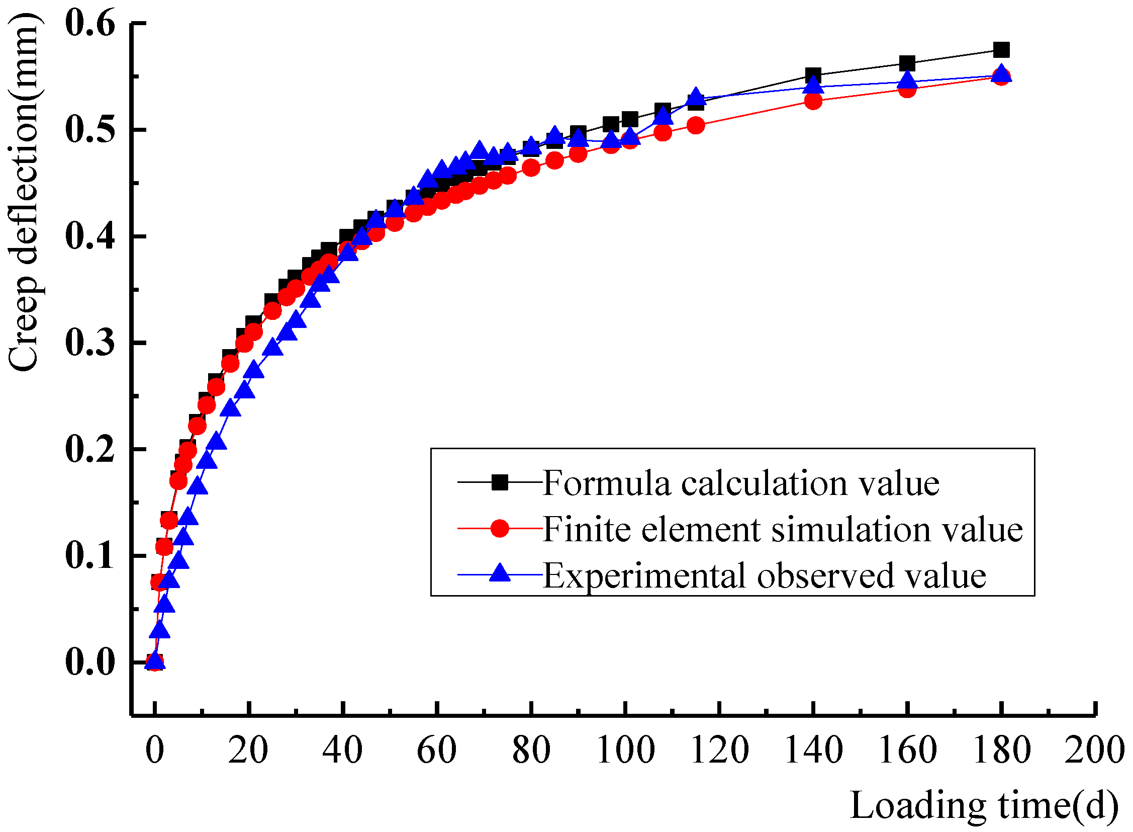
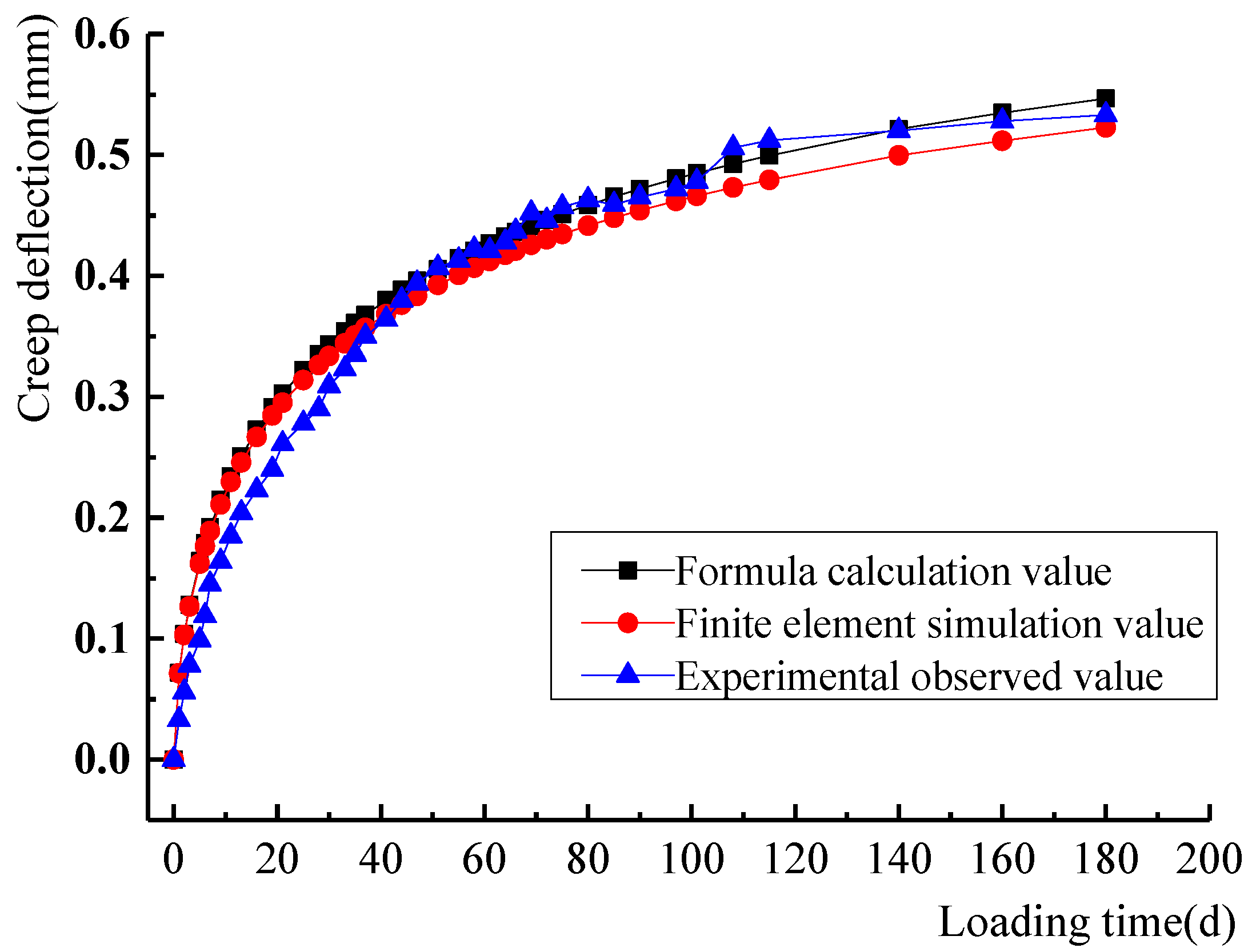
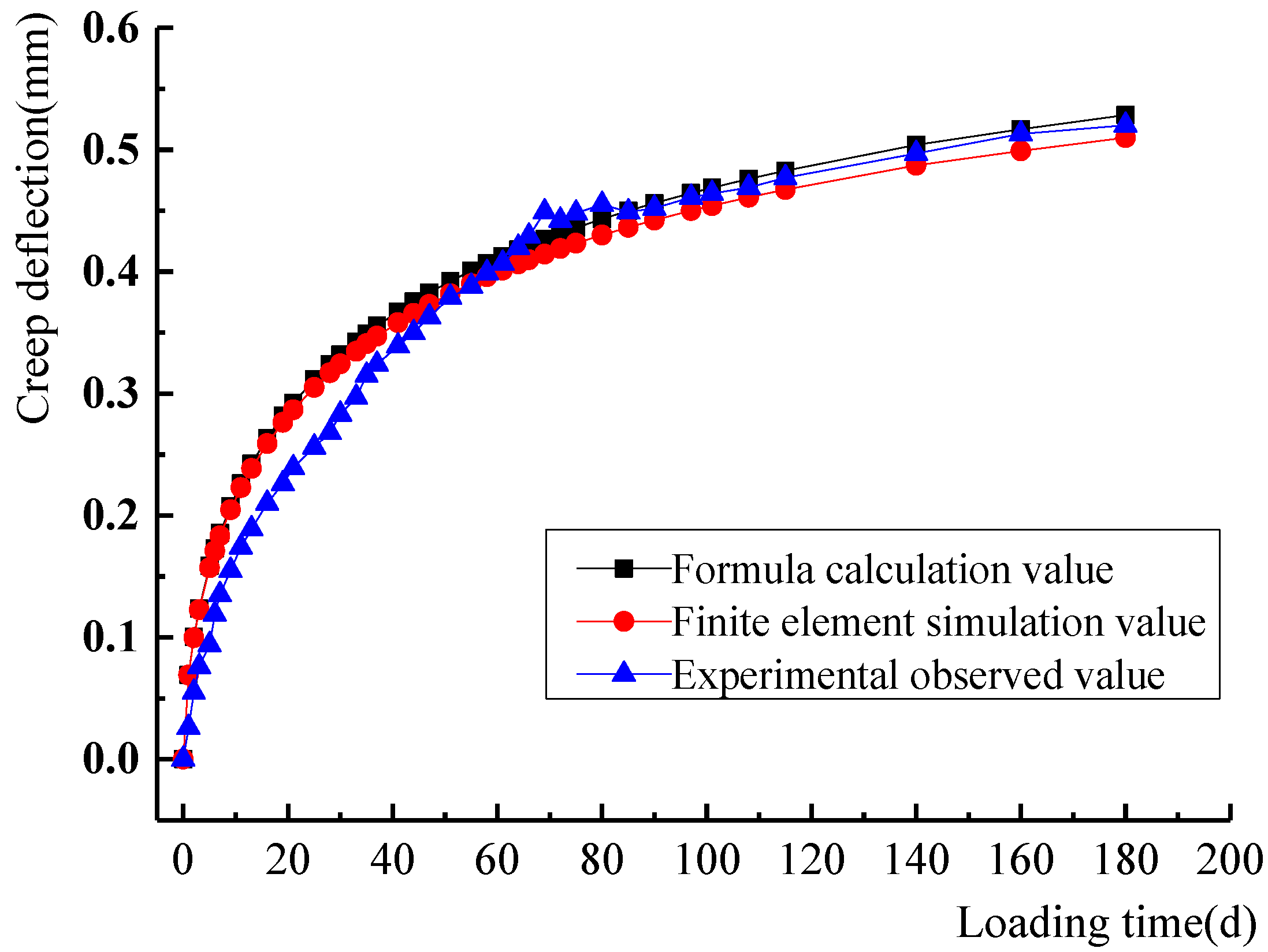
From
Figure 6,
Figure 7,
Figure 8,
Figure 9 and
Figure 10, it demonstrated that the creep calculated based on the calculation formulas of ACI209 and ACI435 were in good agreement with the experimental and numerical simulated data. This suggested that it could better represent the creep variation rules of steel fiber ceramsite concrete beams. Therefore, it can be used as a formula for calculating the creep of ceramsite concrete beams in practical engineering.
5. Numerical Analysis of Long-Term Deformation of Ceramsite Concrete Beam
5.1. Constitutive Relation of Ceramsite Concrete
ABAQUS software was used to model and analyze the long-term deformation of ceramsite concrete beams under load. First, the plastic damage model provided by ABAQUS was used because it can accurately simulate the creep of ceramsite concrete beams [
26]. Then, the stress–strain curve calculation model of concrete under a unidirectional load was used to describe the compression stress–strain curve of the plastic damage model, referring to the “Code for Design of Concrete Structures (GB50010-2019)” in China. The formulas are as follows:
where
;
and
are the stress and strain corresponding to a random point on the curve;
and
are the stress and strain at the vertex of the curve;
is the elastic modulus of concrete; and
and
are the coefficients representing the shape of the curve in the descending part of the curve, which are 3.14 and 1.86, respectively, as referred to in reference [
27].
5.2. Definition of Concrete Damage
Under the effect of the unidirectional compressive load, the compressive damage will occur when the deformation of concrete exceeds the elastic deformation. The calculation formula of the compressive inelastic strain (
) was defined as this: the total compressive strain minus the elastic compressive strain of the material. After the compression damage data was input into ABAQUS, it can be converted into the plastic strain value (
) according to Equation (8).
is calculated by Equation (9).
where
is the initial tangent modulus of concrete, which corresponds to
.
If the plastic strain value output by the program is less than 0 or the inelastic strain decreases, ABAQUS will display an error and stop the operation. When , compression damage will not occur.
The treatment of tensile damage to concrete is similar to that of compressive damage.
5.3. Finite Element Model
The finite element models for each of the five beams were built according to the parameters in
Table 8 and
Figure 1. The concrete was simulated using the 3D eight-node reduced-integration element (C3D8R). The rebar cage was simulated using the 3D two-node truss element (T3D2). The rebar cage was placed inside the concrete slab. Moreover, EMBED bond contacts were applied between the rebar and the surrounding concrete. The constitutive relation and plastic damage of concrete were expressed according to Equations (7)–(9). Poisson’s ratio was taken as 0.2. The concrete creep coefficient was calculated using Equation (1) and imported into the ABAQUS model. The modeling and meshing are shown in
Figure 11.
5.4. Long-Term Loading
Based on the program that comes with ABAQUS, the loading application program for ceramsite concrete beams was simulated using Python. User-defined field variables, state variables and custom expansion options were added to the concrete intrinsic structure definition. Additionally, the fitted creep procedure was written into the modeling file for the subroutine. After each output displacement of the ceramsite concrete beam, the loading state was maintained, the size was unchanged and the next cycle was continued. The variation of the elasticity modulus of ceramsite concrete with time was calculated in real time by using the field and state variables of the material in ABAQUS.
5.5. Finite Element Analysis Results
The parameters of the specimen beams were input into the model. The variation rule of the creep deflection of each model beam with the increase of time was obtained after loading.
5.6. Comparative Analysis of Simulatd, Experimental and Theoretical Value
The creep coefficient was calculated according to the proposed formula of ACI209. Then, the creep value of the beam was calculated by ACI435. From
Figure 6,
Figure 7,
Figure 8,
Figure 9 and
Figure 10, it shows that these values were in good agreement with the experimental and numerical results. In addition, it greatly reflected the creep changes in ceramsite concrete beam.
(1) Comparative analysis of creep at 180 d:
The test results, calculated values and simulated data of each specimen beam at 180 d are shown in
Table 11.
Table 11 and
Figure 6,
Figure 7,
Figure 8,
Figure 9 and
Figure 10 indicated that the theoretical and simulated values of creep of ceramsite concrete beams in these 180 days were close to the experimental results (the errors were within 5%). This showed that the finite element simulation can effectively analyze the creep variation patterns of ceramsite concrete beams. Meanwhile, Formulas (1)–(6) based on the method of ACI209 and ACI435 can be used as a predictive model for the creep of vitrified concrete beams. Moreover, they can fully predict the variations of creep values of ceramsite concrete beams over time.
(2) Comparative analysis of creep curve of deflection time:
It can be seen from
Figure 6,
Figure 7,
Figure 8,
Figure 9 and
Figure 10 that the creep variation rule of ceramsite concrete beam simulated by the finite element model was in good agreement with the results calculated referring to the ACI209 and ACI435 models. The finite element simulation value was slightly lower than the calculated value. The experimental value was in good agreement with the simulated and the calculated value. It was further shown that Formulas (1)–(6) based on the calculation method of ACI209 and ACI435 can well reflect the creep change in the ceramsite concrete beam, as well as the finite element model.
6. Conclusions
Long-term deformation tests, theoretical analysis and finite element modeling were carried out on five ceramsite concrete beams with different V/Ss. The following conclusions were obtained:
(1) The creep of ceramsite concrete specimens developed rapidly in the early stage of loading, but it gradually slowed down over time and tended to be stable after loading for 120 days.
(2) The V/S had an obvious influence on the creep of ceramsite concrete beams. In the first 7 days, the growth rate of each beam was roughly the same. The higher the V/S was, the lower the creep performance was. After 28 days, the creep of each beam was significantly different. When the volume–surface ratio exceeded 30, the increasing V/S can effectively decrease the creep and creep growth rate under long-term loading. In practical engineering, the V/S of the beam can be increased by controlling the beam length and increasing the beam width or height as appropriate to reduce the creep of the beam.
(3) The creep calculation Formulas (1)–(6) of ceramsite concrete beam were established according to the method of ACI209 and ACI435. The calculated results were in good agreement with the measured values, which can well reflect the creep variation rule of ceramsite concrete beams. This formula can be used for the calculation of creep in the design of ceramsite concrete beams.
(4) After adding 0.5% steel fiber, the creep law of ceramsite concrete beams can still be expressed by the modified formulas of ACI209 and ACI435.
(5) The finite element simulation can fully verify the calculation formula of creep and the influence of V/S on the creep of ceramsite concrete beams.
(6) The experiments, theory and numerical simulation in this paper initially revealed the findings that the creep of steel fiber ceramsite concrete beam was influenced by the V/S of the specimen. However, the quantities of specimens were small. As a result, the further experimental studies were planned to be carried out subsequently.
In the future, it will be planned to pour more steel fiber ceramsite concrete beams to expand the study scope of V/S. A combination of experiments and numerical simulations will be used to investigate the effect of V/S on the 180 d creep value of the beams. Furthermore, it can establish equations and reasonably predict the optimum V/S. The results are hoped to provide a scientific reference for engineering design. Moreover, the amount of steel fibers and the relative humidity of the environment may affect the creep of steel fiber ceramsite concrete beams, which will be viewed as the subsequent research directions.
Author Contributions
Conceptualization, X.L. and H.Z.; Methodology, X.L. and H.Z.; Software, P.L.; Validation, Z.F. and C.X.; Formal Analysis, X.L.; Investigation, C.X.; Resources, C.X. and X.L.; Data Curation, C.X., X.L. and H.Z.; Writing—Original Draft Preparation, X.L.; Writing—Review and Editing, X.L. and H.Z.; Visualization, C.X.; Supervision, X.L.; Project Administration, H.Z.; Funding Acquisition, H.Z. All authors have read and agreed to the published version of the manuscript.
Funding
This study was funded by the National Natural Science Foundation of China (grant numbers 51778630, 52178182 and U1934217), China Railway Science and technology research and development plan project (grant numbers 2020-Major project-02, 2021-Major project-02, 2021-Key projects-11) and Hubei Provincial Education Science Planning Project (2019GB201).
Institutional Review Board Statement
Not applicable.
Informed Consent Statement
Not applicable.
Data Availability Statement
The data presented in this study are available on request from the corresponding author.
Conflicts of Interest
The authors declare no conflict of interest.
References
- Bu, C.; Zhu, D.; Liu, L.; Lu, X.; Sun, Y.; Yan, Z.; Yu, L.; Wei, Q. A study on the mechanical properties and microcosmic mechanism of basalt fiber modified rubber ceramsite concrete. Buildings 2022, 12, 103. [Google Scholar] [CrossRef]
- Liu, X.; Meng, K.; Zhang, A.; Zhu, T.; Yu, C. Bearing capacity of H-section beam wrapped with ceramsite concrete. Steel Compos. Struct. 2021, 40, 679–696. [Google Scholar] [CrossRef]
- Xie, Y.; Long, G.; Zhou, Q.; Chaktrimongkol, P.; Shi, Y.; Umar, H. Experimental investigation on mechanical property and microstructure of ultra-high-performance concrete with ceramsite sand. Struct. Concr. 2021, 11, 156. [Google Scholar] [CrossRef]
- Bu, C.; Yang, H.; Liu, L.; Zhu, D.; Sun, Y.; Yu, L.; Ouyang, Y.; Cao, X.; Wei, Q. Quantification of ceramsite granules in lightweight concrete panels through an image analysis technique. Materials 2022, 15, 1063. [Google Scholar] [CrossRef]
- Zhu, H.; Fu, Z.; Liu, P.; Li, Y.; Zhao, B. Shear behavior of stud-PBL composite shear connector for steel–ceramsite concrete composite structure. Coatings 2022, 12, 583. [Google Scholar] [CrossRef]
- Mohebbi, A.; Graybeal, B.; Haber, Z. Time-dependent properties of ultrahigh-performance concrete: Compressive creep and shrinkage. J. Mater. Civ. Eng. 2022, 34, 04022096. [Google Scholar] [CrossRef]
- Mei, S.Q.; Wang, Y.F.; Zhang, J.C. Creep of concrete-filled steel tube considering creep-recovery of the concrete core. Adv. Struct. Eng. 2020, 23, 997–1009. [Google Scholar] [CrossRef]
- Liang, S.M.; Wei, Y. Methodology of obtaining intrinsic creep property of concrete by flexural deflection test. Cem. Concr. Compos. 2019, 97, 288–299. [Google Scholar] [CrossRef]
- Wang, S.R.; Wu, X.G.; Yang, J.H.; Zhu, S. Acoustic emission characteristics and dynamic damage constitutive relation of shale-ceramsite concrete subjected to loading Tests. J. Mater. Civ. Eng. 2020, 32, 76. [Google Scholar] [CrossRef]
- Hwang, E.; Kim, G.; Koo, K.; Moon, H.; Choe, G.; Suh, D.; Nam, J. Compressive creep and shrinkage of high-strength concrete based on limestone coarse aggregate applied to high-rise buildings. Materials 2021, 14, 5026. [Google Scholar] [CrossRef]
- Ye, L.; Sun, H.L.; Lu, X.Z. High Strength Lightweight Aggregate Concrete Structures: Performance, Analysis and Calculation; Science Press: Beijing, China, 2009. [Google Scholar]
- Chen, P.; Zheng, W.Z.; Zhou, X.Y. Creep of reinforced high-strength concrete-containing industrial by-products silica fume and slag. Struct. Concr. 2020, 2, 201900435. [Google Scholar] [CrossRef]
- Zou, D.J.; Liu, T.J.; Teng, J.; Du, C.C.; Li, B. Influence of creep and drying shrinkage of reinforced concrete shear walls on the axial shortening of high-rise buildings. Constr. Build. Mater. 2014, 55, 46–56. [Google Scholar] [CrossRef]
- Li, K.F.; Yang, C.Q.; Huang, W.; Zhao, Y.B.; Wang, Y.; Pan, Y.; Xu, F. Effects of hybrid fibers on workability, mechanical, and time-dependent properties of high strength fiber-reinforced self-consolidating concrete. Constr. Build. Mater. 2021, 277, 122325. [Google Scholar] [CrossRef]
- Cai, X.; Jiang, M.M.; Guo, X.W.; Chen, J.J.; Zhao, Q. Experimental study on the creep behaviour of cemented sand and gravel (CSG) and temperature stress prediction of CSG dam under seasonal temperature change. Adv. Civ. Eng. 2020, 1, 8289520. [Google Scholar] [CrossRef]
- Zheng, Z.H.; Hu, D.; Liu, P.; Sha, F.; Liu, L.; Yu, Z.W. Considering the effect of the randomness of concrete strength and relative humidity on concrete creep. Struct. Concr. 2020, 10, 201900435. [Google Scholar] [CrossRef]
- Zhang, R.; Ma, L.; Wang, Q.; Li, J.; Wang, Y.; Chen, H.; Samosvat, V. Experimental studies on the effect of properties and micro-structure on the creep of concrete-filled steel tubes. Materials 2019, 12, 1046. [Google Scholar] [CrossRef] [Green Version]
- Zhuang, Y.Z.; Chen, C.Y.; Ji, T. Effect of shale ceramsite type on the tensile creep of lightweight aggregate concrete. Constr. Build. Mater. 2013, 46, 13–18. [Google Scholar] [CrossRef]
- Ji, T.; Chen, C.Y.; Chen, Y.B. Effect of ceramsite prewetting degree on tensile creep characteristics of lightweight aggregate concrete. J. Build. Mater. 2012, 15, 690–696. [Google Scholar]
- James, A. Prediction of Creep, Shrinkage and Temperature Effects in Concrete Structures; ACI Committee 209: Farmington Hills, MI, USA, 1992. [Google Scholar]
- Grouni, H.N. Control of Deflection in Concrete Structures; ACI Committee 435: Detroit, MI, USA, 1995. [Google Scholar]
- Sun, G.J.; Xue, S.D. Experimental investigation of creep and shrinkage of reinforced concrete with influence of reinforcement ratio. Adv. Concr. Constr. 2019, 7, 211–218. [Google Scholar]
- Jiang, W.; Yang, Z.H. Compressive creep of lightweight aggregate concrete at early age. J. Build. Mater. 2016, 19, 40–44. [Google Scholar]
- Wang, W.L.; Li, J.T.; Peng, W.J. Effects of water-to-cement ratio, curing method and fiber on the autogenous shrinkage of early-age concrete. J. Ceram. Process. Res. 2019, 20, 77–85. [Google Scholar] [CrossRef]
- Gedam, B.A.; Bhandari, N.M.; Upadhyay, A. An APT material model for drying shrinkage and specific creep of HPC using artificial neural network. Struct. Eng. Mech. 2014, 1, 97–113. [Google Scholar] [CrossRef]
- Nie, J.G.; Wang, Y.H. Comparison study of constitutive model of concrete in ABAQUS for static analysis structures. Eng. Mech. 2013, 30, 59–67. [Google Scholar]
- Zhao, S.B.; Zhao, M.S.; Zhang, X.Y. Study on complete stress curves of steel fiber reinforced lightweight aggregate concrete under uniaxial compression. J. Build. Struct. 2019, 40, 181–190. [Google Scholar]
Figure 1.
Structure of ceramsite concrete beam (Unit: mm). (a) Elevation. (b) Cross section.
Figure 1.
Structure of ceramsite concrete beam (Unit: mm). (a) Elevation. (b) Cross section.
Figure 2.
Loading diagram (Unit: mm).
Figure 2.
Loading diagram (Unit: mm).
Figure 3.
Snapshots of loading. (a) Front view. (b) Side view.
Figure 3.
Snapshots of loading. (a) Front view. (b) Side view.
Figure 4.
Curves of creep deflection–loading time of test beams with different V/Ss.
Figure 4.
Curves of creep deflection–loading time of test beams with different V/Ss.
Figure 5.
Influence of V/S on creep deflection.
Figure 5.
Influence of V/S on creep deflection.
Figure 6.
Creep-time curve of specimen TBB1.
Figure 6.
Creep-time curve of specimen TBB1.
Figure 7.
Creep-time curve of specimen TBB2.
Figure 7.
Creep-time curve of specimen TBB2.
Figure 8.
Creep-time curve of specimen TBB3.
Figure 8.
Creep-time curve of specimen TBB3.
Figure 9.
Creep-time curve of specimen TBB4.
Figure 9.
Creep-time curve of specimen TBB4.
Figure 10.
Creep-time curve of specimen TBB5.
Figure 10.
Creep-time curve of specimen TBB5.
Figure 11.
Finite element model and meshing of ceramsite concrete beam.
Figure 11.
Finite element model and meshing of ceramsite concrete beam.
Table 1.
Physical properties of shale ceramsite.
Table 1.
Physical properties of shale ceramsite.
Particle Size
/mm | Volume Density /(kg⋅m−3) | Apparent Density /(kg⋅m−3) | Compressive Strength of Concrete Cylinder/MPa | Water Absorption
in 1 h/% |
|---|
| 5~20 | 814 | 1517 | 6.8 | 2.42 |
Table 2.
Physical properties of sand.
Table 2.
Physical properties of sand.
| Apparent Density/(kg⋅m−3) | Volume Density/(kg⋅m−3) | Mud Ration/% | Fineness Number |
|---|
| 2650 | 1570 | ≤2 | 2.7 |
Table 3.
Basic physical index of cement.
Table 3.
Basic physical index of cement.
| Density/(g⋅cm−3) | Mineral Composition of Clinker | Fineness (Sieve Allowance by 80 μm Square Hole)/% |
|---|
| C3S | C2S | C3A | C3AF |
|---|
| 3.15 | 45 | 25 | 12 | 8 | 6.5 |
Table 4.
Physical properties of steel fiber.
Table 4.
Physical properties of steel fiber.
| Length/mm | Ratio of Length-Diameter | Density/(g⋅cm−3) | Tensile Strength/MPa | Material |
|---|
| 30 | 60 | 7.8 | ≥1100 | low carbon steel |
Table 5.
Technical index of water-reducing agent.
Table 5.
Technical index of water-reducing agent.
| Color | PH | Relative Density | Solid Content/% | Water-Reducing Rate/% |
|---|
| Pale yellow | 6~8 | 1.08 ± 0.02 | 40 | 25–35 |
Table 6.
Mixed proportion of ceramsite concrete beam specimens (Unit: kg/m3).
Table 6.
Mixed proportion of ceramsite concrete beam specimens (Unit: kg/m3).
| Cement | Ceramsite | Sand | Water-Reducing Agent | Water | Ratio of Fiber Content |
|---|
| 540 | 554 | 730 | 7.02 | 152 | 39 (0.5%) |
Table 7.
The mechanical parameters of ceramsite concrete at 28 d.
Table 7.
The mechanical parameters of ceramsite concrete at 28 d.
| Mechanical Parameters | Strength |
|---|
| Specimen No. 1 | Specimen No. 2 | Specimen No. 3 | Test Results |
|---|
| Compressive strength/MPa | 43.82 | 42.57 | 43.12 | 43.17 |
| Flexural strength/MPa | 7.71 | 7.63 | 7.84 | 7.73 |
| Elasticity modulus/GPa | 2.46 | 2.40 | 2.42 | 2.43 |
Table 8.
Main parameters of test beam.
Table 8.
Main parameters of test beam.
| Specimens | Length/mm | Width/mm | Height/mm | V/S
/mm | Loading Force/kN |
|---|
| TBB1 | 1500 | 100 | 120 | 26.316 | 3.25067 |
| TBB2 | 1500 | 100 | 150 | 28.846 | 4.45055 |
| TBB3 | 1500 | 100 | 180 | 30.823 | 5.65043 |
| TBB4 | 1500 | 120 | 180 | 34.351 | 5.70859 |
| TBB5 | 1500 | 150 | 180 | 38.793 | 5.76675 |
Table 9.
Initial deflection, 180 d total deflection, creep deflection and residual deflection of the beams.
Table 9.
Initial deflection, 180 d total deflection, creep deflection and residual deflection of the beams.
| Specimens | V/S
/mm | | | | |
|---|
| TBB1 | 26.316 | 1.3503 | 1.8426 | 0.5513 | 1.0233 |
| TBB2 | 28.846 | 1.2064 | 1.6845 | 0.5331 | 0.9562 |
| TBB3 | 30.823 | 1.1031 | 1.5673 | 0.5202 | 0.8765 |
| TBB4 | 34.351 | 0.9452 | 1.3238 | 0.4106 | 0.6585 |
| TBB5 | 38.793 | 0.8761 | 1.1645 | 0.2994 | 0.5544 |
Table 10.
Value of influence coefficient of creep coefficient.
Table 10.
Value of influence coefficient of creep coefficient.
| Specimens | | | | | | | Ultimate Creep Coefficient
|
|---|
| TBB1 | 0.6547 | 0.868 | 1.0967 | 1.0180 | 0.8832 | 1.009 | 1.3287 |
| TBB2 | 1.0742 | 1.045 | 1.3478 |
| TBB3 | 1.0574 | 1.090 | 1.3839 |
| TBB4 | 1.0291 | 1.144 | 1.4136 |
| TBB5 | 0.9964 | 1.171 | 1.4010 |
Table 11.
Comparison of creep value at 180 d.
Table 11.
Comparison of creep value at 180 d.
| Number of Test Beam | Test Values | Calculated Values | Error between Calculated and Test Values/% | Finite Element Simulation Values | Error between Simulated and Test Values/% |
|---|
| TBB1 | 0.5513 | 0.5749 | 4.36 | 0.5497 | 0.02 |
| TBB2 | 0.5331 | 0.5467 | 2.63 | 0.5227 | 1.88 |
| TBB3 | 0.5202 | 0.5285 | 1.54 | 0.5099 | 1.92 |
| TBB4 | 0.4106 | 0.3960 | 3.41 | 0.3946 | 3.90 |
| TBB5 | 0.2994 | 0.2982 | 0.33 | 0.2890 | 3.34 |
| Publisher’s Note: MDPI stays neutral with regard to jurisdictional claims in published maps and institutional affiliations. |
© 2022 by the authors. Licensee MDPI, Basel, Switzerland. This article is an open access article distributed under the terms and conditions of the Creative Commons Attribution (CC BY) license (https://creativecommons.org/licenses/by/4.0/).


