Article

Robust Superhydrophobic Coating with Mullite Fiber Framework

1
School of Materials Science and Engineering, Changsha University of Science & Technology, Changsha 410014, China
2
China Institute of Atomic Energy, Beijing 102400, China
*
Author to whom correspondence should be addressed.
Coatings 2022, 12(7), 1037; https://doi.org/10.3390/coatings12071037
Submission received: 26 June 2022 / Revised: 15 July 2022 / Accepted: 20 July 2022 / Published: 21 July 2022
(This article belongs to the Special Issue Recent Advances in Hydrophobic Coatings)

Abstract

:
Superhydrophobic surfaces have received increasing attention due to their excellent water repellency, but the fragile stability of superhydrophobic coatings has been a huge hindrance to their applications. In this work, we constructed a layer of mullite fibers on the surface of a ceramic substrate using high-temperature molten salt. Then, we obtained a superhydrophobic surface with a contact angle greater than 150° via soaking the sample with an alcoholic sol containing modified particles. On the one hand, this interlaced three-dimensional fiber structure increases the surface area and roughness, providing more locations for attaching superhydrophobic particles, as well as improving the water repellency. On the other hand, this fiber layer has a height difference, which protects the superhydrophobic particles attached at lower positions, and when an external object contacts the surface, it gives priority to the stable mullite fibers, reducing the direct contact between superhydrophobic particles and external objects and improving the stability of the superhydrophobic coating. After abrasion with sandpaper, the sample with the mullite fiber layer showed excellent stability compared to the samples without the fiber layer, indicating the significant protective effect of the fiber layer. This paper provides a potential method to enhance the stability of superhydrophobic ceramic surfaces.

1. Introduction

Superhydrophobic surfaces refer to surfaces with a contact angle greater than 150° and a rolling angle less than 10°. The excellent water repellency provides superhydrophobic surfaces with great potential for applications in anti-icing, corrosion resistance, anti-fouling, self-cleaning, and oil-water separation [1,2,3,4,5,6,7]. There are many biological surfaces in nature that have superhydrophobic surfaces. Biological surfaces have excellent water repellency from their fine texture [8]. Inspired by biology and the need for practical applications, many methods to formulate artificial superhydrophobic surfaces have been reported. These methods can be summarized into two types: one based on surface roughness and one based on low-surface energy coatings through chemical etching, laser, and hydrothermal methods [9,10,11]. It has been reported that rough structures were etched on glass–ceramic surfaces with hydrofluoric acid and treated with silane to obtain superhydrophobic surfaces [12]. Another approach is to build a superhydrophobic surface in one step on the surface by preparing a rough, low-surface-energy coating on the substrate surface or by building a rough structure directly on the hydrophobic substrate, using methods such as sol–gel, immersion, and spraying [13,14,15,16]. Lai et al. soaked fabrics in Polydimethylsilane (PDMS) emulsion to obtain superhydrophobic fabrics in one step [17]. Zhang et al. constructed surfaces with both a rough structure and low surface energy using long-chain organosilanes on the surface [18]. The presence of nanostructures has been suggested to increase the surface contact angle as well as reduce the roll angle [19], which has led to an increasing interest in many nanostructured or micro/nanostructured superhydrophobic surfaces. For example, modified nanoparticles sprayed directly onto the material surface can be easily and effectively prepared to obtain superhydrophobicity on the surface [20]. Zhu et al. found that micro/nano-synergistic structures can generate upward Laplace forces that can drive condensate droplets off the surface [21].
Although artificially prepared superhydrophobic surfaces have excellent water repellency, they face the problems of a fragile surface, rough structure, and the easy peeling of the hydrophobic film layer, making it difficult to apply them practically on a large scale. Researchers have devised several strategies to improve the stability of superhydrophobic surfaces. For example, the addition of “glue” enhances the annual enrichment between the superhydrophobic coating and the substrate. It is reported that hydrophobic particles added with “glue” are used for spraying to obtain superhydrophobic surfaces with better stability than those directly sprayed onto the particles [22]. Liu et al. pressed modified superhydrophobic particles into the substrate “glue” under pressure to enhance the peel resistance of the superhydrophobic coating [23]. Three-dimensional-printed superhydrophobic materials of various shapes also have excellent mechanical stability but are difficult to apply to coatings [24,25]. In addition, researchers have worked to design highly stable superhydrophobic coatings that are stable against peeling [26,27,28]. However, these methods cannot avoid the direct contact of external objects with superhydrophobic coatings, which results in limited stability improvement. Deng et al. proposed micro/nanostructures that play different roles, with the micron framework playing a protective role and the nanostructures playing a hydrophobic role, so that when external objects touch the surface, they preferentially touch the micron framework structure, and the nanostructures do not come into direct contact with the external world to prepare a highly stable superhydrophobic surface [29].
Inspired by the design strategy of the “frame” structure, we want to build framework structures with similar functionality through simpler and more common methods with the aim that such framework structures can work in conjunction with other highly stable superhydrophobic coatings. We constructed a layer of mullite fibers on the surface of the Al2O3 ceramic substrate with molten salt. Then, we impregnated the surface with an alcohol sol containing modified particles to obtain a superhydrophobic surface with a contact angle greater than 150°. On the one hand, this interlaced fiber structure greatly enhances the surface area and roughness of the surface, providing more locations for attaching superhydrophobic particles as well as improving the water repellency. On the other hand, the height difference of the mullite layer forms a frame structure to protect the superhydrophobic particles attached at lower positions, and when an external object touches the surface, it gives priority to the mullite fibers at higher positions, which reduces the direct contact between the superhydrophobic particles and external objects and improves the stability of the superhydrophobic surface. We hope to further enhance the mechanical stability of superhydrophobic surfaces by adding this protective framework structure to the highly stable superhydrophobic coating.

2. Experimental Part

2.1. Main Raw Materials

Silica particles (SiO2, ≥99.5%); sodium sulfate (Na2SO4, AR); aluminum sulfate (Al2(SO4)3, AR); ammonia (25%~28%), and 1H, 1H, 2H, 2H-Perfluorodecyltriethoxysilane (PFDTS (≥96%)) were obtained from Macklin Biochemical Technology Co., Ltd., Shanghai, China. Al2O3 ceramic, 40 mm × 40 mm × 2 mm, was obtained from Sien Special Ceramics Co., Ltd., Suzhou, China.

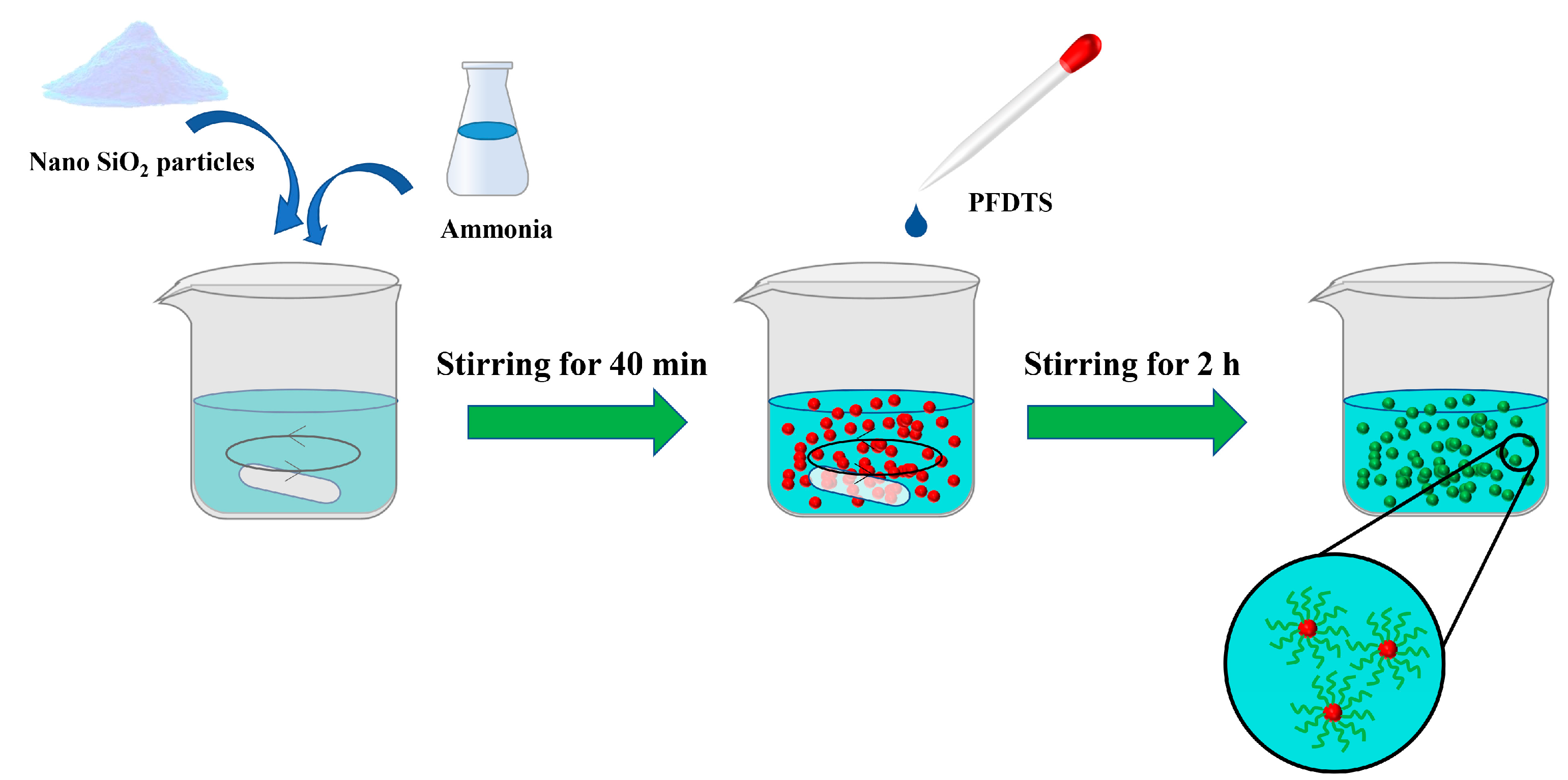
2.2. Preparation of Alcoholic Sols

As shown in Figure 1, 0.2 g nano-silica and 1 mL ammonia were added to 60 mL ethanol and stirred magnetically for 40 min at room temperature; then, 0.5 mL PFDTS was added and continued to be stirred for 2 h to obtain the modified alcohol sol.

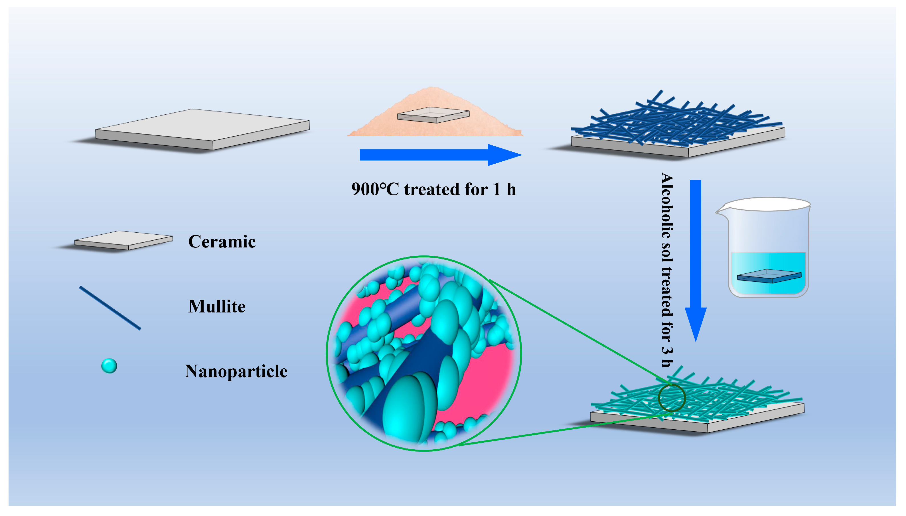
2.3. Sample Preparation

Na2SO4, Al2(SO4)3, and nano-SiO2 were mixed thoroughly according to the ratio shown in Table 1. The mixed salt of equal mass to the ceramic was spread onto the ceramic surface and heat treated at 5 °C/min to 900 °C for 1 h in air, and the ceramic surface was cleaned with hot water after cooling. The cleaned ceramics were immersed in alcohol sol for 3 h, and then heat treated at 200 °C for 1 h for drying and curing to obtain superhydrophobic samples (Figure 2).

2.4. Characterization Methods

The surface roughness and line roughness were measured using a laser confocal microscope (Olympus-ols4100, Tokyo, Japan). Sa is the surface roughness and Ra is the line roughness. The surface micromorphology of the samples was observed with a field emission scanning electron microscope (SEM, JSM-7900F, JEOL, Tokyo, Japan). The wettability of the sample surface was assessed by using an optical contact angle meter (SDC-350, Dongguan Dongsheng Tube Company, Dongguan, China) with a volume of 1.5 μL water. The reported values are the average of three independent measurements. Transmission electron microscopy (TEM, Tecnai G2 F20, FEI, Hillsboro, OR, USA) was used to observe the morphology and crystal structure of the mullite fiber. The chemical structure of the nanoparticles after modification was characterized using infrared spectroscopy (Vertex 70, Bruker, Rheinstetten, Germany). X-ray diffraction (XRD) (D8 Advance, Bruker AXS, Germany) was applied for the crystallographic analysis of the samples, with XRD curves recorded at a scan rate of 5°/min over a 2θ range of 10 to 80°.
The abrasion resistance of the sample surface was tested by pressing the sample with a 100 g weight and moving it horizontally on 800 mesh sandpaper and recording the change in the contact angle of the sample with the moving distance. The contact angle was measured every 4 h by irradiating the prepared superhydrophobic surface with UV light (UV irradiation with 200 W xenon lamp was used). To test the self-cleaning performance of the superhydrophobic surface, 3 g powder (The hydrophilic walnut shell powder was used for self-cleaning evaluation.) was evenly sprinkled onto the surface of the sample, and then 3 mL water was dripped onto the surface to observe the change in the powder on the surface with the amount of water dripped. K2CO3 and HCl solutions of different pH were prepared to simulate different chemical environments in order to test the chemical stability of the samples.

3. Results and Discussion

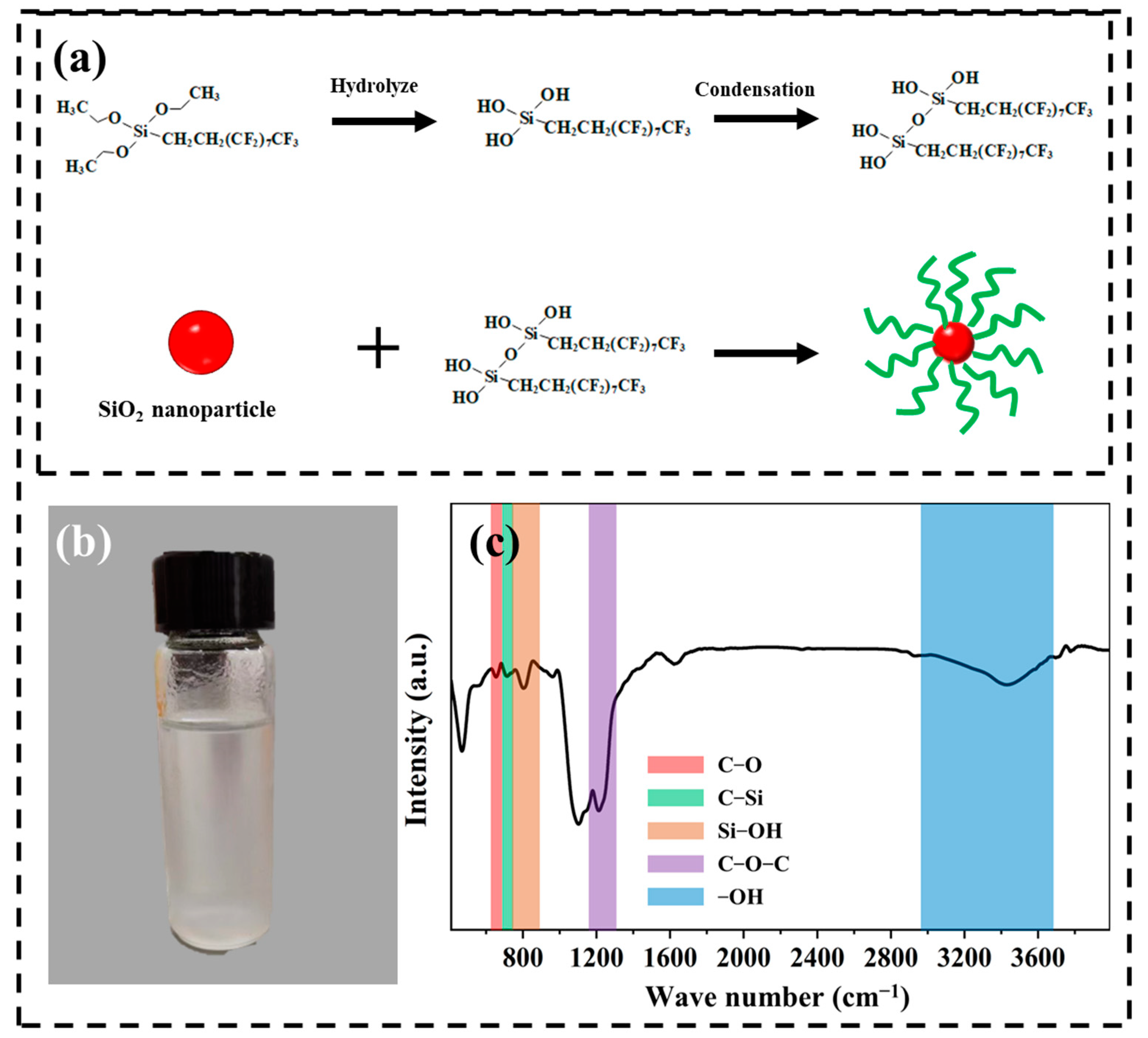
3.1. Nano-Silica Properties after PFDTS Modification

The TEM results (Figure S1) show that the size of the particles was approximately 10 nm, and the atomic arrangement of the particles showed a typical amorphous structure.
The unmodified SiO2 nanoparticles were highly hydrophilic due to their high surface energy in the form of water, which was in the form of hydroxyl groups adsorbed on the surface. Silanes are often used as surface modifiers for hydrophobic materials due to their low surface energy and ease of binding to the substrate. As Figure 3a depicts the modification process of the particles, PFDTS first underwent hydrolysis in ethanol, and the ethoxy group attached to the silicon atom was removed and turned into a hydroxyl group; then, part of the hydroxyl group on PFDTS polymerized with other hydrolysis products, and part of it bound to the particles and was fixed on the surface of the particles [30]. Figure 3b shows a digital photograph of the alcoholic sol-containing nanoparticles. Figure 3c shows the FTIR spectra of the particles after modification. The peak representing -OH in the range of 3000–4000 in the graph is very faint, indicating that there were fewer hydroxyl groups on the surface of the particles, which is because the original -OH on the surface of the particles was combined with PFDTS after modification. The peaks represent C-O, Si-C, C-O-C, and Si-OH [31,32,33,34], which all occurred due to PFDTS, indicating that PFDTS was well bonded to the surface of the particles.

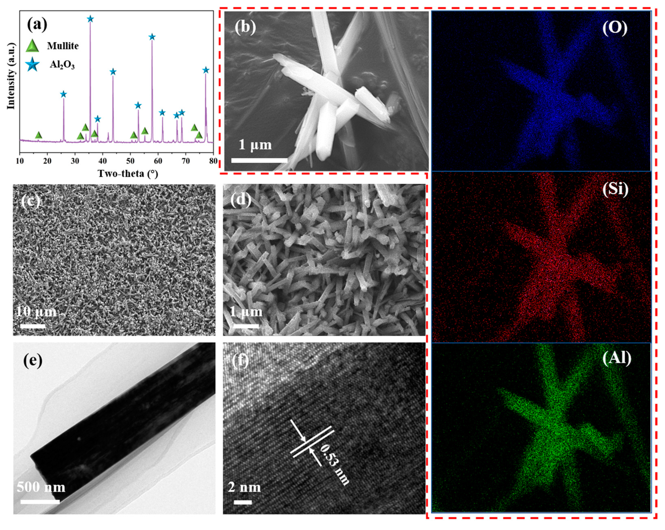
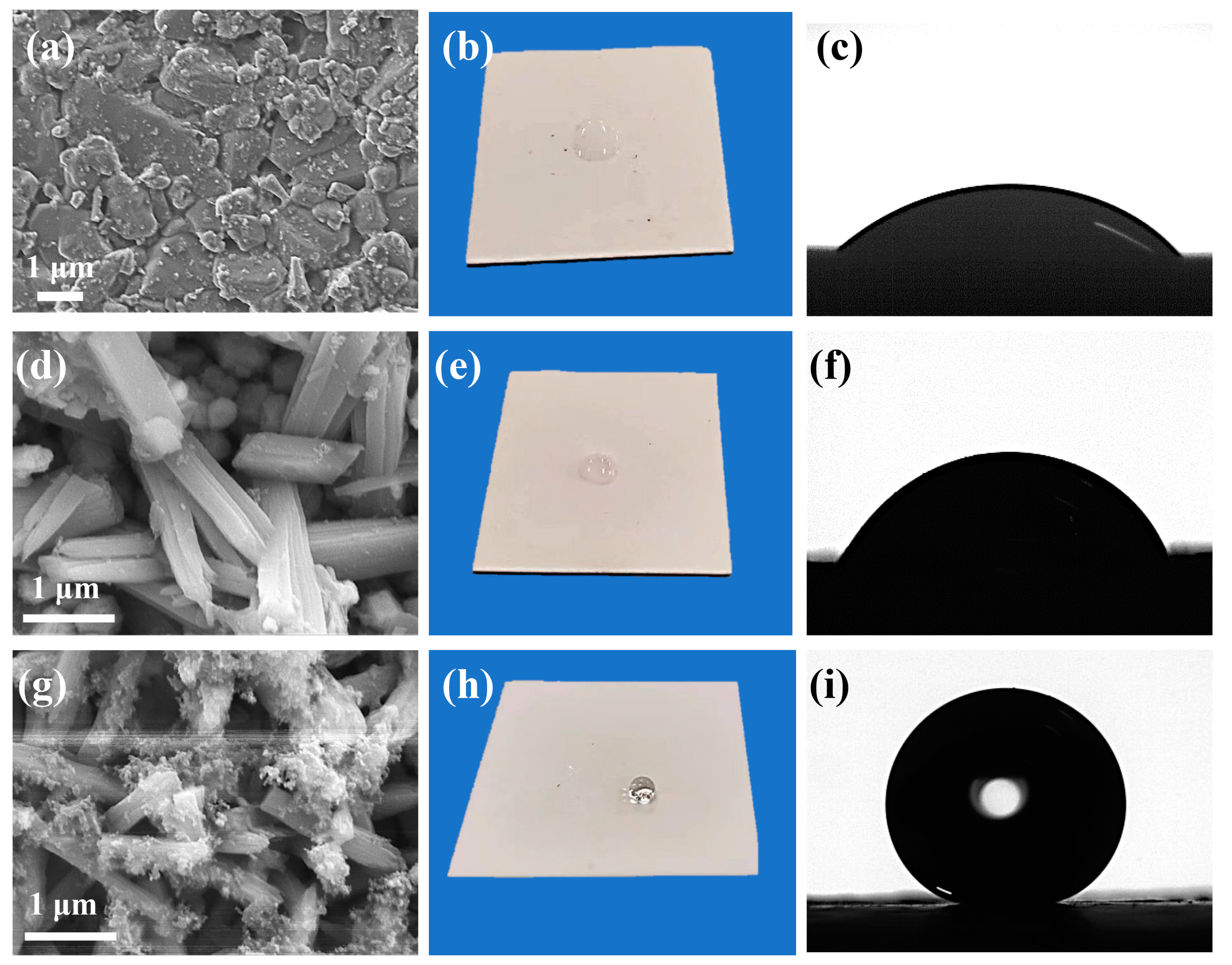
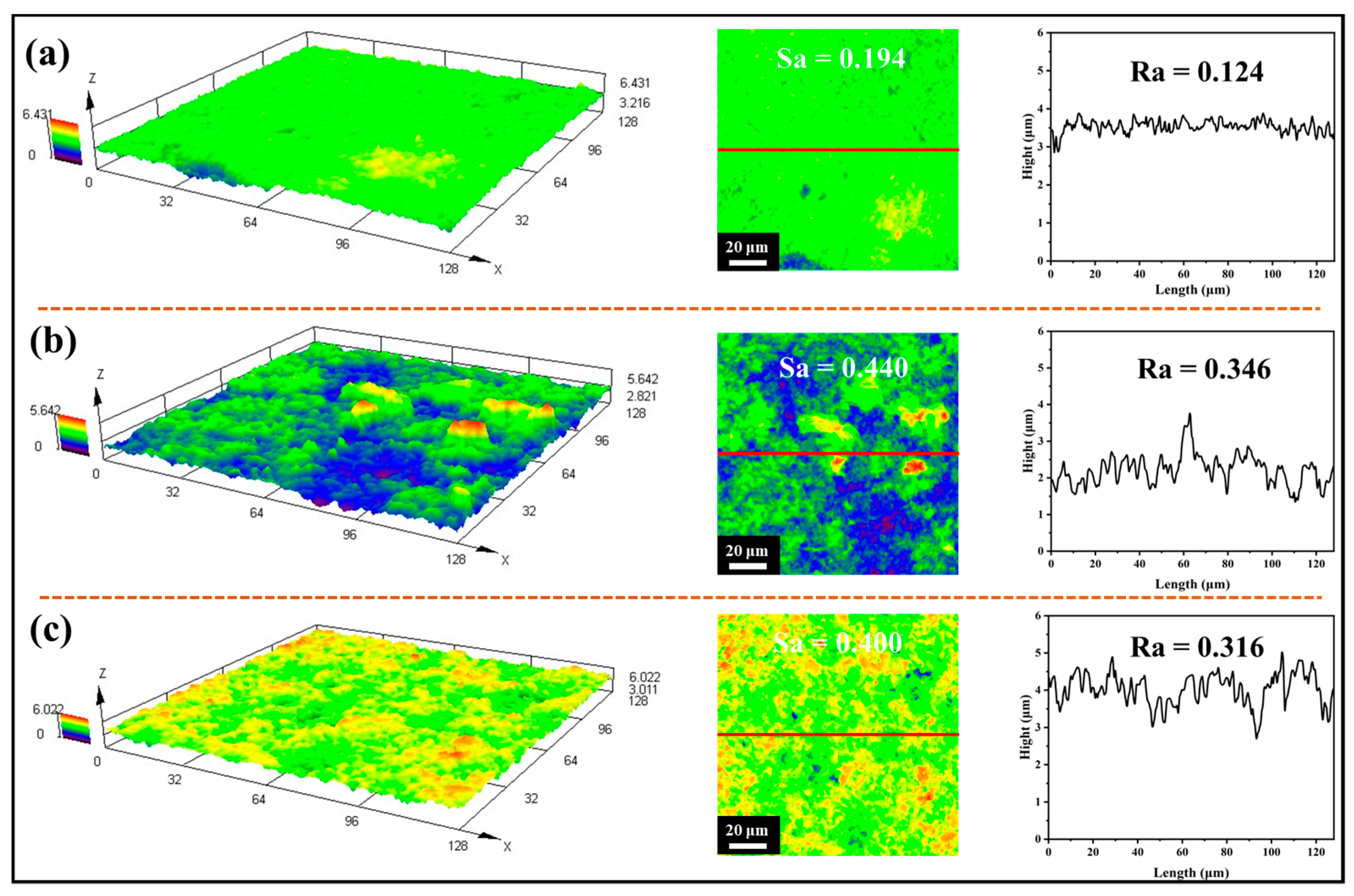
3.2. Characterization of Mullite Layer

Mullite fiber usually requires temperatures above 1200 °C to be prepared [35], but the molten salt method can prepare mullite fibers at lower temperatures and growth on the ceramic surface [36]. According to Yang et al. [37], the decomposition of Al2O3 from Al2(SO4)3 and SiO2 in molten salt reaches an atomic level of mixing, and then, a chemical reaction occurs to produce mullite. In the process of mullite generation, the free energy of reaction (2) is less than 0, which means that mullite can be formed spontaneously if the decomposition of Al2(SO4)3 occurs in Al2O3. Figure S2 shows a schematic diagram of the mullite formation process, in which first the alumina decomposed from aluminum sulfate in the molten salt reacted with the added SiO2 anti-generation to produce mullite nuclei, and then the nuclei gradually grew into mullite.
Al 2 ( SO 4 ) 3 Al 2 O 3 + 3 SO 3
3 Al 2 O 3 + 2 SiO 2 3 Al 2 O 3 · 2 SiO 2 ( Mullite )
Figure 4a shows the XRD pattern of the alumina ceramics after molten salt treatment, and the results indicate that the main phases of the samples were alumina and mullite. Figure 4b shows the SEM morphology and EDS of the prepared mullite fibers, which shows that the prepared mullite fibers had a columnar structure with a length of approximately 1 μm and an aspect ratio of approximately 10:1, and the O, Al, and Si elements were uniformly distributed on the fiber. Figure 4c,d show the microscopic morphology of the sample after the molten salt treatment. There was a layer of dense fibers of 1–2 μm in length on the surface of the ceramic, which is consistent with the fiber morphology in Figure 4b, and the fiber orientation was random, forming a three-dimensional framework structure with voids and providing good conditions for the subsequent coverage of the hydrophobic layer. Combined with the XRD curves, this shows that the surface of the sample was successfully covered with a mullite fiber layer after the molten salt treatment. Figure 4e,f show the TEM morphology and HR-TEM images of the prepared mullite fibers, respectively. As shown in Figure 4f, the lattice stripes were not very clear and there were some black areas, which were due to defects generated during the preparation of mullite fibers. The lattice stripe spacing was 0.53 nm, which was the same as the mullite (001) crystal plane spacing, indicating that the mullite fibers grew along the c-axis.

3.3. Effect of Different Treatments on Surface Wettability

We labeled untreated alumina ceramics, samples grown with the mullite fiber layer, and samples grown with both the mullite layer and hydrophobic layer as S1, S2, and S3, respectively.
Figure 5a–c represent the microscopic morphology and wettability of the S1 sample, which had a relatively flat surface with good crystallinity and a grain size of 1–2 μm, with water droplets spreading on the surface and a contact angle of only 39°, implying that the surface of the untreated ceramic was hydrophilic. Figure 5d–f show the microscopic morphology and wettability of sample S2. The originally flat surface of the sample was covered by a mullite fiber layer, which had a contact angle of 80°. The contact angle of sample S2 was higher than that of S1, probably because the presence of the mullite layer blocked the contact between water and alumina, while the contact angle of mullite itself was higher for water. Figure 5g–i depicts the surface morphology and wettability of the S3 sample, where the originally smooth mullite surface was covered with a layer of nanoparticles. Compared with the direct spraying of particles [30], the particles did not accumulate on the surface and could not enter the mullite interstices, which is more beneficial to improve the stability.
The cross-sectional view (Figure S3) clearly shows the alumina ceramic substrate and mullite layer. The thickness of the mullite layer was approximately 3 μm.
To investigate the effect of roughness on the surface wettability of the samples, the three-dimensional morphology, and the surface and apparent roughness of the S1, S2, and S3 samples were characterized using laser confocal microscopy. Figure 6a shows the morphology and roughness of the S1 sample. As shown by the morphology, the height undulation was small and similar to the surface observed through SEM, and the surface roughness and line roughness were found to be 0.194 and 0.124, respectively. The three-dimensional morphology of the S2 sample showed a greater height undulation than S1, and the surface roughness and line roughness were 0.440 and 0.346, respectively (Figure 6b). This is due to the random orientation of the mullite fibers covering the surface, forming a framework structure that has many voids and bumps, resulting in an increase in surface height difference and an increase in roughness, which means that the surface area also increased, and more locations were available for the hydrophobic film. Figure 6c shows the morphology and roughness of the S3 sample, which demonstrated that the surface height difference was smaller than that of the S2 sample, and the surface roughness and line roughness were 0.400 and 0.316, respectively. The reason for this is that after the superhydrophobic treatment, the nanoparticles and sols were filled into the pores of the surface, resulting in a reduction in the height difference. However, the roughness of the S3 sample is still much larger than S1. For hydrophobic surfaces, the improvement of roughness contributes to water repellency.

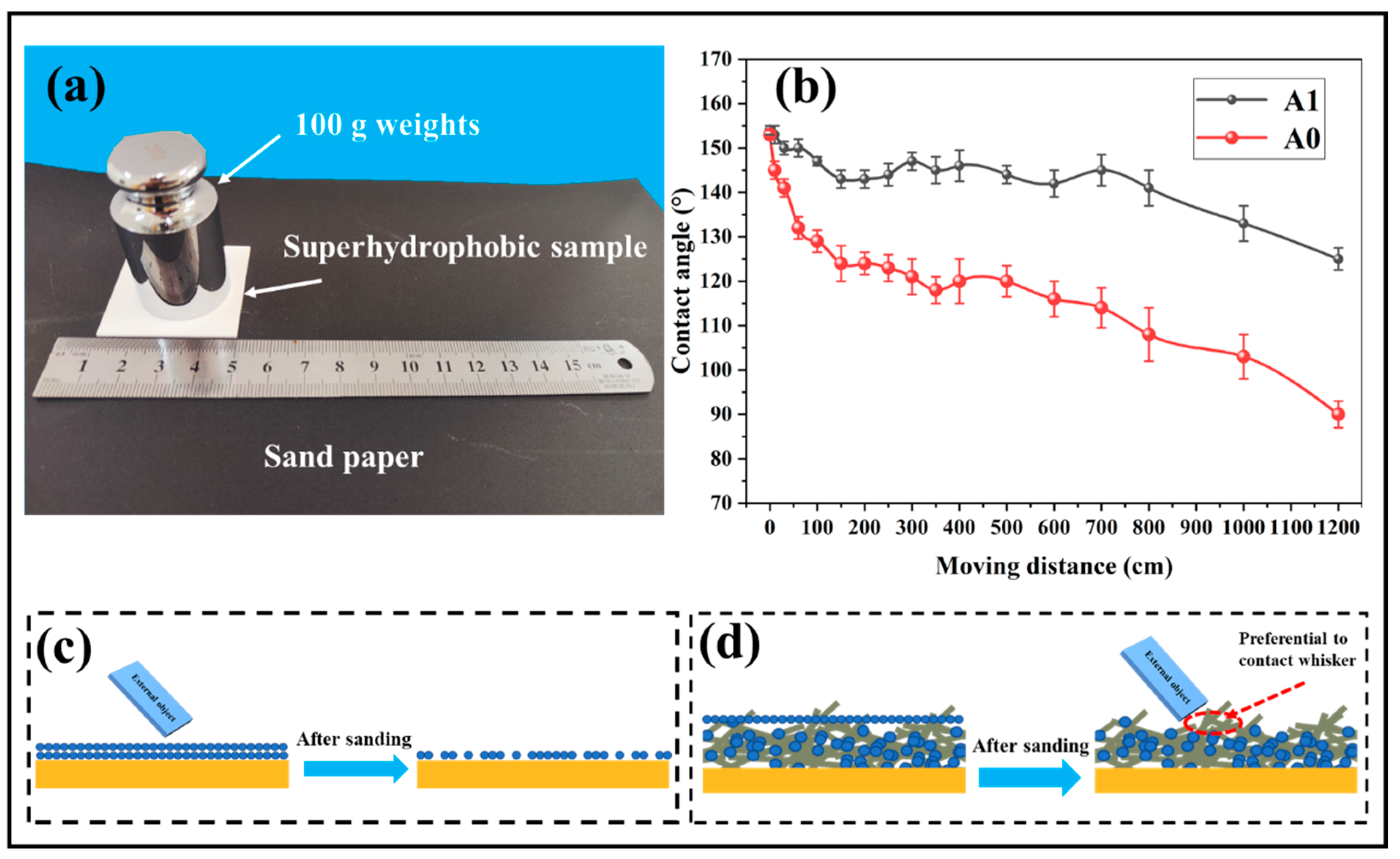
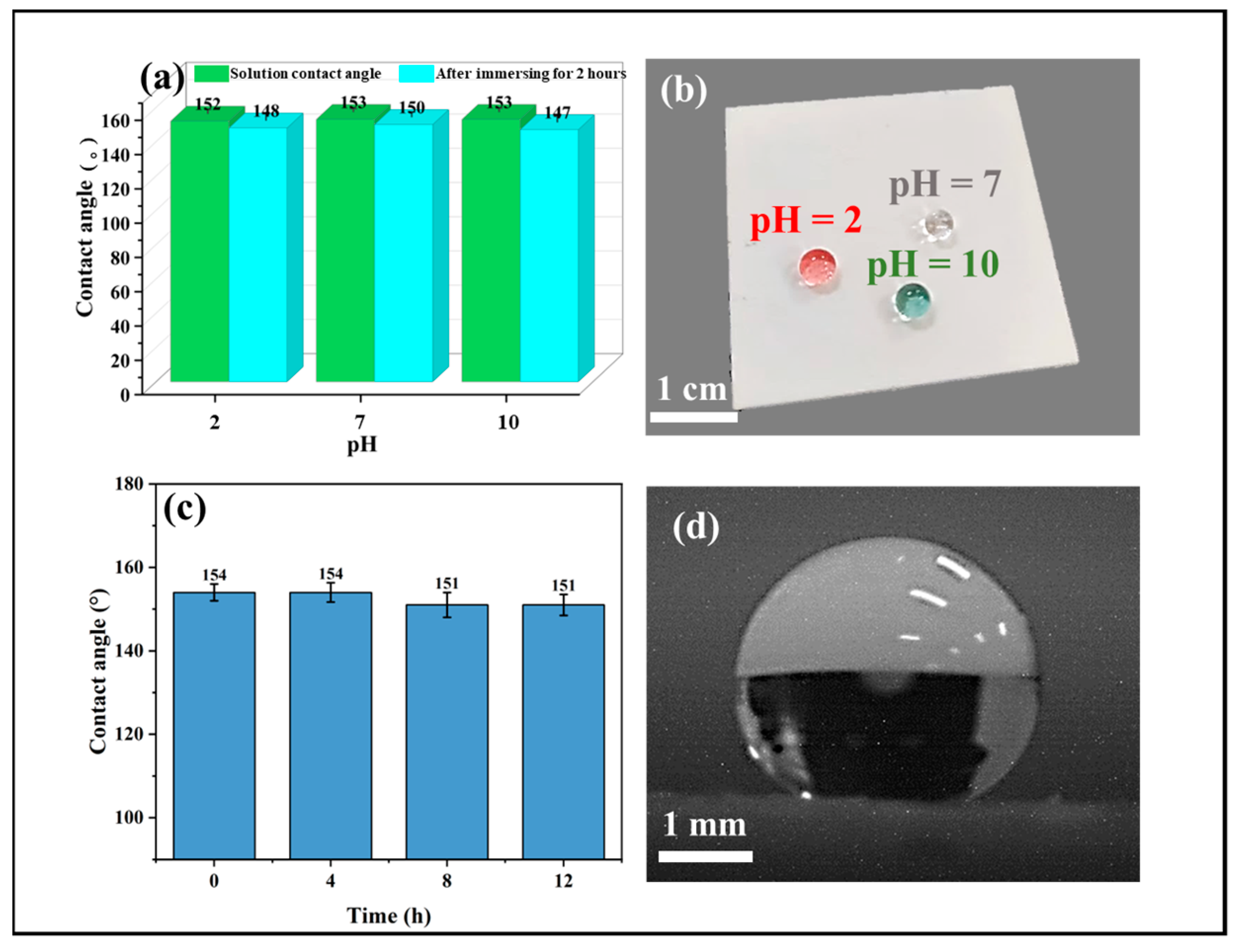
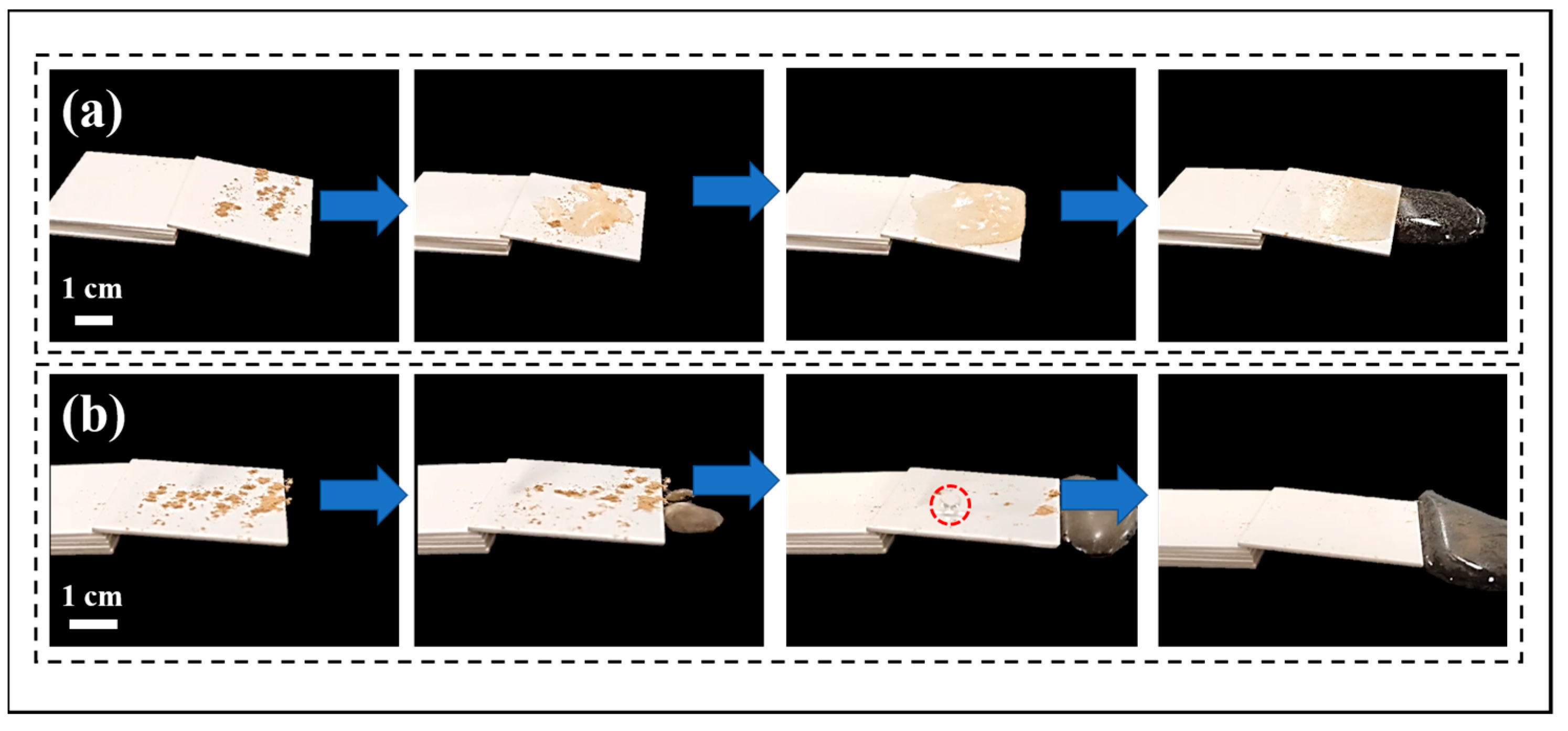
3.4. Self-Cleaning and Stability

Figure 7a shows a digital photograph of a stability test on a superhydrophobic surface, where the samples containing weights covering only the hydrophobic layer (A0) and both the mullite layer and the hydrophobic layer (A1) were pushed horizontally on sandpaper with a horizontal force. Figure 7b shows the test results. The contact angles of the two samples before the test were 152° and 153°, respectively, because the hydrophobic layer completely covered the surfaces of the two samples, at which time the surface morphology was the same, and the contact angles were approximately the same. The contact angles of both samples also gradually decreased in the range of moving distance of 0–200 cm, but the decrease was greater for the A0 sample. When the moving distance exceeded 200 cm, the contact angle of the A0 sample continued to decrease continuously, while the contact angle of the A1 sample remained stable at approximately 145°. When the moving distance reached 1200 cm, the A0 sample had become hydrophilic, and the A1 sample showed a large decrease in contact angle (125°). By the end of the test, the contact angle of the A0 sample was close to the untreated level, while the A1 sample was still hydrophobic. The reason for this is that after sandpaper rubbing, the hydrophobic layer on the surface was destroyed (Figure 7c), and the surface of the A0 sample could only be gradually scraped off, in contrast to the A1 sample, due to the presence of the mullite fiber layer. After the hydrophobic layer covering the fibers was destroyed, the framework structure preferentially made contact with the sandpaper, while the remaining hydrophobic layer was in a lower position in the void and did not make direct contact with the sandpaper, resulting in the surface stability of the sample with the mullite fiber layer being much higher than that of the sample without the fiber layer (Figure 7d). Figure S4 shows that the sliding angle was small when the moving distance was less than 400 cm; the reason for this is that the nanoparticles wrapped around the mullite fibers. The sliding angle gradually increased as the moving distance increased, which is due to the particles being ground off and exposing the hydrophilic fibers.
Figure S5 shows the surface microstructure of the sample after a 1200 cm abrasion. The figure shows that the complete fiber was broken after abrasion, and the fiber layer was partially missing, exposing the substrate. However, the fibers were still present, and there were nanoparticles attached to them; these particles were still able to provide water repellency to the surface.
Figure 8a shows the contact angles of solutions of different pH on the surface of the prepared superhydrophobic samples (Figure 8b is a digital photo) and the contact angles of the samples after 8 h of immersion in solutions of different pH. The results showed that the contact angles of the solutions with different pH exceeded 150° on the sample surface, and after 8 h of immersion, the contact angle of the samples decreased by 4%, the reason for this being that PFDTS is not very stable in water.
Figure 8c shows the effect of different times of UV irradiation on the surface wettability of the samples; the contact angle did not decrease when the irradiation time was 4 h, while the contact angle was 151° when the irradiation time lasted up to 12 h, with a decrease of 1.3%, which means that the prepared superhydrophobic surface has good resistance to UV irradiation.
Figure 9 depicts the comparison of the self-cleaning performance of the untreated ceramic sample and the superhydrophobic sample. The results show that water droplets adhered to the sample surface when dropped on the untreated sample (Figure 9a). As the amount of dripping water increased, the sample surface showed great adhesion to water due to its strong hydrophilic ability, so that the water gathered on the sample surface. When the amount of water drops further increased, the water left the sample surface under the action of gravity, but the powder on the surface was not taken away, and a water film was formed on the sample surface, making the powder more difficult to remove. When all water was dropped onto the superhydrophobic ceramic sample shown in Figure 9b, the water drops rolled off the surface due to the strong water repellency of the sample surface, while taking away the hydrophilic powder together, achieving the purpose of self-cleaning. When the amount of water drops increased, the powder on the surface of the sample was gradually taken away until the surface was completely clean. This shows that the prepared superhydrophobic surface possesses excellent self-cleaning performance.

4. Conclusions

In this work, superhydrophobic surfaces were prepared by forming mullite fiber layers on the surface of alumina ceramics in the molten state with salts containing silicon and aluminum elements, and then immersing the samples in the sol. After sandpaper abrasion tests, the results showed that the samples with the mullite fiber layer were more stable. The reason for this is that the framework structure formed by the mullite layer has many voids as well as bumps. The hydrophobic layer was protected in the lower voids, while the higher bumps were preferentially in contact with external objects. As mullite itself is hydrophilic, the longer the wear time, the more mullite will be exposed, which will lead to a slight decrease in the hydrophobicity of the surface, but it will still be more stable than the superhydrophobic sample without the mullite layer. In addition, the results also demonstrate the good stability of the prepared superhydrophobic surfaces through different chemical environments as well as UV light irradiation tests. The present work provides potential strategies to enhance the stability of superhydrophobic ceramic materials.

Supplementary Materials

The following supporting information can be downloaded at: https://www.mdpi.com/article/10.3390/coatings12071037/s1, Figure S1: (a) TEM morphology of nanoparticles; (b) HR-TEM of nanoparticles; Figure S2: Mullite growth principle; Figure S3: SEM cross-sectional image of S3 sample; Figure S4: The effect of A1 sample moving distance on the sandpaper on the sliding angle; Figure S5: SEM morphology of A1 sample after 1200 cm abrasion test.

Author Contributions

Data curation, W.Z.; Formal analysis, W.Z., M.W. and H.L.; Funding acquisition, H.L. Investigation, W.Z., Q.L., Q.J. and Y.L.; Methodology, W.Z. and B.X.; Resources, S.H. and H.L.; Writing—original draft, W.Z.; Writing—review and editing, S.H. and H.L. All authors have read and agreed to the published version of the manuscript.

Funding

This work is supported by the Defense Science and Technology Industry Nuclear Material Technology Innovation Project (NO. ICNM-2022-ZH-14).

Institutional Review Board Statement

Not applicable.

Informed Consent Statement

Not applicable.

Data Availability Statement

Data is contained within the article or Supplementary Materials.

Acknowledgments

Thanks to eceshi (www.eceshi.com, accessed on 28 June 2022) for the Laser Confocal Microscope analysis.

Conflicts of Interest

The authors declare no conflict of interest.

References

  1. Wang, Y.; Xue, J.; Wang, Q.; Chen, Q.; Ding, J. Verification of icephobic/anti-icing properties of a superhydrophobic surface. ACS Appl. Mater. Interfaces 2013, 5, 3370–3381. [Google Scholar] [CrossRef] [PubMed]
  2. Vazirinasab, E.; Jafari, R.; Momen, G. Application of superhydrophobic coatings as a corrosion barrier: A review. Surf. Coat. Technol. 2018, 341, 40–56. [Google Scholar] [CrossRef]
  3. Lu, Y.; Sathasivam, S.; Song, J.; Crick, C.R.; Carmalt, C.J.; Parkin, I.P. Repellent materials. Robust self-cleaning surfaces that function when exposed to either air or oil. Science 2015, 347, 1132–1135. [Google Scholar] [CrossRef]
  4. Yuan, J.; Liu, X.; Akbulut, O.; Hu, J.; Suib, S.L.; Kong, J.; Stellacci, F. Superwetting nanowire membranes for selective absorption. Nat. Nanotechnol. 2008, 3, 332–336. [Google Scholar] [CrossRef]
  5. Dhyani, A.; Wang, J.; Halvey, A.K.; Macdonald, B.; Mehta, G.; Tuteja, A. Design and applications of surfaces that control the accretion of matter. Science 2021, 373, eaba5010. [Google Scholar] [CrossRef] [PubMed]
  6. McBride, S.A.; Girard, H.L.; Varanasi, K.K. Crystal critters: Self-ejection of crystals from heated, superhydrophobic surfaces. Sci. Adv. 2021, 7, eabe6960. [Google Scholar] [CrossRef] [PubMed]
  7. Zhang, J.; Zhao, J.; Qu, W.; Li, X.; Wang, Z. One-step, low-cost, mussel-inspired green method to prepare superhydrophobic nanostructured surfaces having durability, efficiency, and wide applicability. J. Colloid Interface Sci. 2020, 580, 211–222. [Google Scholar] [CrossRef]
  8. Yu, F.; Wang, D.; Yang, J.; Zhang, W.; Deng, X. Durable Super-repellent Surfaces: From Solid–Liquid Interaction to Applications. Acc. Mater. Res. 2021, 2, 920–932. [Google Scholar] [CrossRef]
  9. Zhong, W.; Liao, H.; Wu, M.; Xiong, B.; Zhan, W. Superhydrophobic surface based on the self-growing structure of BaAl2Si2O8 glass-ceramics. Ceram. Int. 2022, 48, 1990–1998. [Google Scholar] [CrossRef]
  10. Li, X.; Jiang, Y.; Tan, X.; Zhang, Z.; Jiang, Z.; Lian, J.; Wen, C.; Ren, L. Superhydrophobic brass surfaces with tunable water adhesion fabricated by laser texturing followed by heat treatment and their anti-corrosion ability. Appl. Surf. Sci. 2022, 575, 151596. [Google Scholar] [CrossRef]
  11. Yin, X.; Yu, S.; Wang, K.; Cheng, R.; Lv, Z. Fluorine-free preparation of self-healing and anti-fouling superhydrophobic Ni3S2 coating on 304 stainless steel. Chem. Eng. J. 2020, 394, 124925. [Google Scholar] [CrossRef]
  12. Fu, H.; Liu, S.; Yi, L.; Jiang, H.; Li, C.; Chen, Y. A Durable and Self-Cleaning Superhydrophobic Surface Prepared by Precipitating Flower-Like Crystals on a Glass-Ceramic Surface. Materials 2020, 13, 1642. [Google Scholar] [CrossRef] [Green Version]
  13. Xiu, Y.; Hess, D.W.; Wong, C.P. UV and thermally stable superhydrophobic coatings from sol-gel processing. J. Colloid Interface Sci. 2008, 326, 465–470. [Google Scholar] [CrossRef] [PubMed]
  14. Li, A.; Jia, Y.; Zhang, F.; Zhao, Y.; Zhang, F. The Effects of Zinc Oxide/Silicon Dioxide Composite Coating on Surface Wettability and the Mechanical Properties of Paper Mulching Film. Coatings 2022, 12, 555. [Google Scholar] [CrossRef]
  15. Taurino, R.; Fabbri, E.; Pospiech, D.; Synytska, A.; Messori, M. Preparation of scratch resistant superhydrophobic hybrid coatings by sol–gel process. Prog. Org. Coat. 2014, 77, 1635–1641. [Google Scholar] [CrossRef]
  16. Gong, A.; Zheng, Y.; Yang, Z.; Guo, X.; Gao, Y.; Li, X. Spray fabrication of superhydrophobic coating on aluminum alloy for corrosion mitigation. Mater. Today Commun. 2021, 26, 101828. [Google Scholar] [CrossRef]
  17. Gao, S.; Dong, X.; Huang, J.; Li, S.; Li, Y.; Chen, Z.; Lai, Y. Rational construction of highly transparent superhydrophobic coatings based on a non-particle, fluorine-free and water-rich system for versatile oil-water separation. Chem. Eng. J. 2018, 333, 621–629. [Google Scholar] [CrossRef]
  18. Zhang, L.; Zhou, A.G.; Sun, B.R.; Chen, K.S.; Yu, H.Z. Functional and versatile superhydrophobic coatings via stoichiometric silanization. Nat. Commun. 2021, 12, 982. [Google Scholar] [CrossRef]
  19. Feng, L.; Li, S.; Li, Y.; Li, H.; Zhang, L.; Zhai, J.; Song, Y.; Liu, B.; Jiang, L.; Zhu, D. Super-Hydrophobic Surfaces: From Natural to Artificial. Adv. Mater. 2002, 14, 1857–1860. [Google Scholar] [CrossRef]
  20. Yu, X.; Liu, X.; Shi, X.; Zhang, Z.; Wang, H.; Feng, L. SiO2 nanoparticle-based superhydrophobic spray and multi-functional surfaces by a facile and scalable method. Ceram. Int. 2019, 45, 15741–15744. [Google Scholar] [CrossRef]
  21. Tang, Y.; Yang, X.; Li, Y.; Lu, Y.; Zhu, D. Robust Micro-Nanostructured Superhydrophobic Surfaces for Long-Term Dropwise Condensation. Nano Lett. 2021, 21, 9824–9833. [Google Scholar] [CrossRef] [PubMed]
  22. Zhu, R.; Liu, M.; Hou, Y.; Zhang, L.; Li, M.; Wang, D.; Fu, S. One-Pot Preparation of Fluorine-Free Magnetic Superhydrophobic Particles for Controllable Liquid Marbles and Robust Multifunctional Coatings. ACS Appl. Mater. Interfaces 2020, 12, 17004–17017. [Google Scholar] [CrossRef] [PubMed]
  23. Liu, F.; Du, H.; Zhao, X.; Wang, X.; Wang, C.; Liu, Z.; Wang, H. Ultrafast Fabrication of a Robust Superwetting Coating. Ind. Eng. Chem. Res. 2021, 60, 15151–15161. [Google Scholar] [CrossRef]
  24. Dong, Z.; Vuckovac, M.; Cui, W.; Zhou, Q.; Ras, R.H.A.; Levkin, P.A. 3D Printing of Superhydrophobic Objects with Bulk Nanostructure. Adv. Mater. 2021, 33, e2106068. [Google Scholar] [CrossRef]
  25. Jafari, R.; Cloutier, C.; Allahdini, A.; Momen, G. Recent progress and challenges with 3D printing of patterned hydrophobic and superhydrophobic surfaces. Int. J. Adv. Manuf. Technol. 2019, 103, 1225–1238. [Google Scholar] [CrossRef]
  26. Rasitha, T.P.; Philip, J. Optimal condition for fabricating mechanically durable superhydrophobic titanium surface by rapid breakdown anodization: Self cleaning and bouncing characteristics. Appl. Surf. Sci. 2022, 585, 152628. [Google Scholar]
  27. Manoj, T.P.; Rasitha, T.P.; Vanithakumari, S.C.; Anandkumar, B.; George, R.P.; Philip, J. A simple, rapid and single step method for fabricating superhydrophobic titanium surfaces with improved water bouncing and self cleaning properties. Appl. Surf. Sci. 2020, 512, 145636. [Google Scholar] [CrossRef]
  28. Rasitha, T.P.; Vanithakumari, S.C.; George, R.P.; Philip, J. Template-Free One-Step Electrodeposition Method for Fabrication of Robust Superhydrophobic Coating on Ferritic Steel with Self-Cleaning Ability and Superior Corrosion Resistance. Langmuir 2019, 35, 12665–12679. [Google Scholar] [CrossRef]
  29. Wang, D.; Sun, Q.; Hokkanen, M.J.; Zhang, C.; Lin, F.Y.; Liu, Q.; Zhu, S.P.; Zhou, T.; Chang, Q.; He, B.; et al. Design of robust superhydrophobic surfaces. Nature 2020, 582, 55–59. [Google Scholar] [CrossRef]
  30. Xu, M.; Feng, Y.; Li, Z.; Wang, X.; Li, C.; Jiang, H.; Chen, Y. A novel, efficient and cost-effective synthesis technique for the development of superhydrophobic glass surface. J. Alloys Compd. 2019, 781, 1175–1181. [Google Scholar] [CrossRef]
  31. Sun, Y.; Liu, S.; Sun, L.; Wu, S.; Hu, G.; Pang, X.; Smith, A.T.; Hu, C.; Zeng, S.; Wang, W.; et al. Ultralong lifetime and efficient room temperature phosphorescent carbon dots through multi-confinement structure design. Nat. Commun. 2020, 11, 5591. [Google Scholar] [CrossRef] [PubMed]
  32. Maier, G.; Glatthaar, J.; Reisenauer, H.P. Dihalodimethylsilanes from silicon atoms and methyl halides: A combined matrix-spectroscopic and density functional theory study. J. Organomet. Chem. 2003, 686, 341–362. [Google Scholar] [CrossRef]
  33. Marks, J.; Brauman, J.I.; Mead, R.D.; Lykke, K.R.; Lineberger, W.C. Spectroscopy and dynamics of the dipole-supported state of acetyl fluoride enolate anion. J. Chem. Phys. 1988, 88, 6785–6792. [Google Scholar] [CrossRef]
  34. Zhang, Y.; Wu, Y.; Yang, X.; Li, D.; Zhang, X.; Dong, X.; Yao, X.; Liu, J.; Guo, A. High-strength thermal insulating mullite nanofibrous porous ceramics. J. Eur. Ceram. Soc. 2020, 40, 2090–2096. [Google Scholar] [CrossRef]
  35. Wang, W.; Hou, G.; Wang, B.; Deng, S. Preparation of biomorphic silicon carbide–mullite ceramics using molten salt synthesis. Mater. Chem. Phys. 2014, 147, 198–203. [Google Scholar] [CrossRef]
  36. Yang, T.; Chen, J.; Li, L.; Chou, K.-C.; Hou, X. Template free synthesis of highly ordered mullite nanowhiskers with exceptional photoluminescence. Ceram. Int. 2015, 41, 9560–9566. [Google Scholar] [CrossRef]
  37. Zhong, W.; Wu, M.; Xiong, B.; Liu, Q.; Liao, H. High stability superhydrophobic glass-ceramic surface with micro–nano hierarchical structure. Ceram. Int. 2022, 48, 23527–23535. [Google Scholar] [CrossRef]
Figure 1. Preparation process of alcoholic solvents.
Coatings 12 01037 g001
Figure 2. Superhydrophobic ceramic surface preparation process.
Coatings 12 01037 g002
Figure 3. (a) Modification process of superhydrophobic particles; (b) digital photos of alcohol sols; (c) infrared spectra of particles before and after modification.
Coatings 12 01037 g003
Figure 4. (a) XRD pattern of ceramic samples treated with molten salt; (b) SEM and EDS of mullite fibers prepared by molten salt method; (c,d) SEM of ceramic surface treated with molten salt; (e) TEM morphology of mullite fibers prepared by molten salt method; (f) HR-TEM of mullite fibers prepared by molten salt method.
Coatings 12 01037 g004
Figure 5. (ac) SEM morphology and wettability of S1 sample surface (contact angle of 40 ± 3°); (df) SEM morphology and wettability of S2 sample surface (contact angle of 76 ± 2°); (gi) SEM morphology and wettability of S3 sample surface (contact angle of 153 ± 3°).
Coatings 12 01037 g005
Figure 6. (a) 3D surface morphology, 2D morphology, and line roughness of S1 sample; (b) 3D surface morphology, 2D morphology, and line roughness of S2 sample; (c) 3D surface morphology, 2D morphology, and line roughness of S3 sample.
Coatings 12 01037 g006
Figure 7. (a) Digital photos of the superhydrophobic surface stability testing process; (b) the effect of different samples moving distance on the sandpaper on the contact angle; (c) A0 sample scraped by sandpaper model; (d) A1 sample scraped by sandpaper model.
Coatings 12 01037 g007
Figure 8. (a) Contact angle of different pH solutions on the superhydrophobic surface and the contact angle of the samples immersed in different chemical environments after 8 h; (b) Different pH solutions on the surface of the superhydrophobic samples; (c) Effect of UV irradiation time on the contact angle of the superhydrophobic surfaces; (d) The droplets on the surface of the samples after 12 h UV irradiation.
Coatings 12 01037 g008
Figure 9. (a) Self-cleaning process of untreated sample; (b) Self-cleaning process of superhydrophobic sample.
Coatings 12 01037 g009
Table 1. Raw materials of molten salt (wt%).
Na2SO4Al2(SO4)3Nano-SiO2
66.7%29.8%3.5%
Publisher’s Note: MDPI stays neutral with regard to jurisdictional claims in published maps and institutional affiliations.

