Article

Microstructure and Wear Behavior of TC4 Laser Cladding Modified via SiC and MoS2

1
School of Materials Science and Engineering, Southwest Jiaotong University, Chengdu 611756, China
2
AVIC Chengdu Aircraft Industrial (Group) Co., Ltd., Chengdu 610091, China
*
Author to whom correspondence should be addressed.
Coatings 2022, 12(6), 792; https://doi.org/10.3390/coatings12060792
Submission received: 5 May 2022 / Revised: 31 May 2022 / Accepted: 2 June 2022 / Published: 7 June 2022
(This article belongs to the Special Issue Laser Cladding Coatings: Microstructure, Properties, and Applications)

Abstract

:
A TC4 composite coating reinforced by SiC ceramic phase and MoS2 self-lubricating phase was prepared on a muzzle brake by laser cladding to improve its wear resistance properties. In this study, we investigated the microstructure and wear behavior of the composite coating. The results show that the composite coating consisted of equiaxed grains with grain sizes ranging from 102.39 to 255.31 μm on the surface and columnar grains on the bottom. The grains with mesh basket microstructure were mainly with α-Ti and β-Ti phases. When wearing against H70 brass, the main wear mechanism of the composite coating at room temperature was adhesive wear, while the wear mechanism was dominated by adhesive wear, oxidation wear, and slight abrasive wear at high temperature. Compared with TC4 coating without SiC and MoS2, the wear rate of the composite coating was reduced by 15%–35% when the temperature was below 400 °C, and the wear rate was reduced by about 55% at 600 °C, resulting from the addition of SiC. Moreover, the friction coefficient of the composite coating was about 10%, which was 30% lower than that of the substrate and TC4 coating when the temperature was below 400 °C and at 600 °C due to the forming of the dense oxide film and the MoS2 friction transfer film on the friction contact surface of the titanium-based composite coating.

1. Introduction

Titanium alloys are widely used in military, aerospace, marine, chemical, and biomedical equipment industries [1] because of their low density, high specific strength, and corrosion resistance [2]. However, the limitations of titanium alloys, such as low wear resistance and oxidation at high temperature, significantly restrict their service environment and application fields [3,4,5]. In the military field, the high friction coefficient of titanium alloys usually causes damage to the equipment components, which seriously affects weapons accuracy. For example, titanium muzzle brakes and brass shells undergo adhesive wear under high-temperature friction. It damages the performance of the brake and affects the accuracy of the shells. To solve the above problems, surface treatment techniques such as nitriding, carburizing, oxidation, physical vapor deposition, chemical vapor deposition, and ion implantation [6,7,8,9] are often used to improve the surface properties of titanium alloys.
Laser cladding is also used to improve the surface properties of titanium alloys due to the customized powder composition [10]. Many scholars have been working on laser cladding of titanium alloys to obtain coatings with good compatibility, excellent wear resistance, and high-temperature oxidation resistance. N. Jeyaprakash et al. [11] prepared NiCrMoNb and NiCrBSiC coatings on titanium alloys to improve the wear resistance of the cladding layer as the γ-Ni in the coating was mixed with chromium (Cr), silicon (Si), molybdenum (Mo), and boron (B) to form a dendritic eutectic structure. Zhang et al. [12] found that when the Si content was 20%, the NiCrBSi coating on TC4 alloys had the best wear resistance. The increase in the Si content accelerated the transformation of the coating from violent oxidation to slow oxidation. At the same time, it delayed the increase rate of the content of the high hardness phase Ti5Si3 in the oxidation process. However, coatings with Si content higher than 20% had higher cracking susceptibility. Ceramic coating can significantly improve the hardness, wear resistance, and oxidation resistance of titanium alloys [13], but the ceramic coating is easy to crack due to its high brittleness. Therefore, research mainly focuses on composite ceramic coatings, and there has been much work using density functional theory (DFT) to understand wear and structural properties in composite ceramic materials and reveal mechanisms for the strength of structures [14,15]. Yoshitaka Umeno [15] et al. calculated the ideal strength of SiC crystals by first-principles DFT. The effect of the polytype SiC structures on the shear strength of some shear systems appears to be significant, while that on the tensile strength is marginal. Under multi-axial stress conditions, SiC can not only experience cleavage by tension, but also slide due to shear stress, although it is basically brittle. Anand M. Murmu [16] et al. prepared a ZrO2-Al2O3-TiO2 ceramic coating on the TC4 substrate, in which the nano-ZrO2 of the tetragonal phase and monoclinic phase reduced the friction coefficient and improved the hardness and wear resistance. Zhao et al. [17] prepared a TiOx coating, mainly composed of TiOx and Ti, with a small amount of Al2O3, and showed that the cured TiOx coating had extremely high fracture strength, hardness, and excellent wear resistance. Li et al. [18] studied the effect of Al2O3-13%TiO2 on the structure and properties of TiAlSi composite coatings. They found that the stable α-Al2O3 improved the mechanical properties of the coating; a small amount of TiO2 reduced thermal stress, curing shrinkage and cracking tendency; and the hardening phase Ti3AlC2 improved the strength and thermal shock resistance. Zhang et al. [19] used Ni60/20%WS2 powder to prepare a self-lubricating coating on the surface of TC4. During the cladding process, WS2 was decomposed to CrxSy-type compounds and TiS2, in which CrxSy formed a transfer film on the friction surface to achieve the anti-friction effect and TiS2 acted as a lubricant. Moreover, MoS2 reduced the friction coefficient of the Ni-based self-lubricating composite coating and improved the wear resistance by forming a lubricating transfer film during the dry sliding wear process [20].
Great progress has been made in the research of wear-resistant coatings on the surface of laser cladding titanium alloys, but there are still many problems to overcome. As mentioned above, most researchers used laser cladding to improve the surface wear resistance of titanium alloys by adding or generating a ceramic hardening phase with high hardness and high wear resistance in the coating. However, under high temperatures or in an environment where the lubricating medium was not suitable, the coating surface still exhibited a high friction coefficient in wear, which affected the surface quality of the coating itself and the wear parts and reduced the service life of the parts in long-term wear. Therefore, the coating should improve the wear resistance of the surface of the part and have a certain anti-friction performance to satisfy the part’s long-term working under special conditions such as high temperature and vacuum. Nowadays, as the application of titanium alloys becomes more and more widespread, it is necessary to prepare a self-lubricating and wear-resistant composite coating by laser cladding on titanium alloys to improve their wear resistance. However, the lubricating phase can reduce the friction coefficient of the coating, and the excess lubricating phase can reduce the strength and hardness of the coating. Moreover, increasing the hardness of the coating can improve the wear resistance of the coating, but if the content of the hard phase is too high, the brittleness of the coating increases, and fatigue cracking is likely to occur in the process of friction and wear. Many scholars have carried out research on self-lubricating wear-resistant coatings. Dai et al. [21] fabricated self-lubricating TiB2-TiCxNy ceramic coatings on Ti-6Al-4V alloy by laser surface alloying with B4C and graphite powders in nitrogen atmosphere. Gao et al. [22] fabricated Ti-Ni/TiN/TiW + TiS/WS2 self-lubricating wear resistant composite coating on Ti-6Al-4V alloy by laser cladding with NiCrBSi, TiN, and WS2 powder mixtures. Zhu et al. [23] prepared Co-Cu/Ti3SiC2 self-lubricating wear resistant composite coatings on Ti6Al4V alloy by laser cladding. The average microhardness of these coatings has been significantly improved compared with substrate due to the reinforcing phases, and the wear resistance of the coating has also been effectively improved. However, these studies mainly focus on the wear performance and wear mechanism at room temperature, and there are few studies on the wear performance at high temperatures.
The commonly used self-fluxing alloy materials and metal-based ceramic materials have poor compatibility with titanium alloys, which cannot solve the problems of high friction coefficient and easy adhesive wear of titanium alloys. At the same time, the hardness and toughness of the coating cannot be balanced. Therefore, we designed a novel titanium-based composite coating on the muzzle brake by laser cladding to enhance the wear resistance of the coating by adding SiC ceramic phase and MoS2 self-lubricating phase. We explored the high-temperature wear mechanism of the composite coating by analyzing the microstructure, phase structure, microhardness, friction reduction, and wear resistance.

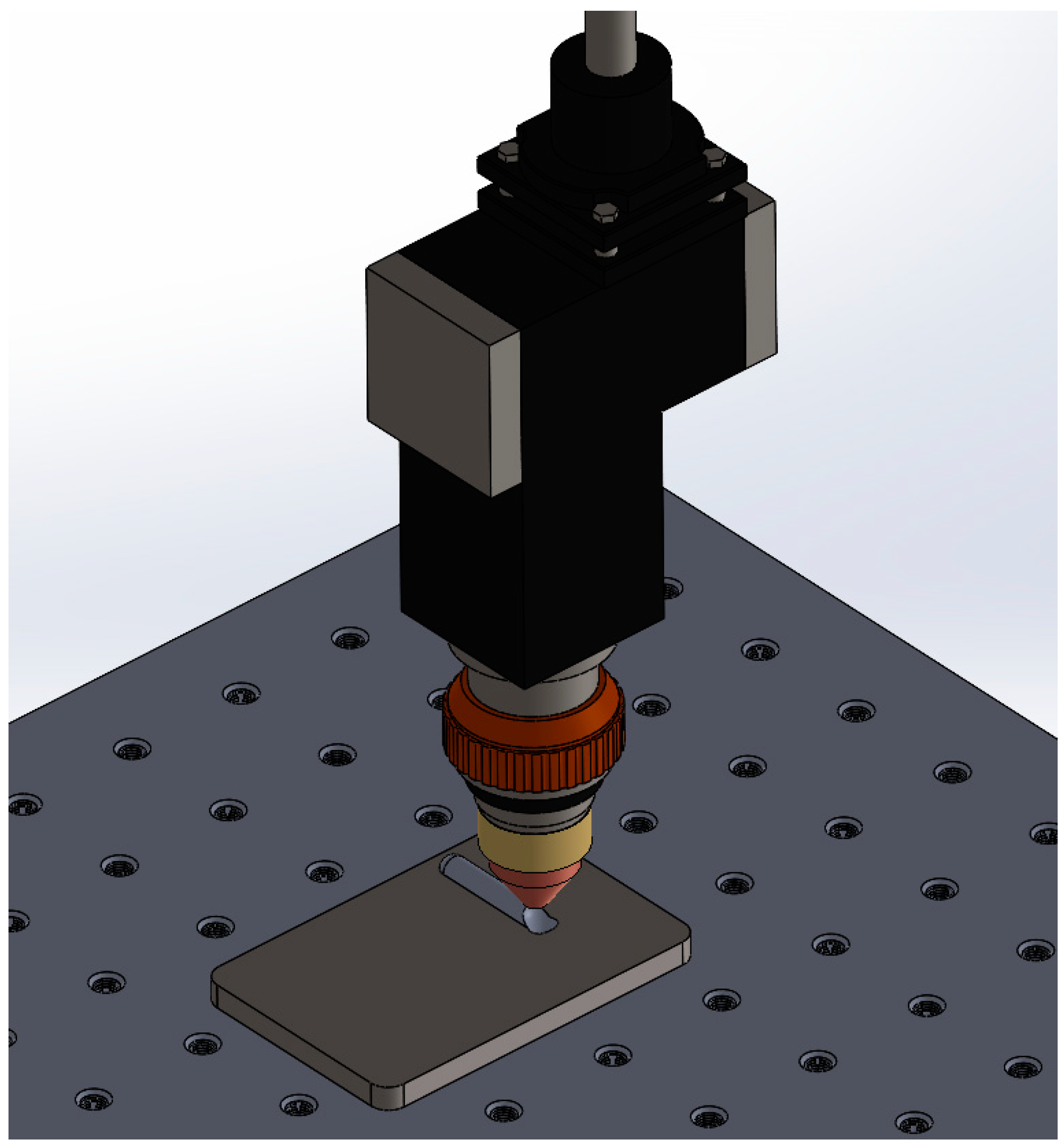
2. Materials and Methods

The substrate was TC4 titanium alloy, and its chemical composition is shown in Table 1. The substrate is a duplex microstructure in the as-cast state, with a size of 170 × 130 × 13 mm. A mixed powder consisting of TC4 powder for suitable compatibility with the substrate, SiC powder for hardening, and Ni-coated MoS2 powder for lubricating was prepared, and its morphologies are shown in Figure 1. The TC4 powder particles have a uniform size of 100–150 μm high sphericity and smooth surface, which provides good fluidity during the cladding process. SiC powder particles with the purity of 99.9% have excellent high-temperature strength, good wear, corrosion resistance, and low cost, and are used to improve the wear resistance of the coating. Because MoS2 was easy to burn during the cladding process, Ni-coated MoS2 was selected as a lubricant phase. The powder contains 25.41% MoS2, and the rest is Ni. The microscopic morphologies of powder particles are shown in Figure 1.
The effect of powder composition on the coating performance was explored through preliminary tests. We found that too high SiC content easily led to the cladding cracking or even peeling off. Excessive MoS2 content caused the formation of large pores, and the presence of Mo reduced the elastic modulus of the Ti-Mo system. Therefore, the powder ratio was determined to be TC4:SiC:Ni-coated MoS2 = 98.5:1:0.5.
The laser cladding system consisted of a YLS-4000 fiber laser, powder feeding system, walking mechanism, and integrated control. The powder feeding system consisted of a TD03 laser cladding synchronous turntable double-cylinder powder feeder, an anti-static powder feeding tube, and a coaxial four-point nozzle. The cladding shielding gas was 99.999% high-purity argon. In the early stage of the experiment, we conducted single-factor experiments and multi-factor orthogonal experiments, through which the optimized process parameters were determined, as shown in Table 2. During the laser cladding process, the substrate was kept at 250 °C. TC4 coatings were prepared using the same process parameters for comparison. The schematic diagram of laser cladding is shown in Figure 2.
The as-deposited composite coating was evaluated for its microstructural characteristics, hardness, tensile properties, and high-temperature wear performance. The metallographic specimen was obtained with 10 mm × 10 mm × 10 mm via a wire-cutting machine, then polished by a series of abrasive paper, and etched by a mixed reagent with HNO3:HF:H2O = 2:3:5 for 10 s. The AIM Zeiss microscope was used to observe the metallographic structure of the cladding layer, and the FEI Nova Nano SEM 400 field emission scanning electron microscope (SEM) was used to observe the microscopic morphology. An energy dispersive spectrometer (EDS) in SEM was used to analyze the types and contents of constituent elements in the selected micro-zones on the surface of the coating and friction and wear samples. The X Pert Pro MPD X-ray diffractometer (XRD) with a Cu target, the voltage being 40 kV, the current being 40 mA, and the scanning step of 0.02°/min was used for the phase analysis of the laser cladding layer. The DHV-1000ZTEST micro-Vickers hardness tester was used to test the microhardness of the coating. The test area was a straight line from the near-surface of the cladding layer to the substrate area. The test load was 1.96 N, lasting for 15 s, and the test point interval was 0.1 mm. In this paper, the thicknesses of the coating, bonding interface, and heat-affected zone (HAZ) were relatively narrow, being only 1–2 mm. The micro-shear method was used to measure the shear strength of each area. The sample size was 1.5 mm × 1.5 mm × 20 mm, and the shearing speed was 1 mm/min. The micro-shear tester was developed by The Welding Laboratory of Southwest Jiaotong University. The high-temperature wear performance was performed by the HT-1000 high-temperature friction and wear tester, which is composed of four parts: a computer control system, a high-temperature furnace, a mechanical friction system, and a loading mechanism. The required load was applied after heating the furnace to the target temperature during the test. Meanwhile, the friction sample fixed on the plate was driven to rotate against the counter surface (ball). In this paper, the diameter of the friction sample was 30 mm and the diameter of the friction pair was 6 mm. The chemical composition of the friction pair was 69.7%–71% Cu, 0.085% Fe, 0.0029% Pb, and the rest was Zn. The test load was 2.94 N, the sliding speed was 6 m/s, and the friction radius was 6 mm. The experimental temperatures were room temperature, 200 °C, 400 °C, and 600 °C, and the experimental time was 10–30 min. The wear volume was obtained by the Bruker Contour GT white light interference three-dimensional profiler. The apparatus information used in this work is listed in Table 3.

3. Results and Discussion

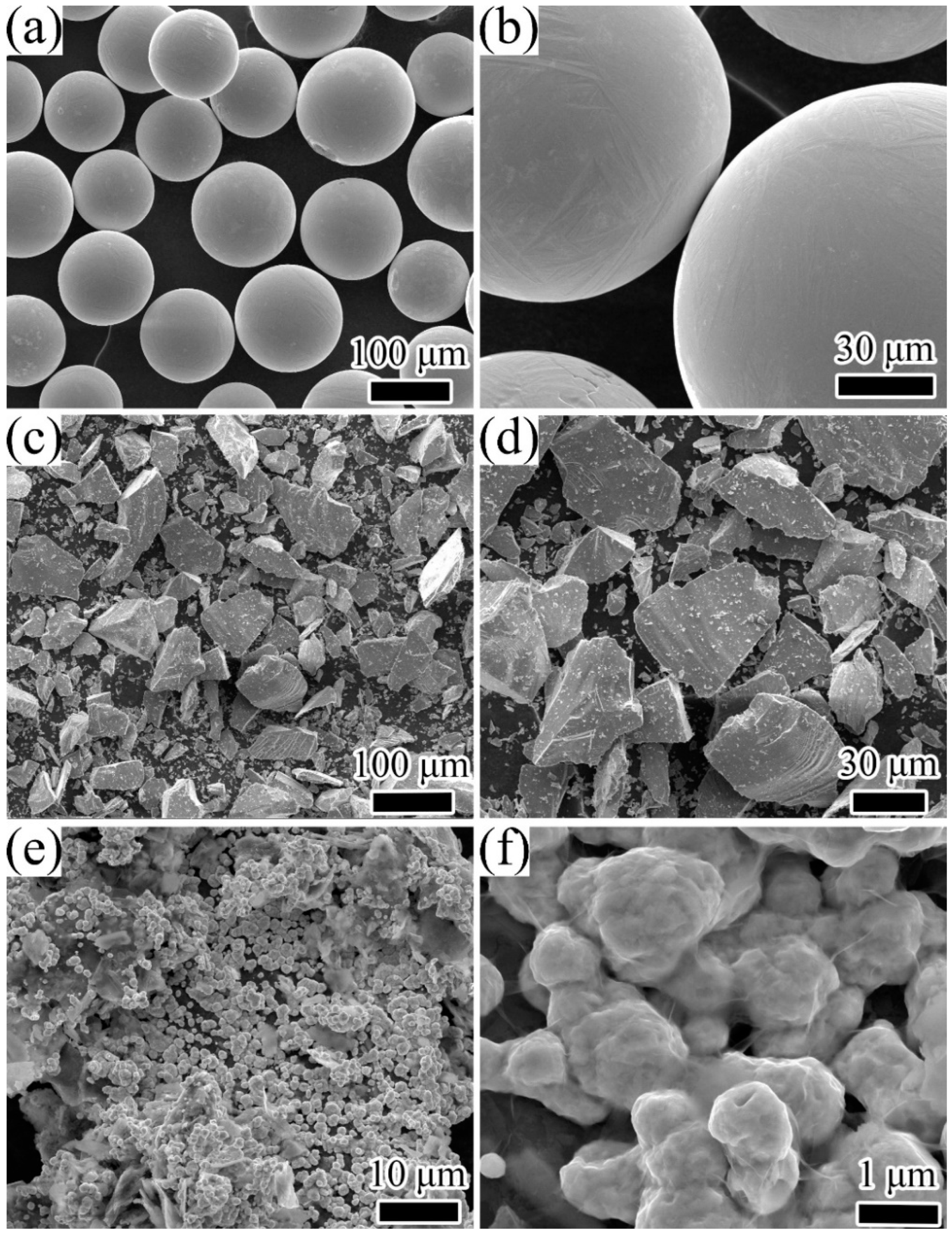
3.1. Microstructural Characteristics of Composite Coating

The XRD phase analysis results of the composite coating prepared with optimized process parameters are shown in Figure 3. The XRD spectra was coincident with phase α-hexagonal-crystal-system Ti (a = b = 2.944 nm, c = 4.678) and Ti3Al (a = b = 5.793 nm. c = 4.649 nm); it exhibited a prominent (101) and (201) peak. The diffraction peaks occurred at 2θ = 35°, 38°, 40°, 53°, 71°, 77°, and 78°, indicating the diffraction of (100), (002), (101), (102), (110), (103), (112), and (201) planes of the α matrix and the diffraction of (200), (002), (201), (202), (212), (311), (222), and (401) planes of the Ti3Al matrix. The major peaks at around 38° indicated a strong presence of β-Ti in the sample, as shown in Figure 3, which indicated the diffraction of (110) planes. Therefore, the main phases in the coating were α-Ti, β-Ti, and Ti3Al. SiC and MoS2 were not detected due to the low content.
The cross-sectional morphology of samples is shown in Figure 4a. The cladding layer was roughly divided into four areas from top to bottom: the coating, the bonding interface, the heat-affected zone (HAZ), and the substrate. There were apparent differences in the microstructures of each area. The reason was that the cladding layer had different temperature gradients and solidification rates at different depths. Because the surface of the cladding layer was in contact with the air, there was convection heat dissipation between them, which led to a high solidification rate, resulting in equiaxed grains. On the contrary, the cladding layer’s heat conduction at the bottom was relatively slow, so it was easy to form columnar grains, and these columnar grains grow directionally [24]. Consequently, from the surface layer to HAZ, the microstructure of each area was different. The microstructure of the surface of the coating exhibited equiaxed grains with the grain sizes ranging from 102.39 to 255.31 μm. The columnar grains were observed at the bottom with the grain length up to 910 μm, and the width ranged from 208.78 to 321.81 μm. The bonding interface (the junction of the cladding material and the substrate) was an excellent metallurgical bond. Figure 4b,c shows the microstructure of the cladding layer under optimized process parameters. It can be seen from Figure 4b that the β phase displayed a fine mesh basket microstructure with clear grain boundary. In Figure 4c, a large number of α-laths and fine white fragments and spheres are present. The EDS detection result in Table 4 showed that the spheres were SiC particles, and the white fragments were Ti3Al. Due to the high cooling rate of laser cladding, the β phase was not totally transformed into the α phase. Some untransformed β phase transformed into a metastable phase α’, and others remained in the β phase structure. The basket-weave and sheet-like α phase with small ratio and staggered arrangement were distributed on the transformed β substrate. Acicular hexagonal martensite was not found in the metallographic structure, which might be attributed to the fact that it was a metastable phase and decomposed into α + β phase at a high temperature as the sample had been kept at 250 °C during the laser cladding process [25]. Ti3Al intermetallic compounds were formed during the phase transformation when the Al content was 5%–25% [26]. In this work, the Al content in the cladding powder system was about 6%, and as a result, Ti3Al precipitated from the molten pool during the solidification of the laser cladding. Zhang et al. [27] generated ultra-fine nanocrystalline Ti3Al in the TC4 coating with the same feature as the fragmented white structure in Figure 4c. The size of Ti3Al in Figure 4c was slightly larger than that due to the larger laser power used in this work. The precipitated Ti3Al was dispersed and distributed in the coating to cause the precipitation strengthening and dispersion strengthening.

3.2. Microhardness and Shear Properties

Figure 5 shows the microhardness of the samples. The dispersion of SiC increased the microhardness to 466.75 HV, which is 1.5 times as high as the substrate. The uneven distribution of SiC and a small number of pores in the coating caused slight fluctuations in the microhardness. The average microhardness of the bonding interface was not much different from the microhardness of the substrate, which was only increased by 10%.
Figure 6 shows the shear curve (load–displacement curve) of each area. The maximum shear stress at fracture was arranged in order of coating, bonding interface, HAZ, and substrate. The fracture of the coating occurred immediately after the maximum load was applied without plastic deformation, indicating that the coating was brittle. On the contrary, both the bonding interface and the HAZ experienced a plastic deformation, crack formation, and propagation.
In the shear test, the deformation of the shear surface varied with the cutting depth into the sample. The brittle and hard sample led to shallow cutting depth and small shear surface deformation. Therefore, the cutting depth and the deformation of the shear surface can reflect the plasticity of the material. In this paper, the indentation rate α was introduced as an index of plasticity. The calculation method was given by the following equation:
α = ( A 0 A k ) A 0 × 100 % ,
where A0 is the cross-sectional area of the sample and Ak is the minimum cross-sectional area after the sample was broken. The smaller the Ak is, the higher the indentation rate α is, which indicates that the material has strong deformability and good plasticity.
Figure 7 shows the shear strength and indentation rate of the prepared cladding samples. The shear strength gradually decreases from coating, bonding interface, HAZ, to substrate. The indentation rate arranged in order from large to small was bonding interface, HAZ, coating, and substrate. Ti3Al was dispersedly distributed in the coating. Ti3Al has a hexagonal close-packed crystal structure, and only one slip system at room temperature, which results in the plasticity of the coating being lower than that of the bonding interface. The strength and plasticity of the coating were better than those of the substrate, which indicated that the coating and the substrate were well bonded. Moreover, the bonding interface had a higher plastic deformation capacity than that of the substrate.
The shear fracture morphology of the coating is shown in Figure 8. The macroscopic morphology of the fracture was relatively smooth with evident shear bands and parabolic ductile dimples. The macroscopic morphology exhibited a rock-like pattern with a strong three-dimensional effect in area A, where the grain boundary and lots of pores in the fracture could be observed. According to area B in Figure 8a, a large number of small planes on the grain boundary of the fracture surface were found, suggesting that the fracture of the coating was a brittle intergranular fracture.

3.3. Formatting of Mathematical Components

The friction coefficient, wear rate, and wear scar morphology of composite coatings, TC4 coating, and substrate were investigated by wear against H70 brass, which is the main component of the outer wall of the shell. The wear mechanism and the high temperature wear resistance of the composite coating were explored.

3.3.1. The Influence of Temperature on Friction Coefficient

The friction coefficients of three samples’ wear against H70 brass at different temperatures are shown in Figure 9. At the beginning of wear, the contact surface between the worn ball and the sample was a tiny convex peak composed of the end surface and the cylindrical surface [28]. At this time, the contact area was small and constantly changing, resulting in unstable load and large fluctuation in the wear coefficient. Therefore, the unstable data of the wear process at the initial stage (about 3 min) of the wear test are ignored in this section. As the wear proceeded, the contact area increased so that the device rotated stably, and the friction coefficient gradually stabilized. At all temperatures, the friction coefficient of the composite coating were more stable than that of the substrate and the TC4 coating.
At room temperature, the friction coefficient of the composite coating and the substrate gradually stabilized at a similar value over time. The friction coefficient of TC4 coating fluctuated greatly, and the value was high. After several minutes of wear at 200 °C and 400 °C, the friction coefficient of the composite coating was stabilized at about 0.6, and the friction coefficient of the substrate and the TC4 coating was higher, but neither exceeded 1.0. At 600 °C, the friction coefficients of the three samples for the first 5 min were stable at about 0.4–0.5. As the wear time increased, the friction coefficient of the composite coating increased to about 0.6, and it was relatively stable. However, due to the softening of H70 brass at high temperatures, adhesive wear occurred in the substrate and the TC4 coating, which rapidly increased the friction coefficient of them, and the friction coefficient of the TC4 coating even exceeded 1.0.
Figure 10 shows the average friction coefficient of the three samples’ wear against H70 brass at different temperatures. The average friction coefficients of the three samples all increased with the temperature increasing. Among them, the average friction coefficient of the composite coating increased the slowest with temperature, while that of the TC4 coating was first gentle and then sharply increased. At all temperatures, the coefficient of friction of the TC4 coating was the largest, followed by the substrate and the composite coating. From room temperature to 400 °C, the friction coefficient of the composite coating was 2%–10% lower than that of the substrate and 10%–15% lower than that of the TC4 coating, while at 600 °C, it was 23% lower than that of the substrate and 31% lower than that of the TC4 coating. It could be concluded that the composite coating exhibited better anti-friction properties at high temperatures. The MoS2 in the composite coating was a layered structure and prone to relative sliding between the atomic layers. There was only a small van der Waals force between the layers of MoS2, which was easy to form a lubricating transfer film on the contact surface during the friction process to reduce the friction coefficient. MoS2 oxidized above 400 °C, part of which generated MoO3. MoO3 was a layered structure with multiple sliding surfaces, which also played a role in reducing the friction coefficient [29].

3.3.2. The Influence of Temperature on Wear Volume and Wear Rate

The wear volume was selected as an index to measure the wear resistance of the coating. Figure 11 shows the wear volume of the three samples’ wear against H70 brass at different temperatures and times. As the temperature increased, the wear volume of the substrate gradually increased. After 30 min, at room temperature, 200 °C, and 400 °C, the wear volume of the TC4 coating was not much different, but it became larger at 600 °C. When the temperature was below 400 °C, the wear volume of the composite coating gradually decreased as the temperature increased, but at 600 °C, it increased significantly, as seen in Figure 11c.
To reduce the test error, the wear rate K (mm3/N·mm) was introduced to more accurately measure the wear resistance of the coating. Figure 12 shows the wear rate of the three samples’ wear against H70 brass at different temperatures and different times. The wear rate of the three samples decreased with the increase in time. The wear rate reached the peak value in 10 min, and it almost remained the same in 20 min and 30 min. The friction and wear process could be divided into the “run-in” stage and the stable wear stage [30]. In the “run-in” stage, there were some tiny peaks on the wear contact surface, with large undulations and unevenness. The sample’s surface was likely to flake off due to fatigue or plowing, which caused the wear to become more serious. In the stable wear stage, the wear rate decreased because the convex peaks of the contact surface were gradually smoothed, the large topographical fluctuations disappeared, the wear contact area increased, and the friction coefficient tended to be stable. At room temperature, the wear rate of the composite coating was 20% higher than that of the substrate and 10% lower than that of TC4 coating and did not exhibit wear resistance, which was consistent with the analysis result of the friction coefficient in 3.3.1. At 200 °C and 400 °C, the wear rate of the composite coating was 15%–35% lower than that of the substrate and about 20% lower than that of the TC4 coating. At 600 °C, the wear rate of the composite coating was 58% lower than that of the substrate and 54% lower than that of the TC4 coating. It can be concluded that the composite coating exhibited better wear resistance at high temperatures.

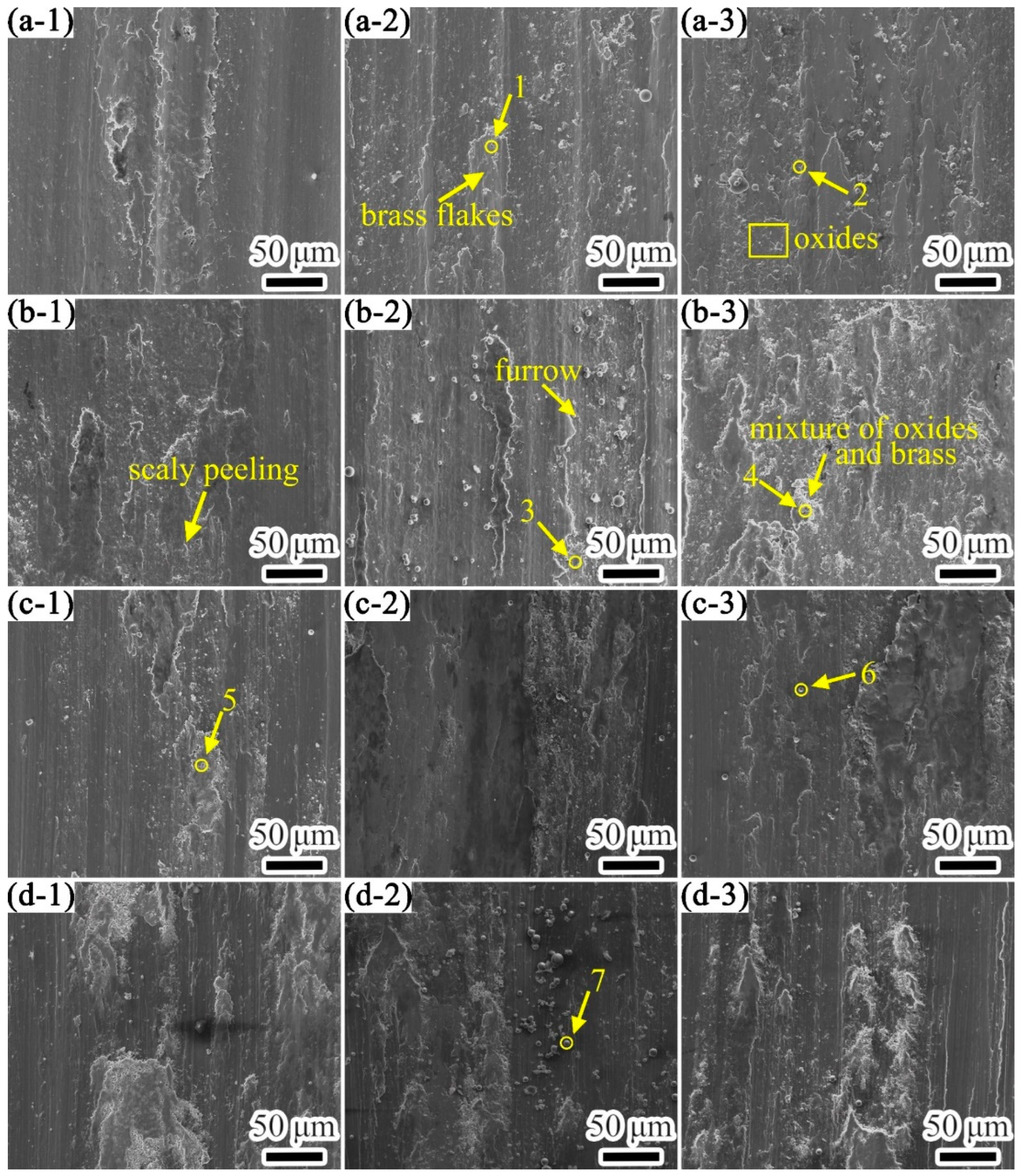
3.3.3. Wear Mechanism of Composite Coating

The wear morphology of the three samples’ wear against H70 brass at different temperatures for 30 min is shown in Figure 13.
At room temperature, the surface of the substrate and the TC4 coating underwent severe plastic deformation and fracture, and the coating peeled off, which caused many wear particles to appear between the surface and the worn ball and caused abrasive wear to occur, resulting in their wear coefficient fluctuating greatly. At the same time, some brass adhered to the wear scar surface under the load. The composite coating only had slight scaly peeling and wear debris.
At 200 °C, the wear debris plowed grooves on the surfaces of the three samples under the action of normal stress. At high temperatures, the material softened, and its shear resistance was low. Meanwhile, because the TC4 titanium alloy material was relatively viscous [31], the wear surface was prone to adhesive force, which made it accessible to adhesive tearing under the action of external force [32]. Adhesive tearing of the composite coating was relatively low.
At 400 °C, the wear debris that accumulated on the surface of the substrate was filled into the furrow, and the furrow became shallow. Large pieces of brass adhered to the surface of the wear scar. The peeling area of the TC4 coating was enlarged, and more alloys were oxidized. Due to the lower strength of TiO2, the oxide film was broken during continuous wear and mixed with the adhered brass to form a large area of adhesive wear. Coupled with the adhesion effect, the two caused the lump debris to become larger at the wear scar. The surface of the composite coating was relatively flat, and the furrow was not obvious. The primary wear mechanism was adhesive wear. Compared with the substrate and the TC4 coating, the adhesive wear of the composite coating was lower. This was because MoS2 had good ductility and was prone to slippage. The formed MoS2 friction film increased the friction contact area [33].
At 600 °C, the furrows on the surface of the wear scar on the substrate became wider, and a lot of brass attached to the surface was broken. It was difficult to observe furrows on the wear scar surface of the TC4 coating. A large amount of brass adhered to the wear scar surface. The main wear mechanisms were adhesive wear and oxidative wear for the substrate and the TC4 coating. The wear morphology of the composite coating was similar to that at 400 °C. For the composite coating, there was less adhesive wear than the substrate and the TC4 coating at 600 °C.
Titanium alloys have high lattice energy at high temperatures and are prone to dislocations and slippage, resulting in plastic deformation. Moreover, alloying elements in TC4 are easily oxidized at high temperatures and produce many oxidation products, such as TiO, TiO2, Al2O3, and V2O3 [34]. Therefore, the wear mechanism at high temperatures is different from that at room temperature. We analyzed the wear mechanism of the composite coating at different temperatures.
The wear morphology of the composite coating wear against H70 brass for 10–30 min at different temperatures is shown in Figure 14, and the EDS detection results of each point in Figure 14 are shown in Table 5. As the wear time increased at room temperature, few scaly and round peak-like peeling layers and oxide abrasive grains gradually appeared on the friction surface [35]. The furrow was shallow, and the peeling was not obvious, but the wear scar surface was attached with large flakes of brass. Therefore, the wear mechanism at room temperature was mainly adhesive wear, accompanied by slight abrasive wear and oxidative wear.
At 200 °C, some shallow furrows and scaly peeling appeared on the surface to which the oxide film and little brass adhered after wearing 10 min. As the wear time increased, the furrow was deepened and a large amount of abrasive debris was produced, and the brass that adhered to the surface was rolled and smoothed. After 30 min of wear, the abrasive grains on the surface disappeared and the mixture of oxides and brass increased. The mixed oxide film had a strong bearing capacity and compactness, which protected the coating and prevented abrasive wear [36]. Therefore, the wear mechanisms at 200 °C were adhesive wear, oxidative wear, and slight abrasive wear.
In the early stage of wear at 400 °C, as the brass was very soft, the furrow on the worn surface was very shallow, and the surface layer did not peel off. The main wear mechanisms were adhesive wear and oxidative wear. As the wear time increased, the adhesive wear increased. However, due to the combined action of the MoS2 transfer film, and MoO3 in the Magnéli phase, the aggravation of the adhesive wear on the coating was delayed. When the wear time increased to 30 min, the coating produced wear debris, which caused secondary wear on the surface, resulting in delamination and furrows. The main wear mechanisms were still adhesive wear and oxidative wear.
At 600 °C, the adhesive wear on the surface of composite coating was severe after 10 min of wear, showing shallow furrows and fine wear debris distributed on it. As the wear time increased, the furrow deepened, and at the same time, the number of abrasive particles increased and an oxide film formed on the wear scar’s surface. The MoO3 with a spherical shape, formed by the oxidation of MoS2, was distributed on the surface. When the wear time increased to 30 min, the abrasive particles decreased, the wear system tended to be stable, and the wear volume increased slightly. The main wear mechanisms were oxidative wear, adhesive wear, and abrasive wear. The high-temperature environment and wear heat caused different degrees of oxidation on the wear contact surface. When the temperature was low, the MoS2 transfer film on the wear contact surface and a small amount of dense Al2O3 oxide film with high load-bearing capacity played a role in reducing adhesive wear. As the temperature increased, the oxidation intensified, which produced a large amount of TiO and TiO2. The oxidation wear occurred, and the loose oxide film reduced the wear resistance of the coating [37]. This resulted in a significant increase in the wear amount of the composite coating at 600 °C.

4. Conclusions

In this study, we prepared a TC4 composite coating reinforced by SiC and MoS2 on a muzzle brake by laser cladding to improve its wear resistance properties and reduce the wear rate. The following results were obtained.
(1) The microstructure of the composite coating was examined. The composite coating consisted of equiaxed grains with grain sizes ranging from 102.39 to 255.31 μm on the surface, and columnar grains with a maximum length of 910 μm and width ranging from 208.78 to 321.81 μm on the bottom. The grains with mesh basket microstructure were mainly α-Ti and β-Ti phases. The strengthening phase SiC with a fine spherical shape was diffusely distributed in the coating.
(2) The microhardness and the shear properties of the composite coating were tested. The microhardness of the composite coating was about 466.75HV, which was almost 1.5 times that of the substrate due to the dispersion strengthening of SiC in the composite coating. Compared with the substrate, the plasticity of the coating, bonding interface, and HAZ increased by 14%, 25%, and 6%, respectively. The fracture mechanism was a brittle intergranular fracture. The high plasticity of the bonding interface indicated that the bonding of the coating is quite strong.
(3) The influence of temperature on wear properties was investigated, and the mechanisms were studied. When wearing against H70 brass, the friction coefficient of the composite coating gradually increased with the increase in temperature. The friction coefficient of the composite coating was about 10% lower, and the wear rate was 15%–35% lower than that of the substrate and TC4 coating when the temperature is below 400 °C. At 600 °C, they were reduced to about 30% and 55%, respectively. Compared with the substrate and TC4 coating, the wear rate of the composite coating was reduced by 15%–35% below 400 °C, and by 55% at 600 °C. The primary wear mechanism of composite coatings at room temperature was adhesive wear. At high temperatures, the main wear mechanisms were adhesive wear, oxidative wear, and slight abrasive wear. Compared with the substrate and the TC4 coating, the dense oxide film and the MoS2 friction transfer film formed on the friction contact surface of the composite coating significantly reduced the degree of adhesive wear. We thus concluded that the composite coating exhibited enhanced anti-friction and wear resistance at high temperatures.

Author Contributions

Methodology, Q.X. and Y.Z.; Project administration, Y.L.; Supervision, H.H.; Validation, Q.X. and X.Y.; Writing—original draft, J.L.; Writing—review & editing, Y.L. and Y.C. All authors have read and agreed to the published version of the manuscript.

Funding

This research received no external funding.

Institutional Review Board Statement

Not applicable.

Informed Consent Statement

Not applicable.

Data Availability Statement

Data is contained within the article.

Conflicts of Interest

The authors declare no conflict of interest.

References

  1. Tchein, G.J.; Jacquin, D.; Aldanondo, E.; Coupard, D.; Gutierrez-Orrantia, E.; Mata, F.G.; Lacoste, E. Analytical modeling of hot behavior of Ti-6Al-4V alloy at large strain. Mater. Des. 2019, 161, 114–123. [Google Scholar] [CrossRef]
  2. Zhang, Z.X.; Qu, S.J.; Feng, A.H.; Shen, J. Achieving grain refinement and enhanced mechanical properties in Ti-6Al-4V alloy produced by multidirectional isothermal forging. Mater. Sci. Eng. A 2017, 692, 127–138. [Google Scholar] [CrossRef]
  3. Kanyane, L.R.; Adesina, O.S.; Popoola, A.P.I.; Farotade, G.A.; Malatji, N. Microstructural evolution and corrosion properties of laser clad Ti-Ni on titanium alloy (Ti6Al4V). Procedia Manuf. 2019, 35, 1267–1272. [Google Scholar] [CrossRef]
  4. Fei, W.; Chuanzhong, C.; Huijun, Y. Research status of laser cladding on titanium and its alloys: A review. Mater. Des. 2014, 58, 412–425. [Google Scholar]
  5. Adebiyi, D.I.; Popoola, A.P.I.; Pityana, S.L. Phase constituents and microhardness of laser alloyed Ti-6Al-4 V alloy. J. Laser Appl. 2015, 27, S29104. [Google Scholar] [CrossRef]
  6. Kim, T.S.; Park, Y.G.; Wey, M.Y. Characterization of Ti-6Al-4V alloy modified by plasma carburizing process. Mater. Sci. Eng. A 2003, 361, 275–280. [Google Scholar] [CrossRef]
  7. El-Hossary, F.M.; Negm, N.Z.; Khalil, S.M.; Raaif, M. Surface modification of titanium by radio frequency plasma nitriding. Thin Solid Films 2006, 497, 196–202. [Google Scholar] [CrossRef]
  8. Costa, M.Y.P.; Venditti, M.L.R.; Cioffi, M.O.H. Fatigue behavior of PVD coated Ti-6Al-4V alloy. Int. J. Fatigue 2011, 33, 759–765. [Google Scholar] [CrossRef] [Green Version]
  9. Veronica, M.C.; Aguiara, C.; Vazquez, A.M.; Robin, A.L.M.; Barboza, M.J.R. Corrosion Behavior Analysis of Plasma-assited PVD Coated Ti-6Al-4V alloy in 2 M NaOH Solution. Mater. Res. 2017, 20, 436–444. [Google Scholar]
  10. Watanabe, I.; Mcbride, M.; Newton, P.; Kurtz, K.S. Laser surface treatment to improve mechanical properties of cast titanium. Dent. Mater. 2009, 25, 629–633. [Google Scholar] [CrossRef]
  11. Jeyaprakash, N.; Chehua, Y.; Tseng, S.P. Characterization and tribological evaluation of NiCrMoNb and NiCrBSiC laser cladding on near-α titanium alloy. Int. J. Adv. Manuf. Technol. 2020, 106, 2347–2361. [Google Scholar] [CrossRef]
  12. Zhang, Y.L.; Li, J.; Zhang, Y.Y.; Kang, D.N. Evolution in microstructure and high-temperature oxidation behaviors of the laser-cladding coatings with the Si addition contents. J. Alloys Compd. 2020, 827, 154131. [Google Scholar] [CrossRef]
  13. Maswuma, Z.; Popoola, A.P. The effect of process parameters on the hardness and wear resistance performance of laser cladded Ti-Si coatings on Ti-6Al-4V alloy. Int. J. Microstr. Mater. Prop. 2019, 14, 1–13. [Google Scholar] [CrossRef]
  14. Ilawe Niranjan, V.; Zimmerman Jonathan, A.; Wong Bryan, M. Breaking Badly: DFT-D2 Gives Sizeable Errors for Tensile Strengths in Palladium-Hydride Solids. J. Chem. Theory Comput. 2015, 11, 5426–5435. [Google Scholar] [CrossRef] [PubMed]
  15. Umeno, Y.; Kubo, A.; Nagao, S. Density functional theory calculation of ideal strength of SiC and GaN: Effect of multi-axial stress. Comput. Mater. Sci. 2015, 109, 105–110. [Google Scholar] [CrossRef]
  16. Anand, M.M.; Shambhu, K.; Parida, S.K.; Das, A.K. Evaluation of hardness and wear behavior of laser cladding zirconia-alumina-titania ceramic top coating on pure Ti6Al4V. Mater. Today Proc. 2020, 26, 1103–1107. [Google Scholar]
  17. Yitian, Z.; Mingyuan, L.; Zhiqi, F.; McCormick, P.; Tan, Q.; Mo, N.; Huang, H. Microstructures and mechanical properties of wear-resistant titanium oxide coatings deposited on Ti-6Al-4V alloy using laser cladding. J. Eur. Ceram. Soc. 2020, 40, 798–810. [Google Scholar]
  18. Li, C.; Zeng, M.; Liu, C.; Wang, F.; Guo, F.; Wang, J.; Yang, Y.; Li, W.; Wang, Y. Microstructure and tribological behavior of laser cladding TiAlSi composite coatings reinforced by alumina-titania ceramics on Ti-6Al-4V alloys. Mater. Chem. Phys. 2020, 240, 122271. [Google Scholar] [CrossRef]
  19. Liu, X.-B.; Zheng, C.; Liu, Y.-F.; Fan, J.-W.; Yang, M.-S.; He, X.-M.; Wang, M.-D.; Yang, H.-B.; Qi, L.-H. A comparative study of laser cladding high temperature wear-resistant composite coating with the addition of self-lubricating WS2 and WS2/(Ni-P) encapsulation. J. Mater. Process. Technol. 2013, 213, 51–58. [Google Scholar] [CrossRef]
  20. Gao, Q.; Yan, H.; Qin, Y.; Zhang, P.; Chen, Z.; Guo, J.; Yu, Z. Self-lubricating Wear Resistant Composite Coating Ti-Ni+TiN+MoS2/TiS Prepared on Ti-6Al-4V Alloy by Laser Cladding. Chin. J. Mater. Res. 2018, 32, 921–928. [Google Scholar]
  21. Dai, J.; Li, S.; Zhang, H. Microstructure and wear properties of self-lubricating TiB2-TiCxNy ceramic coatings on Ti-6Al-4V alloy fabricated by laser surface alloying. Surf. Coat. Technol. 2019, 369, 269–279. [Google Scholar] [CrossRef]
  22. Gao, Q.; Yan, H.; Qin, Y.; Zhang, P.; Guo, J.; Chen, Z.; Yu, Z. Laser cladding Ti-Ni/TiN/TiW+TiS/WS2 self-lubricating wear resistant composite coating on Ti-6Al-4V alloy. Opt. Laser Technol. 2019, 113, 182–191. [Google Scholar] [CrossRef]
  23. Zhu, Y.; Liu, X.-B.; Liu, Y.-F.; Wang, G.; Wang, Y.; Meng, Y.; Liang, J. Development and characterization of Co-Cu/Ti3SiC2 self-lubricating wear resistant composite coatings on Ti6Al4V alloy by laser cladding. Surf. Coat. Technol. 2021, 424, 127664. [Google Scholar] [CrossRef]
  24. Wang, K.; Du, D.; Liu, G.; Pu, Z.; Chang, B.; Ju, J. A study on the additive manufacturing of a high chromium Nickel-based superalloy by extreme high-speed laser metal deposition. Opt. Laser Technol. 2021, 133, 182–191. [Google Scholar] [CrossRef]
  25. Zhu, Z. Research and Development of New-Brand Titanium Alloys of High Performance for Aeronautical Applicaions; Aviation Industry Press: Beijing, China, 2013. [Google Scholar]
  26. Xiyan, Z.; Yongqing, Z.; Chenguang, B. Titanium Alloys and Applications; Chemical Industry Press: Beijing, China, 2005. [Google Scholar]
  27. Zhang, T.G.; Sun, R.L. Microstructure and Properties of TC4 Layers by Laser Cladding on Ti811 Alloy Surface. Trans. Chin. Weld. Inst. 2019, 40, 41–45, 162. [Google Scholar]
  28. Shizhu, W.; Ping, H. Principles of Tribology; Tsinghua University Publishing House Co., Ltd.: Beijing, China, 2008. [Google Scholar]
  29. Ju, H.; Wang, R.; Yu, L.; Xu, J. Influence of Environmental Temperature on the Friction and Wear Properties of Ti-Mo-N Films. J. Jiangsu Univ. Sci. Technol. 2019, 33, 12–17. [Google Scholar]
  30. Ding, Z.X.; Chen, W.; Wang, Q.; Cao, Z.H. Friction and Wear Characteristics of Multimodal WC-12Co Coatings Deposited by HVOF. Tribology 2011, 31, 425–430. [Google Scholar]
  31. Shi, C.X.; Zhong, Q.P.; Li, C.G. China Materials Engineering Canon; Chemical Industry Press: Beijing, China, 2006; Volume 1. [Google Scholar]
  32. Xiaofei, Y.; Faqin, X.; Yong, H.; Guoxian, Z.; Xiangqing, W. Effects of Temperature on Wear Properties and Friction Coefficient of TC4 Alloy. Rare Metal Mater. Eng. 2012, 41, 1463–1466. [Google Scholar]
  33. Zehui, Y.; Nan, W.; Yongnan, C.; Long, Z.; Hong, C.; Jianmin, H.; Wenlong, S. Study on Self-lubricating MoS2/TiO2 Coating Synthesized on TC4 Surface by micro-arc oxidation. Rare Metal Mater. Eng. 2020, 49, 3195–3202. [Google Scholar]
  34. Wang, K.; Du, D.; Liu, G.; Pu, Z.; Chang, B.; Ju, J. High-temperature Oxidation Behaviour of High Chromium Superalloys Additively Manufactured by Conventional or Extreme High-speed Laser Metal Deposition. Corros. Sci. 2020, 176, 108922. [Google Scholar] [CrossRef]
  35. Wanzhen, G.; Zuomin, L.; Xinlei, G. Surface Wear Resistance and Tribological Material Design; Chemical Industry Press: Beijing, China, 2014. [Google Scholar]
  36. Zhang, H.X.; Yu, H.J.; Chen, C.Z. Microstructure and Wear Resistance of Composite Coating by Laser Cladding Al/TiN on Ti-6Al-4V Substrate. Surf. Rev. Lett. 2015, 22, 1550044. [Google Scholar] [CrossRef]
  37. Alam, M.O.; Haseeb, A.S.M.A. Response of Ti-6Al-4V and Ti-24Al-11Nb alloys to dry sliding wear against hardened steel. Tribol. Int. 2002, 35, 357–362. [Google Scholar] [CrossRef]
Figure 1. The morphology of powder: (a,b) TC4; (c,d) SiC; (e,f) nickel-coated MoS2.
Coatings 12 00792 g001
Figure 2. Schematic diagram of laser cladding.
Coatings 12 00792 g002
Figure 3. X-ray diffraction pattern of the composite coating.
Coatings 12 00792 g003
Figure 4. Laser cladding sample: (a) cross-sectional morphology; (b) enlarged area A in (a); (c) microstructure in (b) obtained with SEM.
Coatings 12 00792 g004
Figure 5. Microhardness of the titanium-based composite coating.
Coatings 12 00792 g005
Figure 6. Load–displacement curve of each area.
Coatings 12 00792 g006
Figure 7. Shear strength and indentation rate of each area.
Coatings 12 00792 g007
Figure 8. Shear fracture morphology of composite coating: (a) macro fracture; (b,c) enlarged area A in (a); (d,e) enlarged area B in (a).
Coatings 12 00792 g008
Figure 9. Friction coefficients of three samples’ wear against H70 brass at different temperatures: (a) room temperature; (b) 200 °C; (c) 400 °C; (d) 600 °C.
Coatings 12 00792 g009
Figure 10. The average friction coefficient of three samples’ wear against H70 brass at different temperatures.
Coatings 12 00792 g010
Figure 11. Wear volume of substrate, TC4 coating, and composite coating wear against H70 brass: (a) substrate; (b) TC4 coating; (c) composite coating; (d) comparison of wear for 30 min.
Coatings 12 00792 g011
Figure 12. Wear rate of substrate, TC4 coating, and composite coating wear against H70 brass: (a) substrate; (b) TC4 coating; (c) composite coating; (d) comparison of wear for 30 min.
Coatings 12 00792 g012
Figure 13. The wear morphology of the three types of samples’ wear against H70 brass for 30 min at different temperatures: (a-1) substrate with RT, (a-2) TC4 coating with RT, (a-3) composite coating with RT, (b-1) substrate with 200 °C, (b-2) TC4 coating with 200 °C, (b-3) composite coating with 200 °C, (c-1) substrate with 400 °C, (c-2) TC4 coating with 400 °C, (c-3) composite coating with 400 °C, (d-1) substrate with 600 °C, (d-2) TC4 coating with 600 °C, (d-3) composite coating with 600 °C.
Coatings 12 00792 g013
Figure 14. The morphology of the wear scar of composite coating wear against H70 brass at different temperatures and times: (a-1) RT with 10min, (a-2) RT with 20min, (a-3) RT with 30min, (b-1) 200 °C with 10min, (b-2) 200 °C with 20min, (b-3)200 °C with 30min, (c-1) 400 °C with 10min, (c-2) 400 °C with 20min, (c-3) 400 °C with 30min, (d-1) 600 °C with 10min, (d-2) 600 °C with 20min, (d-3) 600 °C with 30min.
Coatings 12 00792 g014
Table 1. Chemical composition of TC4 substrate and TC4 powder (wt %).
MaterialsAlVFeCNOHTi
Substrate6.304.050.160.0050.0150.170.00388Bal.
Powder5.954.120.100.0120.0120.0840.0032Bal.
Table 2. Optimized process parameter table.
Laser Power (W)Scanning Speed (mm/min)Powder Feeding rate (g/min)Shield Airflow (L/min)Carrier Powder Gas Flow (L/min)Preheating Temperature (°C)Focused Beam Diameter (mm)
150030093582500.2
Table 3. The information of the apparatus used.
Device DesignationCompanyCityCountry
AIM Zeiss microscopeCarl Zeiss AGOberkochenGermany
FEI Nova Nano SEM 400 field emission scanning electron microscopeThermo Fisher ScientificHillsboro, ORUSA
X Pert Pro MPD X-ray diffractometerPANalytical B.V.AlmeloThe Netherlands
DHV-1000ZTEST micro-Vickers hardness testerChengdu Coret Intelligent Technology Co., Ltd.ChengduChina
Micro-shear testerThe Welding Laboratory of Southwest Jiaotong UniversityChengduChina
HT-1000 high-temperature friction and wear testerLanzhou Zhongke Kaihua Technology Development Co., Ltd.LanzhouChina
Bruker Contour GT white light interference three-dimensional profilerBruker CorporationBillerica, MAUSA
Table 4. EDS detection result of the test point in Figure 4c (at %).
ElementAlTiVCSi
Content7.9483.793.033.531.71
Table 5. EDS detection results of each point in Figure 14 (at %).
PointTiAlVMoSiOCuZn
13.150.2016.3649.2831.01
249.912.662.420.350.6442.400.860.76
332.023.761.580.5134.4418.089.61
415.392.030.8855.7416.359.62
525.341.971.370.4148.4816.046.39
618.961.901.0820.620.6056.84
76.731.030.4818.6773.09
Publisher’s Note: MDPI stays neutral with regard to jurisdictional claims in published maps and institutional affiliations.

