1. Introduction
Bearings have already been an indispensable core component in many areas, such as aerospace, high-speed rail, and automotive. In practical application, bearings have been designed to withstand cyclical loads and resist external shocks. The purpose has provided an important guarantee for the high rotational accuracy and high wear resistance of many rotary machines at high speeds. Therefore, the service life and rotation accuracy of all rotating machinery has closely related to these characteristics of bearings. In the manufactured process of bearings, metallurgy, and the preparation of the material, the processing technology of materials, and heat-treatment technology have been the main factors that affected bearing performance [
1]. Among them, the quenching process of the bearing ring has been very important to determine the final strength, wear resistance, rotation accuracy, and rotation noise performance of bearing rings, because the heat-treatment process of the bearing ring resembles close to the last process of bearing parts production [
2,
3].
The heat-treatment process of the bearing ring has been mostly carried out by oil quenching. The heat transfer process on each surface of the parts has been very complicated. After being heated, nucleate boiling occurred in the cooling medium, the vapor film adheres to the surface of the part, and finally, decomposed and boiled [
4]. At the same time, several types of heat transfer have appeared, including latent heat of phase transition. These phenomena caused inelastic thermal deformation during oil quenching.
On the other hand, after the oil is quenched, the bearing ring often produces elliptical deformation, which can cause adverse effects on the rotation accuracy of the bearing. Even if the elliptical deformation has been eliminated by subsequent machining, the surface hardness can be uneven, and the strength and wear resistance of the surface can be decreased. Therefore, the value of ellipticity is one of the important detection indices of the bearing ring after the oil is quenched. However, how does elliptical deformation occur? This question has not been answered, nor verified accurately and reliably.
Simulation has usually been used in the process of heat-treatment analysis to explain the complex phenomena and interactions of multi-field coupling. Professor Inoue and Ju put forward the phase transition mechanics theory and developed heat-treatment simulation software (COSMAP) with a multi-field coupled function, according to the theory [
5]. In recent years, COSMAP has been applied to solve many types of heat-treatment engineering problems [
6,
7,
8,
9,
10,
11]. Xusheng Li et al. simulated a steel gear model based on the measured phase-change plasticity parameters and the metal-thermal-mechanical theory. Transformation plasticity reflects an important distortion behavior of alloy steel materials during the carburizing and quenching heat-treatment process. To reveal the densification behavior and material properties of transformation plasticity, the method proposed for the precise measurement of distortion behavior under rapid cooling is a very effective and practical experimental technique [
12]. Jiangang Wang et al. studied the carburizing and quenching process of helical gear by combining an experiment with a numerical simulation. Based on the theory of metal thermodynamics, they proposed the vapor film located at the outer end surface ruptured preferentially, and the temperature changed dramatically—the position of the inner end face is close to the center, the vapor film is finally broken, and the temperature changes slowly. This temperature difference results in different simultaneity of the microstructure transition, resulting in uneven thermal stress and microstructure stress of the gear. The effect of this stress on the gear is characterized by uneven deformation after quenching [
13]. Li Minglei proposed to reduce the equivalent stress and make the radial deformation more uniform by changing the structure of the outer surface of the outer ring of the bearing research [
14]. Y. Shao, W. Peng, and S. Chen carried out that the cold treatment process can accelerate the transformation from retained austenite to martensite in the bearing ring, reduce the content of retained austenite, refine the martensite structure and promote the precipitation of network carbide, significantly improving the residual stress on the bearing ring surface while reducing the deformation with the cold treatment process added to the heat treatment [
15]. Zhaoxi Cao, etc., explored high carbon bearing steel of GCr15 (100Cr6); double quenching refined both carbides and prior austenite grain sizes and enhanced the RBF-strength and RCF-life [
16]. Xiaohui Lu, etc., optimized the quenching process and added a prior pre-quenching process; the enhanced toughness was attributed to the nanometric martensite-bainite duplex microstructures and the formation of film-like retained austenite [
17]. Kai Zhu, etc., indicate that the medium temperature affects residual stress inside the thick plate significantly during the immersion quenching process; the pre-stretching treatment can effectively reduce residual stresses within the thick plate [
18]. H.Y. Wu, etc., studied a novel spheroidizing annealing treatment, with the increase of the spheroidization degree and the decrease in the cementite particle size in the initial microstructure; the particle size of undissolved carbide decreases, compared with the traditional off-line isothermal spheroidizing annealing, and thus, the properties of the wear and contact fatigue of the samples were improved [
19].
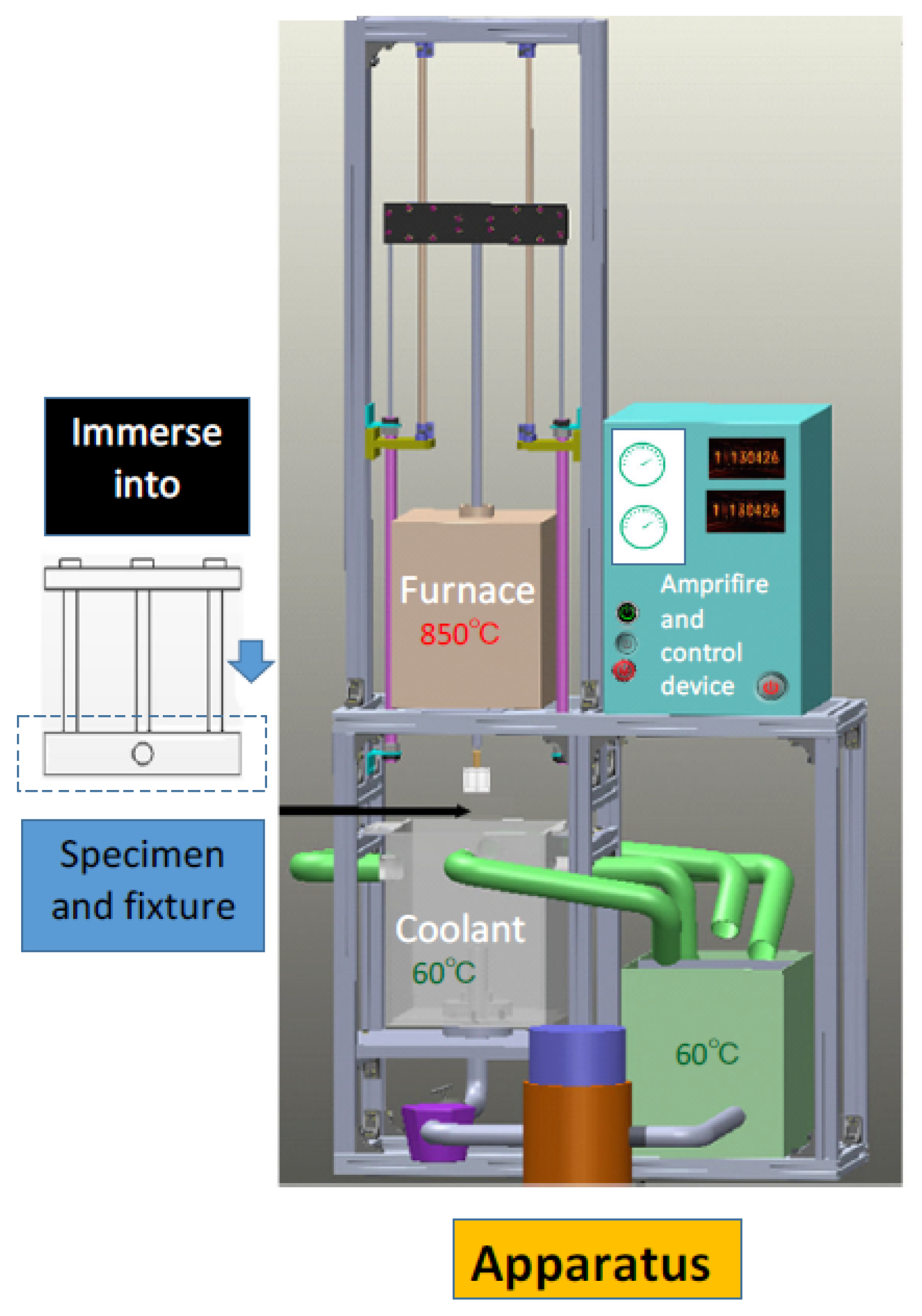
However, up to now, the elliptical deformation of the bearing ring after quenching has rarely been studied and analyzed, especially since the elliptical deformation principle of the bearing ring after quenching has not been reasonably explained. Therefore, in order to explore the elliptical deformation principle of bearing ring quenching, this paper adopted the theory of “metal-heat-mechanics” and the multi-field coupled simulation method to verify the elliptical deformation principle during bearing ring quenching. In particular, it has been found by access to information that the vapor film formed on the outer surface is uneven during bearing ring oil quenching, and the vapor film, which ruptures and boils, is unevenly distributed in the circumferential direction [
4]. The result has aroused concern, and it has been considered that it may be the main cause of the elliptical deformation of the bearing ring. For this reason, several types of heat transfer boundary conditions on the outer surface of bearing rings during oil quenching have been assumed, especially, it has been assumed that when two different heat transfer boundary conditions have been set on the outer surface of the bearing outer ring, in the form of orthogonal symmetry, the purpose is to simulate a non-uniform distribution of the vapor film rupturing and boiling. This is carried out with a multi-field coupled simulation of the bearing ring oil-quenching process. Through the comparison of simulation results and the measurement results of the bearing outer ring ellipse deformation in the experiment, it is verified that the above judgment is the factor leading to the bearing outer ring elliptical deformation. It is often very difficult to determine, however, the heat transfer behavior and heat transfer coefficient of the outer surface of the bearing in this complex set of circumstances. The article proposed the use of inverse analytical and visual analysis methods to obtain the heat transfer coefficients on the surface of steel parts during quenching. Based on the process of oil-film formation and rupture captured by a high-speed camera, three heat transfer models are assumed. Combined with the experimental results, the mechanism of the non-axisymmetric deformation of the bearing outer ring is verified.
3. Results and Discussion
The simulation results of the set axial symmetry heat transfer boundaries are shown in
Figure 8a. It obtained the temperature distribution by axial symmetry heat transfer set during quenched from
Figure 10.
Figure 10a was used to reflect the change of temperature with the time during quenching. The red curve was attained by taking the boundary point at the inner surface of the outer ring; the black curve was taken at the center of the section; the blue curve was taken at the boundary of the outer surface of the outer ring. It can be concluded, therefore, that all the surfaces were set with the same heat transfer coefficient rule and that the cooling rate of the outer circumferential surface and the inner circumferential surface was almost identical. Due to the center of the section had no direct contact with oil or the temperature transfer, which was mainly heated conduction; therefore, its cooling rate was more lower.
From about 5 s to 6 s, the maximum rate occurred, with peaks occurring in this range. As time passed, the decrease in the heat transfer coefficient and effects from the latent heat of the phase transition caused the cooling rate to gradually decrease and level off. As can be seen from the cloud diagram in
Figure 10b, for quenching at 10 s, the temperature difference between the center of the section and the circumferential surface was more obvious due to the small distance of the part cores from the inner and outer surfaces, with a linear spacing of 2 mm. The temperature trend on the inner and outer surfaces was slower than on the top and bottom surfaces of the part.
The effect of this temperature field distribution on deformation is as shown in
Figure 11.
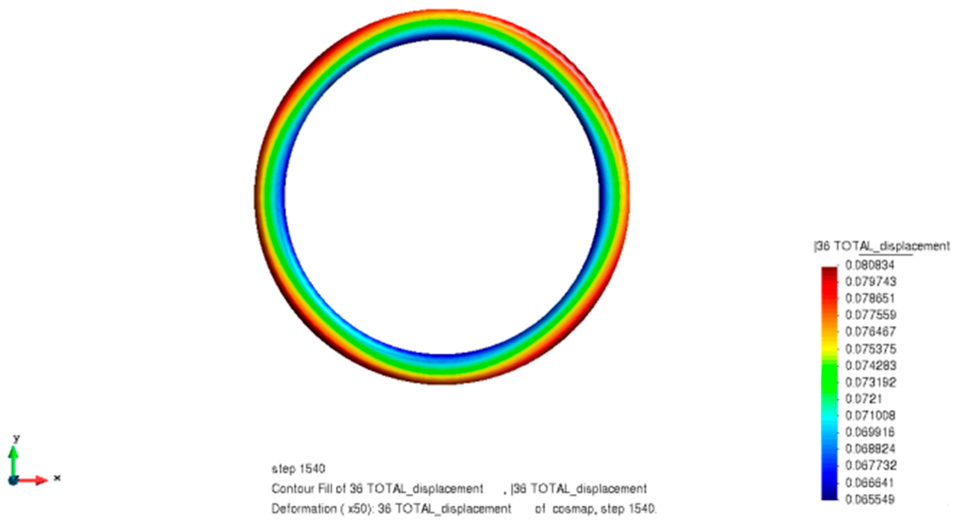
From
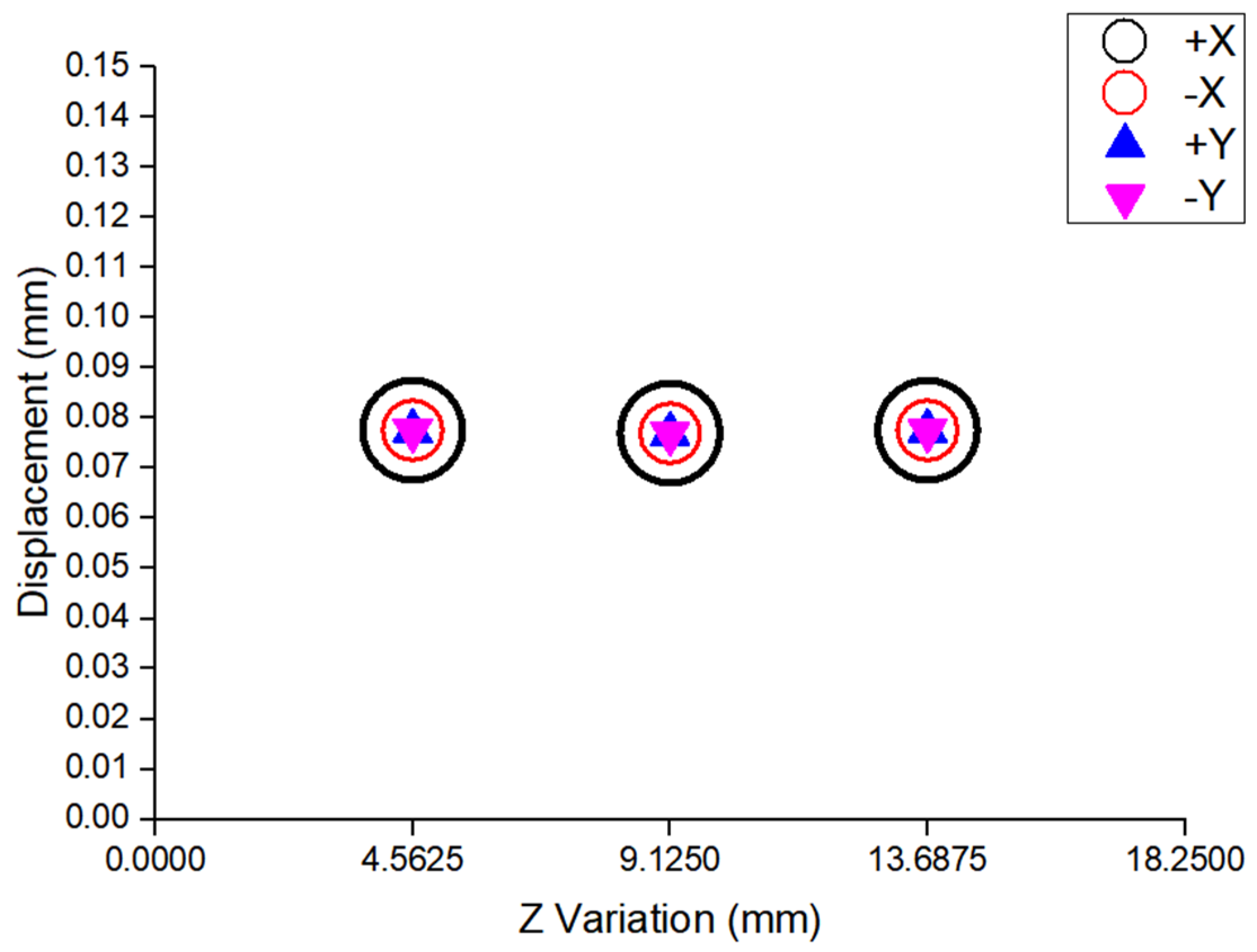
Figure 11, it is obtained that each area of the bearing outer ring deformation was relatively uniform, the deformation trend was close to axial symmetry distribution, and the maximum value was approximately 0.08 mm. When the model was enlarged by 50 times, it still presented a round shape. In order to compare the results with the experiment, we referred to the method of height selection in the ellipticity measurement experiment; four quadrants on the outer surface were measured at different height positions, as shown in
Figure 12. The
X-axis represents the part height position and the
Y-axis represents the deformation value of each quadrant point in different height positions. At any height position, the deformation values of the four quadrant points were almost equal. This proves again, from the result, that there is uniform deformation in the circumferential direction by axial symmetry heat transfer.
Based on the above results, the ellipticity values in different height positions were calculated by axial symmetry heat transfer, as shown in
Table 5. After quenching, the ellipticity values of the bearing outer ring were almost omitted.
It can be concluded, therefore, that all axial symmetry surfaces of the bearing outer ring were applied with the same heat transfer boundary condition; deformation was more uniform and little elliptical deformation after quenching occurred, thus, this is an ideal state. In order to study the causes of elliptical deformation of the bearing outer ring after quenching, the other two different heat transfer boundary forms were applied, as demonstrated in
Figure 8b,c.
Figure 8b represents the orthogonal symmetric heat transfer, which was a typical design, and its analysis results symbolize the surface heat transfer asymmetry in the circumferential direction of all the surfaces during oil quenching. The main step for setting the heat transfer boundaries that the bearing outer ring model was placed under, was the Cartesian coordinate system to divide it into quadrants. In one quadrant, the heat transfer law of the inner and outer surfaces was the same. The value rules of adjacent quadrants are different.
Figure 8c shows the orthogonal symmetric heat transfer on the outer surface and the axial symmetry heat transfer on the inner surface, which was another typical design. Its analysis results symbolize the surface heat transfer asymmetry in the circumferential direction of only one surface (refer to
Figure 8b,c for the boundaries set, the simulated bearing outer ring quenching, and the temperature field and ovalness).
Figure 13a,b reflects the temperature field change with the orthogonal symmetric heat transfer boundaries being set.
Figure 13c,d reflects the temperature field change with the external orthogonal symmetrical and internal axial symmetry heat transfer boundaries being set.
In the coordinate system, by intercepting the bearing outer ring model with a 45-degree line and 135-degree line, the center point of the two geometric sections was taken, the temperature field change at the two points during the quenching process was analyzed, and the temperature cooling curve with time was constructed, as shown in
Figure 13a,c. The upper model in the 45-degree line and 135-degree line area was intercepted, and its temperature distribution is presented in the form of a cloud picture, as shown in
Figure 13b,d.
From
Figure 13a, the green curve has shown the effect on temperature by applying the green heat transfer coefficient rule shown in
Figure 7, while the red curve has indicated the application of the red heat transfer coefficient rule in
Figure 7. As the green curve heat transfer coefficient reaches its peak first and the red slightly later, there is a certain time difference. Therefore, the cooling rate of the green curve was faster than the red one. The maximum rate of the green curve occurred in about 2 to 3 s, with peaks occurring in this range. However, the red curve reached the above details between 5 s and 6 s. Under the different heat transfer conditions, the temperature changed over time, which was already different. Comparing
Figure 10a and
Figure 13a, the rule of the black curve in
Figure 10a and the rule of the red curve in
Figure 13a were in agreement, which leads to the conclusion that under the same heat transfer conditions, the temperature changed with time is already almost the same. In summary, the change in the heat transfer coefficient has affected the change in the temperature field.
The cloud plot in
Figure 13b shows that the heat transfer process in quenching took place firstly in the right half and later in the left half. This result can match the heat transfer law of the two curves in
Figure 7. The temperature gradient in the annular direction was obviously produced, and the temperature distribution boundary and the heat transfer boundary were close to coinciding. This verified that the time difference between the bearing outer ring’s two surfaces of oil-film rupture during the quenching process could create a temperature gradient. Combined with
Figure 10b, heat transfer asymmetry in the circumferential direction on each circumferential surface has caused an uneven temperature distribution in the circumferential direction.
From
Figure 13c, the green curve shows the comprehensive effect on temperature when different heat transfer rules are set on the inner and outer surfaces. The red one has indicated the temperature change under the influence of the red heat transfer coefficient rule in
Figure 7. However, the cooling rate of the green curve was faster than the red one, about 2 to 3 s, where the maximum rate of the green curve occurred, with peaks occurring in this range. The red curve reached the above details between 5 and 6 s, however, the zone area which was formed between the green curve and red curve was smaller in
Figure 13c than in
Figure 13a. The area of the intersecting area of two curves can be mathematically expressed as the integral of the temperature difference at the analysis point in the time range.
The cloud plot in
Figure 13d shows that the heat transfer process in quenching took place firstly in the right half and later in the left half; the temperature gradient in the annular direction was obviously produced. Compared with
Figure 13b, the right half of the model was affected by the heat transfer coefficient of the inner surface, and the heat transfer speed on the inner surface was slower. Combined with the analysis in
Figure 13b,d, as long as there was a circumferential surface with different heat transfer laws, that is, the oil film ruptured was uneven in a certain circumferential direction, it produced a temperature gradient in the annular direction.
Summarizing all the analyses presented in
Figure 13, the presence of the crossover region could indicate the presence of a temperature gradient in the annular direction. When different heat transfer conditions were set on any circumferential surface, it created a temperature gradient in the annular direction. The size of the area may be related to the value of the ellipticity of the outer ring of the bearing after quenching. This needs to be verified in the deformation simulation.
The effect of temperature field distribution on deformation is shown in
Figure 14. The bearing outer ring has occurring non-axisymmetric deformation.
Figure 14 shows a magnified 50× deformation plot after quenching. After quenching, it has deformed to a greater extent in the negative 45-degree direction, and to a lesser extent, in the 45-degree direction, an elliptical form is shown.
Because the annular temperature gradient appeared in quenching, this made it load larger compressive stresses in the negative 45-degree direction and load smaller compressive stresses in the 45-degree direction, just as
Figure 15 shows.
The ellipticity is calculated in 45-degree and negative 45-degree directions. The maximum and minimum deformation in different height directions is shown in
Figure 16 and the ellipticity is calculated, as shown in
Table 6.
Figure 16 shows that the bearing outer ring deformation has a maximum and minimum value in the circumferential direction by different heat transfer boundary conditions, which are applied to different surfaces of the bearing outer ring. It forms the ellipticity in the circumferential direction.
Table 6 shows that with applied orthogonal symmetrical heat transfer, the ellipticity was 0.14 mm, and with applied external orthogonal symmetrical and internal axial symmetry heat transfer, the ellipticity was 0.158 mm. Because the former for the newly added boundary conditions resulted in a residual stress value of about 42 MPa, while the latter, due to the internal surface still maintained axial symmetry, the newly added boundary conditions are only applied to the external surface of the bearing outer ring; therefore, the residual stress value is about 30 MPa. The residual stress value on the circumferential surface is different, causing an ellipse of the bearing outer ring. The analysis of the temperature cooling curves mentions the size of the area where the curves cross as a possible reason for the value of ellipticity, and thus, here it was also confirmed.
Combining
Table 5 with
Table 6, it can be concluded that when all surfaces applied the same heat transfer law, an annular temperature gradient was formed, and the ellipticity results of the simulation are little and almost invisible. However, the surfaces applied with two or more heat transfer boundary conditions created a temperature gradient in the annular direction, and resulted in orthogonal residual thermal stress, leading to form non-axisymmetric deformation, and the bearing outer ring presented an elliptical shape. The ellipticity results of the simulation are closer to the experimental situation in
Table 1. The conclusion shows that the two types of assumed non-axisymmetric cases develop a judgment on the formation mechanism of the elliptic bearing outer ring after quenching. The actual simulation needs to obtain the rule of heat transfer coefficients on each surface of the part before the simulation can produce data consistent with the experimental results.


