Article

Laser Surface Melting and Consecutive Point-Mode Forging Hardening of DH36 Marine Steel: Mechanical and Precipitation Behavior

1
Key Laboratory of Advanced Forging & Stamping Technology and Science, Ministry of Education, Yanshan University, Qinhuangdao 066004, China
2
School of Mechanical and Automobile Engineering, South China University of Technology, Guangzhou 510640, China
*
Authors to whom correspondence should be addressed.
This is the main author.
Coatings 2022, 12(4), 495; https://doi.org/10.3390/coatings12040495
Submission received: 21 February 2022 / Revised: 1 April 2022 / Accepted: 5 April 2022 / Published: 7 April 2022

Abstract

:
This study investigates the effect of the laser surface melting and consecutive point-mode forging process (LSM-CPF) on the mechanical properties and the microstructure of DH36 marine steel. The microstructual revolution during the LSM-CPF process are revealed by metallographic microscope (OM) and scanning electron microscope (SEM) technique, and the strengthening mechanisms for different samples are also elucidated. The results show that the best yield strength (σ0.2) and tensile strength (σb) for the sample treated with 4000 W laser power and 10% reduction ratio are 721.3 and 884.2 MPa, which are 49.55% and 41.54% higher than that of the DH36 matrix, respectively. The hardness of the coatings decreases along the normal direction with the maximum value of 586.4 HV in the CPF zone for the sample treated with 2000 W laser power and 20% reduction ratio. During the low power LSM-CPF treatment, the nanoscale cementite appear as intragranular due to the inhibited carbon diffusion. The coherent boundary of (110)NbC‖(110)Ferrite, [1 1 ¯ 0]NbC‖[001]Ferrite between NbC and ferrite reduces the nucleation barrier to promote the nucleation of acicular ferrite (AF). The strengthening mechanism for samples treated at 2000 W is found to be dislocation strengthening. During high power laser treatment, pearlite transformation is found to occur with a low cooling rate. In this case, the strengthening mechanism is the boundary strengthening of lamellar pearlite and dislocation strengthening.

1. Introduction

High-strength low-alloy steel is widely used as a structural component in the marine engineering industry, particularly in the construction of vessels, submarines and offshore drilling platforms [1,2]. DH36 marine steel is mainly used in the fabrication of vessel shells owing to its prominent mechanical properties, weldability and corrosion resistance. Compared to an enormous hull structure, the ratio of the vessel shell thickness to the total vessel volume is extremely small. Therefore, the hull surface is prone to be destructed in harsh working conditions, such as a dramatic impact with a towboat or with a crash pad on the dock during arrival in the harbor which requires the superior surface mechanical properties of DH36 marine steel.
Laser refabrication is a type of green and efficient reconstruction technology [3]. In previous studies, researchers mostly used laser cladding to produce functional or protective surface coatings to improve the matrix properties under complicated service conditions. He et al. [4,5] produced Al-Ni-TiC-CeO2 composite coatings on the surface of S355 offshore steel by laser cladding. When soaked in 3.5% NaCl solution, Al2O3 and AlOOH precipitated in the coating and effectively hindered further corrosion expansion. Li et al. [6] deposited SUS308L on low carbon steel by laser hot wire cladding (LHWC). They reported that the highest value of hardness increased by 24% reaching 196 kgf/mm2 in the heat-affected zone and the elongation of the cladding layer was found to be 44.8%, which is twice that of the DK 40 matrix. However, there are two major issues with the laser cladding process which are the dilution rate defined as the intermixing ratio of the coating with the base material [7] and the thermodynamic cracks induced by the different solidification speeds of molten powder and the substrate in the laser cladding process. The laser surface melting process significantly reduces the dilution rate which (signifies the similarity in the properties of the clad coating and substrate material) to realize tight metallurgical bonding and avoids surface thermodynamic cracks without extra additional compounds. Khorram [8] et al. treated AISI 431 stainless steel to improve the surface hardness. The surface hardness was found to increase up 650 Hv (80% higher than that of the base metal) due to martensitic transformation by the Nd:YAG laser under the rapid cooling rate.
Nevertheless, it is widely accepted that grain refinement results in excellent performance [9]. At present, the physical method of grain refinement mainly includes the deformation process, physical (electric or magnetic) field, rapid cooling and mechanical vibration method. Wang et al. [10] proposed the ultrafast cooling (UFC) method after final rolling to realize refined degenerate pearlite with nanoscale cementite precipitations for the 300 MPa yield strength advancement of 0.17 C carbon steel. Dekhtyar [11] investigated the microstructure revolution and fatigue behavior of powder metallurgy Ti6Al4V alloy on applying ultrasonic impact treatment (UIT) which suggested that fatigue strength enhanced by up to 60% as a consequence of the increased dislocation density, essentially refined α + β microstructure and with randomization in the orientation of α -grains. However, considering the razor-thin strengthening layers of UIT, which are usually 40–60 μm, this method lacks applicability in actual manufacturing.
In this work, we used consecutive point-mode forging (CPF) to further strengthen the coatings treated by the laser surface melting (LSM) process which combined the character of rapid cooling rate from LSM process and plastic deformation from CPF process to manufacture valuable surfaces for practical application. The microstructure and the mechanical properties of the coatings were investigated by OM, tensile and hardness tests. The effect of correlating precipitation behavior in LSM and CPF process was illustrated by TEM techniques.

2. Experimental Procedure

The LSM-CPF in-house system mainly consists of 5000 W fiber optic laser (RFL-A5000D, Raycus, Wuhan, China), CNC-controlled four-axis working platform and a cold forger with a forging ram of 3 mm diameter. Moreover, an argon (99.99%) purged chamber with oxygen content less than 8 × 10⁻⁶ was used to prevent the molten pool from oxidation (Tecsense Tecpen Fibre, Grambach, Austria). A brief schematic of the LSM-CPF process is shown in Figure 1, in which the laser surface melting coatings were further deformation-strengthened by consecutive point-mode forging process. There are a lot of factors that significantly influence the ultimate mechanical properties of laser surface melting coatings, such as laser power, scanning velocity, laser beam diameter and overlapping ratio. The subsequent CPF process is susceptible to the reduction distance and the overlapping ratio of two forging points. The detailed process parameters are shown in Table 1; meanwhile, the laser beam diameter is 3 mm, the focal length is 140 mm, both the overlapping ratios in the LSM and the CPF process are 50% and the defocus distance is +5 mm. According to the Prandtl slip-line field of semi-infinite height blank established by the stress boundary conditions, the depth of the plastic deformation zone on the surface is half of the width of forging ram, i.e., 1.5 mm considering their geometrical relationship. As a result, the reduction ratio (ε) is 10% and 20% for different samples [12,13].
The nominal composition of DH36 steel, in this work, was 0.054 C, 1.42 Mn, 0.25 Si, 0.05 Nb, 0.042 V, 0.042 Cr, 0.036 Al, 0.025 Mo and 0.02 Ti with balance Fe (wt%). After being ground by SiC papers ranging from 800 # to 3000 # and etched with 4 vol% picric acid alcohol, the microstructures of cubic samples were observed under a metallographic microscope (OM, Zeiss AX10, Oberkochen, Germany) and scanning electron microscope (SEM, Zeiss 500, Oberkochen, Germany) by electricity discharged along z direction. The yield strength, ultimate tensile strength (UTS), elongation and Vickers hardness (200 g load) is 483 MPa, 574 MPa, 21% and 182 HV, respectively. The precipitation behaviors of samples were imaged by transmission electron microscope (TEM, FEI 200, Hillsboro, OR, USA) where the films of TEM were mechanically thinned to approximately 50 μm and further electrochemically jet polished at −30 °C in 15 vol% perchloric acid in ethyl alcohol solution (Struers tenupol 5, Cleveland, OH, USA).
In order to manifest the variation of mechanical properties of the LSM-CPF coatings, uniaxial tension experiments (Zwick Z010, Augsburg, Germany) were conducted to test the yield strength, and the tensile strength with the strain rate at 0.005 min−1 at room temperature (20 °C) as ASTM E8-2016 for both of LSM and LSM-CPF coatings, which the geometric size of tensile specimen is shown in Figure 2b. The morphology of tensile fractures was observed under SEM. The hardness of the samples was measured by an automatic Vickers hardness test machine (Qness 200, Salzburg, Austria) with a load of 200 g and a retention time of 20 s to explore the hardness distributions from the CPF zone to the substrate which separated 0.2 mm as ASTM E92-2017. The detailed mechanical test approaches for LSM-CPF process treated samples are shown in Figure 2a.

3. Results and Discussions

3.1. Microstructure Revolution

The microstructure mainly contains ferrite (F) and pealite (P) for DH36 marine steel, in which which the pearlite stands in bands surrounding the ferrite, as shown in Figure 2d. The macrostructure is shown in Figure 3, where three aspects for LSM process treatment samples can be easily recognized; these are remelted zone (RZ), heat-affected zone (HAZ) and base material. Nevertheless, different from the macrostructure, there obviously is an extra CPF zone at the top of the RZ for sample 3, as illustrated in Figure 2c. It manifests that the depth of the coating increases when the laser power is enlarged, which is 1.04 mm and 1.41 mm for sample 1 and sample 2, respectively, both measured by Image J software. In addition, as noted in previous research, it obtains a higher temperature gradient and lower cooling rate when increasing both the laser power and scanning speed for sample 2 [14].
As shown in Figure 4, the microstructure of RZ is somewhat different along the z axis for LSM process treatment samples. It is considered that both the temperature gradient and cooling rate decrease from the bottom of molten pool to the top of the coating along the z axis. AF structures appear near the solidus–liquidus boundary owing to the rapid cooling rate at the bottom of molten pool. When DH36 marine steel travels the solidification of LSM process, the low elements, such as Ti, Al and Si, are prone to merge as spherical precipitations to provide nucleation sites for AF structures which are surrounded as scattering state. In the middle of the RZ of sample 1, the PF transformed to GBF which coarse with enough incubation time to as the low energy state as a result of the declined cooling rate. Kinetic driven by high temperature gradient for LSM process, there are small size of precipitations shown in GBF. In the top of the RZ, the size of precipitations obviously enlarges with more sufficient incubation time according to Ostwald ripen theory. As for sample 2, the microstructure consists of GBF and P with numerous precipitations because of a higher temperature gradient compared with sample 1. Owing to a lower cooling rate, the mean grain size significantly enhanced. From the bottom to the top of RZ, the content of pearlite also increases resulting from a lower cooling rate along the z axis. In general, the LSM process could transform the construction and distribution of the microstructure and decrease the mean grain size of DH36 marine steel which further improves the mechanical properties of the coatings.
After CPF deformation, which induces dislocation density propagation and interaction, a large number of dislocations accumulate and intertwine suggesting the appearance of recrystallization which results in refined ferrite separated into tiny PF of high energy state. Shown in Figure 5b, the PF coarse under a higher reduction ratio (ε). Similar to the low power treatment samples, there also are PF interconnected each other shown in CPF zone indicating superior mechanical properties. It is considered that the recrystallization process is almost complete with the reduction distance of 0.3 mm which uniformly contains polygonal ferrite and pearlite in the CPF zone of sample 6.

3.2. Mechanical Properties

3.2.1. Tensile Properties

The tensile property of LSM and LSM-CPF process treatment samples were tested and the tensile curves and relevant data are shown in Figure 6 and Figure 7. It is considered that the LSM process could improve the yield strength (σ0.2), UTS (σb) and elongation for the remelted zone of DH36 marine steel. When increasing the laser power, the σb and elongation exhibit a hike compared with low laser power treatment sample which ultimately raised by 15.35% and 11.90%, but the σ0.2 slightly decreased for sample 2. As for residual samples, it is observed that LSM-CPF process could significantly induce the yield strength and tensile strength and, at the same time, the elongation shows a decline as the surface of the coating under severe plastic deformation according to previous research. Both σ0.2 and UTS enhance when increasing the reduction ratio as the most outstanding mechanical property of sample 6 for 4000 W laser power treatment and 20% reduction ratio with 677.8 MPa and 862.8 MPa, which is superior 40.33% and 50.31% for DH36 substrate, respectively. As for the elongation, it decreased to nearly 16% after the LSM-CPF process.

3.2.2. Fracture Morphology

The fracture morphologies of LSM process-treated sample are shown in Figure 8. It is observed that the section of fracture macrostructure is relatively flat, indicating the poor plasticity after the LSM process. Revealed by Section 3.2, the composition of microstructure for sample 1 is different along the z axis. Thus, there are large amounts of terraces and cleavages, which is considered a mixed ductile and brittle fracture mode for sample 1, as shown in Figure 8b. However, the microstructure of sample 2 is fairly uniform and the fracture morphology consists of tiny dimples for sample 2, suggesting the fracture mode is the ductile fracture.
The fracture morphology of LSM-CPF process-treated samples with different reduction ratios are shown in Figure 9 and Figure 10, respectively. Compared to the single LSM process-treated samples, there are obviously separated layers between CPF and LSM zones where the CPF zone is a compact layer with the appearance of prior austenite grain boundary (PAGBs) and surrounded by terraces in the LSM zone, suggesting the occurrence of severe plastic deformations during in tensile process, shown in Figure 9b,f. The content and size of PAGBs of the 2000 W treatment sample are much greater than that of the 4000 W treatment samples. In addition, a large size of precipitation is shown in the RZ due to sufficient kinetics provided to the low alloy elements to diffuse out of the grains by the high temperature gradient and adequate incubation time by low cooling rate as Figure 9g. What is more, according to the Griffith crack extension theory, the small size precipitations as the brittle phase promote crack initiation, which results in a better yield strength for sample 5 compared to sample 3 at the same reduction ratio. Moreover, considering the microstructure of CPF zone in Figure 5, interlaced polygonal ferrite boundaries effectively enhance deformation resistance in uniaxial tensile test. With the increase in the reduction ratio, the fracture morphology tends to be uniform. For the CPF zone, which is mainly shown as dimples, the average size of dimples of high-power laser treatment samples were coarse, suggesting prior tensile properties when compared to low-power laser treatment samples. From the view of energy, the CPF process induces numerous dislocations into the coatings of DH36 marine steel. Thus, it should firstly consume these parts of extra defects in tensile process which exhibits superior yield strength for LSM-CPF process treated samples. Generally, it is considered ductile fracture mode for the LSM-CPF treatment samples under tensile tests.

3.2.3. Hardness Distribution

As shown in Figure 11a, hardness of the CPF zone along y axis is observed owing to the minor reduction distance. It is considered that the value of average hardness in the CPF zone for samples with a high reduction ratio is higher than that of samples with a low reduction ratio. In 2000 W treatment samples, the hardness of their CPF zone enhances by numerous AF structures. Owing to higher amounts of coarse GBF as the structure softens, the hardness slightly decreases for 4000 W treatment samples. Meanwhile, shown in Figure 8b, the hardness gradually declines from the CPF zone to the DH36 base material and the LSM process could improve surface hardness for DH36 marine steel. The average hardness increases 31.55% and 25.84% for different laser power surface melting process. As for the CPF process, sample 4 shows the best surface hardness of 586.4 HV which increases 77.24%, 115.59%, 48.76% and 71.42% in the CPF zone for different samples compared to base material, respectively. Overall, the LSM-CPF process could further promote the surface hardness for DH36 substrate.

3.3. Precipitation Behavior

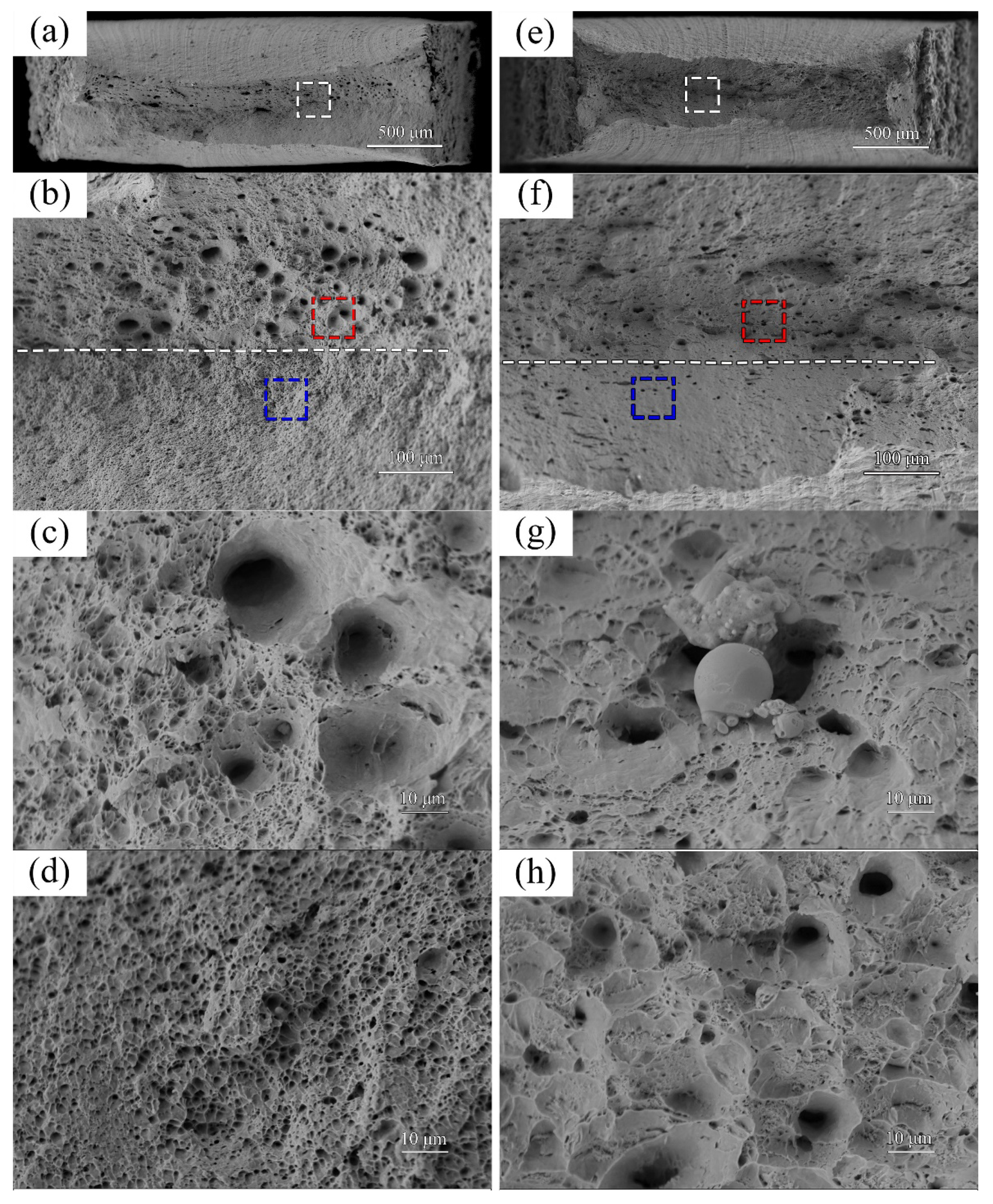
The morphologies of precipitations for LSM-treated samples are shown in Figure 12 and 
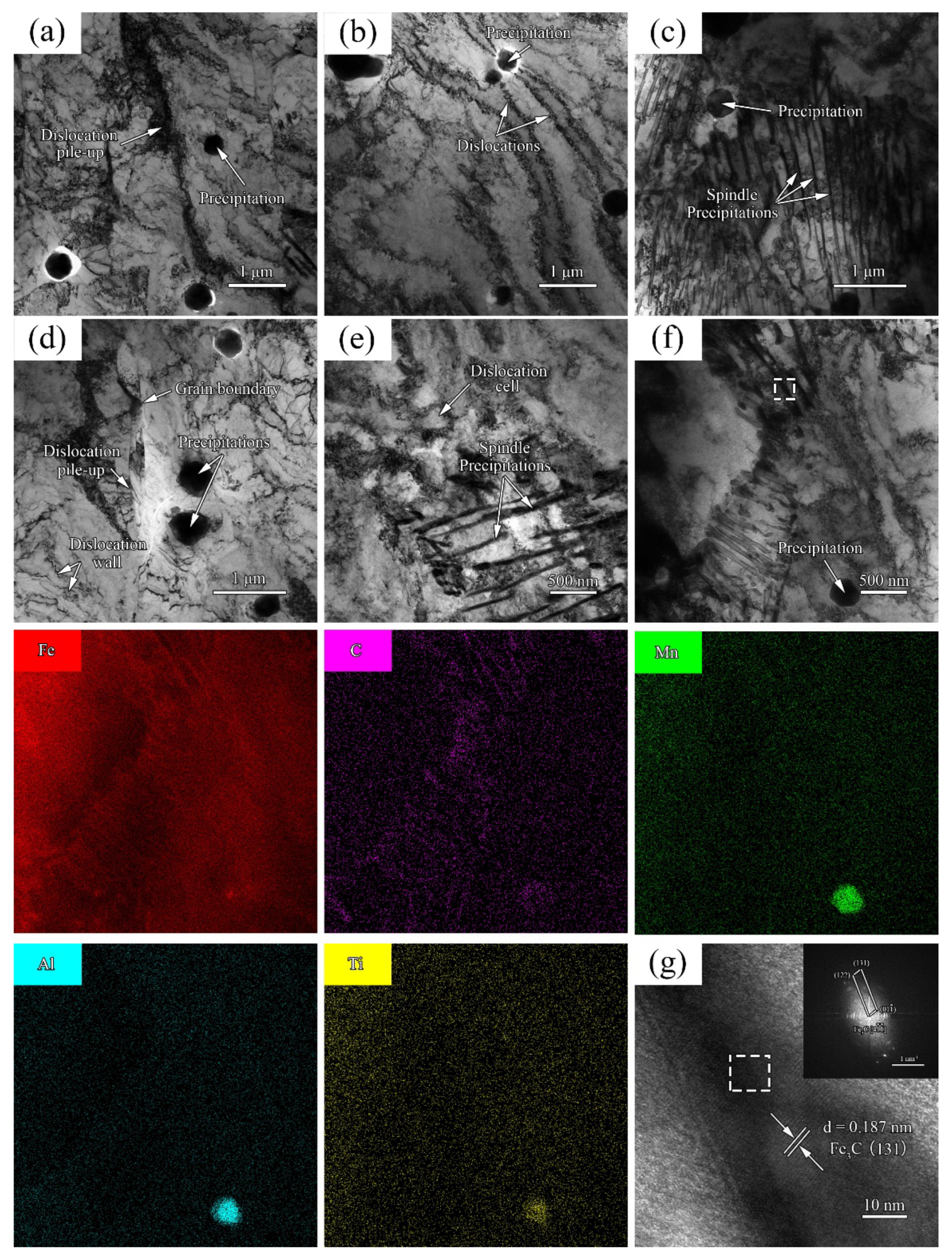
Figure 13, respectively. There are irregular spherical precipitations with the average size of 150 nm shown in the RZ of sample 1, which could be recognized as elliptical cementite according to the distribution of elements detected by EDS. However, as shown in Figure 13, large spherical precipitations, nearly 500 nm, and spindle-like precipitations can be observed in sample 2. As the further mapping image of the spherical precipitations, it is implied to be due to the Mn-Al-Ti oxide precipitations. Furthermore, the spindle-like precipitations are determined as the Fe3C [10 2 ¯ ] precipitations by the high-resolution transmission electron microscopy (HRTEM) images and the corresponding fast Fourier transform (FFT) patterns, where the lattice distance of the precipitation is measured as 0.211 nm via Image J software (ICDD PDF #65-2412). In the process of LSM, the Fe element and micro-alloy elements of DH36, such as Mn, Al and Ti, inevitably undergo oxidation reactions to form multiple oxides. The diffusion kinetics of the iron atom are much higher than that of micro-alloy elements. Hence, the intragranular precipitations mainly consist of the micro-alloy elements rather than Fe element. The carbon atoms are hindered to diffuse at extremely high value of G, revealed in Section 3.1, but it provided sufficient diffusion kinetics for micro-alloy elements. Thus, the Fe element and micro-alloy elements of DH36, such as Mn, Al, and Ti, inevitably undergo oxidation reactions to form multiple oxides in the LSM process. Furthermore, micro-alloy atoms merge r as spherical compounds according to Ostwald ripening theory to reduce the entropy of the whole system. Owing to the bare carbon content of DH36 marine steel, a proeutectoid reaction occurred to produce ferrite when the temperature of Ar3 was lower in the solidification process. Moreover, carbon atoms have difficulty in getting rid of ferrite and enrich as irregular spherical precipitations without enough coarse time. With a lower cooling rate, the cementite grow as a spindle-like state in adequate incubation time for sample 2.
In order to elucidate the strength mechanisms of the LSM-CPF process, TEM images are also were observed which numerous dislocations pile up at the grain boundary in sample 3, as Figure 14a. What is more, there are intragranular spherical precipitations shown in the CPF zone, and dislocations hardly cut through and bypass these precipitations to bend and leave extra stress as Orowan dislocation rings in the plastic deforming process. In the process of CPF, dislocations propagate and tangle together as a dislocation cell which subsequently migrates and portions of this cell are absorbed by the grain boundary in Figure 14c. For the high reduction ratio of sample 4, the dislocation density increases significantly. As can be seen in the figure, there is a large number of precipitations surrounded by a high density of dislocations with an average size of about 400 nm and spindle-shaped tiny precipitations dispersed in the grain boundary resulting in dispersion strengthening. From ICDD PDF #65-7964 and PDF #06-0696, the appearance of NbC precipitation with the coherent boundary of (110)NbC‖(110)Ferrite, [1 1 ¯ 0]NbC‖[001]Ferrite between NbC and ferrite is considered. As a nucleation position, the NbC precipitation promotes the formation of AF. AF needs high energy for the microcrack step or excursion with its interlocking structure, and thus has superior mechanical properties.
With the increase of strain (ε), the refined grains exhibit a lamellar structure with the pile-up of dislocations at the grain boundary. According to the Frank–Read source dislocation multiplication mechanism, the dislocations slide to the precipitations to constantly release dislocation loops because of the shear stress under the CPF process, which ultimately wraps the precipitation in the form of the dislocation cell, as shown in Figure 14f. As the forging ram was applied on the coatings of DH36 marine steel, the RZ zone underwent triaxial compressive stress in the CPF process where the precipitations exhibit parallel arrangement with a decrease in the distance between the precipitations. In the tensile process, dislocations are multiplied and piled up at the grain boundary with part of the grain torsion favorable to the orientation for deformation, which partly reduces the mechanical properties when compared with sample 1. Moreover, numerous dislocations tangle around spherical precipitations and pinned by spindle-like cementite restrain crack promotion in the tensile process. Generally, this could be considered as second phase strengthening and dislocations strengthening induced by the CPF process for 2000 W treatment samples.
At the initial stage of plastic deformation, dislocations slide to encounter the gross precipitations, which is the source of the torsion and tangle. As the plastic deformation proceeds, the torsion of blocked dislocations intensifies until both ends of the dislocations meet and counteract which subsequently move to the grain boundary, as shown as Figure 15b. According to the HRTEM and corresponding FFT images in Figure 15f, the spindle-like precipitations could be determined as cementite which reveals that, a diffusion-controlled phase transition, pearlite transformation occurred in the 4000 W-treated LSM process. The super-cooled austenite simultaneously precipitates the pearlite structure composed of eutectoid ferrite and cementite at Ar1 (the beginning temperature of austenite to pearlite transformation) during the high-power laser LSM-CPF process to enhance the strength and toughness for sample 5. The lamellar pearlite could be further recognized as sorbites considering their minor average interlamellar spacing (ILS). In the phase transformation of the cooling process, Fe and carbon atoms produce long distance diffusion, which consumes the energy in a high temperature gradient provided by a high-power laser. Moreover, pearlite tends to nucleate at grain boundaries and micro-defects as dislocations. In contrast, the refined austenite grains with an increase in the area of grain boundary for LSM treatment samples have multiple nucleation locations and also promote pearlite transformation. In previous research, it was pointed out that a low cooling rate for 4000 W treatment samples could lead to the formation of obviously lamellar structures. The low-alloy elements, such as Ti in DH36 marine steel, improve the carbon element activity to promote carbon diffusion away from the enrich region of these low-alloy elements, which nucleate intragranular ferrite at a low cooling rate. When a large number of ferrite nucleate and connect as a plane at the high transformation temperature region of Ar3, the excess carbon elements will be exclusive to the low transformation temperature region, which requires long migration distance for ferrite growth interface and austenite contact interface (α-γ interface), which eventually forms as lamellar pearlite according to the GKLP theory proposed by Grossterlinden [15]. However, the enriched carbon elements in front of the border scatter as nanoscale cementite in grains rather than migrate with an instant period of time at high cooling rate. The block-shaped ferrite tend to connect and grow forward as a two-dimensional plane which facilitates carbon diffusion and intergranular nucleation to form pearlite. Additionally, as seen in the microstructure observed in Figure 4a, there are numerous AF structures without proper diffusion direction, in which the carbon atoms diffuse perpendicular to the acicular ferrite growth direction. This is another reason for the non-existence of lamellar pearlite in low power treatment samples. In Figure 15d, when increasing the strain, dislocation cells continuously propagate until it reaches the grain boundary with high reduction ratio according to the Frank-read dislocation mechanism, which induces hardening effect to enhance hardness. Meanwhile, the ILS between ferrite and cementite exhibits decreasing at higher reduction ratio. What is more, it also can be seen that no extra spherical precipitations appear to chop up spindle cementite which is another reason leading to prior tensile property for sample 6. Overall, it could be recognized as boundary strengthening, second-phase strengthening induced by dislocation ring, and dislocation strengthening during the high-power laser LSM-CPF process.

4. Conclusions

The refined coatings of DH36 marine steel were manufactured by LSM-CPF process. The microstructual revolutions during the LSM-CPF process are revealed, the mechanical properties of these coatings were studied and the strengthening mechanism for different types of samples were elucidated. The main conclusions are as follows.
(1) The depth of the coating increases when advances the laser power which is 1.04 and 1.41 μm for the sample 1 and sample 2, respectively. The RZ mainly consist of the grain boundary ferrite and pearlite with numerous precipitations. After the CPF process, ferrite interconnect each other in a high-energy state indicating superior mechanical properties
(2) The LSM-CPF process leads to a significant improvement in the mechanical properties of DH36 marine steel. The best results were obtained with the LSM-CPF process for sample 6 which was subjected to 4000 W laser power and 20% reduction ratio. In this case, the yield strength (σ0.2) and tensile strength (σb) were found to be 721.3 and 884.2 MPa, which are 49.55% and 41.54% higher than that of the DH36 substrate, respectively. With increasing laser power, the value of hardness increases. The maximum value of hardness is 586.4 HV for the AF structure shown in the CPF zone of sample 4 subjected to 2000 W laser power and 20% reduction ratio.
(3) The strengthening mechanism of different samples is different after the LSM-CPF process. For low-power laser treatment samples, the intragranular dispersion of spindle-shaped nanoscale cementite occur; hence, the strengthening mechanism is precipitation strengthening and dislocation strengthening. In contrast, for high-power laser treatment samples, cementite in the grain boundary connect and grow into lamellar pearlite with a low cooling rate; hence, in this case, the strengthening mechanism is the boundary strengthening of lamellar pearlite, second-phase strengthening induced by dislocation rings and dislocation strengthening.

Author Contributions

R.L.: data curation, investigation, writing—original draft, M.X.: conceptualization, writing—review and editing, methodology. J.Y.: writing—review and editing, data curation, H.Z.: resources, writing—review and editing, J.W.: validation, formal analysis, S.G.: conceptualization, writing—review and editing, methodology. Q.Y.: formal analysis—investigation, resource. All authors have read and agreed to the published version of the manuscript.

Funding

National Natural Science Foundation of China (Grants Nos. 51875502 and U21A20138).

Institutional Review Board Statement

Not applicable.

Informed Consent Statement

Not applicable.

Data Availability Statement

Not applicable.

Conflicts of Interest

The authors declare no conflict of interest.

References

  1. Kong, H.; Xu, C.; Bu, C.; Da, C.; Luan, J.; Jiao, Z.; Chen, G.; Liu, C. Hardening mechanisms and impact toughening of a high-strength steel containing low Ni and Cu additions. Acta Mater. 2019, 172, 150–160. [Google Scholar] [CrossRef]
  2. Rodrigues, T.; Duarte, V.; Tomás, D.; Ávila, J.A.; Escobar, J.D.; Rossinyol, E.; Schell, N.; Santos, T.G.; Oliveira, J.P. In-situ strengthening of a high strength low alloy steel during Wire and Arc Additive Manufacturing (WAAM). Addit. Manuf. 2020, 34, 101200. [Google Scholar] [CrossRef]
  3. He, Y.; Wei, J.; Liu, J.; Wang, X.; Wang, Y.; He, L. Experimental study on the fabrication profile and mechanical properties by substrate-inclined angle using laser melting deposition (LMD) integrating with the substrate of stainless steel. Opt. Laser Technol. 2020, 125, 106038. [Google Scholar] [CrossRef]
  4. He, X.; Song, R.; Kong, D. Microstructure and corrosion behaviour of laser-cladding Al-Ni-TiC-CeO2 composite coatings on S355 offshore steel. J. Alloys Compd. 2018, 770, 771–783. [Google Scholar] [CrossRef]
  5. He, X.; Song, R.; Kong, D. Microstructure and corrosion behaviours of composite coatings on S355 offshore steel prepared by laser cladding combined with micro-arc oxidation. Appl. Surf. Sci. 2019, 497, 143703. [Google Scholar] [CrossRef]
  6. Li, W.; Sugio, K.; Liu, X.; Liu, X.; Yamamoto, M.; Guo, Y.; Zhu, S.; Sasaki, G. Microstructure evolution and mechanical properties of 308L stainless steel coatings fabricated by laser hot wire cladding. Mat. Sci. Eng. A-Struct. 2021, 824, 141825. [Google Scholar] [CrossRef]
  7. Nee, A. Handbook of Manufacturing Engineering and Technology; Springer: London, UK, 2014. [Google Scholar]
  8. Khorram, A.; Jamaloei, A.D.; Jafari, A.; Moradi, M. Nd:YAG laser surface hardening of AISI 431 stainless steel; mechanical and metallurgical investigation. Opt. Laser. Technol. 2019, 119, 105617. [Google Scholar] [CrossRef]
  9. Wu, Z.; Qi, Z.; Xu, P.; Zhao, Y.; Xiao, H. Microstructure and bonding properties of hot-rolled 7075/AZ31B clad sheets. Chin. J. Eng. 2020, 42, 620–627. [Google Scholar]
  10. Wang, B.; Liu, Z.; Zhou, X.; Wang, G.; Misra, R.D.K. Precipitation behavior of nanoscale cementite in hypoeutectoid steels during ultra fast cooling (UFC) and their strengthening effects. Mat. Sci. Eng. A-Struct. 2013, 575, 189–198. [Google Scholar]
  11. Dekhtyar, A.; Mordyuk, B.; Savvakin, D.; Bondaechuk, V.I.; Moiseeva, I.V.; Khripta, N.I. Enhanced fatigue behavior of powder metallurgy Ti–6Al–4V alloy by applying ultrasonic impact treatment. Mat. Sci. Eng. A-Struct. 2015, 641, 348–359. [Google Scholar] [CrossRef]
  12. Zhao, D.; Li, X.; Wang, G. A direct demonstration to consistency of slip line solution with minimum upper-bound solution. J. Northeast Univ. 1994, 15, 189–190. [Google Scholar]
  13. Xi, M.; Lv, C.; Wu, Z.; Shang, J.; Zhou, W.; Dong, R.; Gao, S. Microstructures and mechanical properties of TC11 titanium alloy formed by laser rapid forming and its combination with consecutive point-mode forging. Acta Metall. Sin. 2017, 53, 1065–1074. [Google Scholar]
  14. Liu, R.; Yu, J.; Yang, Q.; Wu, J.; Gao, S. Mechanical property and strengthening mechanism on DH36 marine steel after laser surface melting. Surf. Coat. Technol. 2021, 425, 127733. [Google Scholar] [CrossRef]
  15. Groterlinden, R.; Kawalla, R.; Lotter, U.; Pircher, H. Formation of pearlitic banded structures in ferritic-pearlitic steels. Steel Res. 1992, 63, 331–336. [Google Scholar] [CrossRef]
Figure 1. Schematic of laser surface melting consecutive point-mode forging process.
Coatings 12 00495 g001
Figure 2. (a) Schematic of LSM-CPF treated part and its mechanical tests approach; (b) geometric size of tensile test samples (unit: mm); (c) macrostructure of cross section of sample 3 manufactured by LSM-CPF and (d) microstructure of the DH36 substrate.
Coatings 12 00495 g002
Figure 3. Macrostructure morphology of the LSM process-treated samples: (a) sample 1 and (b) sample 2.
Coatings 12 00495 g003
Figure 4. Microstructure morphology for RZ at different positions of the LSM process-treated samples: (a) bottom of sample 1; (b) middle of sample 1; (c) top of sample 1; (d) bottom of sample 2; (e) middle of sample 2; and (f) top of sample 2. (F—ferrite; P—pearlite; PF—polygonal ferrite; GBF—grain boundary ferrite; and AF—acicular ferrite).
Coatings 12 00495 g004
Figure 5. Microstructure morphology of the CPF zone for different samples after LSM-CPF process treatment: (a) sample 3; (b) sample 4; (c) sample 5; (d) sample 6.
Coatings 12 00495 g005
Figure 6. True strain-stress tensile curves of different samples at room temperature.
Coatings 12 00495 g006
Figure 7. Relevant tensile property data of different samples.
Coatings 12 00495 g007
Figure 8. Fracture morphology of LSM process: (a) macrostructure of sample 1; (b) microstructure of white square in (a); (c) microstructure of blue square in (b); (d) macrostructure of sample 2; (e) microstructure of white square in (d); and (f) microstructure of blue square in (d).
Coatings 12 00495 g008
Figure 9. Fracture morphology with 10% reduction ratio: (a) macrostructure of sample 3; (b) microstructure of white square in (a); (c) microstructure of red square in (b); (d) microstructure of blue square in (b); (e) macrostructure of sample 5; (f) microstructure of white square in (e); (g) microstructure of red square in (f); and (h) microstructure of blue square in (f).
Coatings 12 00495 g009
Figure 10. Fracture morphology with 20% reduction ratio: (a) macrostructure of sample 4; (b) microstructure of white square in (a); (c) microstructure of blue square in (b); (d) macrostructure of sample 6; (e) microstructure of white square in (d); and (f) microstructure of blue square in (d).
Coatings 12 00495 g010
Figure 11. Hardness distribution of LSM-CPF process treatment samples: (a) CPF zone along y axis and (b) CPF zone to base material along z axis.
Coatings 12 00495 g011
Figure 12. Morphology of precipitations and elements distribution of sample 1.
Coatings 12 00495 g012
Figure 13. Morphology of precipitations and elements distribution of sample 2: (a) spherical precipitations and relevant elements distribution; (b) spindle precipitations and relevant elements distribution; (c) HRTEM image of the white square marked precipitation; and (d) corresponding FFT pattern of HRTEM.
Coatings 12 00495 g013
Figure 14. Morphology of precipitations and dislocations in the CPF zone of LSM-CPF process for 2000 W treatment: (a) dislocation pile-up of sample 3; (b) dislocation tangle of sample 3; (c) precipitations of sample 3; (d) dislocation pile-up of sample 4; (e) dislocation cell of sample 4; (f) precipitations and elements distribution of sample 4; and (g) SAED pattern of the precipitation.
Coatings 12 00495 g014
Figure 15. Morphology of precipitations and dislocations in the CPF zone of LSM-CPF process for 4000 W treatment: (a) dislocation pile-up of sample 5; (b) dislocation tangle of sample 5; (c) precipitations of sample 5; (d) dislocation pile-up of sample 6; (e) dislocation cell of sample 6; (f) precipitations and elements distribution of sample 6; and (g) HRTEM of image of the white square marked zone and corresponding FFT pattern.
Coatings 12 00495 g015
Table 1. Parameters of the LSM-CPF treatment samples.
SamplesLaser Power/
W
Scan Velocity/
mm/s
Reduction Distance/
mm
Reduction Ratio/
%
1200020--
2400030--
32000200.1510
42000200.320
54000300.1510
64000300.320
Publisher’s Note: MDPI stays neutral with regard to jurisdictional claims in published maps and institutional affiliations.

