Article

Characterization of Porous Titanium-Hydroxyapatite Composite Biological Coating on Polyetheretherketone (PEEK) by Vacuum Plasma Spraying

1
School of Materials Science and Engineering, South China University of Technology, Guangzhou 510640, China
2
Guangdong Academy of Sciences, Guangdong Institute of New Materials, National Engineering Laboratory for Modern Materials Surface Engineering Technology, The Key Lab of Guangdong for Modern Surface Engineering Technology, Guangzhou 510651, China
3
Guangdong General Hospital, Guangzhou 510080, China
*
Author to whom correspondence should be addressed.
Coatings 2022, 12(4), 433; https://doi.org/10.3390/coatings12040433
Submission received: 26 November 2021 / Revised: 26 January 2022 / Accepted: 15 March 2022 / Published: 24 March 2022
(This article belongs to the Topic Multiple Application for Novel and Advanced Materials)

Abstract

:
Titanium powders and hydroxyapatite powders were used to fabricate the titanium and hydroxyapatite composite coating (Ti/Ti/HA) on the Polyetheretherketone (PEEK) by vacuum plasma spraying (VPS). The phase composition and morphology of the Ti/Ti/HA coating were analyzed by XRD, SEM, industrial CT, and three-dimensional contour profiler (DEKTAK XT). The results showed that the phase composition of the Ti/Ti/HA coating was dominated by the HA phase and a small amount of the Ti phase. The Ti/Ti/HA composite coating presented an obvious three-layer structure with different roughness and porosity. The bottom was Ti coating with a porosity less than 10%; the middle was porous Ti coating with a porosity of 35% ± 10%; the surface coating was HA coating with the crystallinity near 95%, a porosity of 32% ± 10%, a roughness Ra = 30 ± 10 μm. Moreover, the TG-DSC and ATR-FTIR results showed that VPS coating has no effect on thermochemical properties of PEEK material. The average bond strength of the composite coating was achieved 32 MPa.

1. Introduction

Polyaryletheretherketone (PEEK), a thermoplastic polymer, has an elastic modulus and density that closely matches bone. Thus, it has the potential to prevent stress-shielding and bone resorption around the implant [1,2,3]. In addition, the aromatic backbone and semi-crystalline nature of PEEK provide high mechanical strength, thermal and chemical stability, and biocompatibility [4,5,6]. Thus, PEEK is popular in a number of clinical applications.
However, the hydrophobic surface of PEEK causes a fibrous tissue formation of the bone/implant interface that prevents bone apposition, increasing micromotion and potentially loosening of the prosthesis [7]. Therefore, it is crucial to improve the osteointegration of the surface of PEEK for implant application. One feasibly successful method for attaining this goal is changing the chemical–physical property of the surface by apposition of rough titanium or hydroxyapatite coatings, which are famous for their osteoconductive properties [8]. Various methods have been developed for Ti/HA composite coatings including plasma spraying, high velocity oxy-fuel spraying, sputter deposition, pulsed laser deposition, ion-beam assisted deposition, sol-gel coating, etc. [9]. Among them, plasma spraying is the most widely used and accepted technology for surfacing implants with highly osteointegration layers [10]. In particular, several studies have demonstrated that vacuum plasma spraying (VPS) is an appropriate method to deposit HA composite coatings in PEEK implants [11,12]. For example, Ti/HA, TiO2/HA, etc., composite coatings prepared by VPS present higher bond strength and rough microstructure of implants osseointegration in the reported literatures [13,14,15]. On the other hand, the pores of coatings also increase the contact area between porous surfaces and implant bone tissue, improving the stability of the implant over time [16,17]. Some researchers suggested that the porosity percentage of the surface layer of implants should be in the range of 25–66%, which facilitates improved better osseointegration [18]. However, the existence of high porosity decreases the bond strength of coating, leading to early fatigue failure [19]. Therefore, it is essential to maintain the high mechanical properties of the coating on the implant while providing adequate porosity for the osseointegration properties.
In this study, we attempt to fabricate the Ti/Ti/HA composite coating on PEEK substrates by VPS. In detail, the bottom Ti coating to assure the bond strength, the rough porous intermediate titanium coating to improve the osseointegration, and the high crystallinity HA surface layer to assure the high bioactivity. The Ti/Ti/HA composite coatings were subsequently researched by their thickness, porosity, roughness. The bonding strength mechanism between the polymer PEEK and metal Ti coating were studied. The morphology indicates that the composite coating possesses high roughness and porosity, and the better bonding strength of the coating ensures the stability of the coating during service.

2. Experiments and Methods

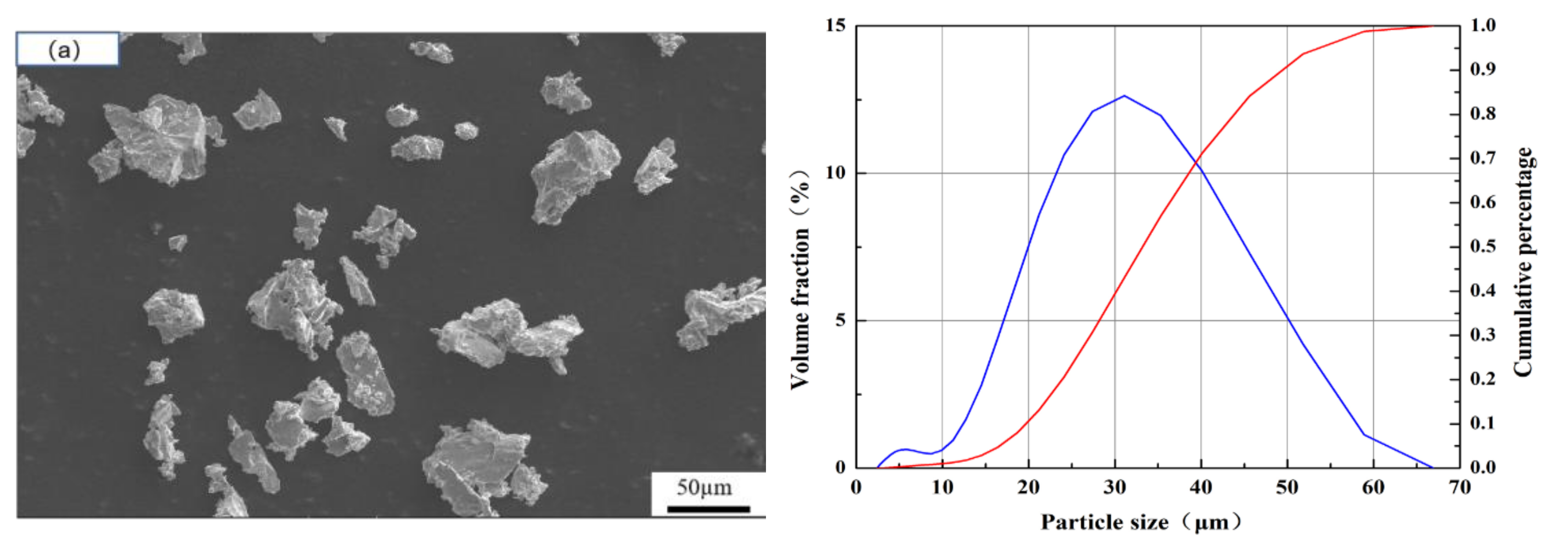
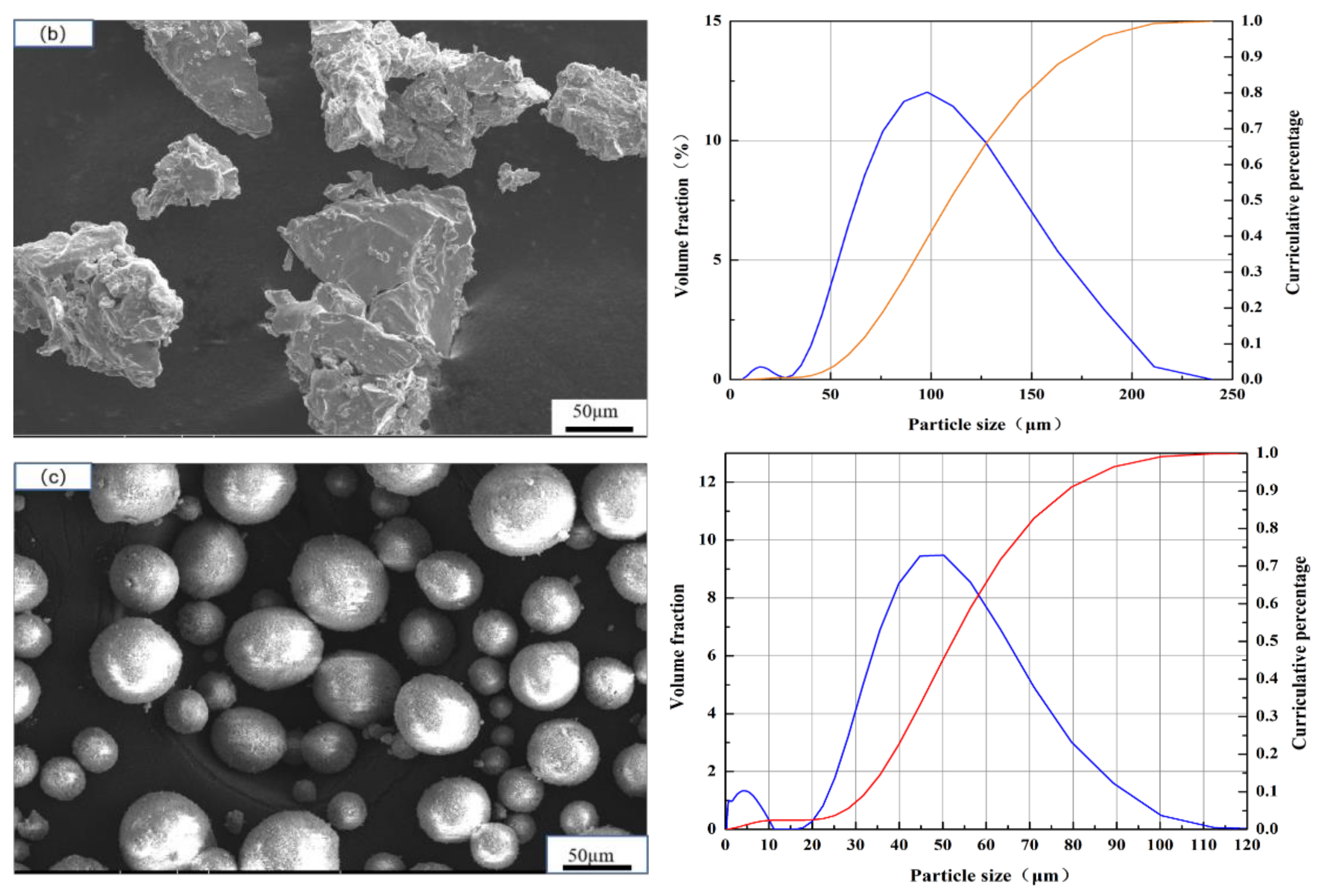
2.1. Coating Deposition

PEEK substrates (melting point 334 °C, Junchen Plastic Material Company, Dongguan, China) of 25 mm diameter and 10 mm thick were used. They were degreased in ethanol and then grit-blasted prior to spraying. The Ti and HA powders (99.95%, Nanjing EPp Nanomaterials Co., LTD, Nanjing, China) were used in this work. The morphology and size of the powders are shown in Figure 1. The average size of spongy titanium powder was 30μm (Figure 1a), which was used to fabricate the bottom titanium coating; the average size of spongy titanium was 98 μm (Figure 1b), which was used to prepare the porous and rough titanium coating; the average size of HA powder was 45 μm (Figure 1c), which was used to fabricate the surface layer. Coatings were carried out by VPS with a F4-VB plasma gun (Oerlikon Metco, Winterthur, Switzerland). Table 1 sums up the VPS operating parameters.

2.2. Coating Characterization and Property

The thickness and porosity of the coating were measured in accordance with ASTM F1854. The porosity of the coating was analyzed and calculated by ImageJ on the polished cross-section of the coating. The pore characteristics were analyzed by industrial computed tomography (Vtomex S micron CT, General Electric Company, Boston, MA, USA). The surface roughness of all coatings was measured using the Profilometer (Mitatoya Surftest SJ-301, Bruker, Karlsruhe, Germany) to evaluate surface morphology to obtain the Ra. A FESEM (Nova-Nano-430, Hillsboro, OR, USA) was employed to observe the microstructure of the coating (morphology of cross section and surface). Additionally, EDS analysis (Oxford Incax sight 6427, Hillsboro, OR, USA) was conducted with the same equipment to study the composition of the coating. An X-ray diffractometer (D8 Advance, BRUCKER AXS, Karlsruhe, Germany) equipped with a Co-Kα anti-cathode (λ = 0.179 nm) was used to determine the phase composition of the coating (scanning step: 0.02°, scanning speed 2°/min, scanning range 20° to 80°). The crystallinity of the HA coating was calculated by the peak area ratio method [20,21]. The calculation formula was as follows:
Crystallinity % = A P A P + A C
where Ac was the total integrated area of the amorphous phase peaks within the range of 2θ (25°~37°) in the XRD image. AP was the total integrated area of all HA peaks within the range of 2θ (25°~37°) in the XRD image.
Finally, the bond strength of the sprayed coatings was determined by standard adhesion strength tests in accordance with ASTM F1147-05. During the measurement, a tensile load was applied to the sample at a crosshead velocity of 25 mm/min. The average bond strength and standard deviation were measured for every six samples.

2.3. Influence of the Coating Process on the Thermal-Chemical PEEK Properties

The thermal–chemical properties (glass transition, melting temperature) were evaluated using dynamic difference calorimetry (STA-449-F5, Semb, Germany) in accordance with ASTM D3418-12, using samples with a diameter of 3 mm and height of 1.5 mm. Coated samples as well as uncoated samples were tested. The samples were heated from 40 to 400 °C with a heating rate of 10 °C/min. Additionally, the infrared absorption spectrums were determined for coated and uncoated PEEK samples using a FTIR system (Nicolet IS5, Thermo Fisher, Waltham, MA, USA) with an attenuated total reflection (ATR) unit to evaluate if the coating process led to changes of the chemical structure of functional groups of the PEEK samples. The results of the dynamic difference calorimetry and ATR FT-IR absorption spectroscopy were compared to the requirements given in ASTM F2026-14 for medical PEEK.

3. Results and Discussions

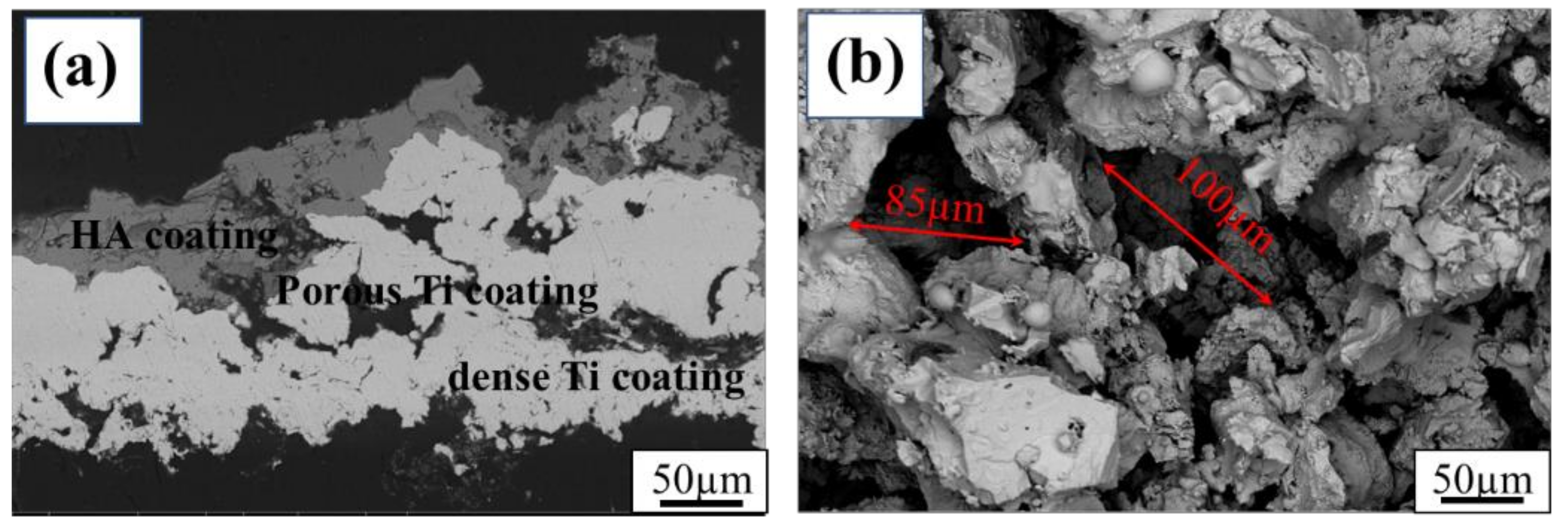
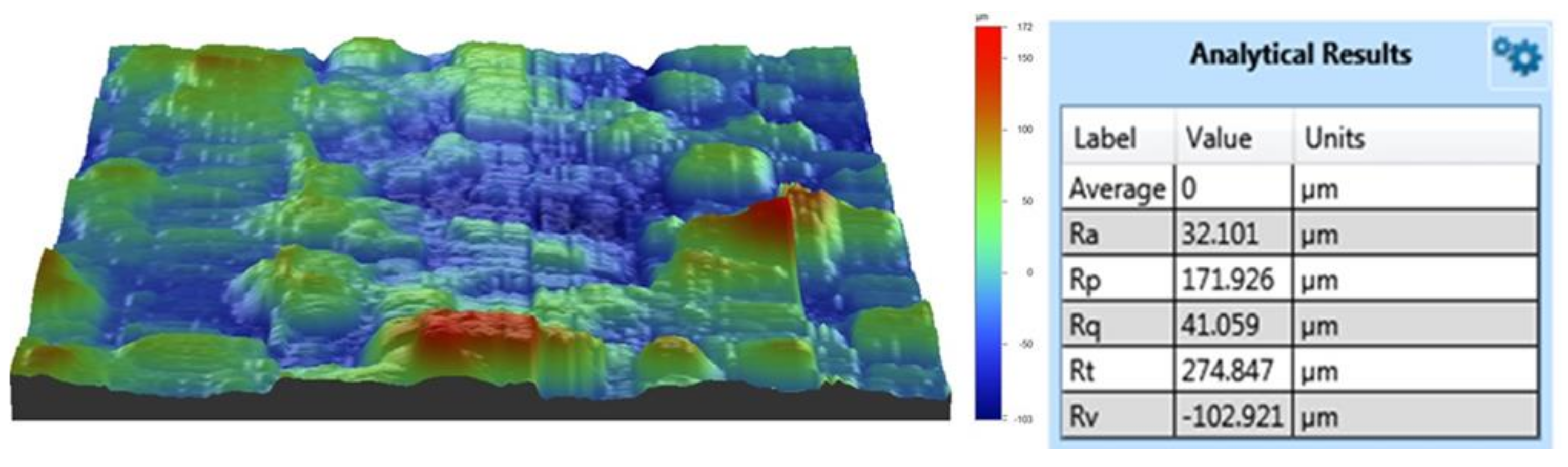
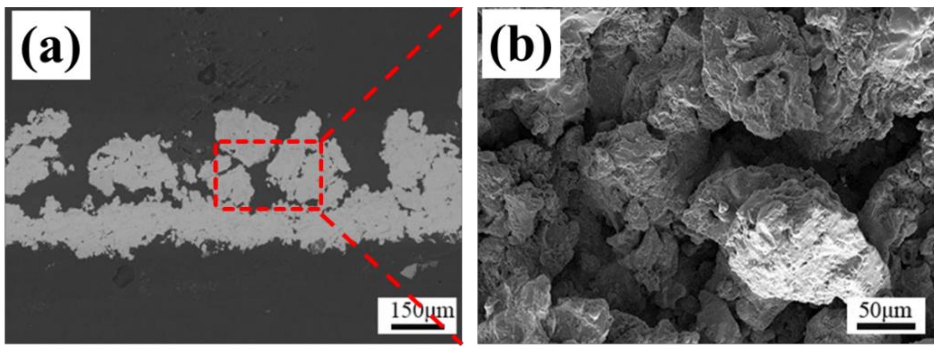
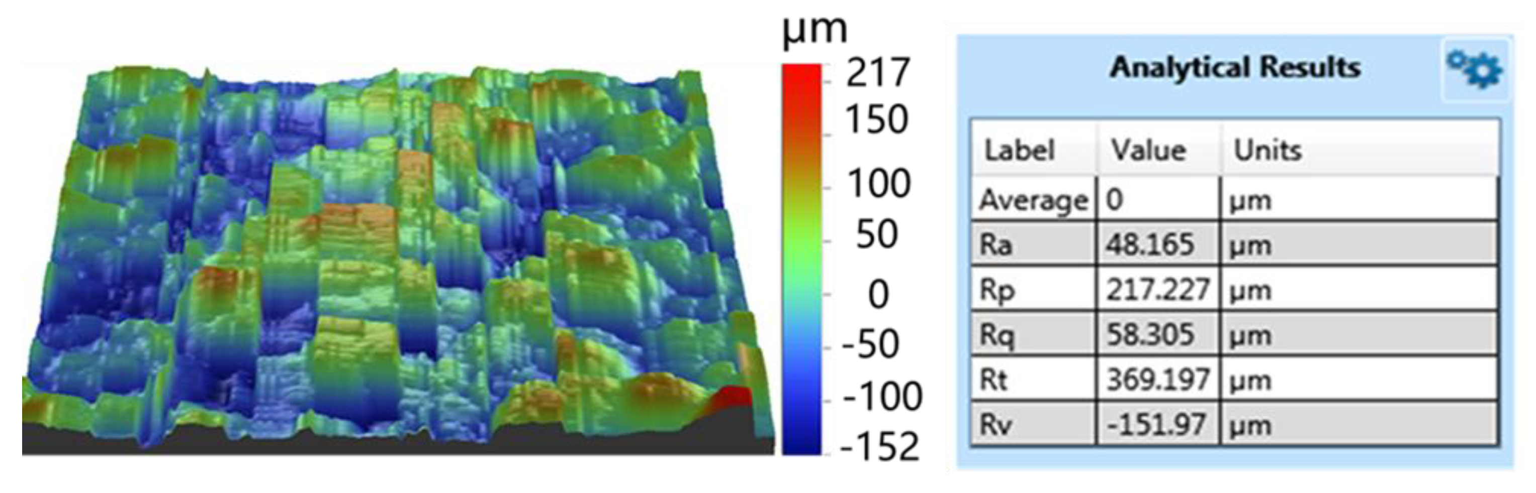
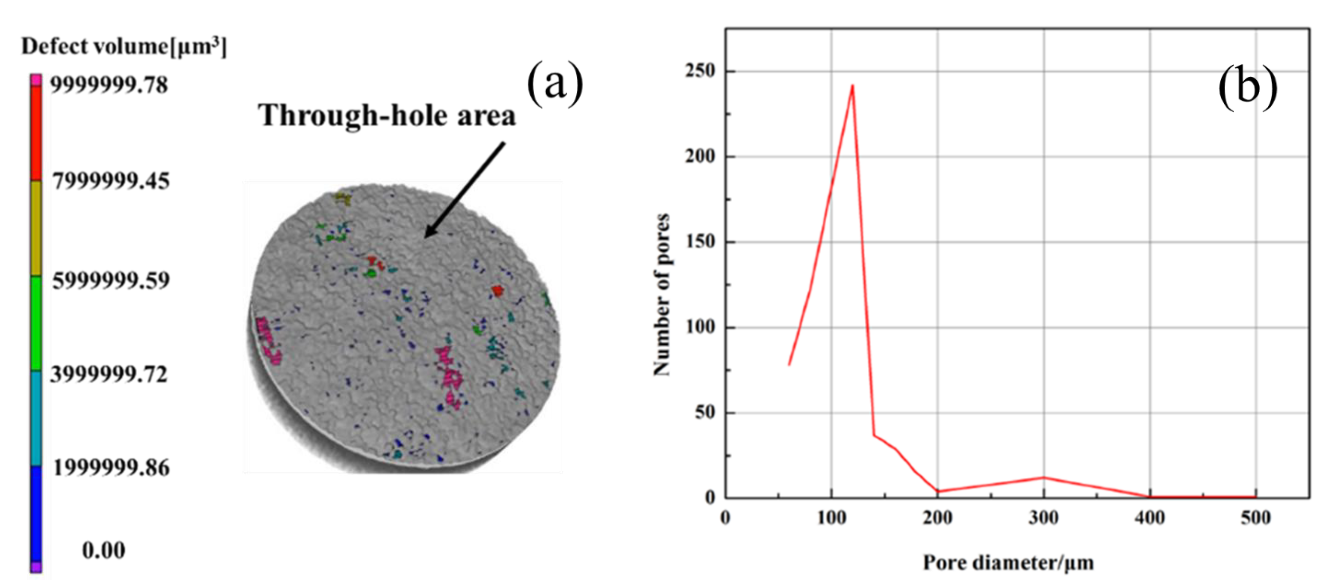
3.1. Coating Thickness, Porosity, and Roughness

The morphology of the Ti/Ti/HA coating is shown in Figure 2. The deposited coating presented an obvious three-layer structure. The bottom was a dense Ti coating with a porosity less than 10%; the middle was a porous Ti coating with the porosity of 35% ± 10% and a roughness of Ra = 34 ± 15 μm; the surface coating was a thin HA coating with a thickness of 30 ± 10 μm, a roughness of Ra = 30 ± 10 μm (Figure 3). The thickness, porosity and roughness of each layer were shown in Table 2. The total thickness of the composite Ti/Ti/HA coating was 200 ± 30 μm, which was within the thickness range (50–300 μm) reported in the relevant literature for PEEK implant coating applications [22]. Each layer had different thickness, porosity, and roughness for different purposes. The porosity and surface roughness of the coating mainly depended on the plasma spraying parameters and the sprayed powder characteristics. Compared with the middle titanium coating, the powder size of the bottom titanium coating was relatively smaller (d50 = 38 μm), and the plasma spraying power was greater. Therefore, the powder melting degree was high, and the deposited bottom coating was dense, thus improving the bonding strength of the coating (Figure 4 and Figure 5). The middle titanium coating presented a porous structure in the form of interconnected pores, with a porosity 35% ± 10% and a large pore size (partial pore sizes have been marked in Figure 2b). The pores in the coating will facilitate the transportation of liquid, the formation of capillaries, and promote the formation of new bone tissue [23,24]. The industrial computed tomography (CT) results showing the pore diameter distribution of the coating are presented in Figure 6. As it can be seen, the pore diameter of the coating was mainly between 80 and 120 μm, and the maximum pore size reached 300 μm. Due to vascularization, the pore size has been shown to influence the process of bone formation. Small pores favor hypoxic conditions that induce osteochondrogenic cells prior to osteogenesis, while large pores, which are well vascularized, lead to direct osteogenesis (without osteochondrogenic cells) [17]. In addition, a porous layer could provide an adequate conduit for bone ingrowth and avoided tissue necrosis common at the center of large fully porous implants in cases of limited vascular and nutrient supply [25].

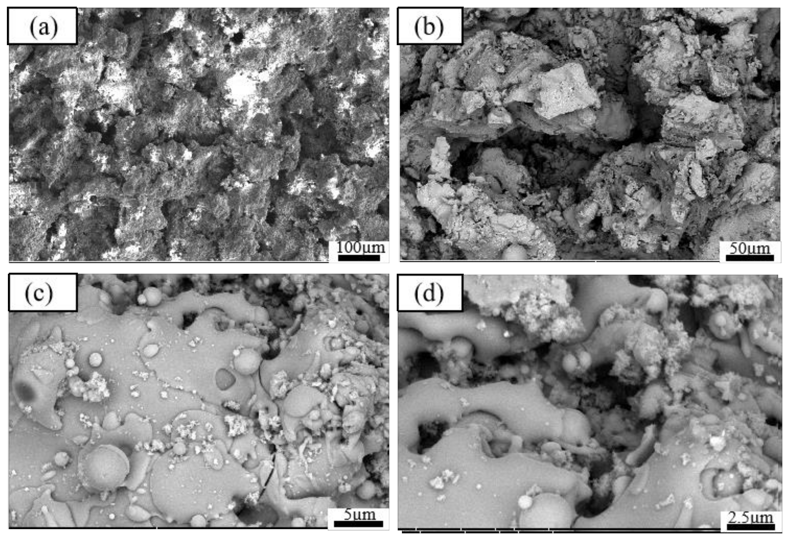
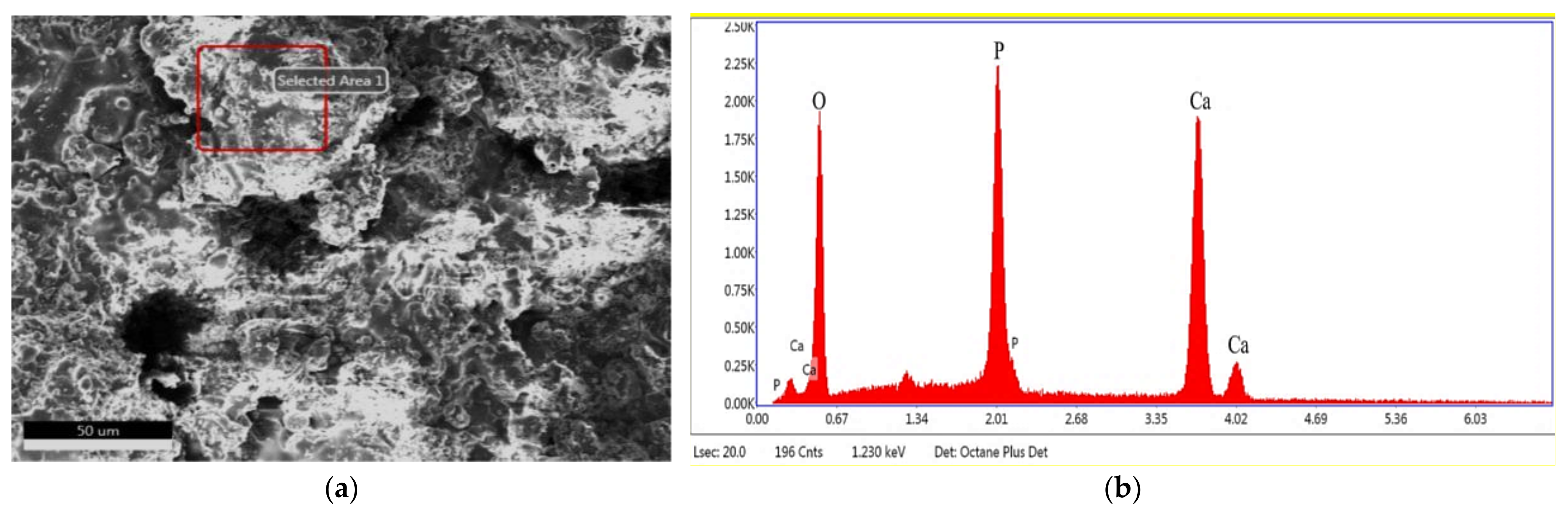
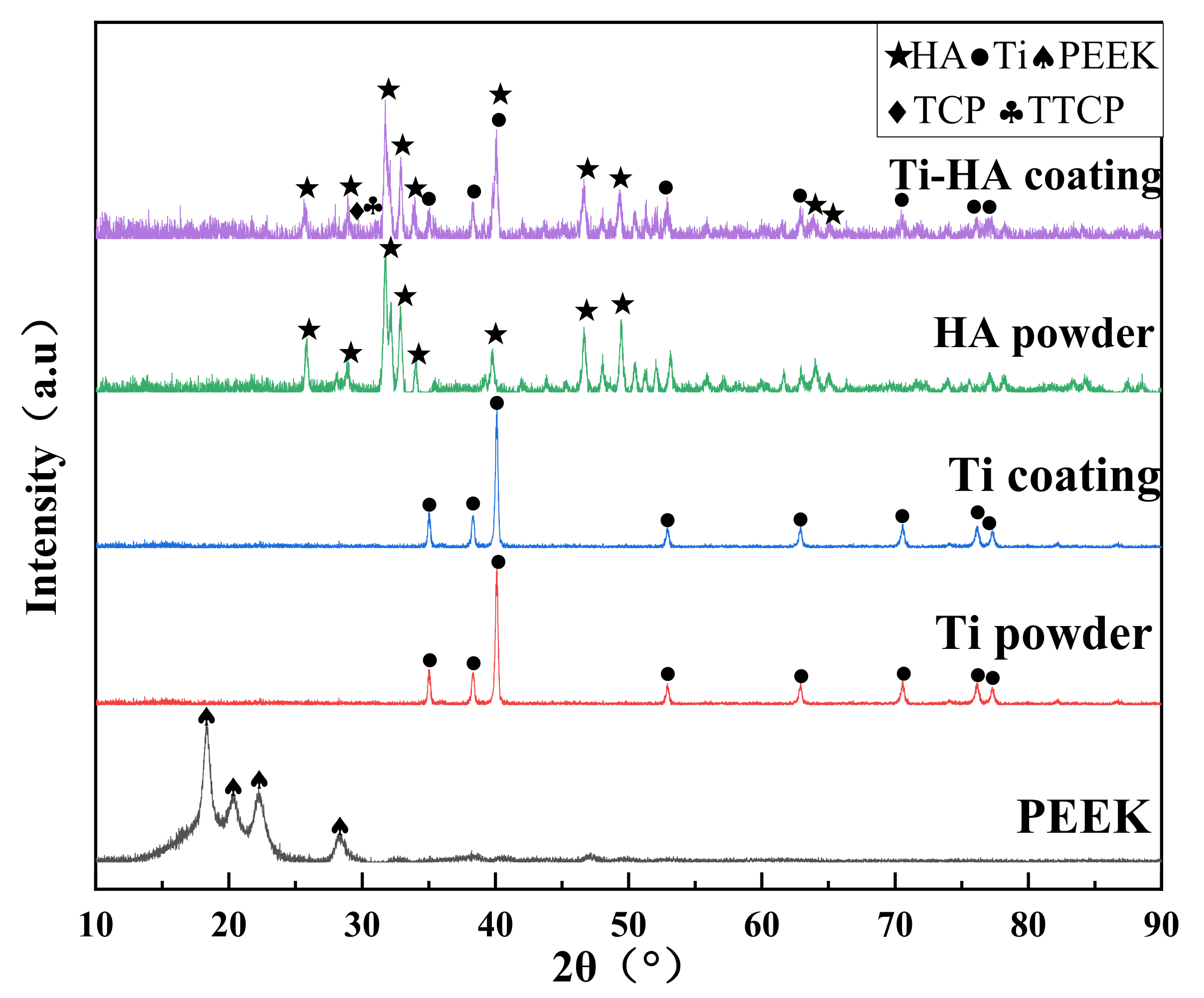
3.2. Coating Surface Morphology, Phase Composition and Crystallinity

The surface morphology of the PEEK-coating at different magnification was shown in Figure 7. The flat particles of the coating surface were connected to each other to form a continuous phase. The un-melted particles were embedded in the continuous phase to form a cavity-like structure or in the form of spherical droplets, which ended up with a rough coated surface. Besides, many irregular pores of different sizes and shapes were found in the coating. Overall, the coating ensures its integrity. The EDS analysis of the coating surface showed that the main HA elements (Ca, P, O) were contained on the coating surface (seen in Figure 8). Moreover, the Ca/P of the coating was 1.9, which was slightly higher than that of original HA powder (Ca/P: 1.7). The tetra calcium phosphate phase (TTCP) was the only calcium phosphate phase with Ca/P greater than that of HA. It indicated that the amorphous phases existed on the surface of the coating. The XRD spectrums of the original powders (Ti, HA) and the coatings are shown in Figure 9. The XRD results presented that the phase of the VPS-Ti coating is the pure Ti phase, which avoided the use of traditional APS-sprayed Ti coating to generate impure phases (TiO2, TiN, etc.), causing cracks in the coating [26]. In addition, the phase composition of the surface coating was mostly the HA phase, and the diffraction peaks of the HA coating were sharper than the original HA powder, indicating that the VPS-sprayed HA coating had higher crystallinity. At the same time, the Ti phase and the tricalcium phosphate phase (TCP) and TTCP phases with weaker diffraction intensity were also found in the spectrum of the HA coating, which confirmed the existence of the amorphous phase. The existence of the Ti phase diffraction peaks in the surface coating was the result of the diffraction of the middle Ti coating due to the thin and uneven thickness of the HA surface coating. There were a small amount of TCP and TTCP amorphous phases in the HA coating. During the plasma spraying process, some particles of the HA powder were more fully melted; the melted HA particle would be rapidly quenched as impacting onto the substrate, which caused the solidified HA particles to incompletely crystallize and form the amorphous phase. According to the reports, HA was extremely unstable and decomposes easily at high temperatures (above 1300 °C), and its chemical reaction equation was shown in the following formula [27]:
Ca10(PO4)6(OH)2 (HA)→2Ca3(PO4)2 (TCP) +Ca4(PO4)2O (TTCP) + H2O
Ca4(PO4)2O (TTCP)→Ca3(PO4)2 (TCP) + CaO
The crystallinity of HA affects the stability of the coating in human body fluids. Since the solubility of TCP, TCP, CaO and other amorphous phases in body fluids was much higher than that of HA, the too fast degradation rate could easily lead to early dissolution failure of the coating. On the other hand, the appropriate dissolution of Ca and P in the coating could help the growth of new bone tissue, allowing the implant to form a chemical and biological bond with the bone [28]. Hence, the lower spraying power (<45 KW) and hydrogen flow (<8 L/min) were used in the experiments to obtain a higher crystallinity of HA coating in this study. According to the calculation (1), the crystallinity of HA reached more than 90%. Moreover, the lower spraying power also helped to increase the roughness of the HA coating, thereby increasing the contact area between the porous surface of the implant and the bone tissue, and improving the stability of the implant.

3.3. Influence of the Coating Process on Thermal-Chemical PEEK Properties

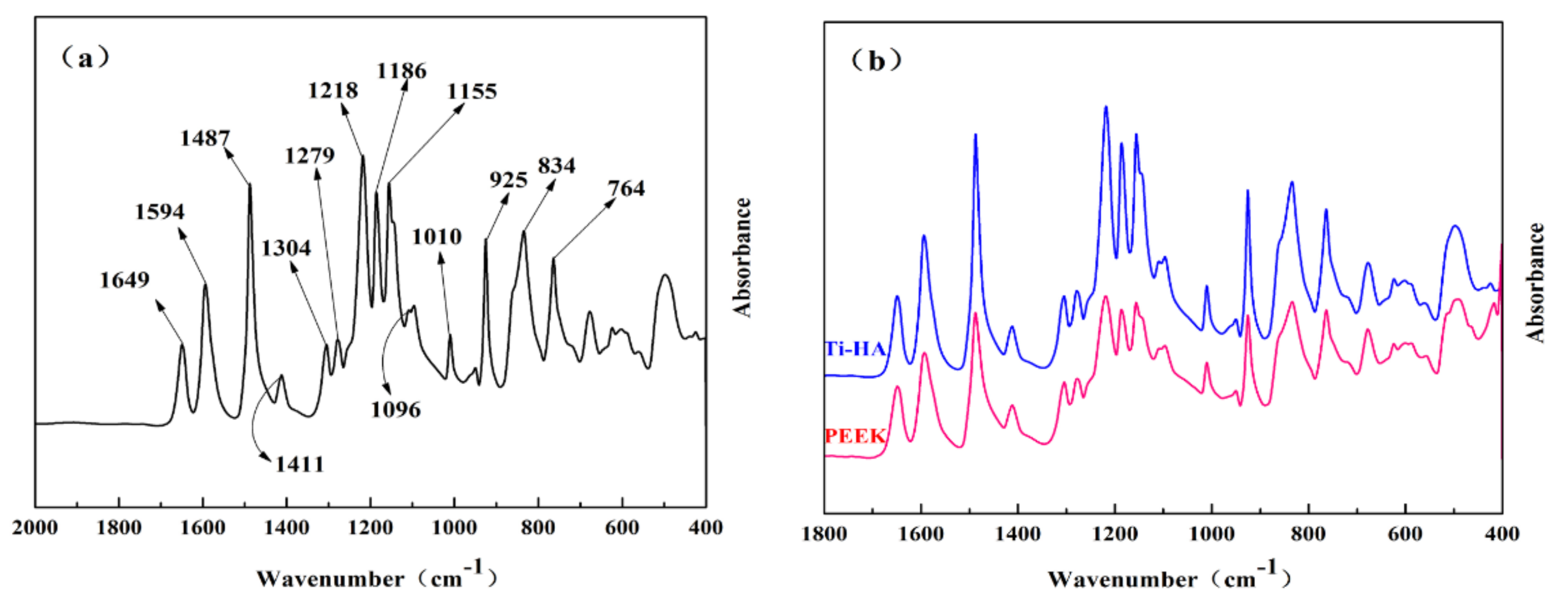
3.3.1. ATR FT-IR Spectroscopy

The infrared spectrum of the fingerprint region of coated PEEK are presented in the Figure 10a. The characteristic peaks of the PEEK polymer were clearly visible. The 1649 cm−1 represented the stretching vibration band (νC=O) of the carbonyl group (C=O); the 1594, 1487, 1411 cm−1 represented Ar–O–Ar (Ar is an aryl group, the same below) benzene ring plane vibration band (νΦ–O–Φ); the 1304 cm−1 represented the plane vibration band of Ar–CO–Ar benzene ring (νΦ–CO–Φ); the 1279, 1218, and 1186 cm−1 represented the asymmetric stretching vibration bands of Ar–O–Ar (νasΦ–O–Φ); the 1155 and 1010 cm−1 represented the C–H in-plane bending vibration bands (γC–H) of the benzene ring in the aryl ether or aryl ketone structure; the Ar–CO–Ar symmetric stretching vibration band (νsΦ–CO–Φ) was at 925 cm−1; and the 834 and 764 cm−1 was the out-of-plane bending vibration bands of the benzene ring C–H (ωC–H). These data were obtained from Fourier transform infrared spectroscopy, which were consistent with other relevant literature [29,30]. This indicated that the polymer material used in our study was semi-crystalline polyether ether ketone. The comparison of coated and uncoated PEEK in the infrared spectrum is presented in Figure 10b. The samples showed the characteristic peaks of PEEK, but the relative strength of some peaks was slightly different, which was caused by the uneven thickness of the sample. The samples still met the requirements of ASTM F2026. This indicated that the PEEK did not undergo any chemical changes during the spraying process.

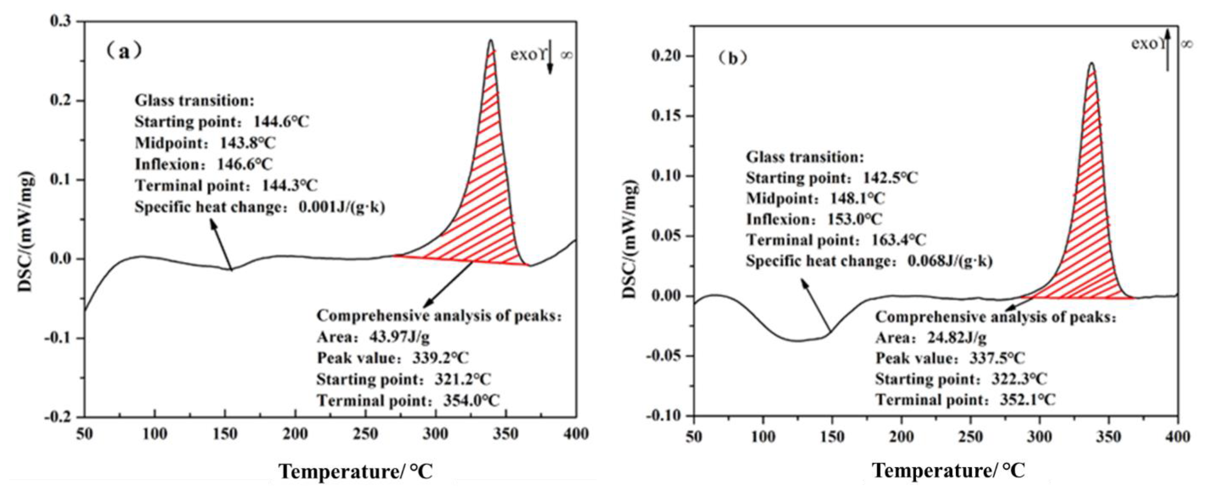
3.3.2. Dynamic Difference Scanning Calorimetry

The dynamic different scanning calorimetry (DSC) from 40 to 400 °C of the uncoated PEEK and coated PEEK were determined, respectively. The results are presented in the Figure 11. The glass transition temperature was around 140 °C and a melting endothermic peak was round 339 °C in Figure 11a,b. These test results are both within the range required by ASTM F2026 standards, as shown in Table 3. This indicated that the plasma spraying technology had no effect on PEEK thermal performance. PEEK has a melting point of 334 °C, while plasma spray particles can reach temperatures of several thousand °C. However, the PEEK matrix is cooled by compressed air during spraying, and the temperature of the PEEK matrix is always kept below 200 °C. Therefore, there is almost no influence on the thermal physical properties of PEEK matrix material, and the test results are within the standard range.

4. Interface Bonding Mechanism of Coatings

The macro fracture morphology of the coating after the bond strength tests are shown in Figure 12a. All samples were observed to be a mixture of adhesion failure and cohesion failure at the fracture interface [31]. It can be seen from the figure that the fracture surface is incomplete, and the area fraction of cohesive failure was far less than the adhesive fracture. Therefore, the bond strength was mainly reflected in the adhesion strength between the coating and the interface. The overall bond strength of the coating was related to the thickness of the coating, the bonding strength between layers, the porosity of the coating and the properties of the glue used [32]. For example, the excessive glue penetration into the coating would weaken the interlayer structure of the coating, thus strengthening the bond between the coating and the PEEK substrate, which had a great impact on the bond strength of the coating. Therefore, the thinner coatings tended to obtain higher bond strength. In this paper, the coating with a thickness of about 200 μm was prepared to reduce the effects of the thickness and the amount of glue on the bond strength in a certain range. The microscopic diagram of the fracture interface after the bond strength test is shown in Figure 12b. We could infer that there was a strong mechanical interlocking and diffusion connection at the interface of the coating and substrate. However, the middle Ti coating provided more fracture paths of the coating due to its porosity, which had a negative impact on the bond strength of the coating to some extent. On the other hand, its rough surface and curved profile increased the contact area between the layers, and the stronger interfacial bite force made up for the deficiency of the porosity in the bonding strength. As a result, the average bond strength of the Ti/Ti/HA reached 32 MPa, which was more than that of the FDA’s clinical requirement (>22 MPa). The bonding strength of the Ti/Ti/HA composite coating is shown in Table 4.

5. Conclusions

The Ti/Ti/HA composite coatings were deposited on the PEEK by VPS. The coatings presented an obvious three-layer structure: a dense bottom titanium coating with a porosity < 10%; a rough porous intermediate titanium coating with a porosity of 35% ± 10%, and a roughness of Ra = 34 ± 15 μm; and a top hydroxyapatite coating with a crystallinity greater than 90%. The average bonding strength of the coating reaches 32 MPa, which was greater than that of FDA (22 MPa). In addition, the TG-DSC and AIR-FTIR were performed on PEEK without coating and after coating. The results showed that the plasma spraying process had no effect on PEEK’s thermal–chemical performance.

Author Contributions

Conceptualization, F.H. and X.F.; methodology, J.S.; software, X.Y.; validation, M.L., D.Z. and C.D.; formal analysis, C.N.; investigation, M.L.; resources, F.P.; data curation, F.H.; writing—original draft preparation, F.H.; writing—review and editing, X.F.; visualization, F.P.; supervision, M.L.; project administration, X.F.; funding acquisition, C.D. All authors have read and agreed to the published version of the manuscript.

Funding

The authors are grateful for the financial support from the Science Technology Project of Guangdong Academy (2021GDASYL-20210103062), the Guangdong Key Laboratory of Modern Surface Engineering Technology (Grant No 2020B1212060049), the Guangdong Special Support Program (No. 2019 BT02C629), and the Guangzhou Major Projects of Industry-University-Research (IUR) Collaborative Innovation “Surface Treatment and Repair for Key Components of Industrial Gas Turbine (IGT)”.

Institutional Review Board Statement

Not applicable.

Informed Consent Statement

Not applicable.

Data Availability Statement

Not applicable.

Conflicts of Interest

The authors declare no conflict of interest.

References

  1. Ma, R.; Tang, T. Current strategies to improve the bioactivity of PEEK. Int. J. Mol. Sci. 2014, 15, 5426–5445. [Google Scholar] [CrossRef] [PubMed] [Green Version]
  2. Mavrogenis, A.F.; Vottis, C.; Triantafyllopoulos, G.; Papagelopoulos, P.J.; Pneumaticos, S.G. PEEK rod systems for the spine. Eur. J. Orthop. Surg. Traumatol. 2014, 24 (Suppl. S1), 111–116. [Google Scholar] [CrossRef] [PubMed]
  3. Zhao, Y.; Wong, H.M.; Wang, W.; Li, P.; Xu, Z.; Chong, E.Y.; Yan, C.H.; Yeung, K.W.; Chu, P.K. Cytocompatibility, osseointegration, and bioactivity of three-dimensional porous and nanostructured network on polyetheretherketone. Biomaterials 2013, 34, 9264–9277. [Google Scholar] [CrossRef]
  4. Rao, P.J.; Pelletier, M.H.; Walsh, W.R.; Mobbs, R.J. Spine interbody implants: Material selection and modification, functionalization and bioactivation of surfaces to improve osseointegration. Orthop. Surg. 2014, 6, 81–89. [Google Scholar] [CrossRef]
  5. Walsh, W.R.; Pelletier, M.H.; Bertollo, N.; Christou, C.; Tan, C. Does PEEK/HA enhance bone formation compared with PEEK in a sheep cervical fusion model. Clin. Orthop. Relat. Res. 2016, 474, 2364–2372. [Google Scholar] [CrossRef] [PubMed] [Green Version]
  6. Buck, E.; Li, H.; Cerruti, M. Surface Modification strategies to improve the osseointegration of poly(etheretherketone) and its composites. Macromol. Biosci. 2020, 20, 1900271. [Google Scholar] [CrossRef]
  7. Almasi, D.; Iqbal, N.; Sadeghi, M.; Sudin, I.; Abdul Kadir, M.R.; Kamarul, T. Preparation methods for improving PEEK’s bioactivity for orthopedic and dental application: A review. Int. J. Biomater. 2016, 2016, 1–12. [Google Scholar] [CrossRef] [Green Version]
  8. Robotti, M.P.; Zappini, M.G. Thermal plasma spray deposition of titanium and hydroxyapatite on PEEK implants. In PEEK Biomaterials Handbook, 2nd ed.; William Andrew: New York, NY, USA, 2019; pp. 147–177. [Google Scholar]
  9. Guner, A.T.; Meran, C. A review on plasma sprayed titanium and hydroxyapatite coatings on polyetheretherketone implants. Int. J. Surf. Sci. Eng. 2019, 13, 237. [Google Scholar] [CrossRef]
  10. Singh, J.; Chatha, S.S.; Sidhu, H.S. Synthesis and characterization of plasma sprayed functional gradient bioceramic coating for medical implant applications. Ceram. Int. 2020, 47, 9143–9155. [Google Scholar] [CrossRef]
  11. Ha, S.W.; Gisep, A.; Mayer, J.; Wintermantel, E.; Gruner, H.; Wieland, M. Topographical characterization and microstructural interface analysis of vacuum-plasma-sprayed titanium and hydroxyapatite coatings on carbon fiber-reinforced poly(etheretherketone). J. Mater. Sci. Mater. Med. 1997, 8, 891–896. [Google Scholar] [CrossRef]
  12. Jx, A.; Ha, B.; Sk, A.; Mo, C. Enhancement of mineralization on porous titanium surface by filling with nano-hydroxyapatite particles fabricated with a vacuum spray method—ScienceDirect. Mater. Sci. Eng. 2020, 111, 110772. [Google Scholar]
  13. Arifin, A.; Sulong, A.B.; Muhamad, N.; Syarif, J.; Ramli, M.I. Material processing of hydroxyapatite and titanium alloy (HA/Ti) composite as implant materials using powder metallurgy: A review. Mater. Des. 2014, 55, 165–175. [Google Scholar] [CrossRef]
  14. Singh, A.; Singh, G.; Chawla, V. Mechanical properties of vacuum plasma sprayed reinforced hydroxyapatite coatings on Ti-6Al-4V alloy. J. Aust. Ceram. Soc. 2017, 53, 795–810. [Google Scholar] [CrossRef]
  15. Suska, F.; Omar, O.; Emanuelsson, L.; Taylor, M.; Gruner, P.; Kinbrum, A.; Hunt, D.; Hunt, T.; Taylor, A.; Palmquist, A. Enhancement of CRF-PEEK osseointegration by plasma-sprayed hydroxyapatite: A rabbit model. J. Biomater. Appl. 2014, 29, 234. [Google Scholar] [CrossRef] [PubMed]
  16. Gkomoza, P.; Lampropoulos, G.; Vardavoulias, M.; Pantelis, D.; Karakizis, P.; Sarafoglou, C. Microstructural investigation of porous titanium coatings, produced by thermal spraying techniques, using plasma atomization and hydride-dihydride powders, for orthopedic implants. Surf. Coat. Technol. 2019, 357, 947–956. [Google Scholar] [CrossRef]
  17. Karageorgiou, V.; Kaplan, D. Porosity of 3D biomaterial scaffolds and osteogenesis. Biomaterials 2005, 26, 5474–5491. [Google Scholar] [CrossRef]
  18. De Vasconcellos, L.M.R.; Carvalho, Y.R.; do Prado, R.F.; de Vasconcellos, L.G.O.; de Alencastro Graça, M.L.; Cairo, C.A.A. Porous titanium by powder metallurgy for biomedical application: Characterization, cell cytotoxicity and in vivo tests of osseointegration. Biomed. Eng. Tech. Appl. Med. 2012, 47–74. [Google Scholar] [CrossRef] [Green Version]
  19. Ryan, G.; Pandit, A.; Apatsidis, D.P. Fabrication methods of porous metals for use in orthopedic applications. Biomaterials 2006, 27, 2651–2670. [Google Scholar] [CrossRef]
  20. Wang, B.C.; Chang, E.; Lee, T.M. Changes in phases and crystallinity of plasma-sprayed hydroxyapatite coatings under heat treatment: A quantitative study. J. Biomed. Mater. Res. 1995, 29, 1483–1492. [Google Scholar] [CrossRef]
  21. Mcpherson, R.; Gane, N.; Bastow, T.J. Structural characterization of plasma-sprayed hydroxyapatite coatings. J. Mater. Sci. Mater. Med. 1995, 6, 327–334. [Google Scholar] [CrossRef]
  22. Sargin, F.; Erdogan, G.; Kanbur, K.; Turk, A. Investigation of in vitro behavior of plasma sprayed Ti, TiO2 and HA coatings on PEEK. Surf. Coat. Technol. 2021, 411, 126965. [Google Scholar] [CrossRef]
  23. Takemoto, M.; Fujibayashi, S.; Neo, M.; Suzuki, J.; Kokubo, T.; Nakamura, T. Mechanical properties and osteoconductive of porous bioactive titanium. Biomaterials 2005, 26, 6014–6023. [Google Scholar] [CrossRef] [PubMed]
  24. Otsuki, B.; Takemoto, M.; Fujibayashi, S.; Neo, M.; Kokubo, T.; Nakamura, T. Pore throat size and connectivity determine bone and tissue ingrowth into porous implants: Three-dimensional micro-CT based structural analyses of porous bioactive titanium implants. Biomaterials 2006, 27, 5892–5900. [Google Scholar] [CrossRef] [Green Version]
  25. Evans, N.T.; Torstrick, F.B.; Lee, C.S.; Dupont, K.M.; Safranski, D.L.; Chang, W.A.; Macedo, A.E.; Lin, A.S.; Boothby, J.M.; Whittingslow, D.C.; et al. High-strength, surface-porous polyether-ether-ketone for load-bearing orthopedic implants. Acta Biomater. 2015, 13, 159–167. [Google Scholar] [CrossRef] [PubMed] [Green Version]
  26. Zheng, X.B.; Ji, H.; Huang, J.Q.; Ding, C.X. Plasma sprayed Ti and HA coatings: A comparative study between APS and VPS. Acta Metall. Sin. (Engl. Lett.) 2005, 18, 339–344. [Google Scholar]
  27. Lazić, S.; Zec, S.; Miljević, N.; Milonjić, S. The effect of temperature on the properties of hydroxyapatite precipitated from calcium hydroxide and phosphoric acid—ScienceDirect. Thermochim. Acta 2001, 374, 13–22. [Google Scholar] [CrossRef]
  28. Xiao, G.Y.; Lu, Y.P.; Xu, W.H.; Zhu, R.F. Microstructure and cytocompatibility of plasma sprayed gradient hydroxyapatite coatings. Surf. Eng. 2015, 31, 860–866. [Google Scholar] [CrossRef]
  29. Vogel, D.; Dempwolf, H.; Baumann, A.; Bader, R. Characterization of thick titanium plasma spray coatings on PEEK materials used for medical implants and the influence on the mechanical properties. J. Mech. Behav. Biomed. Mater. 2017, 77, 600–608. [Google Scholar] [CrossRef]
  30. Reitman, M.; Jaekel, D.J.; Siskey, R.; Kurtz, S.M. Chapter 4–morphology and crystalline architecture of polyaryletherketones. In PEEK Biomaterials Handbook, 2nd ed.; William Andrew: New York, NY, USA, 2019; pp. 53–66. [Google Scholar]
  31. Singh, A.; Singh, G.; Chawla, V. Characterization and mechanical behavior of reinforced hydroxyapatite coatings deposited by vacuum plasma spray on SS-316L alloy. J. Mech. Behav. Biomed. Mater. 2018, 79, 273–282. [Google Scholar] [CrossRef] [PubMed]
  32. Surmenev, R.A. A review of plasma-assisted methods for calcium phosphate-based coatings fabrication. Surf. Coat. Technol. 2012, 206, 2035–2056. [Google Scholar] [CrossRef]
Figure 1. Size and morphology of the feedstocks: (a) spongy titanium powder with fine size; (b) spongy titanium powder with coarse size; (c) spherical hydroxyapatite powder.
Coatings 12 00433 g001aCoatings 12 00433 g001b
Figure 2. SEM micrographs of the Ti/Ti/HA coating: (a) cross section, (b) porous structure.
Coatings 12 00433 g002
Figure 3. Roughness of the Ti/Ti/HA coating.
Coatings 12 00433 g003
Figure 4. Morphology of the Ti/Ti coating: (a) cross section, (b) porous structure.
Coatings 12 00433 g004
Figure 5. Roughness of the Ti coating.
Coatings 12 00433 g005
Figure 6. Industrial computed tomography of coating: (a) the pore distribution of the coating, (b) the statistics of pore diameter of coating.
Coatings 12 00433 g006
Figure 7. SEM images at different magnifications of the surface of Ti/Ti/HA coating: (a) ×200, (b) ×500, (c) ×5000, (d) ×10,000.
Coatings 12 00433 g007
Figure 8. Element distribution of the HA coating surface: (a) EDS scanning region, (b) corresponding element distribution.
Coatings 12 00433 g008
Figure 9. XRD spectrums of the original powder and coatings.
Coatings 12 00433 g009
Figure 10. ATR FT-IR spectroscopy graphs of PEEK: (a) the infrared spectrum of the fingerprint region of coated PEEK; (b) the comparison of coated and uncoated PEEK in the infrared spectrum.
Coatings 12 00433 g010
Figure 11. Dynamic difference calorimetry graphs of PEEK: (a) uncoated PEEK; (b) coated PEEK.
Coatings 12 00433 g011
Figure 12. The fracture morphology of the coating after the bonding strength tests: (a) the macro fracture morphology; (b) the microscopic diagram of the fracture interface.
Coatings 12 00433 g012
Table 1. Plasma spraying coating parameters.
Spraying ParametersTi
(Bottom Coating)
Ti
(Middle Coating)
HA
(Surface Coating)
Spraying distance (mm)260280320
Plasma gas (Ar/H2)40/540/440/6
Carried gas Ar (L·min−1)2.12.12.1
Robotic arm speed (mm/s)100010001000
Table 2. Thickness, porosity, and surface roughness of the coating.
Coating PropertiesBottom CoatingMiddle CoatingHA Coating
Thickness70 ± 10 μm100 ± 10 μm30 ± 10 μm
Porosity<10%35% ± 10%32% ± 10%
Roughness24 ± 5 μm34 ± 15 μm30 ± 10 μm
Table 3. Results of the dynamic difference calorimetry compared to the requirements of ASTM F2026.
PropertyASTM F2026 RequirementPEEK
(Uncoated)
PEEK
(Coated)
Glass transition temperature (°C)125–165145143
Melting temperature (°C)320–360339338
Table 4. Bond strength of the Ti/Ti/HA coating.
Number123456
Bond strength (MPa)303532313135
Publisher’s Note: MDPI stays neutral with regard to jurisdictional claims in published maps and institutional affiliations.

